Article

Nozzle Condition Monitoring System Using Root Mean Square of Acoustic Emissions during Abrasive Waterjet Machining

1
Department of Control and Instrumentation Engineering, Pukyong National University, Busan 48513, Korea
2
Precision Mechanical Process and Control R&D Group, Korea Institute of Industrial Technology, Busan 46938, Korea
*
Authors to whom correspondence should be addressed.
J. Manuf. Mater. Process. 2022, 6(2), 31; https://doi.org/10.3390/jmmp6020031
Submission received: 8 February 2022 / Revised: 28 February 2022 / Accepted: 1 March 2022 / Published: 7 March 2022
(This article belongs to the Topic Modern Technologies and Manufacturing Systems)

Abstract

:
Machining of difficult-to-cut materials such as titanium alloys, stainless steel, Inconel, ceramic, glass, and carbon fiber-reinforced plastics used in the aerospace, automobile, and medical industries is being actively researched. One non-traditional machining method involves the use of an abrasive waterjet, in which ultra-high-pressure water and abrasive particles are mixed and then ejected through a nozzle, and the thin jet stream cuts materials. The nozzle greatly affects the machining quality, as does the cutting tool of general machining, so it is very important to monitor the nozzle condition. If the nozzle is damaged or worn, or if the bore size increases or the bore becomes clogged with abrasive, the material may not be cut, or the surface quality of the cut may deteriorate. Here, we develop a nozzle monitoring system employing an acoustic emission sensor that detects the nozzle condition in real time.

1. Introduction

Waterjet machining is a cutting method in which a high-pressure water/abrasive mixture is delivered to the material surface via a nozzle. Pure waterjets are used to cut soft materials such as foods, medicines, fabrics, or wood. Such waterjets cannot cut metals or hard composites, so an abrasive waterjet (AWJ) is required [1,2,3,4,5,6,7,8,9,10,11,12,13,14,15,16,17,18]. Water at 300–600 MPa and abrasive particles (#50–200 mesh) are mixed, ejected at high speed via a nozzle (bore size 0.24–0.40 mm), and the material is cut by the jet stream. AWJ machining affords excellent surface quality and precision when fabricating complex shapes. Such machining can be integrated with industrial robotics and has benefited from advances in ultra-high-pressure pumps and nozzles. AWJs are increasingly being used to handle difficult-to-cut materials. AWJ machining does not require the (expensive) tools of conventional machines [19,20,21]. AWJ machining quality (surface roughness and cut depth, width, and shape) is affected by various factors [22]. The nozzle is very important: wear, damage, and bore expansion may cause abrasive clogging that reduces the quality of the cut surface. Nozzle condition must be monitored in real time and damaged nozzles must be replaced in a timely manner. Currently, nozzles are replaced entirely after 50–100 h of operation, based on the subjective judgment of operators [22].
In general, the lifetime of an AWJ nozzle is affected by processing parameters, nozzle properties, and any misalignment between the orifice and nozzle in the mixing head. Nozzle wear (which is directly related to nozzle lifetime) affects the waterjet pressure, orifice diameter, shapes and sizes of the abrasive particles, the abrasive feed rate, the bore diameter, and the angle/depth of the inlet cone [22]. Impacting abrasive particles carried by the waterjet create a wavy erosion zone, and the erosion propagates to the exit of the nozzle bore. The high-pressure water passes through the orifice of the mixing head to form a high-speed flow, and the abrasive particles are sucked into the chamber by the Venturi effect. The sucked-in abrasive particles do not mix with water on entry (because of the speed difference between particles and water). The particles thus collide with the nozzle wall while rotating along the periphery of the jet. When the abrasive particles become accelerated within the bore to a speed similar to that of the water, an abrasive jet becomes centered and is sprayed through the nozzle. Thus, until the particle speed equals that of the water, a wave pattern is generated in the nozzle, attributable to swirling flow [23].
Correct alignment of the orifice and nozzle of the mixing head is critical. If misalignment is in play, the abrasive particles do not pass directly through the nozzle and may collide with the nozzle wall. This changes the direction of particle flow, triggering eccentricity. Non-uniform nozzle wall collisions caused by swirling particle flow and misalignment disperse the jet energy, increase the jet plume diameter, and reduce the jet cutting force, in turn increasing surface roughness and reducing form accuracy.
Monitoring of the AWJ nozzle condition may be direct or indirect. Direct methods measure the nozzle diameter at regular intervals, while indirect methods assess nozzle density, hardness, or fracture toughness after processing. None of these methods accurately determine nozzle wear during processing. If the waterjet pressure changes temporarily, the abrasive grain shapes and distribution become non-uniform. This affects the alignment of the orifice and nozzle. A nozzle may thus not only wear out, but may suffer unpredictable damage. Researchers are investigating methods to directly measure nozzle wear; for example, one method involves using a gauge to measure the nozzle diameter (outlet bore) at regular intervals, and another evaluates the nozzle lifespan based on the weight loss rate [23]. Kovacevic developed a sensor that directly detects nozzle wear during AWJ machining [24], and Kovacevic and Zhang described an online monitoring system using the AWJ acoustic signal and nozzle wear estimation employing an autoregressive moving average (ARMA) spectrum [25]. Putza monitored nozzle wear and abrasive grain clogging by measuring the temperature of the waterjet head, nozzle sounds and vibration, and changes in flow rate, and various sensors were used to assess temperature, sounds, jet acceleration, and flow [26]. Prabu obtained acoustic signals at various abrasive feed rates and pressures and associated these with the extent of nozzle wear as the AWJ parameters varied [27]. However, few methods have been applied in the field.
Here, we develop a real-time nozzle condition monitoring system using the root mean square (RMS) values of an acoustic emission (AE) sensor. We collect AE signals by nozzle usage time at different waterjet pressures and abrasive feed rates, and convert these to AE RMS values in real time. If the AE RMS value does not lie within preset limits, or deviates from the desired average, this immediately indicates nozzle wear or damage.

2. Proposed System for Monitoring the Wear Condition of the Focusing Nozzle

Figure 1 presents a schematic of the nozzle condition monitoring system. An AE sensor monitors acoustic signals generated when the nozzle wall is eroded by abrasive particles. The sensor is installed under the coupling between the mixing head and the nozzle (which would be expected to generate the largest signal). Abrasive particles sprayed from the nozzle become partially scattered after colliding with the material and could impact the AE sensor, so the sensor is sheathed in urethane foam. A 5 mm-diameter stainless hemispherical ball and 1 mm-thick alumina (Al2O3) disc are attached to the front of the AE sensor (the portion in contact with the nozzle) to minimize attenuation of the acoustic signal while protecting the sensor. One part of the hemispherical ball is attached to the outer wall of the cylindrical nozzle by point contact, and the other part is attached to the AE sensor by surface contact through the alumina disc. The AE raw signal was transmitted to the AE sensor through the hemispherical ball and the alumina disc.
AE signal frequencies range from several tens of kHz to several MHz depending on the material properties [27], so the sampling frequency was set to 1 MHz when employing a nozzle fabricated from cemented carbide. A high-pass filter (HPF) with a cutoff of 50 kHz was used to remove power instability, external nozzle shocks, and low-frequency noise caused by ambient vibration.
Processing of AE raw signals acquired in real time may be slow because this generally involves large amounts of data and limited memory capacity. Therefore, we converted the AE signals to AE root mean square (RMS) values [3,27]. Since these are proportional to the amount of material removed when the impact energy of abrasive particles is continuously applied to the nozzle, it is possible to detect not only acoustic signals generated by tube expansion caused by uniform wear, but also signals generated when the material is removed via abnormal eccentricity and damage. Wear caused by uniform material removal gradually reduces the AE RMS values over time, and eccentricity and damage trigger abrupt signal fluctuations. AE RMS values optimally monitor real-time nozzle status in the workshop.

3. Experimental Setup of Our Proposed System

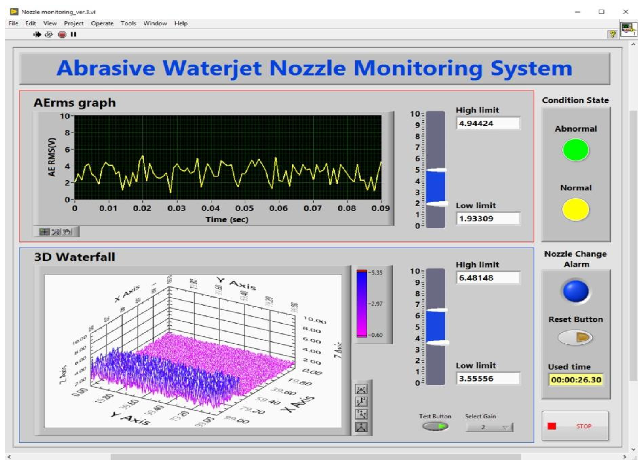
Figure 2 presents the system. The gantry was obtained from TOPS (Korea) and the AE sensor module is a Nano30 (150–750 kHz, PAC). When the waterjet head was directed at the workpiece, the AE raw signal was filtered using a pre-amplifier with built-in voltage amplifiers (gains of ×10, ×100, ×1000) and a high-pass filter (50 kHz) installed in the sensor. The AE raw signal was sampled at 1 MHz using an NI 6363 data acquisition board of NI PXIe-1082 chassis (ADC resolution of 16 bits and sampling rate of 2 MS/s (Mega Samples Per Second)), and converted into RMS values (units of 50 ms) employing an RMS-DC converter (AE-5A, PAC). Finally, the RMS values were acquired at 1 kHz using an NI USB-6259 A/D converter (ADC resolution of 16 bits and sampling rate of 1.25 MS/s) and transmitted to the monitoring program running on a PC. Figure 3 illustrates the monitoring of nozzle status using changes in the RMS signal. The program was created using LabVIEW (National Instruments) and features a signal-processing algorithm that converts analog to digital signals and extracts nozzle abnormalities.

4. Experimental Evaluation of Our Proposed System

We varied the time of nozzle use and monitored nozzle status using the AE signals, and also changed the waterjet pressure and abrasive feed rate. Table 1 lists the experimental conditions. Nozzle status was classified as normal, worn, or damaged: wear was defined as expansion of the nozzle bore diameter and damage was defined as eccentricity of the nozzle exit. We measured the nozzle outlet diameter and diameter changes in the longitudinal bore cross-section.
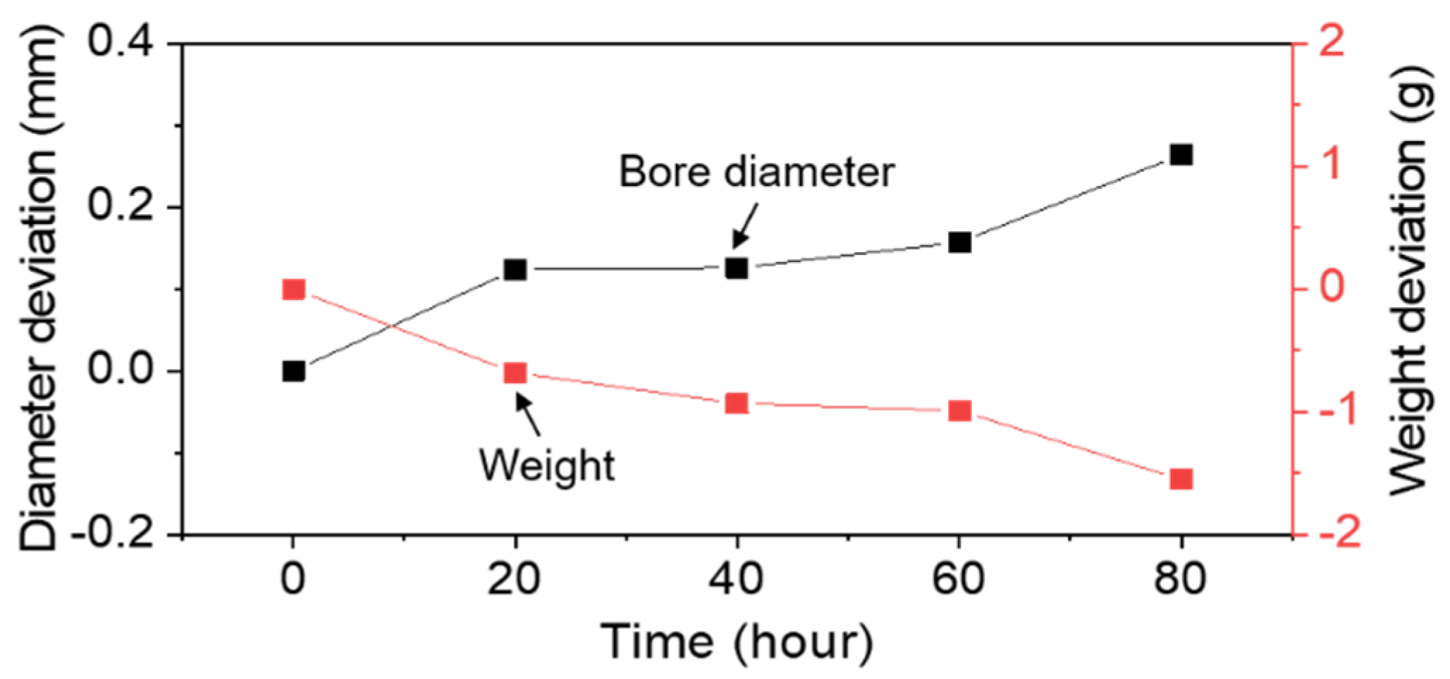
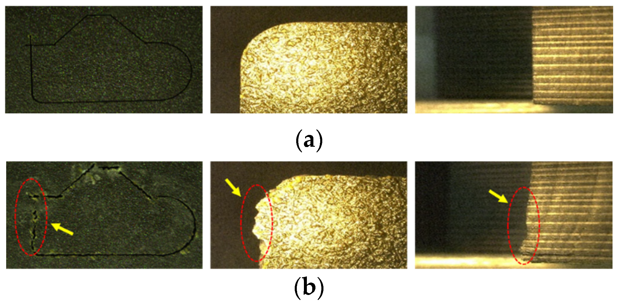
Figure 4 presents the bore diameter and cross-sectional status by nozzle usage time at a waterjet pressure of 350 MPa and an abrasive feed rate of 450 g/min. Figure 4a presents photographs of the bore of the nozzle outlet at 0, 40, and 80 h—damage is evident. The diameters were 0.984, 1.144, and 1.271 mm after 0, 40, and 80 h, and changes from 0 to 40 h and from 40 to 80 h were 0.16 and 0.127 mm, respectively. Figure 4b presents cross-sectional photographs of normal, worn, and damaged nozzles. The longitudinal bore diameter of a new nozzle is near uniform, but the diameter of a worn nozzle is wavy and that of a damaged nozzle is eccentric. Such abnormalities compromise the processing quality. Figure 5 presents the (symmetrical) changes in nozzle bore diameter and weight. The nozzle bore diameter continues to increase after 60 h and nozzle abrasion develops near 100 h. Figure 6 shows cross-sectional photographs of carbon fiber-reinforced plastic (CFRP) parts, when normal and damaged nozzles were used for waterjet processing. We verified that damaged nozzles deteriorate the quality of machining, such as form accuracy and surface roughness. This is because, depending on the state of the nozzle, the waterjet mixture goes straight or scatters from the tip of the nozzle.
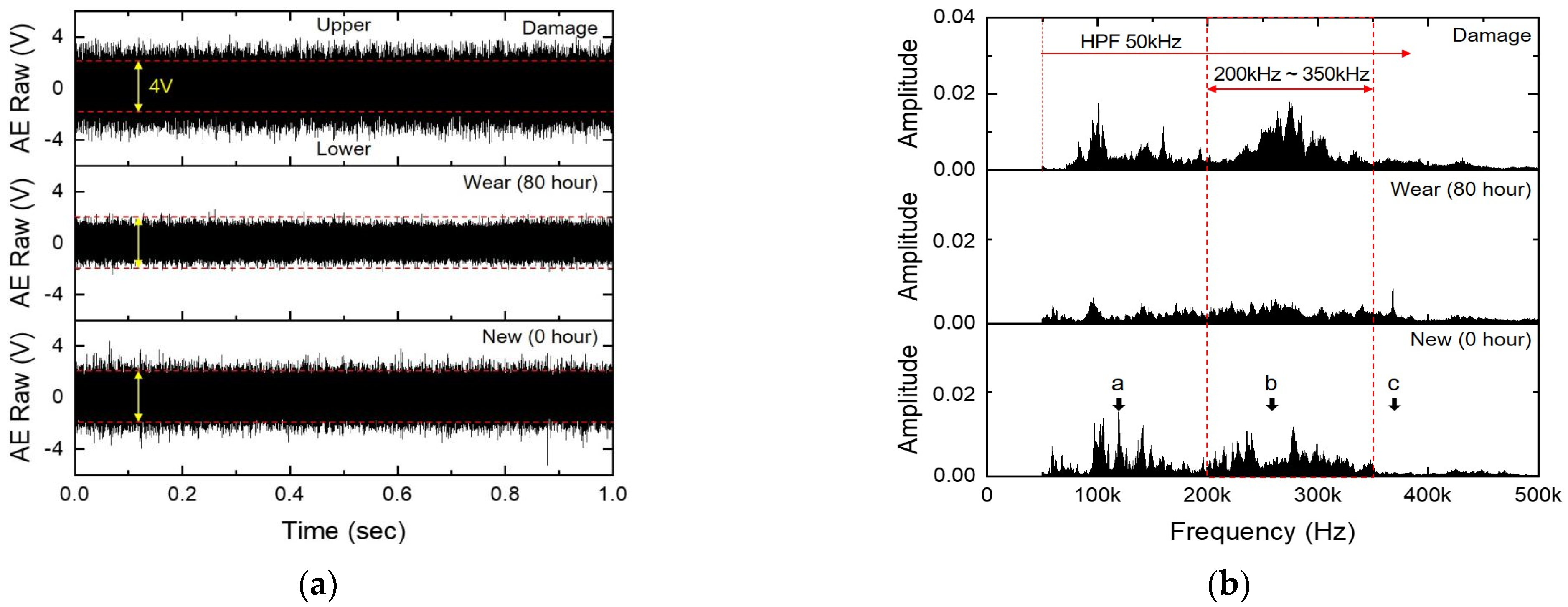
Figure 7 presents the original (0 h) AE signal and the fast Fourier transform (FFT). Here, the original AE signal was acquired for 1 s at a sampling rate of 1 MHz, and was analyzed by FFTW library of Origin2019b, which implements the Cooley-Turkey FFT algorithm and Rectangular Window. As shown in Figure 7a, the amplitude of the AE raw signal of a normal nozzle was ±2 V. After 80 h, nozzle wear caused AE amplitude to fall. In contrast, the AE raw signal amplitude of a damaged nozzle greatly increased. Figure 7b presents the FFT of the AE raw signal. The worn nozzle was associated with low amplitudes over the entire frequency range. In contrast, the damaged nozzle evidenced a very high amplitude between 240 and 280 kHz. When nozzle wear occurs, even when the waterjet pressure and the abrasive feed rate of a normal and worn nozzle are the same, the bore diameter of the worn nozzle widens, and the speed of the abrasive particles thus decreases. As particle kinetic energy is reduced, the nozzle wall collision energy falls, and thus so does the AE energy and the amplitude of the AE raw signal. However, if the nozzle wall is damaged by chipping or misalignment within the nozzle, many abrasive particles collide near the damaged area, increasing the AE energy and the amplitude of the raw AE signal.
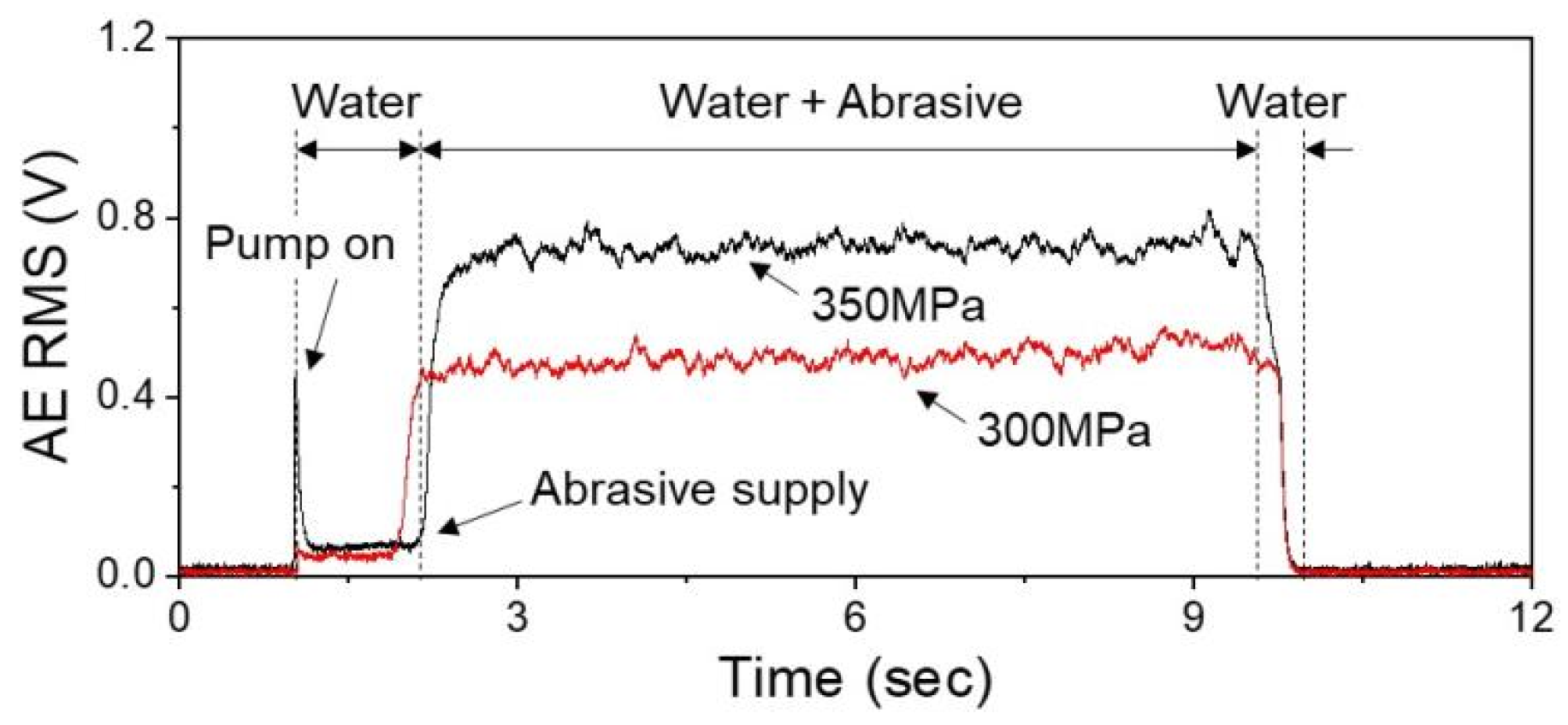
Figure 8 presents AE RMS values by waterjet pressure. Here, AE RMS was acquired for 12 s at a sampling rate of 1 KHz. When the high-pressure pump is turned on, water is first sprayed through the nozzle. A peak occurred at 1.5 s, when the water collided with the nozzle, but the AE RMS value was low when only water was supplied. When jets of high-pressure water and abrasive particles developed, the AE RMS values rapidly increased. The AE RMS values differed when high-pressure water and mixed jets were supplied, and when the machine stopped. Thus, if the AE RMS value drops to near 0 during machining, nozzle clogging or non-supply of abrasive particles is in play. The AE RMS value increased as the waterjet pressure increased because the speed of the abrasive particles and the number of collisions with the nozzle wall also increased.
Figure 9 presents the AE RMS values of normal, worn, and damaged nozzles by waterjet pressure and abrasive feed rate. At a pressure of 300 MPa (Figure 9a), the AE RMS values of new, 40 h, and 80 h nozzles remained near constant. In contrast, when the nozzle was used for 100 h, abrasion occurred, and the AE RMS value was about 0.2 V. At a waterjet pressure of 350 MPa (Figure 9b), the AE RMS value of the new nozzle was larger than that at 300 MPa, and remained around 0.45 V until 100 h. After that time, nozzle abrasion occurred, and the AE RMS value dropped to around 0.2 V. In particular, even if the processing conditions vary somewhat, the nozzle lifetime was 100 h. When the nozzle is damaged, the AE RMS values and the changes are large regardless of the processing conditions. The reason for this is that the energy imparted by collisions between the abrasive particles and the nozzle wall increases if the inside of the nozzle is damaged or the orifice and nozzle are misaligned, thereby making the flow of the mixed jet unstable and increasing the deviations and fluctuations of AE RMS values.
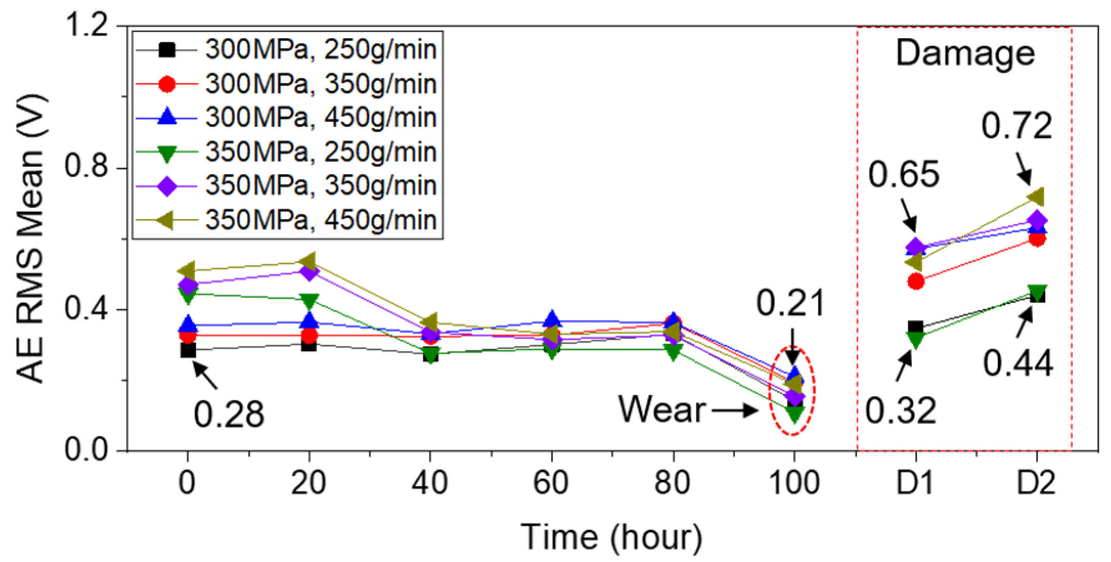
Figure 10 presents average AE RMS values by nozzle usage time when the waterjet pressure and abrasive feed rate varied. The waterjet pressures were 300 and 350 MPa, and the abrasive feed rates were 250, 350, and 450 g/min. At a waterjet pressure of 300 MPa, the average AE RMS value by the abrasive feed rate did not change significantly by nozzle usage time, but at 350 MPa, the AE RMS average value decreased after 20 h because the greater the waterjet pressure, the greater the collision energy between abrasive particles and the nozzle wall. Fine protrusions on the surface of a new nozzle wall are removed by abrasive particles. However, the average AE RMS value remained constant when surface wear commenced after the removal of such protrusions via continuous collisions with abrasive particles.
After 80 h, regardless of the waterjet pressure or abrasive feed rate, the nozzle wall wore slowly and began to expand. At this time, if nozzle expansion continues, the pressure inside the mixing head falls, as does the impact energy between abrasive particles and the nozzle surface, reducing the average AE RMS value. When the nozzle is damaged, the average value of the AE RMS is higher than that of a normal nozzle regardless of the usage time. The larger the abrasive feed rate, the greater the effect.

5. Summary and Conclusions

We developed a nozzle condition monitoring system based on the RMS values of an AE sensor. The system reveals the nozzle condition (normal, worn, damaged) in real time. In tests involving a commercial AWJ system and AE sensor setup, we measured and calculated nozzle AE RMS values while changing the waterjet pressure and the abrasive feed rate. We checked the nozzle status by usage time employing the AE RMS values and the average values.
Nozzle expansion caused by wear manifested as a change in the average AE RMS value detected in real time. The AE RMS value is proportional to the material removal rate (MRR). MRR reflecting nozzle wear manifests as an increase in nozzle diameter and a decrease in weight. Additionally, since the material removal energy is proportional to the AE energy, the nozzle status can be monitored based on changes in the AE RMS value. Unlike what is observed when nozzle wear slowly progresses, internal nozzle damage triggers a rapid increase in the AE RMS value [19,28]. The AE RMS value very effectively monitored nozzle wear and damage in real time. We measured AE RMS values after setting upper and lower limits to the average value (depending on the type of nozzle). One limitation is that the upper and lower limits of AE RMS values used were confirmed via experimental evaluation of nozzles from only one manufacturer. More research is needed to develop an algorithm that automatically determines upper and lower limits of AE RMS values. And the reliability of the AE sensor-mounting and sensor data acquisition method needs to be further improved through follow-up research. However, our findings confirm that a simple, real-time AE RMS nozzle monitoring system using the AE sensor will function well in the workshop.

Author Contributions

Conceptualization, J.-U.K., S.-R.K. and K.-C.L.; Data curation, R.-W.K.; Formal analysis, J.-U.K. and H.-H.K.; Funding acquisition, K.-C.L.; Investigation, J.-U.K. and H.-H.K.; Methodology, J.-U.K. and S.-R.K.; Project administration, S.-R.K.; Resources, R.-W.K.; Supervision, K.-C.L.; Validation, R.-W.K.; Visualization, J.-U.K.; Writing—original draft, J.-U.K.; Writing—review and editing, K.-C.L. All authors have read and agreed to the published version of the manuscript.

Funding

This work was supported by the National Research Foundation (NRF), South Korea, under Project BK21 FOUR (Smart Robot Convergence and Application Education Research Center).

Institutional Review Board Statement

Not applicable.

Informed Consent Statement

Not applicable.

Data Availability Statement

Not applicable.

Conflicts of Interest

The authors declare no conflict of interest.

References

  1. Hloch, S.; Valíček, J.; Kozak, D.; Tozan, H.; Chattopadhyaya, S.; Adamčík, P. Analysis of acoustic emission emerging during hydroabrasive cutting and options for indirect quality control. Int. J. Adv. Manuf. Technol. 2013, 66, 45–58. [Google Scholar] [CrossRef]
  2. Sutowski, P.; Sutowska, M.; Kapłonek, W. The use of high-frequency acoustic emission analysis for in-process assessment of the surface quality of aluminium alloy 5251 in abrasive waterjet machining. Proc. Inst. Mech. Eng. Part B J. Eng. Manuf. 2018, 232, 2547–2565. [Google Scholar] [CrossRef]
  3. Axinte, D.; Kong, M. An integrated monitoring method to supervise waterjet machining. CIRP Ann. 2009, 58, 303–306. [Google Scholar] [CrossRef]
  4. Liu, H.-T. “7M” Advantage of abrasive waterjet for machining advanced materials. J. Manuf. Mater. Processing 2017, 1, 11. [Google Scholar] [CrossRef] [Green Version]
  5. Liu, H.-T.; Gershenfeld, N. Performance comparison of subtractive and additive machine tools for meso-micro machining. J. Manuf. Mater. Processing 2020, 4, 19. [Google Scholar] [CrossRef]
  6. Phokane, T.; Gupta, K.; Gupta, M.K. Investigations on surface roughness and tribology of miniature brass gears manufactured by abrasive water jet machining. Proc. Inst. Mech. Eng. Part C J. Mech. Eng. Sci. 2018, 232, 4193–4202. [Google Scholar] [CrossRef]
  7. Liu, X.; Liang, Z.; Wen, G.; Yuan, X. Waterjet machining and research developments: A review. Int. J. Adv. Manuf. Technol. 2019, 102, 1257–1335. [Google Scholar] [CrossRef]
  8. Li, H. Monitoring the abrasive waterjet drilling of Inconel 718 and steel: A comparative study. Int. J. Adv. Manuf. Technol. 2020, 107, 3401–3414. [Google Scholar] [CrossRef]
  9. Krenicky, T.; Servatka, M.; Gaspar, S.; Mascenik, J. Abrasive Water Jet Cutting of Hardox Steels—Quality Investigation. Processes 2020, 8, 1652. [Google Scholar] [CrossRef]
  10. Sutowska, M.; Kapłonek, W.; Pimenov, D.Y.; Gupta, M.K.; Mia, M.; Sharma, S. Influence of Variable Radius of Cutting Head Trajectory on Quality of Cutting Kerf in the Abrasive Water Jet Process for Soda–Lime Glass. Materials 2020, 13, 4277. [Google Scholar] [CrossRef]
  11. Natarajan, Y.; Murugesan, P.K.; Mohan, M.; Khan, S.A.L.A. Abrasive Water Jet Machining process: A State of Art of Review. J. Manuf. Process. 2020, 49, 271–322. [Google Scholar] [CrossRef]
  12. Deaconescu, A.; Deaconescu, T. Response Surface Methods Used for Optimization of Abrasive Waterjet Machining of the Stainless Steel X2 CrNiMo 17-12-2. Materials 2021, 14, 2475. [Google Scholar] [CrossRef] [PubMed]
  13. Dixit, N.; Sharma, V.; Kumar, P. Research trends in abrasive flow machining: A systematic review. J. Manuf. Process. 2021, 64, 1434–1461. [Google Scholar] [CrossRef]
  14. Llanto, J.; Tolouei-Rad, M.; Vafadar, A.; Aamir, M. Impacts of Traverse Speed and Material Thickness on Abrasive Waterjet Contour Cutting of Austenitic Stainless Steel AISI 304L. Appl. Sci. 2021, 11, 4925. [Google Scholar] [CrossRef]
  15. Llanto, J.M.; Vafadar, A.; Aamir, M.; Tolouei-Rad, M. Analysis and Optimization of Process Parameters in Abrasive Waterjet Contour Cutting of AISI 304L. Metals 2021, 11, 1362. [Google Scholar] [CrossRef]
  16. Romanowski, M.; Łukianowicz, C.Z.; Sutowska, M.; Zawadka, W.; Pimenov, D.Y.; Nadolny, K. Assessment of the Technological Quality of X5CRNI18-10 Steel Parts after Laser and Abrasive Water Jet Cutting Using Synthetic Index of Technological Quality. Materials 2021, 14, 4801. [Google Scholar] [CrossRef]
  17. Krenicky, T.; Olejarova, S.; Servatka, M. Assessment of the Influence of Selected Technological Parameters on the Morphology Parameters of the Cutting Surfaces of the Hardox 500 Material Cut by Abrasive Water Jet Technology. Materials 2022, 15, 1381. [Google Scholar] [CrossRef]
  18. Demiral, M.; Abbassi, F.; Saracyakupoglu, T.; Habibi, M. Damage analysis of a CFRP cross-ply laminate subjected to abrasive water jet cutting. Alex. Eng. J. 2022, 61, 7669–7684. [Google Scholar] [CrossRef]
  19. Nguyen, T.; Wang, J. A review on the erosion mechanisms in abrasive waterjet micromachining of brittle materials. Int. J. Extreme Manuf. 2019, 1, 012006. [Google Scholar] [CrossRef] [Green Version]
  20. Vasanth, S.; Muthuramalingam, T.; Vinothkumar, P.; Geethapriyan, T.; Murali, G. Performance Analysis of Process Parameters on Machining Titanium (Ti-6Al-4V) Alloy Using Abrasive Water Jet Machining Process. Procedia CIRP 2016, 46, 139–142. [Google Scholar] [CrossRef] [Green Version]
  21. Pramanik, A. Developments in the non-traditional machining of particle reinforced metal matrix composites. Int. J. Mach. Tools Manuf. 2014, 86, 44–61. [Google Scholar] [CrossRef] [Green Version]
  22. Nanduri, M.; Taggart, D.G.; Kim, T.J. The effects of system and geometric parameters on abrasive water jet nozzle wear. Int. J. Mach. Tools Manuf. 2002, 42, 615–623. [Google Scholar] [CrossRef]
  23. Dolinšek, S.; Kopač, J. Acoustic emission signals for tool wear identification. Wear 1999, 225–229, 295–303. [Google Scholar] [CrossRef]
  24. Kovacevic, R. A new sensing system to monitor abrasive waterjet nozzle wear. J. Mater. Processing Technol. 1991, 28, 117–125. [Google Scholar] [CrossRef]
  25. Kovacevic, R.; Wang, L.; Zhang, Y.M. Identification of Abrasive Waterjet Nozzle Wear Based on Parametric Spectrum Estimation of Acoustic Signal. Proc. Inst. Mech. Eng. Part B J. Eng. Manuf. 1994, 208, 173–181. [Google Scholar] [CrossRef]
  26. Putza, M.; Dittricha, M.; Dixa, M. Process Monitoring of Abrasive Waterjet Formation. Procedia CIRP 2016, 46, 43–46. [Google Scholar] [CrossRef]
  27. Prabu, R.; Manivannan, A. Condition Monitoring of Focusing Nozzle in Abrasive Water Jet Machine using Sound Sensor. Indian J. Sci. Technol. 2017, 10, 1–12. [Google Scholar] [CrossRef] [Green Version]
  28. Kovacevic, R.; Momber, A.W.; Mohen, R.S. Energy Dissipation Control in Hydro-Abrasive Machining Using Quantitative Acoustic Emission. Int. J. Adv. Manuf. Technol. 2002, 20, 397–406. [Google Scholar] [CrossRef]
Figure 1. Schematic of the nozzle condition monitoring system using AE RMS values.
Jmmp 06 00031 g001
Figure 2. Experimental setup for the AWJ nozzle tests.
Jmmp 06 00031 g002
Figure 3. The program detecting wear, damage, and normal nozzle status.
Jmmp 06 00031 g003
Figure 4. Photographs of normal, expanded, and damaged nozzles at a waterjet pressure of 350 MPa and an abrasive feed rate of 450 g/min: (a) nozzle diameters and (b) cross-sectional shapes.
Jmmp 06 00031 g004
Figure 5. Nozzle bore diameters and weights at a waterjet pressure of 350 MPa and an abrasive feed rate of 450 g/min.
Jmmp 06 00031 g005
Figure 6. Photographs of parts by using normal and damaged nozzles: (a) normal part and (b) abnormal part.
Jmmp 06 00031 g006
Figure 7. Comparison of the AE raw signals and FFT analysis of new, worn, and damaged nozzles at a waterjet pressure of 300 MPa and an abrasive feed rate of 350 g/min: (a) AE raw signals and (b) FFT signals.
Jmmp 06 00031 g007
Figure 8. Comparison of AE RMS values as the waterjet pressure varies at 350 g/min of abrasive flow.
Jmmp 06 00031 g008
Figure 9. A comparison of the AE RMS values of new, worn, and damaged nozzles: (a) AE RMS values at a waterjet pressure of 300 MPa and an abrasive feed rate of 350 g/min, and (b) AE RMS values at a waterjet pressure of 350 MPa and an abrasive feed rate of 450 g/min.
Jmmp 06 00031 g009
Figure 10. Comparison of mean AE RMS values by waterjet pressure and abrasive feed rate.
Jmmp 06 00031 g010
Table 1. Experimental conditions.
ParameterValue
waterjet pressure, MPa300, 350
abrasive feed rate, kg/min250, 350, 450
abrasive material (mesh)Garnet #80
focusing nozzle length, mm101
focusing nozzle diameter, mm1.02
orifice diameter, mm0.33
nozzle use time, h0, 20, 40, 80, 100
Publisher’s Note: MDPI stays neutral with regard to jurisdictional claims in published maps and institutional affiliations.