Article

Influence of Surface Preparation on Cracking Phenomena in TIG-Welded High and Medium Entropy Alloys

1
Bundesanstalt für Materialforschung und-prüfung (BAM), Unter den Eichen 87, 12205 Berlin, Germany
2
Institute for Materials Science and Joining Technology, Otto-von-Guericke-University Magdeburg, Universitätsplatz 2, 39106 Magdeburg, Germany
*
Author to whom correspondence should be addressed.
J. Manuf. Mater. Process. 2022, 6(1), 5; https://doi.org/10.3390/jmmp6010005
Submission received: 1 November 2021 / Revised: 22 December 2021 / Accepted: 25 December 2021 / Published: 27 December 2021
(This article belongs to the Special Issue Advanced Joining Processes and Techniques)

Abstract

:
Multi-element systems with defined entropy (HEA—high entropy alloy or MEA—medium entropy alloy) are rather new material concepts that are becoming increasingly important in materials research and development. Some HEA systems show significantly improved properties or combinations of properties, e.g., the overcoming of the trade-off between high strength and ductility. Thus, the synthesis, the resulting microstructures, and properties of HEA have been primarily investigated so far. In addition, processing is crucial to achieve a transfer of potential HEA/MEA materials to real applications, e.g., highly stressed components. Since fusion welding is the most important joining process for metals, it is of vital importance to investigate the weldability of these materials. However, this has rarely been the subject of research to date. For that reason, in this work, the weldability depending on the surface preparation of a CoCrFeMnNi HEA and a CoCrNi MEA for TIG welding is investigated. The fusion welding of longer plates is described here for the first time for the CoCrNi alloy. The welds of both materials showed distinct formation of cracks in the heat affected zone (HAZ). Optical and scanning electron microscopy analysis clearly confirmed an intergranular fracture topography. However, based on the results, the crack mechanism cannot be conclusively identified as either a liquid metal embrittlement (LME) or hot cracking-like liquid film separation.

1. Introduction

High and medium entropy alloys (HEAs and MEAs) have steadily gained interest in worldwide research since their introduction [1,2,3]. In this work, HEAs and MEAs are defined as compositionally complex and disordered single-phase solid solutions containing two to four elements for MEAs and at least five elements for HEAs in nearly equiatomic proportions [4]. Due to their outstanding properties (e.g., high ductility combined with high strength), both HEAs and MEAs have the potential to replace conventional alloys such as Fe-based steels and are therefore promising for a wide range of applications [3,4,5]. The 3d-transition metal system (Co, Cr, Fe, Mn, Ni) is the most intensively examined so far [5,6]. At very low temperatures, the equiatomic CoCrFeMnNi HEA (called the “Cantor” alloy [2]) and the CoCrNi MEA [7,8] show outstanding mechanical properties [9,10]. Therefore, applications exposed to cryogenic conditions could be fields of application for these materials, such as liquified cryo gas storage tanks and pipes in the energy and chemical industries.
With a total of over 100 publications in 2021, the knowledge about weldability of HEAs is steadily increasing [11,12]. However, the practical welding processing of this alloy type is still largely unexplored. Factors such as the initial material condition [13], weld seam preparation in relation to surface condition (machined or eroded), weld seam geometry, and design have to be investigated. Even for high entropy alloys, it is known that the surface influencing processing steps can have a great influence on the final surface quality in terms of microstructure, residual stresses, and change of local microstructure or residuals or remaining contaminations on the surface [14,15]. These initial conditions can affect a material’s weldability as the interaction of the factor’s material, welding process, and design.
Meanwhile, it is established that CoCrFeMnNi HEAs have good weldability for fusion welding processes such as laser beam (LB), electron beam (EB), or tungsten inert-gas (TIG) welding [11]. The reason for the good weldability of CoCrFeMnNi HEAs is that no cracks or other weld imperfections, which are material related, have been described so far in the literature [13,16,17]. In contrast, the addition of Al or Cu in AlxCoCrCuyNi alloys significantly reduces the weldability and can lead to the formation of cracks, where x is from 0 to 17 at.% and y from 0 to 8.5 at.% [18,19]. In that case, the crack mechanism depends on the Cu content and changes from a brittle and transgranular fracture mode to an intergranular liquid film separation (hot cracking) in medium and higher Cu contents (y > 0.1) [19].
The literature shows that HEA and MEA offer great potential for various applications, but so far there are still many questions regarding processability. Therefore, this study focuses on the TIG welding of selected HEA (CoCrFeMnNi) and MEA (CoCrNi-first time TIG welding study) systems for thin sheets and investigates the influence of surface preparation.

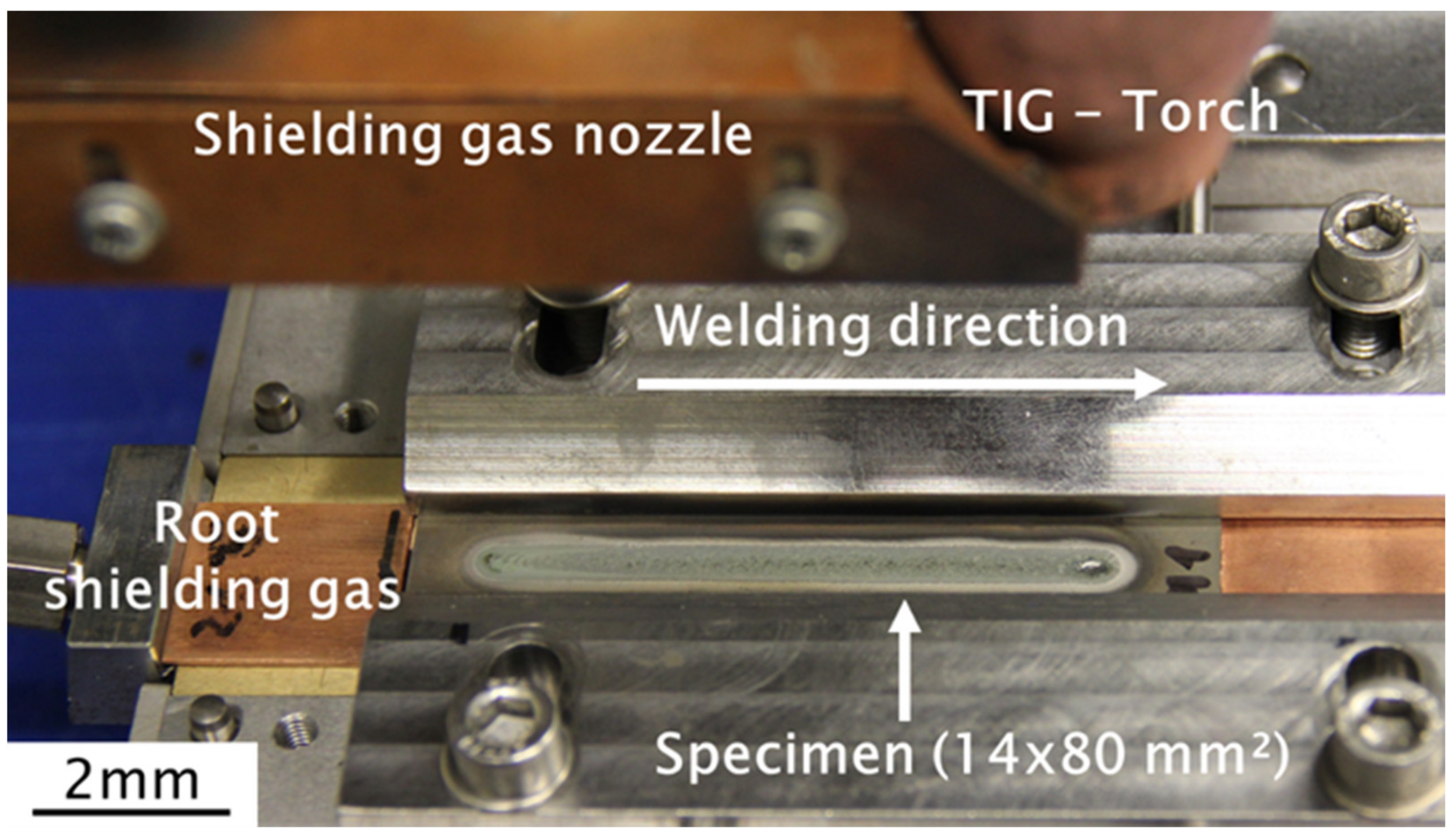
2. Materials and Methods

For the experiments, two different materials were investigated: Cr33.3Co33.3Ni33.3 MEA-system and Cr20Mn20Fe20Co20Ni20 HEA-system (both in at. %), both kindly synthesized by RU Bochum (Professor Laplanche). For that purpose, pure elements were used to produce inductively melted ingots in a high purity argon atmosphere. Subsequently, the ingots were homogenized at 1473 K for 48 h and rotationally swaged in seven steps to a cylinder with approximately 17 mm of diameter and a length of 100 mm. Final heat treatments (1 h at 1293 K for CoCrFeMnNi) and (1 h at 1333 K for CoCrNi) were performed to recrystallize the alloys and produce a similar grain size of approximately 50 µm for both alloys. The preparation of the single-phase FCC alloys [20,21] is described in more detail in [22,23,24]. The chemical composition of the ingots was determined by electron microprobe analysis (EMPA) in a JEOL JXA-8900-RL system and by spot measurements at 50 different locations per sample. The results are shown in Table 1. Hardness measurements (see also Table 1) were performed according to DIN EN ISO 6507-1 [25]; the reported values are the average of 12 measuring points. Light optical images of the single-phase FCC microstructures are given for both base materials in Figure 1. The specimens were embedded in epoxy-based, ground with 1200 grit paper and finally diamond-polished (grit size 1 µm). The etching was performed using Beraha-II etchant for 15 s at room temperature. There are dark particles in both alloys, which are CrMn-oxides (CoCrFeMnNi) [26] and Cr-oxides (CoCrNi) [9], respectively, which originate from the material production.
For the welding experiments, 1 mm thick plates with dimensions 14 × 82 mm2 were cut from the recrystallized ingots by electrical discharge machining (EDM) using an AP 450L from SODICK and a brass (Cu63Zn37) wire. Subsequently, two welding tests were performed for each alloy. One sample remained in “as-machined” EDM condition; the other was additionally ground (SiC 600 grit paper). The idea was to investigate the influence of the different surface preparation conditions on the weldability as surface contaminations perhaps alter the results (see Section 1). Prior to the welding tests, the surfaces were cleaned with ethanol to remove organic compound residuals such as grease. The TIG welding experiments were carried out using a specially designed and custom-made manufactured specimen clamping system for the small specimens. The complete test setup is shown in Figure 2. Here, in addition to the TIG torch, a gas trailing nozzle can be seen to cover the weld metal even after welding. The same applies to the root, which is to be protected from oxidation by means of shielding gas. For welding, a Polysoude PC 600 TIG system with the data given in Table 2 was used, ensuring a remelted bead-on-plate-like weld seam with approximately 70 mm length. The experimental parameters were determined using a single-phase FCC Ni-base alloy (2.4858), since these have comparable thermophysical properties and only little HEA and MEA material is available.
For the light optical microscopic (LOM) examination, cross sections were prepared, ground and polished with diamond paste to 1 µm grain size. This was followed by etching with Beraha II etchant. The light microscope used was a POLYVAR MET from Reichert-Jung. The SEM images and EDX measurements were performed on a Phenom XL from Thermo Fisher Scientific. The radiographic tests were performed according to DIN EN ISO 17636-1 [27] with a titanium 420 X-ray source. The energy of the radiation was 100 kV with a film-focus distance of 1000 mm. The achieved resolution of the film used at these settings was 50 μm.
Micro Computed Tomography (µCT) measurements were carried out on a GE v|tome|x 180/300 L system. The reflection target was used with an applied acceleration voltage of 200 kV and a tube current of 40 µA, resulting in 8 W tube power. A flat panel detector (2024 × 2024 Pixel) was used with a pixel pitch of 200 µm. The source to object distance (SOD) was 20 mm and the source to detector distance (SDD) was 500 mm. This yielded a magnification of 25× and therefore a reconstructed voxel size of 8 µm and a field of view (FOV) of 16 x 16 mm. Transmission images at 2400 angles were acquired. For each angle, four projections at 1 s counting time were averaged. These projections were used to reconstruct the 3D volume using the filtered back projection algorithm [28] embedded in the reconstruction software of GE.

3. Results

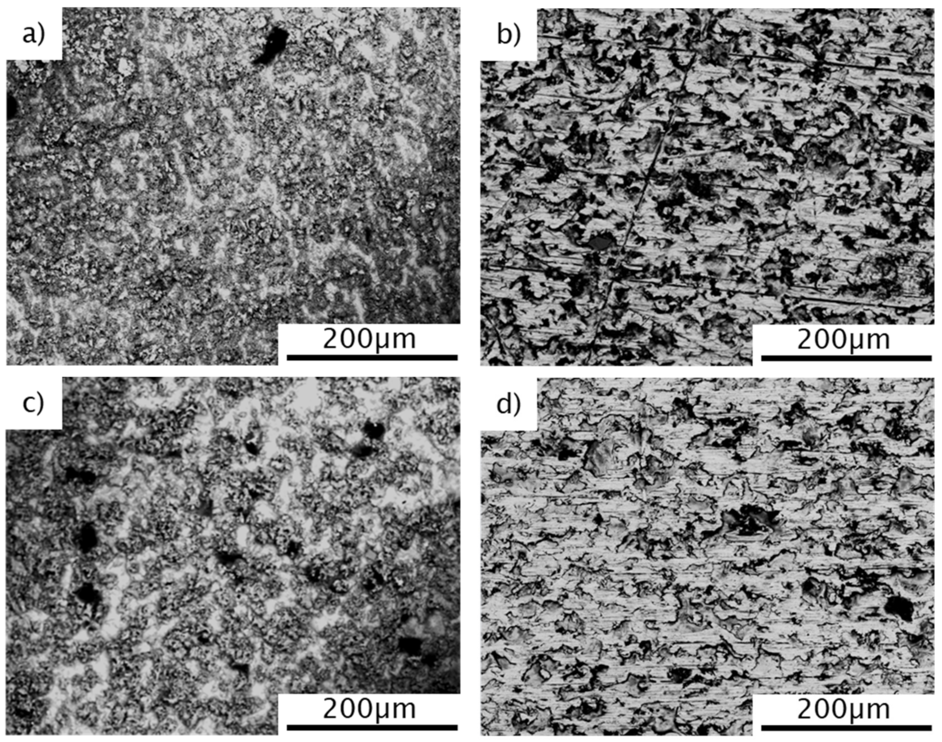
3.1. Surface Characterization

In order to determine the influence of the surface preparation on the welding process, the surfaces were characterized before. Figure 3 shows SEM images of the surfaces after EDM (parts a,c) and additional grinding (parts b,d) of the HEA and MEA. Both alloys show clear bright deposits on the surface after EDM (see Figure 3a,c). These were removed by further grinding and were not visible anymore but show grinding grooves without directional orientation (see Figure 3b,d). The corresponding chemical composition of the surface areas (corresponding Figure 3) was investigated by EDX-mapping and is shown in Table 3. It can be seen that, only in the case of the EDM-prepared surface, significant amounts of Cu and Zn deposits can be found on the surfaces. This is due to electrical and electrochemical dissolution of the brass wire used, as EDM also requires an additional purging electrolyte to (a) set the electric connection between wire and workpiece and (b) to remove the eroded particles from the surface [29]. The ground surfaces show a composition close to the target composition without any Cu or Zn containing deposits.

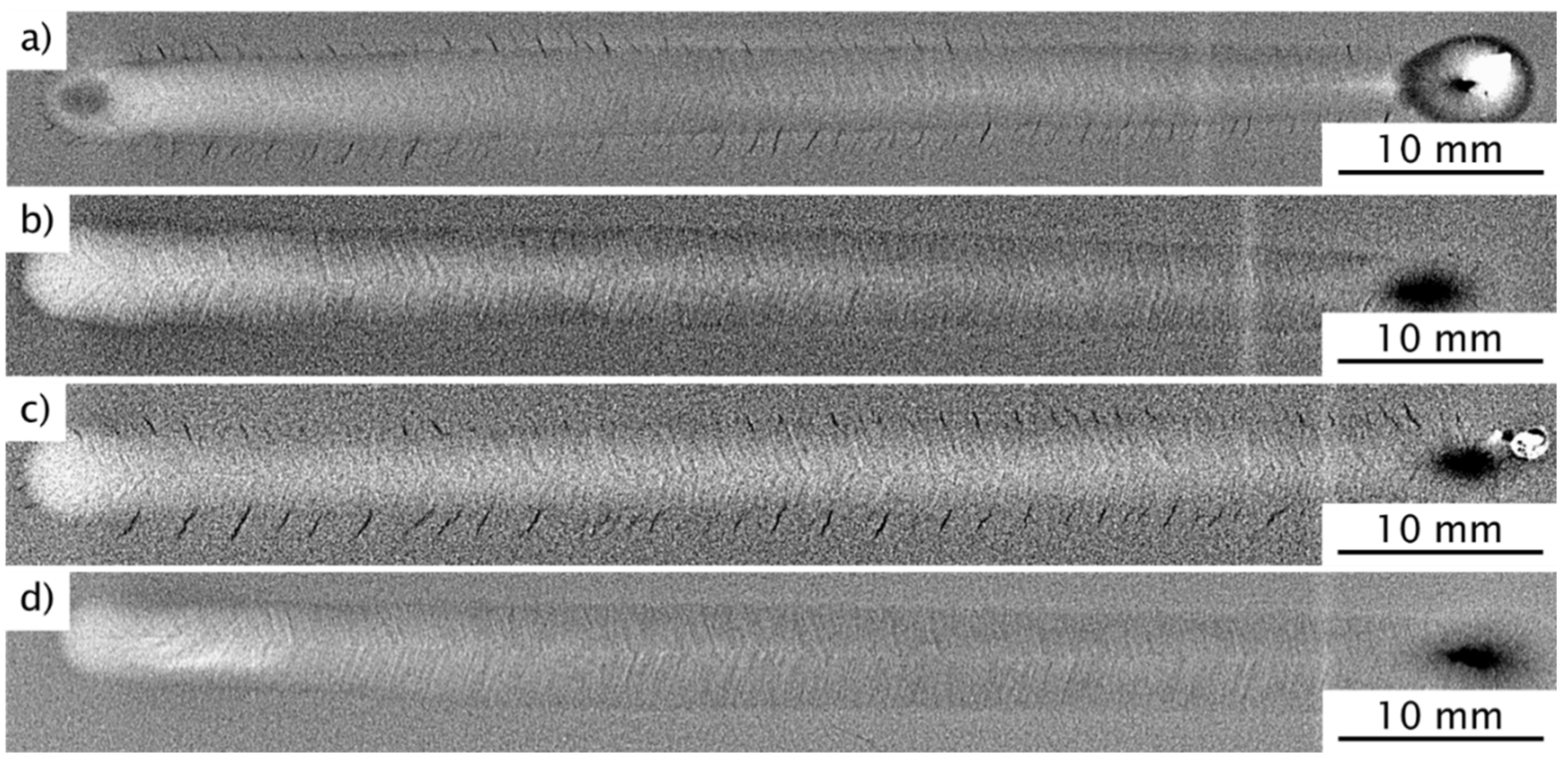
3.2. Results of the Radiographic Tests

In order to detect possible inner weld imperfections such as pores or cracks, a radiographic inspection was performed after welding. The results are shown in Figure 4. The welds with eroded surface show clear cracks in the HAZ along the entire weld length for both CoCrFeMnNi HEA (Figure 4a) and CoCrNi MEA (Figure 4c). These run at approximately 45° from the fusion line in the opposite direction to the welding direction. In contrast, the images of the welds with ground surface do not show any obvious weld imperfections after radiographic inspection (Figure 4b,c). Moreover, these results from identical welding tests with different surface preparations clearly show that EDM surfaces lead to cracks in the HAZ, which can be avoided by additional grinding. Consequently, the surface preparation has a significant influence on the weldability of HEAs and MEAs. In the following, the cracking mechanism will be clarified.

3.3. Light Optical Microscopy

The assumption that no other weld imperfections are present (except for the cracks on the eroded specimens, see Figure 4a,c) is confirmed by the cross sections in Figure 5a–d. These also show full weld penetration for all welds without any seam sag, which demonstrates that the welding parameters were suitable. Furthermore, a dendritic solidification of the weld metal can be seen. In the HAZ, hardly any influence on the microstructure in terms of grain growth of the recrystallized base material is evident.
Further details of the obtained cracks are presented with higher magnification in Figure 5e (HEA) and Figure 5f (MEA). Here, an intergranular characteristic of the cracks in the CoCrNi MEA and the CoCrFeMnNi HEA can be clearly seen. At the crack flanks of the CoCrFeMnNi HEA, brightness differences to the directly adjacent grain occur in some cases (counter-drawn in the white box in Figure 5e,f). In the case of CoCrNi MEA, changes also occur on the crack flanks compared to the surrounding material (marked in the white box). This difference on the crack flanks may indicate the presence of another phase. Otherwise, these effects can also occur due to inconsistent etching or edge effects. Intergranular cracks in the HAZ can be due to a large variety of crack mechanisms. On the one hand, it could be conventional hot cracking in the form of liquation cracks or ductility dip cracks (DDC) [30]. On the other hand, the cracks could also be initiated by a liquid metal embrittlement (LME) mechanism, which mainly occurs in, e.g., Zn-coated materials [31,32]. Cold cracking can be ruled out since both alloys have an increased elongation at fracture at temperatures below 400 °C [33] and, in addition, the CoCrFeMnNi alloy does not tend to strong hydrogen-induced embrittlement [34].

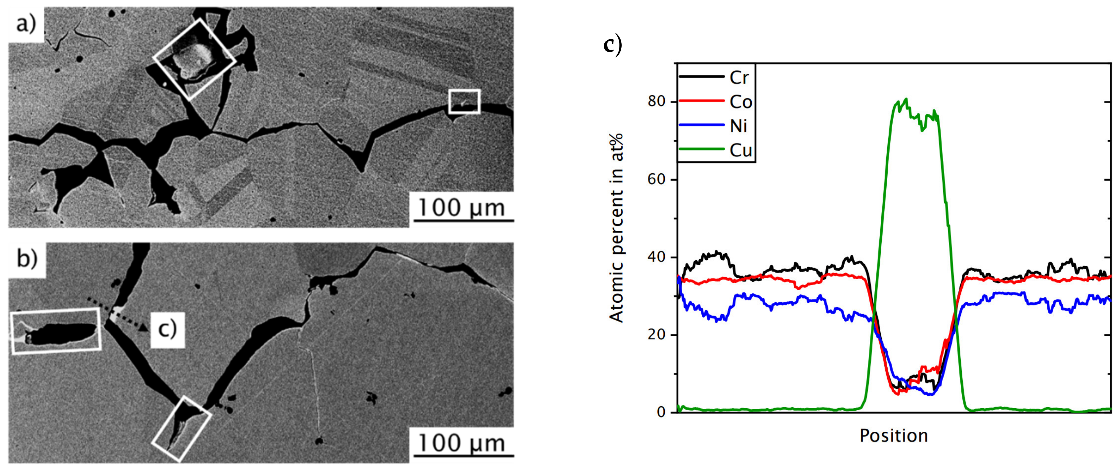
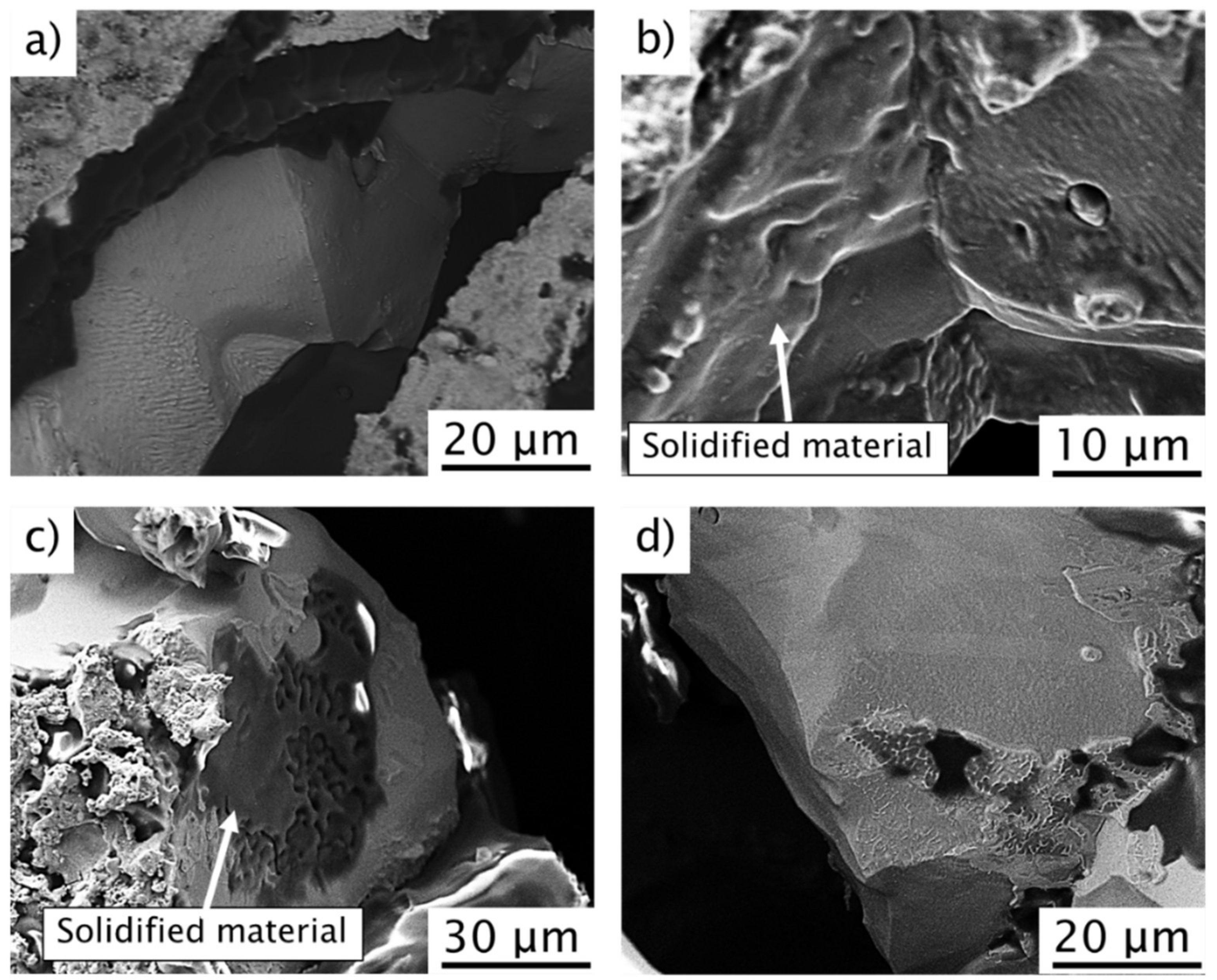
3.4. Crack Characterization via SEM and EDX

In this section, results of SEM and EDX investigations of the cracks and possible deposits on the crack flanks are presented. Figure 6a,b confirms the descripted effects from Section 3.3, as bright layers (in the white boxes) on the cracks of both alloys are clearly visible (image by BSD detector of SEM). The occurrence of another phase in this case would correlate with the conjectures described previously. Since the intensity of the backscattered electrons increases with the atomic weight, i.e., of the irradiated elements, in SEM investigations [35], these brighter areas in the images indicate a changed chemical composition on the crack flanks and grain boundaries, which, on average, contains elements of a higher order. Further examination was conducted by EDX line scans of the area marked in Figure 6b. The results are shown in Figure 6c. It is clearly visible that this region is enriched in copper compared to surrounding material. Since there is no copper in the base material, it must inevitably be molten copper from the EDM, which was liquefied at the elevated welding temperatures. It is assumed that the copper diffused or flowed into the crack as a liquid phase due to capillary forces, since the cracks are reaching from the fusion line to the specimen surfaces. However, the exact mechanism cannot be conclusively clarified due to a lack of knowledge and information in the area of research in connection with Cu diffusion in HEA or MEA materials. Therefore, these assumptions will be related to the cracking mechanisms and discussed further below.
The examinations of the crack surface (Figure 7) show, as well as the cross sections in Figure 5 and Figure 6, an intergranular fracture surface. In addition, both materials show solidification morphologies on the individual grain boundaries in Figure 7b,c. In addition, the lighter copper deposits are clearly visible in the cracks of CoCrNi (Figure 7c,d), although this cannot be detected by EDX due to the position in the crack.
In order to verify the assumption of LME occurrence, µCT scans were performed on the weld of the CoCrFeMnNi HEA. For that reason, three different positions (virtual cross section positions) through the reconstructed volume are shown in Figure 8.
The results of the µCT indicate that the cracks are larger in shape and number on the surfaces (Figure 8b,d) than in the specimen center (Figure 8c). In addition, the cracks on the top side are also larger and wider as compared to the root side. One reason should be related to higher shrinkage stresses due to wider weld shape at the top compared to the root side. These results support the assumption of the LME mechanism, since the cracks are in contact with the surface and thus with the CuZn deposits on the as-machined EDM surface. In addition, the CuZn-deposit melting temperature (Ts ~ 910 °C [36]) is way below that of the HEA (Ts = 1289 °C [37]) and MEA (Ts = 1417 °C [7]). Furthermore, these CuZn-compounds are more pronounced on the weld seam top side, since here the temperature introduced by the arc column is higher than on the root side (heat conduction through the material) and, thus, the effect for the occurrence or probability of LME is increased.

4. Discussion

The results of the TIG welding of CoCrFeMnNi HEA and CoCrNi MEA show that cracks form in the HAZ depending on the surface preparation. These cracks appear only at EDM cut samples in “as-machined” condition and are successfully avoided by additional grinding of the EDM surfaces. Figure 9 schematically shows a comparison of the two presumed mechanisms, liquation cracking and LME, which are discussed in more detail below.
CuZn deposits are present on the surface before welding (Figure 9a) caused by EDM, as described in Section 3.1. During welding, temperatures significantly above the melting temperature of Cu63Zn37 (~910 °C [36]) are reached in the HAZ, causing melting and subsequent penetration of liquid CuZn deposits into the grain boundaries (see Figure 9b).
As shown in Figure 9c, for the mechanism of liquation cracks, this penetration may cause CuZn-rich phases to form at the grain boundaries, which become molten due to the elevated temperatures during welding. The grain boundaries then cannot endure the mechanical stresses from the welding-induced shrinkage of the clamped specimen, leading to material separation. It is assumable that this also acts as a crack initiation mechanism directly at the fusion line, and that further crack propagation is more likely to be due to the notch effect of the initial crack.
Note that welding stresses or the residual stress state were not further investigated, as it is assumed that welding stress evolution is regardless of the surface preparation and should be comparable in the crack free (ground) specimens. It is also assumed that the load due to shrinkage stress, especially in weld direction, is then high enough to cause the separation of the grains either due to the liquid phase or due to embrittlement at the grain boundaries.
Figure 9d shows the cracking mechanism for LME, which would be likely for the EDM surfaces [32,38,39,40]. Note that the exact LME mechanism has not yet been conclusively clarified. However, the evidence provides numerous requirements and preconditions for this: the presence of a mechanical or thermal load, a solid metal, and an embrittling liquid phase. Additionally, interactions such as wetting by the liquid metal and an associated contact with the solid material do play an important role here. However, properties of the solid material, the chemical composition, grain size, and external process-related variables, e.g., temperature and exposure time, do also have significant influence on LME. Therefore, detailed statements are difficult to make based on the present results and require further research, also because the derivation of statements from results and studies by other authors on the LME system between CuZn and HEA and MEA are not yet available. It should also be taken into account that it cannot be excluded that diffusion of CuZn dissolved in the weld metal at the HAZ contributes to crack initiation and growth.
The assumption of LME as crack mechanism is based on (i) the avoidance of these cracks by removing the brass layer from the surface, (ii) the distinct intergranular crack propagation with deposits of melted material from the brass layer, and (iii) the location of the cracks on the surfaces of the sheets. Furthermore, (iv) the crack shape and the Cu deposits on the crack flanks (see Figure 5 and Figure 6) on both materials indicate LME [32,38]. According to Savage et al., LMEs can be caused by copper deposits, especially in metals with FCC structure [39,40].
Alternatively, cracking could be intergranular liquid film separation due to penetration and/or diffusion of Cu and Zn along the grain boundaries, close to the fusion line. A phase with a low melting temperature is then formed and liquefied, as shown in [18,19]. Based on the presented results, the exact classification to one crack mechanism remains open and should be further clarified in future investigations. However, to completely rule out hot cracking, hot crack tests such as the programmable deformation-crack (PVR) test [41], could be performed to analyze the hot cracking sensitivity of these materials.

5. Conclusions

Weld experiments had been carried out for weldability of CoCrFeMnNi HEA and CoCrNi MEA. For that purpose, bead-on-plate-like remelting experiments were performed. The initial condition for the weldability had been additionally influenced by two different machining conditions in terms of EDM as-machined and further grinding of the samples’ surface. The obtained weld seams had been investigated by radiographic and metallographic methods supported by EDX and SEM analysis of the cracks, including a µCT reconstruction of the sample. The following findings can be concluded from the results:
(1)
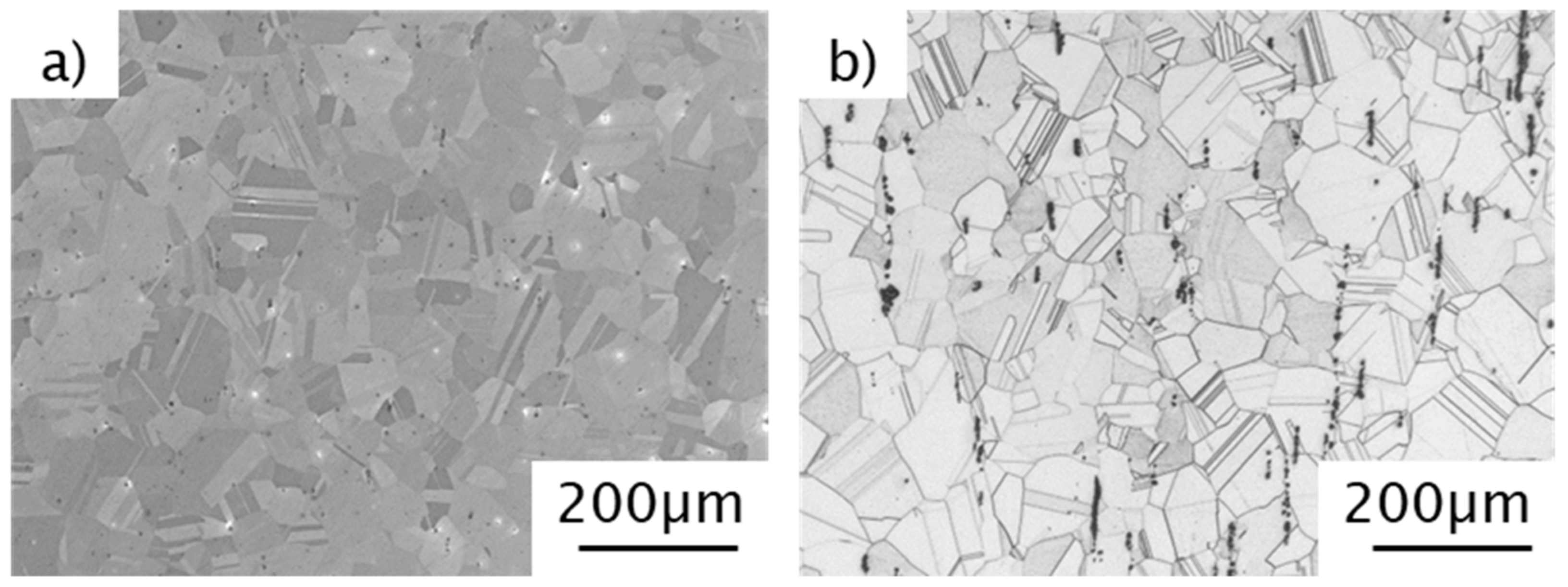
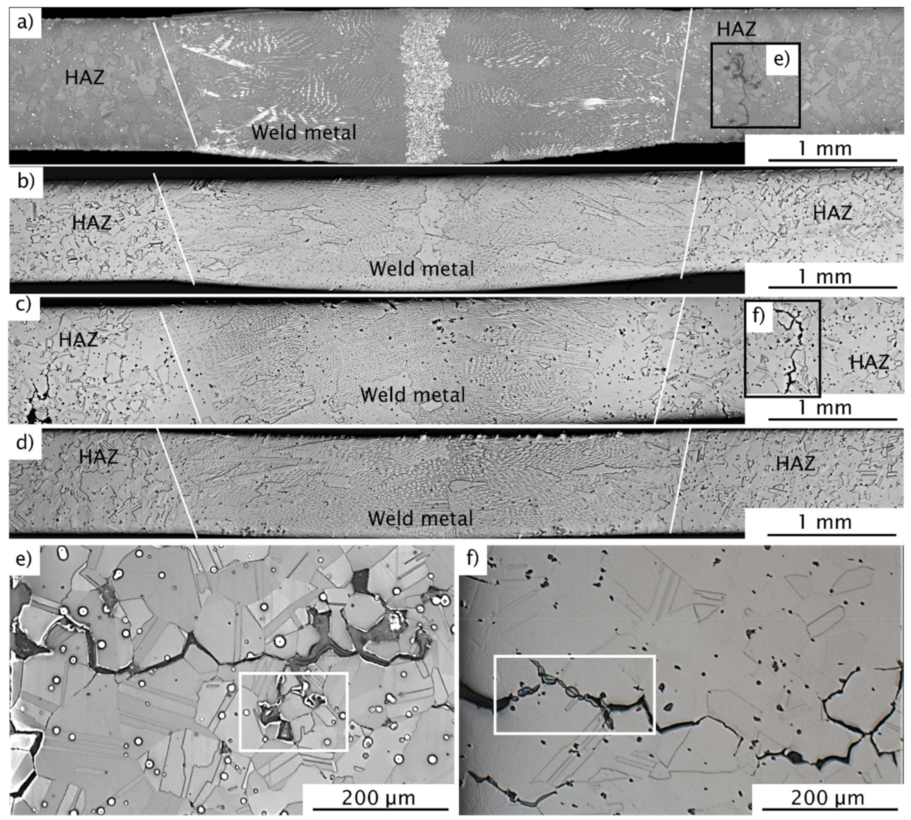
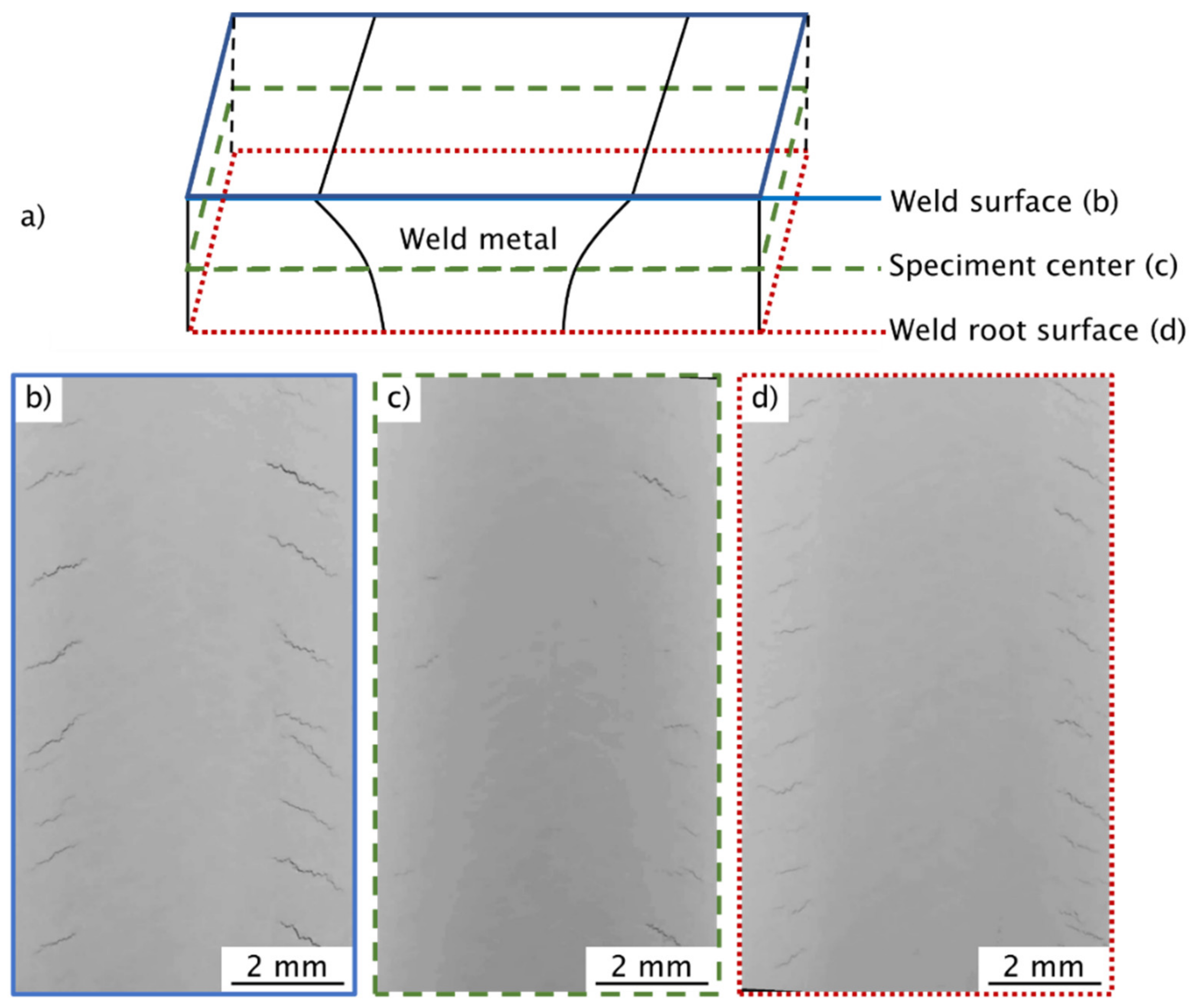
Both alloys, regardless of surface preparation, show a full weld penetration and a dendritic microstructure in the weld metal. The HAZ, on the other hand, shows no microstructural influence due to welding based on the results. The CoCrFeMnNi HEA and the CoCrNi MEA with ground surface have good TIG weldability, i.e., defect-free weld joints were obtained. The welded joints showed a dendritic in the weld center that originated from epitaxial growth from the fusion line and (as suggested by the experiments) an HAZ without a changed grain size compared to the base material.
(2)
In both alloys with as-machined EDM surfaces, cracks form in the HAZ, which can be avoided by grinding before welding. It can be concluded that the surface preparation has a significant influence on the weldability of HEAs and MEAs. The HEA and MEA have good weldability with a ground surface and poor weldability with an EDM machined surface.
(3)
Based on the results, an LME mechanism due to CuZn depositions is assumed to be the origin for the cracking, but this cannot be finally clarified, as intergranular liquid film separation could also be involved.

Author Contributions

Conceptualization, T.R., M.R., M.G. and D.S.; methodology, T.R., T.M. and T.F.; validation, T.R., M.R. and D.S.; formal analysis, T.R.; investigation, T.R.; data curation, T.R. and T.F.; writing—original draft preparation, T.R.; writing—review and editing, M.R. and D.S.; visualization, T.R., M.G. and T.F.; supervision, M.R. and D.S.; project administration, T.R.; funding acquisition, M.R. and D.S. All authors have read and agreed to the published version of the manuscript.

Funding

This research was funded by the SURDIA “Surface Degradation Phenomena and Utilization of Innovative Alloys” project of the Federal Institute for Materials Research and Testing (BAM).

Data Availability Statement

The data presented in this study are available on request from the corresponding author.

Acknowledgments

The authors would like to express their sincere thanks to Guillaume Laplanche and Mike Schneider of Ruhr University (RU) Bochum for providing the HEA and MEA materials. In addition, we would like to thank Marcel Grunwald from Bundesanstalt für Materialforschung und-prüfung BAM for Radiographic Techniques for performing the radiographic tests.

Conflicts of Interest

The authors declare no conflict of interest.

References

  1. Yeh, J.-W.; Chen, S.K.; Lin, S.-J.; Gan, J.-Y.; Chin, T.-S.; Shun, T.-T.; Tsau, C.-H.; Chang, S.-Y. Nanostructured High-Entropy Alloys with Multiple Principal Elements: Novel Alloy Design Concepts and Outcomes. Adv. Eng. Mater. 2004, 6, 299–303. [Google Scholar] [CrossRef]
  2. Cantor, B.; Chang, I.T.H.; Knight, P.; Vincent, A.J.B. Microstructural development in equiatomic multicomponent alloys. Mater. Sci. Eng. A 2004, 375–377, 213–218. [Google Scholar] [CrossRef]
  3. Miracle, D.B.; Senkov, O.N. A critical review of high entropy alloys and related concepts. Acta Mater. 2017, 122, 448–511. [Google Scholar] [CrossRef] [Green Version]
  4. Manzoni, A.; Glatzel, U. High-entropy alloys: Balancing strength and ductility at room temperature. In Encyclopedia of Materials, Science and Technology; Elsevier: Amsterdam, The Netherlands, 2020. [Google Scholar] [CrossRef]
  5. George, E.; Curtin, W.; Tasan, C. High entropy alloys: A focused review of mechanical properties and deformation mechanisms. Acta Mater. 2020, 188, 435–474. [Google Scholar] [CrossRef]
  6. Schneider, M.; Laplanche, G. Effects of temperature on mechanical properties and deformation mechanisms of the equiatomic CrFeNi medium-entropy alloy. Acta Mater. 2021, 204, 116470. [Google Scholar] [CrossRef]
  7. Wu, Z.; Bei, H.; Otto, F.; Pharr, G.; George, E. Recovery, recrystallization, grain growth and phase stability of a family of FCC-structured multi-component equiatomic solid solution alloys. Intermetallics 2014, 46, 131–140. [Google Scholar] [CrossRef]
  8. Wu, Z.; Bei, H.; Pharr, G.M.; George, E.P. Temperature dependence of the mechanical properties of equiatomic solid solution alloys with face-centered cubic crystal structures. Acta Mater. 2014, 81, 428–441. [Google Scholar] [CrossRef]
  9. Laplanche, G.; Kostka, A.; Reinhart, C.; Hunfeld, J.; Eggeler, G.; George, E.P. Reasons for the superior mechanical properties of medium-entropy CrCoNi compared to high-entropy CrMnFeCoNi. Acta Mater. 2017, 128, 292–303. [Google Scholar] [CrossRef]
  10. Liu, X.; Laplanche, G.; Kostka, A.; Fries, S.; Pfetzing-Micklich, J.; Liu, G.; George, E. Columnar to equiaxed transition and grain refinement of cast CrCoNi medium-entropy alloy by microalloying with titanium and carbon. J. Alloy Compd. 2019, 775, 1068–1076. [Google Scholar] [CrossRef]
  11. Rhode, M.; Richter, T.; Schroepfer, D.; Manzoni, A.M.; Schneider, M.; Laplanche, G. Welding of high-entropy alloys and compositionally complex alloys—An overview. Weld. World 2021, 65, 1645–1659. [Google Scholar] [CrossRef]
  12. Lopes, J.; Oliveira, J.P. A Short Review on Welding and Joining of High Entropy Alloys. Metals 2020, 10, 212. [Google Scholar] [CrossRef] [Green Version]
  13. Nam, H.; Park, S.; Chun, E.-J.; Kim, H.; Na, Y.; Kang, N. Laser dissimilar weldability of cast and rolled CoCrFeMnNi high-entropy alloys for cryogenic applications. Sci. Technol. Weld. Join. 2020, 25, 127–134. [Google Scholar] [CrossRef]
  14. Guo, J.; Goh, M.; Zhu, Z.; Lee, X.; Nai, M.L.S.; Wei, J. On the machining of selective laser melting CoCrFeMnNi high-entropy alloy. Mater. Des. 2018, 153, 211–220. [Google Scholar] [CrossRef]
  15. Richter, T.; Schröpfer, D.; Rhode, M.; Börner, A. Influence of Modern Machining Processes on the Surface Integrity of High-Entropy Alloys, Symposium on Materials and Joining Technology; IOP Publishing: Bristol, UK, 2020. [Google Scholar] [CrossRef]
  16. Oliveira, J.P.; Curado, T.M.; Zeng, Z.; Lopes, J.G.; Rossinyol, E.; Park, J.M.; Schell, N.; Fernandes, F.M.B.; Kim, H.S. Gas tungsten arc welding of as-rolled CrMnFeCoNi high entropy alloy. Mater. Des. 2020, 189, 108505. [Google Scholar] [CrossRef]
  17. Nam, H.; Park, C.; Kim, C.; Kim, H.; Kang, N. Effect of post weld heat treatment on weldability of high entropy alloy welds. Sci. Technol. Weld. Join. 2018, 23, 420–427. [Google Scholar] [CrossRef]
  18. Martin, A.C.; Fink, C. Initial weldability study on Al0.5CrCoCu0.1FeNi high-entropy alloy. Weld. World 2019, 63, 739–750. [Google Scholar] [CrossRef]
  19. Martin, A.C.; Oliveira, J.P.; Fink, C. Elemental Effects on Weld Cracking Susceptibility in AlxCoCrCuyFeNi High-Entropy Alloy. Met. Mater. Trans. A 2019, 51, 778–787. [Google Scholar] [CrossRef]
  20. Laplanche, G.; Gadaud, P.; Bärsch, C.; Demtröder, K.; Reinhart, C.; Schreuer, J.; George, E. Elastic moduli and thermal expansion coefficients of medium-entropy subsystems of the CrMnFeCoNi high-entropy alloy. J. Alloy Compd. 2018, 746, 244–255. [Google Scholar] [CrossRef]
  21. Laplanche, G.; Horst, O.; Otto, F.; Eggeler, G.; George, E. Microstructural evolution of a CoCrFeMnNi high-entropy alloy after swaging and annealing. J. Alloy Compd. 2015, 647, 548–557. [Google Scholar] [CrossRef]
  22. Richter, T.; Schroepfer, D.; Rhode, M.; Boerner, A.; Neumann, R.S.; Schneider, M.; Laplanche, G. Influence of machining on the surface integrity of high- and medium-entropy alloys. Mater. Chem. Phys. 2022, 275, 125271. [Google Scholar] [CrossRef]
  23. Schneider, M.; Werner, F.; Langenkämper, D.; Reinhart, C.; Laplanche, G. Effect of Temperature and Texture on Hall–Petch Strengthening by Grain and Annealing Twin Boundaries in the MnFeNi Medium-Entropy Alloy. Metals 2019, 9, 84. [Google Scholar] [CrossRef] [Green Version]
  24. Schneider, M.; George, E.P.; Manescau, T.J.; Záležák, T.; Hunfeld, J.; Dlouhý, A.; Eggeler, G.; Laplanche, G. Analysis of strengthening due to grain boundaries and annealing twin boundaries in the CrCoNi medium-entropy alloy. Int. J. Plast. 2020, 124, 155–169. [Google Scholar] [CrossRef]
  25. Metallische Werkstoffe–Härteprüfung nach Vickers–Teil 1: Prüfverfahren (ISO 6507-1:2018); Beuth Verlag GmbH: Berlin, Germany, 2018.
  26. Laplanche, G.; Volkert, U.F.; Eggeler, G.; George, E. Oxidation Behavior of the CrMnFeCoNi High-Entropy Alloy. Oxid. Met. 2016, 85, 629–645. [Google Scholar] [CrossRef]
  27. DIN. DIN EN ISO 17636-1:2013-05: Zerstörungsfreie Prüfung von Schweißverbindungen-Durchstrahlungsprüfung-Teil 1: Röntgen- und Gammastrahlungstechniken mit Filmen; Beuth Publishing DIN: Berlin, Germany, 2013. [Google Scholar]
  28. Feldkamp, L.A.; Davis, L.C.; Kress, J.W. Practical Cone-Beam Algorithm. J. Opt. Soc. Am. A 1984, 1, 612–619. [Google Scholar] [CrossRef] [Green Version]
  29. Springer Handbook of Mechanical Engineering; Springer Nature Switzerland AG: Cham, Switzerland, 2021.
  30. Böllinghaus, T.; Herold, H.; Cross, C.E.; Lippold, J.C. Hot Cracking Phenomena in Welds II; Springer: Berlin/Heidelberg, Germany, 2008. [Google Scholar]
  31. Kim, Y.G.; Kim, I.J.; Kim, J.S.; Chung, Y.I.; Choi, D.Y. Evaluation of Surface Crack in Resistance Spot Welds of Zn-Coated Steel. Mater. Trans. 2014, 55, 171–175. [Google Scholar] [CrossRef] [Green Version]
  32. Murugan, S.P.; Jeon, J.B.; Ji, C.; Park, Y.-D. Liquid zinc penetration induced intergranular brittle cracking in resistance spot welding of galvannealed advanced high strength steel. Weld. World 2020, 64, 1957–1969. [Google Scholar] [CrossRef]
  33. Otto, F.; Dlouhý, A.; Somsen, C.; Bei, H.; Eggeler, G.; George, E.P. The influences of temperature and microstructure on the tensile properties of a CoCrFeMnNi high-entropy alloy. Acta Mater. 2013, 61, 5743–5755. [Google Scholar] [CrossRef] [Green Version]
  34. Zhao, Y.; Lee, D.-H.; Seok, M.-Y.; Lee, J.-A.; Phaniraj, M.; Suh, J.-Y.; Ha, H.-Y.; Kim, J.-Y.; Ramamurty, U.; Jang, J.-I. Resistance of CoCrFeMnNi high-entropy alloy to gaseous hydrogen embrittlement. Scr. Mater. 2017, 135, 54–58. [Google Scholar] [CrossRef]
  35. Hornbogen, E.; Warlimont, H.; Skrotzki, B. Metalle; Springer-Verlag GmbH Deutschland: Berlin, Germany, 2019. [Google Scholar]
  36. Korobenko, V.N.; Savvatimski, A.I. The electrical resistance and enthalpy of industrial alloys based on nickel and copper. J. Non-Cryst. Solids 1996, 207, 678–682. [Google Scholar] [CrossRef]
  37. Chen, B.-R.; Yeh, A.-C.; Yeh, J.-W. Effect of one-step recrystallization on the grain boundary evolution of CoCrFeMnNi high entropy alloy and its subsystems. Sci. Rep. 2016, 6, 22306. [Google Scholar] [CrossRef] [Green Version]
  38. Mahmud, K.; Murugan, S.P.; Cho, Y.; Ji, C.; Nam, D.; Park, Y.-D. Geometrical degradation of electrode and liquid metal embrittlement cracking in resistance spot welding. J. Manuf. Process. 2021, 61, 334–348. [Google Scholar] [CrossRef]
  39. Savage, W.F.; Nippes, E.F.; Mushala, M.C. Copper-Contamination Cracking in the Weld Heat-Affected Zone. Weld. Res. Suppl. 1978, 5, 145–152. [Google Scholar]
  40. Savage, W.F.; Nippes, E.F.; Mushala, M.C. Liquid-Metal Embrittlement of the Heat-Affected Zone by Copper Contamination The mechanism responsible for copper-contamination hot cracking in the weld heat-affected zone is identified as liquidmetal embrittlement. Weld. Res. Suppl. 1978, 8, 237–245. [Google Scholar]
  41. Fink, C.; Zinke, M.; Jüttner, S. An investigation of ductility-dip cracking in the base metal heat-affected zone of wrought nickel base alloys—part II: Correlation of PVR and STF results. Weld. World 2016, 60, 951–961. [Google Scholar] [CrossRef]
Figure 1. Light optical micrographs of the base material of CoCrFeMnNi HEA (a) and CoCrNi MEA (b).
Jmmp 06 00005 g001
Figure 2. Experimental setup for the TIG welding tests.
Jmmp 06 00005 g002
Figure 3. SEM images of the surfaces before welding of the CoCrFeMnNi HEA after EDM (a) and after grinding (b), and the CoCrNi MEA after EDM (c) and after grinding (d).
Jmmp 06 00005 g003
Figure 4. Images of radiographic tests for CoCrFeMnNi HEA (a) machined by EDM, (b) ground; CoCrNi MEA (c) machined by EDM, (d) ground.
Jmmp 06 00005 g004
Figure 5. Light optical microscopy images of the weld cross sections of: CoCrFeMnNi-HEA (a) EDM, (b) EDM + ground and (e) detail of crack; and CoCrNi-MEA (c) EDM, (d) EDM + ground and (f) detail of crack.
Jmmp 06 00005 g005
Figure 6. SEM images of the crack areas of the (a) CoCrFeMnNi HEA, the (b) CoCrNi MEA and (c) EDX line scan marked in (b).
Jmmp 06 00005 g006
Figure 7. Surfaces of the cracks in the HAZ on the CoCrFeMnNi HEA, (a,b), and the CoCrNi MEA, (c,d).
Jmmp 06 00005 g007
Figure 8. µCT-examination of weld and HAZ of TIG weld of CoCrFeMnNi HEA with EDM generated surface: (a) schematic view of sections in (bd); (b) weld top surface; (c) specimen center; (d) weld root surface.
Jmmp 06 00005 g008
Figure 9. Schematic representation of the possible crack mechanisms (a) initial situation before welding; (b) grain boundary diffusion during welding; (c) melting of the grain boundaries during liquation cracking mechanism; (d) breaking up of the embrittled grain boundaries during LME mechanism.
Jmmp 06 00005 g009
Table 1. Chemical compositions of the CoCrFeMnNi and CoCrNi alloys, determined by electron microprobe analysis (EMPA) and hardness determined according to DIN EN ISO 6507-1 [25].
at. %CoCrFeMnNiHV0.5
HEA19.720.719.720.119.9130 ± 3
MEA33.034.3--32.7187 ± 6
Table 2. Applied welding parameters.
Basic CurrentPeak CurrentArc VoltageShielding Gas
35 A90 A10 VI1-Ar
Pulse frequencyWelding speedHeat inputRoot shielding gas
4 Hz300 mm/min0.133 kJ/mmR1-ArH-7.5
Table 3. EDX area measurements on the eroded and ground surfaces before welding of CoCrFeMnNi HEA and CoCrNi MEA—according to areas in Figure 3.
Composition in at. %
Materials/
Surface Preparation
CoCrFeMnNiCuZn
CoCrFeMnNiMachined by EDM (a)11.413.213.814.99.924.812.1
Ground (b)20.220.120.420.019.3--
CoCrNiMachined by EDM (c)19.522.5--17.929.810.3
Ground (d)33.734.1--32.2--
Publisher’s Note: MDPI stays neutral with regard to jurisdictional claims in published maps and institutional affiliations.

