Abstract
Additive Manufacturing (AM) technologies offer the ability to construct complex geometrical structures in short manufacturing lead time coupled with a relatively low production cost when compared to traditional manufacturing processes. The next trend in mechanical engineering design is the adaption of design strategies that build products with lightweight lattice geometries like sandwich structures. These structures possess low mass, large surface area to volume ratio, high porosity, and adequate mechanical behavior, which are properties of great importance in scientific fields such as bioengineering, automotive, and aerospace engineering. The present work is focused on producing sandwich structures with complex lattice patterns like the Triply Periodic Minimal Surface (TPMS) Schwarz diamond structure. The specimens were manufactured with two different Additive Manufacturing procedures employing various relative densities. More specifically, Material Jetting Printing (MJP) and Fused Filament Fabrication (FFF) processes were employed to investigate the performance of Acrylonitrile Butadiene Styrene (ABS) lightweight lattice structures. These structures were examined using digital microscopy in order to measure the dimensional accuracy and the surface characteristics of the utilized AM technologies. Furthermore, three-point bending tests and finite elements analyses have been applied to investigate the mechanical performance of the proposed technologies and designs as well as the influence of the relative density on the Schwarz diamond TPMS structure. The experimental results demonstrate that the investigated structure possesses a remarkable performance in respect to its weight due to the specific distribution of its material in space.
1. Introduction
The demand for novel lightweight structures emerged in several application domains e.g., aerospace, automotive, etc., and resulted in the development of various manufacturing and design methodologies [1]. The advances of manufacturing processes and specifically the development in Additive Manufacturing (AM) technologies extend the capabilities of constructing parts with complex geometrical characteristics [2]. AM is a fabrication technology where the physical product is built layer-by-layer using various feedstock materials such as plastics, ceramics, resin, and metal alloys [3]. Nowadays, AM is acknowledged as an efficient and attractive manufacturing process since it incorporates production cost reduction in waste avoidance, machining operations, assembly as well as short manufacturing and lead time [4]. In general, components constructed via an AM procedure could possess a complex and lightweight structure, properties that are difficult to be addressed in other manufacturing techniques such as subtractive manufacturing [5,6]. This design freedom that AM technology can provide is highly valuable in numerous operations in order to enhance their performance. Towards this direction, AM technology has been tremendously developed in recent years offering new potentials in a wide range of applications in the industry.
AM technologies are classified into eight major categories in order to build the physical object [7] namely vat photopolymerization (stereolithography), material jetting printing (MJ), binder jetting, material extrusion, powder bed fusion, sheet lamination, directed energy deposition, and cold spraying. In the present study, a material extrusion, as well as a material jetting process, are employed to investigate their capacity in manufacturing complex and lightweight structures. The material extrusion process involves the utilization of a thermoplastic material like Acrylonitrile butadiene styrene (ABS), which is extruded by a nozzle to the printing platform of the 3D printer [8]. The nozzle follows a predefined cross-section pattern for every layer taking into account the digital 3D model and the procedure repeats until the final physical part is created. FFF is the most widespread material extrusion method and it is mainly utilized for printing low-cost functional and prototypes products [9,10]. The employed Material Jetting Printing (MJP) procedure is based on the utilization of inkjet printing techniques in order to selectively deposit droplets through print heads creating that way a physical 3D object [11]. The droplets rapidly polymerized after the deposition process via UV curing. One of the advantages of MJP is that the inkjets of the machine tool can inject multiple materials at the same time in order to construct a composite component with various mechanical and thermal properties. The above-mentioned AM processes are schematically illustrated in Figure 1.
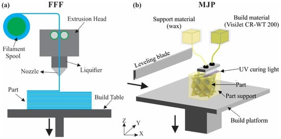
Figure 1.
Principals of (a) FFF and (b) MJP processes.
Generally, industries are seeking lightweight structures that are suitable for various applications, and one category that presents promising performance is the sandwich structures. A sandwich structure consists of a lightweight core that is embedded between two face sheets. It must be noted, that the structure of the core retains a critical factor concerning the bending as well as the buckling resistance of the whole structure. There are various types of sandwich structures, such as the foam core and the lattice core that can offer enhanced mechanical properties with minimum weight [12]. Extensive studies [13,14,15] have shown that sandwich structures with a lattice core presented remarkable mechanical responses. Moreover, along with the advances of AM technology, the fabrication and the testing of these structures is feasible as shown in various studies [16,17,18]. However, the existing literature needs further expansion with data on sandwich structures with 3D lattice core since the manufacturing techniques have been advanced in recent years. Thus, in the context of this work, sandwich structures with complex lattice patterns were investigated using AM technologies. More specifically, sandwich structures with sheet-TPMS lattice geometries, which possess unique properties such as low relative density, high stiffness coupled with low weight were manufactured utilizing two different AM methods, namely the FFF and MJP techniques.
The purpose of this study was to compare a sophisticated and industrialized AM process, namely the MJP, with an accessible and cost-effective AM procedure, i.e., the FFF, in order to examine the potential industrial use of FFF technologies in AM sandwich structures. ABS-like materials have been utilized in both techniques as the test material with a Schwarz diamond (SD) TPMS structure in different relative densities (i.e., 20%, 30%, and 40%). The dimensional accuracy, the surface finish as well as the mechanical behavior of the fabricated parts with different densities and AM technologies were compared. The main objective of the work is to investigate the effect of the relative density on the mechanical performance of these complex lattice structures using two different AM operations. The rest of the paper is organized as follows: Section 2 discusses the employed lattice structure, the details of the AM processes as well as the principal of the applied mechanical test. Section 3 outlines the experimental results and the finite element analysis of the test is presented. Finally, a short summary and conclusions of the study are drawn in Section 4.
2. Materials and Methods
2.1. Design of the Lattice Structures
There are a plethora of lattice structures that can be utilized for creating a sandwich structure. However, according to existing literature [19,20], TPMS have shown superior mechanical performance compared to other lattice structures. In addition, TPMSs offer additional advantages such as high porosity and large surface area to volume ratio, properties that are preferable in applications relevant to bioengineering, heat exchangers, catalysts [21,22,23,24]. TPMS structures are periodic geometries that extend in three dimensions and possess the unique topological characteristic of a mean curvature equal to zero at every point of their structure [25]. In order to design and produce TPMS structures, level-set approximation equations from a Fourier transformation are utilized extracting a three-dimensional trigonometric equation for each geometry in the form of f(x,y,z) = t, where ‘t’ is a level-set constant [26,27]. Employing the above-mentioned operation to produce a TPMS structure, it is feasible to build two different versions; the skeletal (walled) structure and the sheet structures as shown in Figure 2. In the context of this study, the sheet TPMS structures were investigated and more specifically the ones with the constant ‘t’ equal to zero, which offer the highest surface area to volume ratio and create two separate volumes granting a comprehensive advantage for potential applications such as in heat-exchange industry [28] and medical implants [29]. Existing research projects have studied many different sheet TPMS structures; but the most widespread structures are the Schwarz Primitive, the Gyroid, and the Schwarz Diamond. Each of these geometries is constructed by applying the trigonometry Equations (1)–(3), respectively. Figure 2 portrays the unit cells and a 2 × 2 × 2 configuration structure for each TPMS [20].
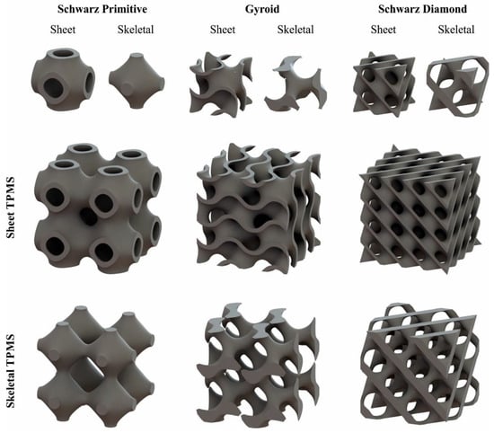
Figure 2.
Indicative 3D models of TPMS structures presenting one unit cell and a 2 × 2 × 2 configuration structure for Schwarz Primitive, Gyroid, and Schwarz Diamond.
Schwarz Primitive:
cosx + cosy + cosz = 0
Gyroid:
sinx cosy + siny cosz + sinz sinx = 0
Schwarz Diamond:
sinx siny sinz + sinx cosy cosz + cosx siny cosz + cosx cosy cosz = 0
According to literature, the Schwarz Diamond has shown the most advanced mechanical behavior among these three sheet TPMS lattice structures [17,30]. More specifically, SD structures exhibit an intense stretching-dominated behavior considering the Gibson and Ashby category of structures [31]. This behavior results in an almost linear relation between the relative density and the effective mechanical properties, in contrast to the exponential relations that other structures appear to present [32]. In addition, it is worth mentioning that the SD structure achieves a more uniform stress distribution inside its volume leading to remarkable mechanical strength properties [17]. Hereupon, the current work is focused on the investigation of the bending behavior of the SD structure in three different relative densities of 20%, 30%, and 40%. Figure 3 illustrates the digital 3D models that were used in the three-point bending tests.
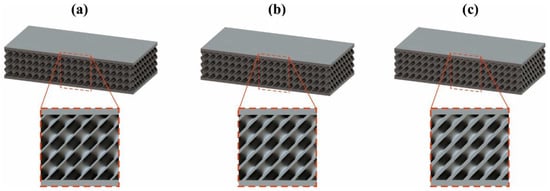
Figure 3.
3D models of SD TPMS structure for: (a) 20%, (b) 30% and (c) 40% relative density.
2.2. Additive Manufacturing Process
The specimens were manufactured via the Prusa i3 MK3S for the material extrusion process and through the ProJet MJP 5600 from 3D Systems for the material jetting procedure. The Prusa i3 MK3S 3D Printer utilizes the FFF 3D printing procedure providing a minimum layer height from 50 microns and a maximum build volume of 250 × 210 × 210 mm. The FFF printing process of the products was conducted without using material support. ProJet MJP 5600 offers the capability to simultaneously blend and print rigid with flexible photopolymers in order to achieve the desired mechanical performance. The maximum build volume is equal to 518 × 381 × 300 mm and the minimum layer height that the 3D printer can handle is 13 microns. In general, a sandwich structure consists of a core and two face sheets, where the material of the core could be different or even the same as the face sheets [33]. In the present study and due to the abilities of the AM technologies, both the core and the face sheets were created with the same material (ABS) in one single manufacturing process. In Figure 4, the applied AM methods are displayed in different stages of the manufacturing process and more specifically during and after the construction operation, where additional structures are also visible such as the brim in FFF and the prime blob structure in MJP that assure the smooth functioning of the corresponding printing process.
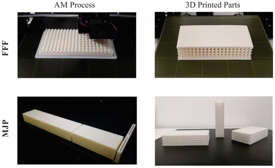
Figure 4.
The manufacturing procedures of FFF and MJP processes.
It must be noted that during the AM processes, the physical printed parts were constructed without structural defects such as layer debonding. Concerning the FFF process, the layer height was set equal to 300 μm, the applied print speed was 70 mm/s, the print temperature was equal to 260 °C and a 15% fan speed was used. Furthermore, a spring steel sheet with smooth double-sided PEI was utilized as a build platform at 100 °C using a 5 mm brim in order to achieve adhesion of the structures on the build platform. The layer height that is one of the few parameters that can be controlled in the MJP procedure had the lowest possible value equal to 13 μm. After the termination of the MJP operation, the specimens were post-processed in an oven in order to remove the support structures. The lattice structures were created using ABS filament for the material extrusion process and the VisiJet CR-WT 200 for the material jetting that is stated as an ABS-like material from the provider (3D Systems). The mechanical properties of the employed materials are presented in Table 1 for both of the AM procedures [34,35,36].

Table 1.
Mechanical properties of the employed material during the AM processes.
Furthermore, the dimensional accuracy and the surface quality were also evaluated for the manufactured specimens utilizing the digital microscope Leica DMS 1000 (Leica Microsystems GmbH, Wetzlar, Germany) and the software of MountainsLab® (Digital Surf, Besançon, France). The Leica DMS 1000 was equipped with a plan-apochromatic objective reaching magnification up to 300× capable of obtaining high-resolution images and extracting dimensional measurements. Moreover, the MountainsLab® software exploited these images and evaluated the surface quality through the calculation of various roughness parameters with an accuracy of ±1 μm.
2.3. Mechanical Testing Assisted by FEA
The bending behavior of the AM-produced sandwiches with a Schwarz diamond TPMS lattice structure in various core relative densities has been investigated according to ASTM C393 [37] using the universal testing machine Testometric-M500-50AT equipped with a 50 kN load cell. The components were placed considering the standards in order to compute their bending strength and bending modulus as well as their core shear ultimate strength and the facing stress. The dimensions of the produced parts for the three-point bending tests are documented in Table 2. The crosshead speed of the experiments was equal to 5 mm/min and the diameter of the supports and the punch was 10 mm. It is worth mentioning that all experiments were performed three times in order to secure the reliability and the repeatability of the experimental results.

Table 2.
Dimensional data of the produced sandwich structures.
An illustration of the employed experimental methodology for the three-point bending tests of the sandwich with a diamond TPMS lattice structure is illustrated in Figure 5. Specifically, in the left part of the figure, a cross-sectional view of the examined part is presented and the experimental setup along with the critical parameters of the test are exhibited on the right part. The bending modulus (Eb) and strength (σb) were calculated with the aid of the following equations:
where P is the applied load, S is the overall length of the support span, d is the thickness of the examined parts, b is equal to its width and m is the slope of the tangent to the initial straight line on the load-deflection curve [38]. Moreover, according to the ASTM C393 standard, the facing stress (σf) and the core shear ultimate strength (τcsu) were computed using Equations (6) and (7), correspondingly.
where c is the lattice core thickness in millimeters and t is the thickness of the face sheets.
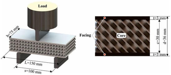
Figure 5.
Cross-section of the examined components and the principles of the three-point bending test.
In order to advance the calculation accuracy of the mechanical tests, a finite element analysis (FEA) model was developed. An explicit dynamics FEA based on the ANSYS code has been utilized to investigate the deformation process of 3D printed bending specimens and extract an elastoplastic constitutive model of their mechanical behavior. The material properties were based on the values of Table 1, regarding ABS and ABS-like structures. Different material parameters have been assumed in order to fit the experimental mechanical response of the specimens under bending, in terms of force–displacement. This procedure is repetitive until the last pair of force-depth values has converged and the solution process ends. The body interactions of the steel support, the punch, and the specimens’ surface were assumed to be frictionless. The FEA model employed a material erosion algorithm to study the failure and separation of the material. The 3D printing defects of each printing technology (FFF and MJP) have been neglected during the material erosion process. The material erosion technique removes distorted elements from the simulation, i.e., along the punch’s trajectory, based upon material failure and separation due to fracturing of its surface.
3. Results
3.1. Dimensional and Surface Finish Inspection
Despite the wide employment of AM technologies in several industries, the loss of geometric accuracy, as well as the potential presence of defects, hinder the broad adaption of these processes. In general, in an additively manufactured lattice structure, the geometric and dimensional accuracy could be influenced mainly by the staircase effect due to the layer-by-layer construction and by the overhang areas where they may decrease the underneath surface of the structure [39]. Furthermore, the randomly generated defects in the manufactured components may lead to inhomogeneity of the structure, which could cause the deterioration of its mechanical behavior. These factors arouse some second thoughts about the capabilities of AM technologies to build dimensional accurate lattice structures. In order to validate and inspect the constructed sandwiches with lattice structures, a non-destructive validation process was employed. More specifically, a visual-based inspection procedure like digital microscopy was utilized to examine several surface-related quality features such as shape deviations, cracks, and defects. Furthermore, the microscope was also applied in measuring the dimensional deviations of the produced complex geometrical features. Therefore, details about the 3D printed structures and their dimensional deviations with their corresponding CAD models are displayed in Figure 6. More specifically, Figure 6 illustrates two crucial dimensions of lattice structures that remain constant for specific relative density, namely the width of the pores (a) and the wall thickness (b). In the first row, the staircase effect, as well as the dimensional deviations, are noticeable with more than 500 μm for the width of pores and more than 100 μm for the wall thickness that led to a percentage deviation of close to 10%, restricting that way the utilization of FFF procedures in creating complex lattice structures. In contrast, the results for the Material Jetting Printing process are illustrated in the second row of the figure, where the integrity of the structure is highlighted, presenting negligible deviations compared to the corresponding digital files. More specifically, the percentage deviations of the examined dimensions were lower than 3% for the width of pores and lower than 6% for the wall thickness.
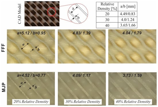
Figure 6.
Dimensional accuracy of the employed AM technologies in creating complex lattice structures.
Another aspect for evaluating the performance and the integrity of a manufactured part is its surface finish, where according to Lee et al. [40] surface quality could affect the mechanical behavior of a component. Surface finish is described as the characterization and the measurement of the surface topography, where the topography is mainly associated with the geometric data of the investigated surface [41]. The measurement of surface finish can increase our knowledge concerning the AM operation and potentially provide research directions for increasing the efficiency of the AM process itself. Surface finish characterization is associated with the data extraction from a surface in order to compute some critical parameters like the average roughness of an area (Sa), the root means square of the ordinate values (Sq), the mean roughness depth (Sz), the maximum pit height (Sv) and the maximum peak height (Sp) [42]. In Figure 7, the 2D false color maps of the generated top surfaces of the sandwich part are displaced for the FFF and MJP process on the first and second row correspondingly. Moreover, the computed parameters for evaluating the quality of the surface are presented also in Figure 7. It is evident from the experimental results, that the surface finish of the sandwich component manufactured via the MJP 5600 3D printer is superior compared to the one created using the FFF method. More specifically, MJP specimens achieved much lower values on the examined roughness parameters compared to the FFF ones. Indicatively, one of the most crucial indicators such as Sa, which demonstrates the difference in height of each point of the examined area compared to the arithmetical mean of the surface, was calculated fifteen times higher in the FFF compared to the MJP process. These results certified the superior performance of MJP procedures compared to FFF concerning the surface quality of the printed component. Furthermore, the attained values in both of the employed technologies are in good agreement with the literature [43,44]. Finally, it must be noted that the as-printed surface roughness of the part constructed using the MJP technology is satisfactory in many industrial applications; hence there is no need for post-process procedures to increase even further its surface characteristics.
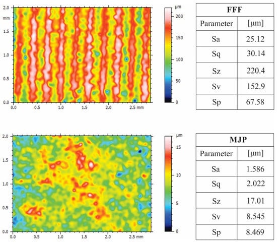
Figure 7.
Surface finish measurements of the constructed sandwich components.
3.2. Three-Point Bending Tests and FE Analyses
Three-point bending tests were conducted on the manufactured sandwich structures at relative densities equal to 20%, 30%, and 40% using two distinct AM techniques. The bending strength and bending modulus coupled with the force/displacement diagrams were extracted exploiting the abovementioned experiments. Figure 8 illustrates snapshots of the three-point bending experiments on various steps of the procedure both for the FFF and MJP AM processes. More specifically, each column represents a specimen with a specific relative density and each row shows the most significant stages of the experiment, namely at the beginning of the test, at the maximum force, and at the failure of the TPMS structure.
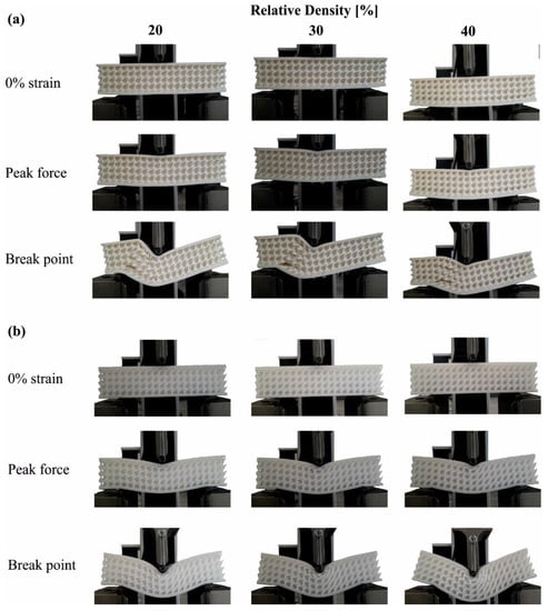
Figure 8.
Sandwich components under three-point bending test in (a) FFF and (b) MJP.
In Figure 8a, the specimens that were manufactured with the FFF technology are portrayed. Regardless of the applied relative density of each specimen, a specific pattern was observed on all the FFF samples. This pattern was initiated simultaneously along with the loading and showed a stress concentration on the region of the applied force. Furthermore, the upper face sheet and the unit cells below the contact probe were compressed and distributed the loads on the specimen’s structure. The edges of the specimens received the reaction forces through the supports. The combination of these loads resulted in extensive development of shear stresses inside the structure of the sandwich coupled with a tensile stress concentration at the bottom face sheet perpendicular to the applied force. The main fracture of the specimens occurred when the intense shear stresses evoked the detachment of the structure’s layers and the breakage of the specimen’s structure was emerging, which is visible in the last row of Figure 8a. It is worth mentioning that intense shear stresses were developed symmetrically to the punch, however, the delamination occurred to the right side of specimens, possibly due to the concentration of micro-defects in the internal structure of the parts produced from the AM processes. Moreover, a secondary fracture occurred when the bottom facing failed due to the high concentration of tensile stresses.
Figure 8b illustrates the three-point bending tests for all specimens that were fabricated utilizing the MJP process. A different pattern concerning the fracture of the structure was observed in this technology compared to the FFF one. This difference is based on the mechanical behavior of the construction material. More specifically, the ABS-like VisiJet CR-WT 200 material appeared to be more ductile than the ABS filament. This led to the development of a high bending strain regardless of the relative density of the specimens. In the second row of Figure 8b, the ductile nature of the material was apparent during the loading stage because the unit cells and the upper face sheet were locally compressed and received high strains without distributing the loads in the rest of the structure. As a result, the overall structure of the MJP specimens was mainly intact presenting single points of failure. The fracture of the specimens occurred when the unit cells close to the punch were severely deformed and spots of the structure were separated.
The experimental data of the three-point bending tests are presented in Figure 9 where the force versus the displacement for the manufactured structures using FFF (Figure 9a) and MJP (Figure 9b) are portrayed, respectively. Figure 9a displays the mechanical behavior of FFF sandwich specimens under three-point bending loading in three different core’s relative densities. The diagrams show a rigid behavior with the limited elastic region, peak strength point, fracture, and instant drop of the load afterward in a relatively small deformation. The bending strength and stiffness of each specimen are directly influenced by the core’s relative density. More specifically, at core’s relative density equal to 40%, 30% and 20% the ultimate bending forces reached up to 15,481 N, 9438 N, and 6004 N, respectively. The flexural stiffness, defined as the ratio of force to deformation in the elastic region, is a criterion of measuring deformability and followed the same trend with the ultimate bending forces, measured at 2792 N/mm, 3381 N/mm MPa, and 4576 N/mm for relative densities of 20%, 30% and 40% correspondingly.
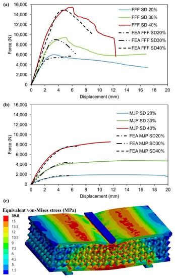
Figure 9.
Experimental load–displacement response for Schwarz diamond structures in (a) FFF, (b) MJP curve-fitted by FEA generated data and (c) Stress distribution on a typical sandwich SD structure under bending load, utilizing the ABS material properties in the FE model.
Figure 9b displays the mechanical response of the MJP sandwich structures during the three-point bending tests in the three examined relative densities. In contrast with the FFF specimens, a more ductile behavior was observed with the appearance of a plateau region beyond the linear region, reaching remarkable plasticity and deformation. This ductile performance led to a reduction of the bending modulus in MJP specimens, namely the values of the flexural stiffness were measured at 945 N/mm, 1793 N/mm, and 2680 N/mm for 20%, 30%, and 40% relative density, respectively. The ultimate bending forces of these MJP specimens were also influenced by the ductile response of the structures decreasing the maximum peak force compared to the FFF bending specimens. More specifically, the peak forces for the MJP specimens were equal to 1944 N, 4780 N, and 8654 N for relative densities of 20%, 30%, and 40% correspondingly. It is must be noted that both in FFF and MJP specimens, as the relative density increases, the elongation at the peak force also grows resulting in high deformation of the specimens.
In addition, a computational model was also employed in order to evaluate the stress response of the 3D printed specimens under bending. This model was developed using the finite element software ANSYS™. Meshing was generated using tetrahedral elements for complex geometries. In order to ensure the mesh-independent response, a convergence study was performed. Based on the convergence results performed for the elastoplastic response of the lattice structures, an average element size of 1 mm was considered to be adequate to obtain acceptable accuracy in the calculated responses. In Figure 9a,b the finite element analysis (FEA) results of force-displacement behavior are demonstrated, revealing a good correlation between the experimental compression tests and the force-displacement data generated by FEA simulations, for both FFF and MJP 3D printed specimens. It is worth mentioning that at larger displacements, the experimental curves start to deviate more from the FEA simulation because the 3D printing defects play a larger role in the bending response. The material model parameters were examined to minimize the difference between the simulated and the experimental force-displacement data. Therefore, the results of the equivalent von Mises stress distribution on the 3D printed sandwich SD lattice structures under bending load, as shown in Figure 9c, may accurately indicate the high-stress regions of the structures. Based on the mechanical test results it can be established that the computationally generated (FEA) compression test data, assisted by the actual measurements could be an effective method to characterize the mechanical deformation behavior of 3D printed bending specimens.
Figure 10 shows the experimental results concerning the bending strength and modulus, as well as the ultimate core’s shear strength and the peak facing stresses in order to elucidate the behavior of the sandwich lattice structures. It is evident, that the surface roughness of a part is associated mainly with its fatigue endurance stress [40]. More specifically, the lower the quality in surface finish, the higher is the possibility for lower fatigue life and crack initiation. However, in the present study, the mechanical properties of the ABS thermoplastic in the FFF process are superior compared to the ABS-like thermoset polymer applied in the MJP procedure. Hence, the bending behavior of the printed components using the FFF technology is better even though its surface roughness is restricted. In particular, regarding the FFF printed bending specimens, at core’s relative density equal to 40%, 30%, and 20% the bending strengths reached up to 24.69 MPa, 13.89 MPa, and 9.26 MPa respectively. The bending modulus followed the same trend with the bending strength, measured at 178.61 MPa, 226.24 MPa, and 324.5 MPa for relative densities of 20%, 30%, and 40%, correspondingly. The abovementioned values lead to the induction that both bending strength and modulus follow an exponential relation regarding the applied relative density of the lattice structure. According to the literature [19,31,32], the majority of the mechanical properties of lattice structures follow an exponential trend, namely the scaling laws, and the bending properties are satisfied by similar behavior. It must be noted, that FFF and MJP are two different AM procedures based on distinct working principles and types of materials like thermoplastics and thermoset polymers correspondingly. Nevertheless, the comparison of their performance is valuable in order to extract useful data and information about their potential in applying these technologies for constructing industrial-wise AM sandwich structures.
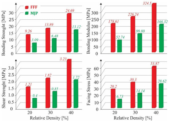
Figure 10.
Experimental results for the bending strength, bending modulus, shear strength, and facing the stress of the investigated TPMS structure in various relative densities.
Regarding MJP printed bending specimens, the peak strength was equal to 3.09 MPa, 6.48 MPa, and 13.12 MPa for relative densities of 20%, 30%, and 40% correspondingly, while the bending modulus was measured at 52.74 MPa for the 20% relative density, 99.8 MPa and 166.32 MPa for 30% and 40% relative density respectively. It is worth mentioning that the bending properties of MJP specimens also follow an exponential behavior versus the applied relative density. However, the exponential relations were more intense compared to the FFF specimens due to the more ductile nature of the feedstock material. The bending and shear stresses were responsible for the component’s fractures and resulted in the detachment of the material structure and the fracture of the facings. It must be noted that for the FFF parts, higher stresses both in core (shear stresses) and in facings were observed compared to the MJP specimens. The shear stresses for the densities of 20%, 30%, and 40% of the FFF specimens reached up to 1.21, 1.82, and 3.23 MPa and 0.40, 0.85, and 1.72 MPa for the MJP structures respectively. The corresponding values for the peak facing stresses were computed equal to 20.20, 30.30, and 53.87 MPa for FFF and 6.73, 14.14, and 28.62 MPa for the MJP specimens. It is worth mentioning that these two mechanical quantities were influenced by the applied relative density in an identical manner. More specifically, both mechanical properties follow an exponential trend versus the relative density and present almost similar increment/decrement rates. This phenomenon was observed on all specimens regardless of the applied AM technology; however, the rates of these properties are not constant for each manufacturing process.
4. Conclusions
The present study investigated the bending mechanical behavior of sandwich structures constructed with the Schwarz diamond TPMS lattice structure as core and thin sheets of the same material as facings manufactured with two different AM methods, the MPJ and FFF processes. The understanding of the mechanical behavior of these structures composes an essential step in order to consider potential commercial applications utilizing TPMS lattice structures. Due to the high load-carrying capacity and the light weight, AM lattice structures could potentially be employed in aircraft and aerospace industries as well as for creating structural efficient lightweight medical implants. Furthermore, as the relative density possesses the most dominant effect in the mechanical performance of sandwich structures with a lattice core, it is feasible to develop models predicting their mechanical response, facilitating that way their adaptation in various industries. Therefore, in the present paper, the bending mechanical behavior of the structures was evaluated utilizing three-point bending experiments and finite element analysis applied in three distinct core’s relative densities. Furthermore, a quality inspection of the 3D printed structures was performed in terms of dimensional accuracy and surface roughness. The MJP specimens showed the highest quality in terms of dimensional accuracy and surface roughness. However, the FFF specimens presented superior strength and bending modulus compared to MJP specimens, reaching up to 24.69 MPa and 324.51 MPa for 40% specimen’s relative density respectively. It must be noted that the enhanced mechanical performance of the FFF components is due to the superior mechanical properties of the feedstock material. Furthermore, an intense ductile behavior was observed on MJP specimens with high strains indicating enhanced energy absorption rates and potentially high crashworthiness. These results are associated exclusively with the applied AM process and the construction material. Moreover, all the bending-related mechanical properties, namely the bending modulus, the bending strength, the ultimate core’s shear stress, and the facing stresses were governed by exponential relations depending on the applied relative density regardless of the employed AM technology. Finally, it is worth mentioning that the relative density influenced the ultimate core’s shear stress and the facing stresses in a similar manner.
Author Contributions
Conceptualization, N.K., P.C., K.T. and I.K.; methodology, N.K., P.C. and K.T.; software, N.K., P.C., K.T.; formal analysis, N.K., P.C. and I.K.; investigation, N.K., P.C. and I.K.; resources, N.K.; data curation, N.K., P.C. and K.T.; writing—original draft preparation, N.K., P.C.; writing—review and editing, I.K., D.T. (Dimitrios Tzetzis) and D.T. (Dimitrios Tzovaras); supervision, I.K., D.T. (Dimitrios Tzetzis) and D.T. (Dimitrios Tzovaras); project administration, D.T. (Dimitrios Tzetzis) and D.T. (Dimitrios Tzovaras). All authors have read and agreed to the published version of the manuscript.
Funding
This research received no external funding.
Acknowledgments
We acknowledge the support of this work by the project “Intelligent και Automated Systems for enabling the Design, Simulation, and Development of Integrated Processes and Products—ODYSSEAS” (MIS 5002462) which is implemented under the “Action for the Strategic Development on the Research and Technological Sector”, funded by the Operational Programme “Competitiveness, Entrepreneurship and Innovation” (NSRF 2014–2020) and co-financed by Greece and the European Union (European Regional Development Fund).
Conflicts of Interest
The authors declare no conflict of interest.
References
- Khosravani, M.R.; Zolfagharian, A.; Jennings, M.; Reinicke, T. Structural performance of 3D-printed composites under various loads and environmental conditions. Polym. Test. 2020, 91, 106770. [Google Scholar] [CrossRef]
- Gibson, I.; Rosen, D.W.; Stucker, B. Additive Manufacturing Technologies, 1st ed.; Springer: New York, NY, USA, 2010. [Google Scholar] [CrossRef]
- Kladovasilakis, N.; Charalampous, P.; Kostavelis, I.; Tzetzis, D.; Tzovaras, D. Impact of metal additive manufacturing parameters on the powder bed fusion and direct energy deposition processes: A comprehensive review. Prog. Addit. Manuf. 2021, 6, 349–365. [Google Scholar] [CrossRef]
- Charalampous, P.; Kostavelis, I.; Tzovaras, D. Non-destructive quality control methods in additive manufacturing: A survey. Rapid Prototyp. J. 2020, 26, 777–790. [Google Scholar] [CrossRef]
- Fudos, I.; Ntousia, M.; Stamati, V.; Charalampous, P.; Kontodina, T.; Kostavelis, I.; Tzovaras, D.; Billalis, L. A characterization of 3D Printability. Comput.-Aided Des. Appl. 2021, 18, 1279–1295. [Google Scholar] [CrossRef]
- Kladovasilakis, N.; Kontodina, T.; Charalampous, P.; Kostavelis, I.; Tzetzis, D.; Tzovaras, D. A case study on 3D scanning, digital reparation and rapid metal additive manufacturing of a centrifugal impeller. In Proceedings of the 24th Innovative Manufacturing Engineering and Energy International Conference (IManEE), Athens, Greece, 14–15 December 2020; Volume 1037, p. 012018. [Google Scholar] [CrossRef]
- ASTM F2792-12a. Standard Terminology for Additive Manufacturing Technologies (Withdrawn, 2015); ASTM International: West Conshohocken, PA, USA, 2012. [Google Scholar] [CrossRef]
- Mazzanti, V.; Malagutti, L.; Mollica, F. FDM 3D Printing of Polymers Containing Natural Fillers: A Review of their Mechanical Properties. Polymers 2019, 11, 1094. [Google Scholar] [CrossRef] [PubMed] [Green Version]
- Charalampous, P.; Kostavelis, I.; Kontodina, T.; Tzovaras, D. Learning-based error modeling in FDM 3D printing process. Rapid Prototyp. J. 2021, 27, 507–517. [Google Scholar] [CrossRef]
- Vassilakos, A.; Giannatsis, J.; Dedoussis, V. Fabrication of parts with heterogeneous structure using material extrusion additive manufacturing. Virtual Phys. Prototyp. 2021, 16, 267–290. [Google Scholar] [CrossRef]
- Cheng, Y.-L.; Huang, K.-C. Preparation and Characterization of Color Photocurable Resins for Full-Color Material Jetting Additive Manufacturing. Polymers 2020, 12, 650. [Google Scholar] [CrossRef] [Green Version]
- Feng, Y.; Qiu, H.; Gao, Y.; Zheng, H.; Tan, J. Creative design for sandwich structures: A review. Int. J. Adv. Robot. Syst. 2020, 17. [Google Scholar] [CrossRef]
- Dong, L.; Deshpande, V.; Wadley, H. Mechanical response of Ti–6Al–4V octet-truss lattice structures. Int. J. Solids Struct. 2015, 60–61, 107–124. [Google Scholar] [CrossRef]
- Ullah, I.; Brandt, M.; Feih, S. Failure and energy absorption characteristics of advanced 3D truss core structures. Mater. Des. 2016, 92, 937–948. [Google Scholar] [CrossRef]
- Gautam, R.; Idapalapati, S.; Feih, S. Printing and characterization of Kagome lattice structures by fused deposition modeling. Mater. Des. 2018, 137, 266–275. [Google Scholar] [CrossRef]
- Xiao, D.; Chen, X.; Li, Y.; Wu, W.; Fang, D. The structure response of sandwich with metallic auxetic honeycomb corers under localized impulsive loading experiments and finite element analysis. Mater. Des. 2019, 176, 107840. [Google Scholar] [CrossRef]
- Kladovasilakis, N.; Tsongas, K.; Tzetzis, D. Mechanical and FEA-Assisted Characterization of Fused Filament Fabricated Triply Periodic Minimal Surface Structures. J. Compos. Sci. 2021, 5, 58. [Google Scholar] [CrossRef]
- Hou, S.; Li, T.; Jia, Z.; Wang, L. Mechanical properties of sandwich composites with 3D-printed auxetic and non-auxetic lattice cores under low velocity impact. Mater. Des. 2018, 160, 1305–1321. [Google Scholar] [CrossRef]
- Al-Ketan, O.; Rowshan, R.; Abu Al-Rub, R.K. Topology-mechanical property relationship of 3D printed strut, skeletal, and sheet based periodic metallic cellular materials. Addit. Manuf. 2018, 19, 167–183. [Google Scholar] [CrossRef]
- Zheng, X.; Fu, Z.; Du, K.; Wang, C.; Yi, Y. Minimal surface designs for porous materials: From microstructures to mechanical properties. J. Mater. Sci. 2018, 53, 10194–10208. [Google Scholar] [CrossRef]
- Al-Ketan, O.; Rezgui, R.; Rowshan, R.; Du, H.; Fang, N.X.; Abu Al-Rub, R.K. Microarchitected Stretching-Dominated Mechanical Metamaterials with Minimal Surface Topologies. Adv. Eng. Mater. 2018, 20, 1800029. [Google Scholar] [CrossRef]
- Kladovasilakis, N.; Tsongas, K.; Tzetzis, D. Finite Element Analysis of Orthopedic Hip Implant with Functionally Graded Bioinspired Lattice Structures. Biomimetics 2020, 5, 44. [Google Scholar] [CrossRef]
- Pelanconi, M.; Ortona, A. Nature-Inspired, Ultra-Lightweight Structures with Gyroid Cores Produced by Additive Manufacturing and Reinforced by Unidirectional Carbon Fiber Ribs. Materials 2019, 12, 4134. [Google Scholar] [CrossRef] [Green Version]
- Hurt, C.; Brandt, M.; Priya, S.S.; Bhatelia, T.; Patel, J.; Selvakannan, P.; Bhargava, S. Combining additive manufacturing and catalysis: A review. Catal. Sci. Technol. 2017, 7, 3421–3439. [Google Scholar] [CrossRef]
- Do Carmo, M.P. Differential Geometry of Curves and Surfaces: Revised and Updated, 2nd ed.; Courier Dover Publications: Mineola, NY, USA, 2016. [Google Scholar]
- Al-Ketan, O.; Abu Al-Rub, R.K. Multifunctional Mechanical Metamaterials Based on Triply Periodic Minimal Surface Lattices: A review. Adv. Eng. Mater. 2019, 21, 1900524. [Google Scholar] [CrossRef]
- Qu, S.; Ding, J.; Song, X. Achieving Triply Periodic Minimal Surface Thin-Walled Structures by Micro Laser Powder Bed Fusion Process. Micromachines 2021, 12, 705. [Google Scholar] [CrossRef]
- Boomsma, K.; Poulikakos, D.; Zwick, F. Metal foams as compact high performance heat exchangers. Mech. Mater. 2003, 35, 1161–1176. [Google Scholar] [CrossRef]
- Wang, P.; Li, X.; Luo, S.; Nai, M.; Ding, J.; Wei, J. Additively manufactured heterogeneously porous metallic bone with biostructural functions and bone-like mechanical properties. J. Mater. Sci. Technol. 2021, 62, 173–179. [Google Scholar] [CrossRef]
- Sychov, M.; Lebedev, L.; Dyachenko, S.; Nefedova, L. Mechanical properties of energy-absorbing structures with triply periodic minimal surface topology. Acta Astronaut. 2018, 150, 81–84. [Google Scholar] [CrossRef]
- Gibson, L.J.; Ashby, M.F. Cellular Solids: Structure & Properties; Pergamon Press: Oxford, UK, 1988; ISBN 0-08-036607-4. [Google Scholar] [CrossRef]
- Wang, P.; Li, X.; Jiang, Y.; Nai, M.; Ding, J.; Wei, J. Electron beam melted heterogeneously porous microlattices for metallic bone applications: Design and investigations of boundary and edge effects. Addit. Manuf. 2020, 36, 101566. [Google Scholar] [CrossRef]
- Zaharia, S.M.; Enescu, L.A.; Pop, M.A. Mechanical Performances of Lightweight Sandwich Structures Produced by Material Extrusion-Based Additive Manufacturing. Polymers 2020, 12, 1740. [Google Scholar] [CrossRef] [PubMed]
- 3D Systems. Available online: https://www.3dsystems.com/ (accessed on 10 May 2021).
- Wu, W.; Geng, P.; Li, G.; Zhao, D.; Zhang, H.; Zhao, J. Influence of Layer Thickness and Raster Angle on the Mechanical Properties of 3D-Printed PEEK and a Comparative Mechanical Study between PEEK and ABS. Materials 2015, 8, 5834–5846. [Google Scholar] [CrossRef]
- Saroha, V.; Pabla, B.S.; Bhogal, S.S. Characterization of ABS for Enhancement of Mechanical Properties. Int. J. Innov. Technol. Explor. Eng. 2019, 8. [Google Scholar] [CrossRef]
- ASTM C393/C393M-20. Standard Test Method for Core Shear Properties of Sandwich Constructions by Beam Flexure; ASTM International: West Conshohocken, PA, USA, 2020. [Google Scholar] [CrossRef]
- Zaharia, S.M.; Pop, M.A.; Udroiu, R. Reliability and Lifetime Assessment of Glider Wing’s Composite Spar through Accelerated Fatigue Life Testing. Materials 2020, 13, 2310. [Google Scholar] [CrossRef] [PubMed]
- Meng, L.; Qiu, X.; Gao, T.; Li, Z.; Zhang, W. An inverse approach to the accurate modelling of 3D-printed sandwich panels with lattice core using beams of variable cross-section. Compos. Struct. 2020, 247, 112363. [Google Scholar] [CrossRef]
- Lee, J.; Nagalingam, A.; Yeo, S. A review on the state-of-the-art of surface finishing processes and related ISO/ASTM standards for metal additive manufactured components. Virtual Phys. Prototyp. 2021, 16, 68–96. [Google Scholar] [CrossRef]
- Townsend, A.; Senin, N.; Blunt, L.; Leach, R.K.; Taylor, J.S. Surface texture metrology for metal additive manufacturing: A review. Precis. Eng. 2016, 46, 34–47. [Google Scholar] [CrossRef] [Green Version]
- Whip, B.; Sheridan, L.; Gockel, J. The effect of primary processing parameters on surface roughness in laser powder bed additive manufacturing. Int. J. Adv. Manuf. Technol. 2019, 103, 4411–4422. [Google Scholar] [CrossRef]
- Barrios, J.M.; Romero, P.E. Improvement of Surface Roughness and Hydrophobicity in PETG Parts Manufactured via Fused Deposition Modeling (FDM): An Application in 3D Printed Self–Cleaning Parts. Materials 2019, 12, 2499. [Google Scholar] [CrossRef] [Green Version]
- Cheng, Y.-L.; Chang, C.-H.; Kuo, C. Experimental study on leveling mechanism for material-jetting-type color 3D printing. Rapid Prototyp. J. 2020, 26, 11–20. [Google Scholar] [CrossRef]
Publisher’s Note: MDPI stays neutral with regard to jurisdictional claims in published maps and institutional affiliations. |
© 2021 by the authors. Licensee MDPI, Basel, Switzerland. This article is an open access article distributed under the terms and conditions of the Creative Commons Attribution (CC BY) license (https://creativecommons.org/licenses/by/4.0/).