Article

High-Precision Adjustment of Welding Depth during Laser Micro Welding of Copper Using Superpositioned Spatial and Temporal Power Modulation

1
Chair for Laser Technology LLT, RWTH Aachen University, Steinbachstraße 15, 52074 Aachen, Germany
2
Fraunhofer-Institute for Laser Technology ILT, Steinbachstraße 15, 52074 Aachen, Germany
*
Author to whom correspondence should be addressed.
J. Manuf. Mater. Process. 2021, 5(4), 127; https://doi.org/10.3390/jmmp5040127
Submission received: 5 November 2021 / Revised: 19 November 2021 / Accepted: 23 November 2021 / Published: 25 November 2021
(This article belongs to the Special Issue Advanced Joining Processes and Techniques)

Abstract

:
For joining metallic materials for battery applications such as copper and stainless steel, laser beam micro welding with beam sources in the near-infrared range has become established in recent years. In laser beam micro welding, spatial power modulation describes the superposition of the linear feed motion with an oscillating motion. This modulation method serves to widen the cross-section of the weld seam as well as to increase the process stability. Temporal power modulation refers to the controlled modulation of the laser power over time during the welding process. In this paper, the superposition of both temporal and spatial power modulation methods is presented, which enables a variable control of the weld penetration depth. Three weld geometries transverse to the feed direction are part of this investigation: the compensation of the weld penetration depth due to the asymmetric path movement during spatial power modulation only, a W-shaped weld profile, and a V-shaped. The weld geometries are investigated by the bed on plate weld tests with CuSn6. Furthermore, the use of combined power modulation for welding tests in butt joint configuration between CuSn6 and stainless steel 1.4301 with different material properties is investigated. The study shows the possibility of precise control of the welding depth by this methodology. Depending on the material combination, the desired regions with maximum and minimum welding depth can be achieved by the control of local and temporal power modulation on the material surface.

1. Introduction

Energy storage systems are gaining importance due to the increasing trend of electrification, especially the stationary application as intermediate storage for power generation from renewable energies and electromobility devices. In the production of high-performance battery packs, lithium-ion cells are used due to their high energy density and good weldability of the stainless steel casing [1,2]. To establish electrical contact between the cells, electrically conductive bonds are connected to the cells. Copper bonds are suitable for cell contacting due to their high electrical and thermal conductivity but cannot be processed in conventional ultrasonic joining due to their high thermal conductivity [3]. Laser beam micro welding offers a highly automatable, contactless joining method whereby copper bonds can be processed. Compared to conventional welding processes, the intensity of the energy input is increased by focusing the laser beam down to several 10 µm in diameter to precisely weld materials with high thermal conductivity [4]. To protect the sensitive joining partners, a defined weld geometry is crucial in order not to damage the cell and at the same time to guarantee a large cross-section for the electrical current flow [5]. The weld geometry, defined by width and depth, must not deviate from the defined values due to fluctuations and process influences. If the weld seams are too wide, adjacent components on the surface, such as seals or electronic components, may be damaged. In the event of fluctuations or deviations in the welding depth, underlying material such as polymer substrates or electrolytes in battery storage systems can be destroyed.
In laser micro welding, spatial power modulation (PM) describes the superposition of the linear feed motion with an oscillating motion. This makes the one-dimensional movement of conventional laser beam micro welding two-dimensional and allows both processing wider weld seams as well as a more stable process without pore or crack formation [6,7,8,9]. Additional parameters in the welding process, such as oscillation amplitude, allow further degrees of freedom in the design of the weld seam width [10,11]. This adjusted weld seam width is mainly influenced by the movement of the scanning system, which is highly reliable and not affected by any process errors. One negative effect of this oscillation shape is the asymmetry of the path velocity of the laser beam. Differences in velocity have an effect on the energy per unit length and thus the weld penetration depth [12,13,14].
The combination of spatial and temporal power modulation offers new possibilities to control the difference of the energy input by means of adapted laser power during the process [5,15,16]. A combination of spatial and temporal power modulation for processing aluminum and copper was demonstrated by Kraetzsch et al. with a 1D scanning system. They adjusted the laser power along with the linear movement of the laser beam. By adjusting the laser power and thus the heat input into the material, they could control the formation of intermetallic phases and thus reduce the formation of cracks and increase the tensile strength of the joining area [17]. The combination of both methods for a 2D circular movement of the laser beam is shown by Chen et al. in welding dissimilar materials of aluminum AA6061 and titanium Ti6Al4V in butt joint configuration for a macroscopic attempt with a laser beam diameter of 460 µm. By lowering the laser power on the titanium alloy material, they could compensate the penetration depth transverse to the feed direction. [18] However, this method has not yet been adapted to microscopic welds of copper and stainless steel material and shows new possibilities to freely design the cross-section geometry of the weld seams.
The aim of this work is to investigate the feasibility of influencing the weld geometry during laser beam micro welding by means of combining spatial and temporal power modulation. The compensation of the welding depth difference due to the spatial modulation is investigated. Furthermore, the possibilities of welding other weld geometries (W-shaped and V-shaped profile) and the welding of materials in butt joint configuration with different degrees of absorption and thermal conductivity (1.4301 stell and CuSn6 copper) of the joining partners are investigated. To analyze the measures taken for the modulation method, the energy coupling during the process is additionally measured with two integrating spheres and photo diodes.
To conduct the study, an experimental setup is first created that allows the synchronization of the moving laser beam and the modulation of the laser power. Then, a study is carried out in which the phase shift between local and temporal modulation is varied. This is used to investigate at which difference of the two signals the optimal result of the defined weld penetration geometries can be achieved. The investigations are carried out with constant laser parameters.

2. Materials and Methods

2.1. Theoretical Principles

In heat conduction welding, the material is heated locally to a temperature above the melting point, whereby the energy coupling into the material takes place exclusively at the material surface. Due to reflection levels > 95% of copper in the infrared range, only a relatively small proportion of the energy is introduced into the material [19]. The energy transport from the surface into the material only takes place through heat conduction. By increasing the power density of the radiation, the transition from heat conduction welding to deep penetration welding can be realized (Figure 1).
Reaching the intensity threshold, the vaporization temperature of the material is exceeded, and the material becomes gaseous. The outflowing metal vapor depresses the surface and a vapor channel, called a vapor capillary develops inside the material. By this circumstance, the laser radiation is channeled deeper into the material and increases the total energy absorption (energy coupling). This creates very deep and narrow weld seams with a very high aspect ratio a = depth/width up to a value of 15 [21].
With local power modulation, the linear feed motion is superimposed with an independent oscillating motion, and thus, the laser motion is two-dimensional [9]. Figure 2 shows a schematic representation of local power modulation. By means of the local modulation, the aspect ratio is reduced while the welding depth remains the same. This makes it possible to widen the narrow weld seams and to improve the mechanical, thermal, and electrical properties of the welded connection. [13,22] As a result, local modulation has become more important, especially for joining copper and aluminum.
Oscillatory motion is generated by the superposition of two periodic, orthogonal motions. Possible oscillating movements are linear (one-dimensional movement transverse to the feed direction), circular, elliptical, and octagonal. The use of circular oscillation has gained acceptance in laser beam micro welding because experiments have shown that molten pool ejections are reduced compared to other forms of oscillation and conventional welding [22,23,24].
The spiral trajectory of the laser beam using a circular oscillation movement is described by Equation (1)
x t y t = v f t + A s c o s 2 π f s t t s A s s i n 2 π f s t t s
where v f is the feed rate, f s the oscillation frequency A s the oscillation amplitude, and t / t s the time [19]. The oscillation amplitude corresponds to the radius of the circular motion.
A detrimental effect caused by the superposition of a circular oscillation with the linear feed motion in local power modulation is the asymmetry of the path motion of the laser. The formal relationship of this absolute velocity v P a t h t is described in Equation (2). The absolute speed is highest in the direction of the linear feed rate and lowest in the opposite direction.
v P a t h t = v f 2 π f s A ö s i n 2 π f s t t s 2 + 2 π f s A s c o s 2 π f s t t s 2
After calculating the magnitude of the path velocity, the result is a sinusoidal course. Since the energy per unit length E p a t h t , the energy on the material per unit length, is directly proportional to the path velocity, it also changes in the course of an oscillation. Equation (3) describes this relationship mathematically with
E p a t h t = P L | v P a t h t |
where P L describes the laser power and v P a t h t the path velocity on the material surface. The energy per unit length influences the shape and depth of the molten pool and the vapor capillary, which causes the weld penetration depth to be greater at points with high energy per unit length than at low energy per unit length. This results in tilted weld seams transverse to the feed direction. [15,25].

2.2. Experimental Plan and Setup

For all experiments within the scope of this work, a fiber laser of the type SPI400C from the company SPI Lasers (Southampton, UK) is used as the beam source. The laser emits radiation with a wavelength of λ = 1064 nm, the beam quality is M2 < 1.1, and the maximum measured power output PL,max = 423 W. The feed motion and the oscillation motion of the local power modulation are generated by a galvanometer scanner of the model intelliSCAN20 (Scanlab) by means of two rotatable mirrors. The output laser beam from the scanner system is focused by f-theta optics from Sill Optics with a focal length of f = 163 mm. The laser beam is focused to a focal diameter of 38 µm for sufficient laser beam intensity.
In the case of temporal power modulation with a laser beam source, one possibility for the power variation is achieved by superimposing the constant power P L ,   m e d with a periodic power modulation. Thus, the laser power results in
P L , S i n u s t = P L ,   m e d + A t s i n 2 π f t t t t .
where P L , m e d is the constant laser power, A t the laser power amplitude and f t the frequency of the laser power modulation and t / t t the time.
The weld-in profile of laser beam micro welding without modulation is narrow with a high aspect ratio. The weld seam of a weld with local power modulation with a circular oscillation is wider and shows an oblique seam bottom in the transverse section. In the feed direction with a clockwise circular oscillation movement, the weld has the minimum weld penetration depth on the left side and the maximum weld penetration depth on the opposite side. Figure 3 shows a schematic diagram of the weld-in geometries that are tried to be achieved in this work.
By combining local and temporal power modulation, the influence on the weld geometry is investigated by means of bed on plate welding tests for three weld penetration profiles: the compensation of the weld penetration depth difference due to local power modulation, a W-shaped weld penetration profile with the minimum weld penetration depth between two maximum depths, and a V-shaped profile with the maximum depth between two minimum depths.
To investigate the influence of local and temporal power modulation on the weld geometry during the transition between metals with different material properties, welding tests are carried out in butt joint configuration. Figure 4 shows the schematic representation of two weld-in profiles of welds in the butt joint.
The aim of the investigation is to demonstrate the possibility of compensating for the difference in weld penetration depth due to the different material properties. The different material properties are listed in Table 1.
For compensation for the difference in weld penetration depth due to the local power modulation, the amplitude of the temporal power modulation must be varied by the same factor as the change in velocity.
The study is carried out by changing the phase shift between local and temporal modulation (see Figure 5). This is used to investigate at which difference of the two signals the optimal result of the defined weld penetration geometries can be achieved. The investigations are carried out with constant laser parameters such as feed rate and laser power to ensure comparability of the results. An average laser power of 360 W and a feed rate of 75 mm/s was used in order to use both process-technically sensible and frequently used feed rates as well as to obtain a continuous deep welding process without collapse of the process. The selected parameters for the investigation are shown in Table 2.
The temporal power modulation is adjusted by ±40 W for the bed on plate welds on CuSn6 to compensate for the change in path velocity. For the joining of the dissimilar material combination, the temporal power modulation was increased up to ±60 W to additionally compensate for the difference in the material properties between CuSn6 and 1.4301. This was the highest amplitude possible with the used laser beam source. To take into account statistical fluctuations in the process, all tests were carried out with a number of n = 3 in order to exclude outliers in the results.
Decisive for the formation of the weld-in profiles is the position of the maximum and minimum laser power due to the temporal modulation on the oscillation loop. Figure 5 shows the schematic representation of the laser power depending on the position of the laser beam.
While the compensation of the difference in welding depth is investigated with the same frequency of the local and the temporal power modulation, the welding tests for the generation of the W-profile and the V-profile are carried out with a frequency of the temporal power modulation twice as high as the frequency of the spatial one. As a result, the minimum and maximum of the energy per unit length alternate every 90° on the track of the spatial power modulation.
Table 3 lists the areas on the oscillation curve where the maximum and minimum laser power was positioned. Between these limits, the phase of the laser power was varied in ∆φ = 5° steps for investigation.

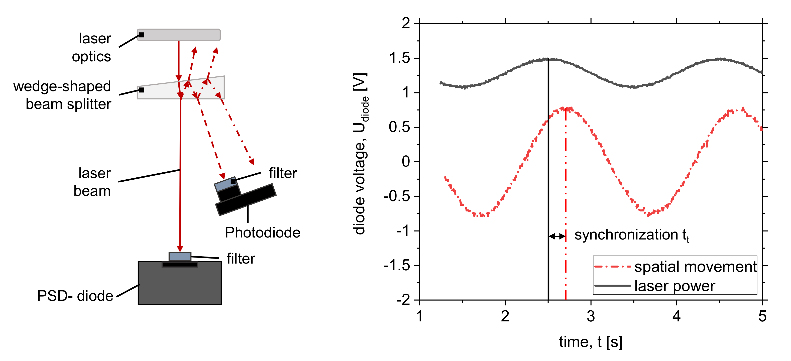
2.3. Experimental Setup for Synchronizing Temporal and Spatial Power Modulation

For superposition of the temporal with the spatial power modulation and detailed synchronization, an experimental setup like the one shown in Figure 6 (left) is needed.
The setup allows synchronizing the laser power modulation with the spatial location of the laser beam on the surface. Therefore, a PSD diode (Hamamatsu C10443-03) and a photodiode (Thorlabs DET10A2) are used. These diodes allow capturing both the change in laser beam intensity (photodiode) as well as the location of the laser beam on a 12 × 12 mm2 diode (PSD-diode). Both signals are captured with an oscilloscope DSO-X 2002A. In the diagram (Figure 6, right), the phase difference of the temporal and the spatial modulation can be analyzed. The constant phase difference evoked by the technical equipment of the experimental setup can then be equalized by either increasing or reducing the phase of the temporal power modulation to match the movement of the laser scanner.

2.4. Experimental Setup for Measuring of Laser Energy Coupling

For analyzing the totally absorbed energy during the laser welding process, the reflected laser power from the material surface has to be measured. The reflected laser power is observed with two integrating spheres (refer to [26,28]). The material sample is placed inside the lower integrating sphere (819C-SF-4, Newport Corporation, Irvine, CA, USA). Due to the position, the diffusely reflected radiation can be measured with a photodiode in the lower sphere. The coaxial reflected radiation is deflected via a beam splitter (Thorlabs BSN11, Thorlabs, Newton, NJ, USA) in the upper integrating sphere (819D-SF-4, Newport Corporation). The beam splitter has a transmission of 89.14% and a reflectivity of 10.86%. The measurements in the two integrating spheres are performed with Si-photodiodes (Thorlabs DET10A2). Both photodiodes are equipped with a bandpass filter (Thorlabs FB1070-10) for noise suppression. With optical filters of known density (Thorlabs NEK01), the measurement signals at the photodiodes are further reduced in case of signal overload. The two signals are monitored using an InfiniiVision DSO-X 2002A oscilloscope from Agilent Technologies (Santa Clara, CA, USA). To assign a respective laser power to a measured photodiode signal, a calibration was conducted before the measurements. After a calibration measurement with a broadband mirror (Thorlabs BB05-E02) tilted by 8° the diode voltage of the lower photodiode can be assigned to specific laser power. In order to take into account the radiation reflected vertically from the lower integrating sphere into the upper integrating sphere during the welding process, the diode voltage of the upper photodiode is also measured with a horizontally positioned mirror. With the measured diode voltages, the absorptivity coefficient η can be calculated [14,15,26,28].

3. Results

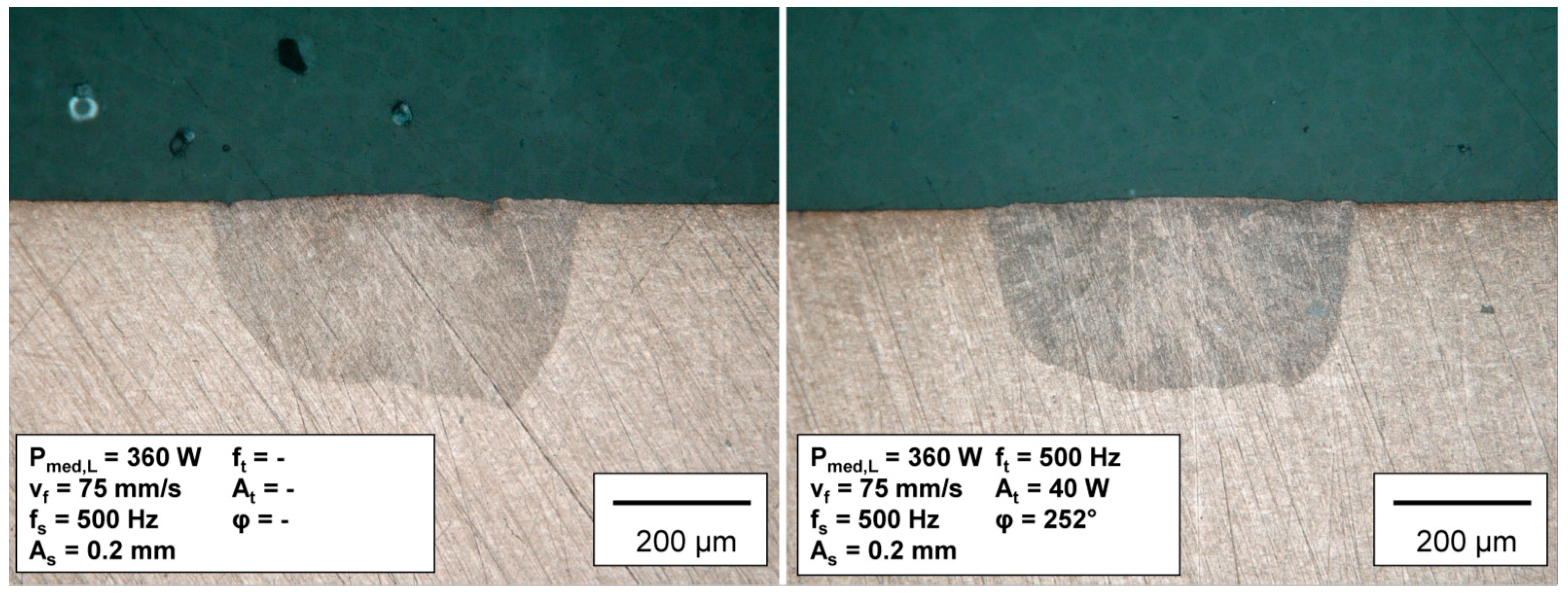
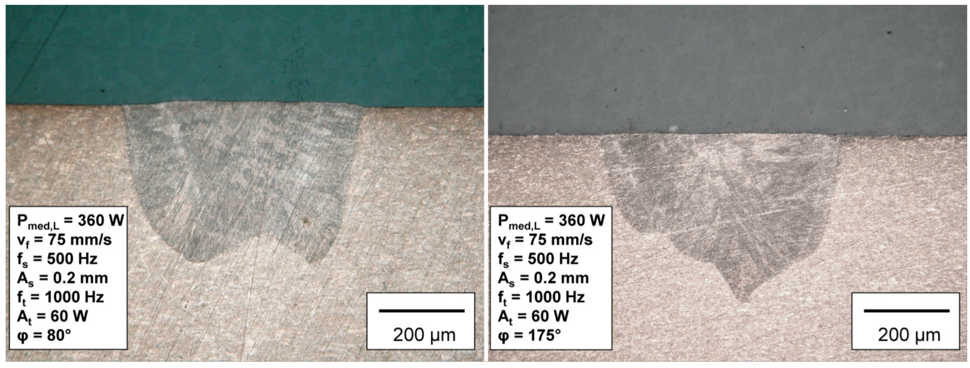
3.1. Bed on Plate Weld on Copper CuSn6

In this section, the most representative parameters with the most distinctive details are presented. First, the initial situation is shown compared to the approach for compensating the difference in weld depth. Figure 7, left, shows a weld with spatial power modulation only.
The slanted seam base is clearly visible. As in the state of the art mentioned, the tilting is pronounced on the side with the higher energy per unit length (lower path velocity). A tilting of this kind would, in the worst case, lead to the destruction of the component, especially on components with only thin substrate layers and an underlying sensitive layer. Therefore, precise control of the welding depth is necessary. This has been achieved in Figure 7, right, by superimposing local and temporal power modulation. The synchronized superimposition of the temporal power modulation with an amplitude of ±40 W visibly compensates for the tilting. The tilt could be reduced from 22.5% to 14%, measured with the welding depth on the right and left side. For the generation of a perfectly rectangular seam cross-section, a more precise parameter study and further optimizations of the process control strategies are necessary.
In order to obtain further degrees of freedom in the production of components, the variable adjustment of the seam cross-section is also considered. The generated cross-section profiles with W- and V-shape are shown in Figure 8.
The weld seam in Figure 8, left shows a region of minimum weld penetration surrounded by two regions of maximum weld penetration. The two sides of the profile are approximately the same depth, which indicates that the energy balance by means of a power amplitude of ±60 W is sufficient. It can also be seen that the left side of the profile is somewhat wider and more voluminous. Here, the process control does not yet seem to have been ideal in order to produce an absolutely symmetrical profile. The temporal modulation of the laser power should be done here via a non-symmetrical sine modulation in order to compensate for the differences in the path velocity. Similar behavior can be noted when creating the V-profile. A clear indentation in the middle area of the weld seam can be seen. The flanks that are welded less deeply towards the outside form the V-profile. However, asymmetrical behavior is also clearly visible here. The maximum depth of the weld is not in the centre but shifts to the right of the center line on the side of the minimum feed rate. Here, a shift of the maximum power further to the side of the maximum feed rate is obviously necessary. However, the other parameters examined did not provide such a clear V-shape. A stronger modulation of the laser power > ±60 W would certainly lead to more reproducible and stronger pronounced results.

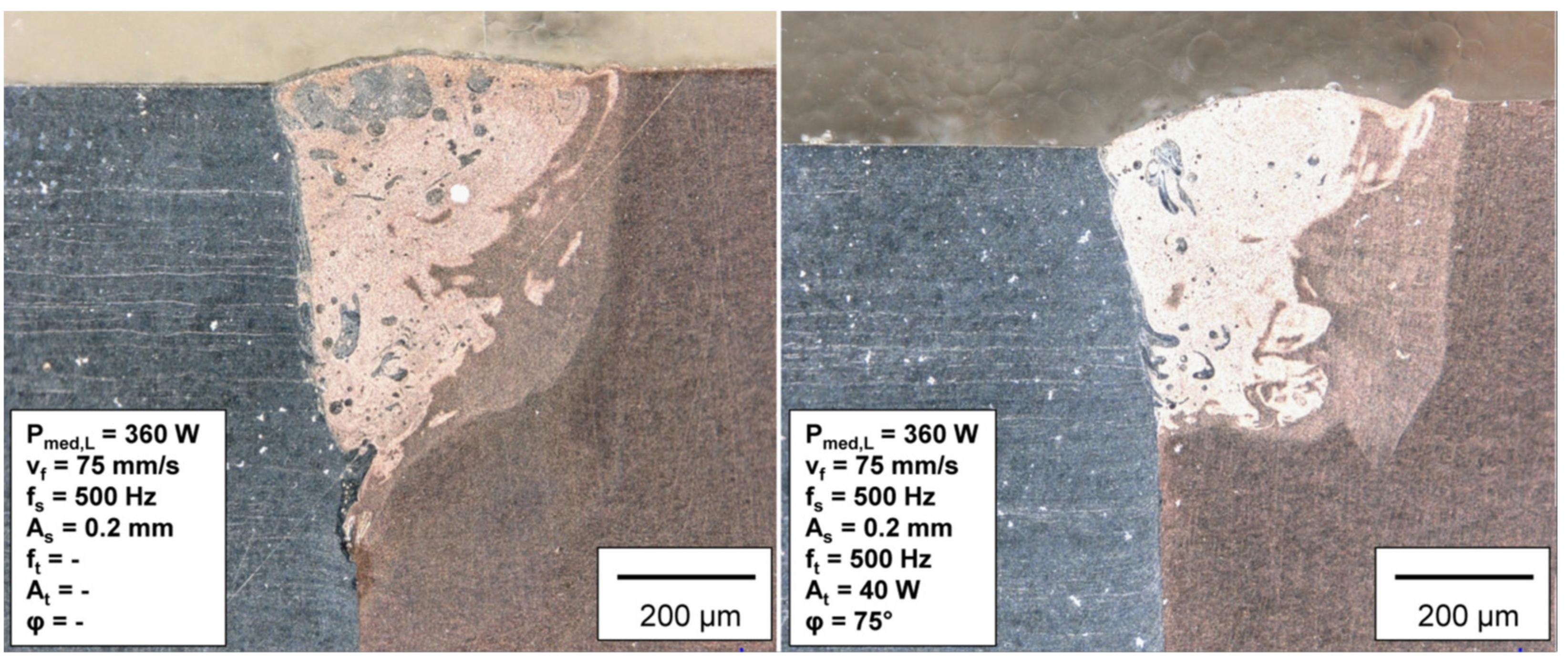
3.2. Dissimilar Welds of CuSn6 Copper and 1.4301 Stainless Steel in Butt Joint Configuration

When welding two different components in a butt joint configuration with local power modulation, the molten metals intermix due to the fluid dynamics of the circulating molten pool. The resulting weld seams are shown in Figure 9 and Figure 10.
While in the bed on plate welding tests with local power modulation, a difference in weld depth with a maximum depth on the right side of the weld (location of lowest path velocity) is observed; this is inverse in the case of these butt joints, even though the spatial power modulation alone was not changed. Due to the material properties of copper and stainless steel, in particular the lower absorption coefficient and higher thermal conductivity of copper compared to stainless steel, the maximum depth is on the side of the stainless steel and thus in the region of maximum path velocity.
Applying combined power modulation to the specimens, the difference in depth can be compensated in the same way as for the bed on plate welds. It can be seen that ±40 W is already sufficient to almost completely compensate or even invert (the copper material is positioned higher than the steel Figure 9, right) the effect of the depth difference on the stainless steel and copper sides. To make the effect clearer, a larger spatial amplitude of 0.3 mm is also examined.
The aspect ratio of the weld decreases with the larger amplitude As in Figure 10 compared to Figure 9. The weld is wider, and the depth is shallower. This circumstance arises from the application of the same energy to a larger surface area on the material. Both welds show a clearly reduced difference in the weld penetration depth due to the combined power modulation. The difference in welding depth within the investigated parameter set was reduced up to 39% compared to the butt joint without combined power modulation.
Problematic for the welding tests in the butt joint configuration is the positioning and alignment of the specimens to the laser beam. This is a source of error in the experimental procedure, which is clearly shown in Figure 9, right. The weld is not centered on the butt edge, and most of the weld is in the copper sheet. Despite this defect, the weld has a compensated difference in weld penetration depth. This fact advocates for the choice of the modulation method for adaptation in multi-material combinations. However, in a butt joint configuration where the materials are arranged the other way round, the position of the laser power maxima and minima would, of course, have to be reversed as well.

4. Discussion

In the following, the degree of energy coupling for the four bed on plate welds is shown to discuss the results obtained with the superpositioned power modulation method. The above-shown results are analyzed in detail as these show the best results of the respective targeted weld-in profiles for the investigated parameter set. Figure 11 shows the temporal course of the coupling degree of the welding process for all four weld seams.
The left diagram shows the time course over an interval of 20 ms from a stabilized process with spatial power modulation and the combined power modulation (compensation). The temporal course of the coupling degree during welding with local power modulation (black graph) corresponds to a periodic oscillation with the frequency of the local modulation (500 Hz). The oscillation behavior of the degree of coupling has its origin in the periodic change of the path velocity within an oscillation loop where the depth of the vapor capillary changes due to the multiple crossing of areas in the weld seam and thus the total absorbed energy inside the vapor capillary is differing. In addition to the periodic oscillation, microscopic fluctuations in the order of microseconds can be detected. The average degree of coupling of this welding test over a measuring time of 20 ms is η = 66.20% ± 2.25%. The peak coupling degree occurs at the maximum energy per unit length, which is reached at a phase angle of 90° on the local scale since the path velocity is lowest there. This is the reference for the following shifts of the temporal course of the coupling degree due to the different modulation types.
The red graph (dot stroke line Figure 11, left) shows the temporal course of the coupling degree of the compensation profile. The curve corresponds to the temporal modulation of a sinusoidal oscillation. The average degree of coupling is η = 66.03% ± 4.82%. With a constant mean value, the amplitude increases due to the amplitude of the local power modulation. The superposition of the local and temporal power modulation can be significantly recognized by the shifted course. The temporal course of the combined modulation is shifted by −0.787 ms or −141.6° compared to the course of the local modulation. This means that the location of the maximum energy coupling on the material surface is shifted towards the location of the maximum path velocity. The graph of the combined modulation additionally does not show any microscopic fluctuations in the microsecond range. The superposition of the spatial and temporal power modulation imposes a power setting and thus a predetermined movement on the vapor capillary to stabilize it and thus influence the energy input into the process.
Figure 11, right, shows the temporal courses of the coupling degrees of the W- and the V-profile. As the graph of the compensation profile, these show a sinusoidal curve but with a temporal frequency of 1000 Hz. The frequency of the temporal modulation is twice as large as the frequency of the spatial modulation. The amplitude of the energy coupling increases further for both profiles due to the higher temporal power modulation of ±60 W. The respective course of the degree of coupling is smoothed and the welding process further stabilized. The two curves are shifted relative to each other by approx. π (90°) on the time scale, which corresponds to the phase shift of the power maxima of the profiles relative to each other. The superposition of the local modulation and the temporal modulation with double the frequency can be recognized by the periodically changing magnitude of the maxima and minima of the coupling degree of the W-profile and the V-profile.

5. Conclusions

The following conclusions can be drawn from this work:
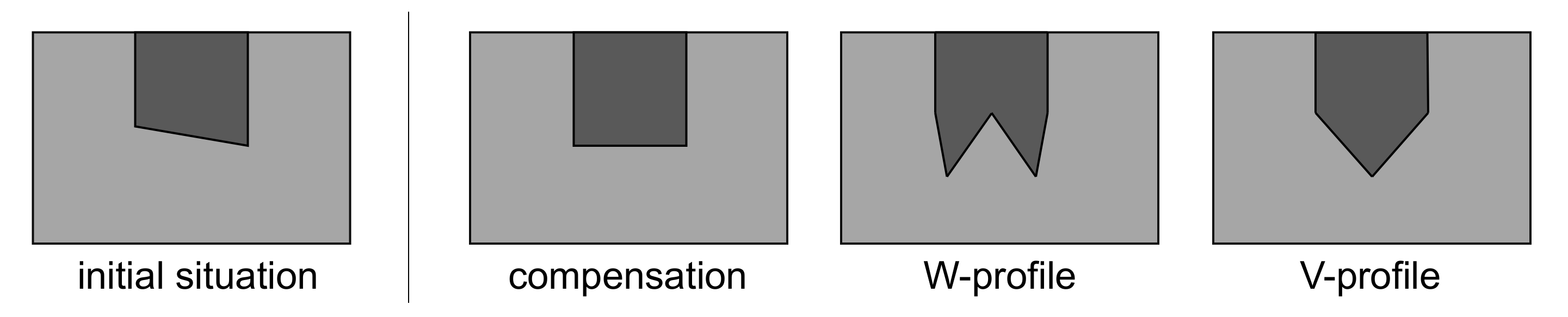
  • Based on the standard weld seam, it has been shown that in addition to compensating for seam tilt, it is also possible to create other cross-section profiles such as W and V shapes.
  • The feasibility to control the laser energy deposition during laser micro welding by means of synchronized temporal and spatial power modulation is shown.
  • The difference in the welding depth could be reduced in the parameter space examined in this work by 8.5%-points for bed on plate welds on CuSn6 and by 39% points for dissimilar material systems in the butt joint configuration between 1.4301 and CuSn6.
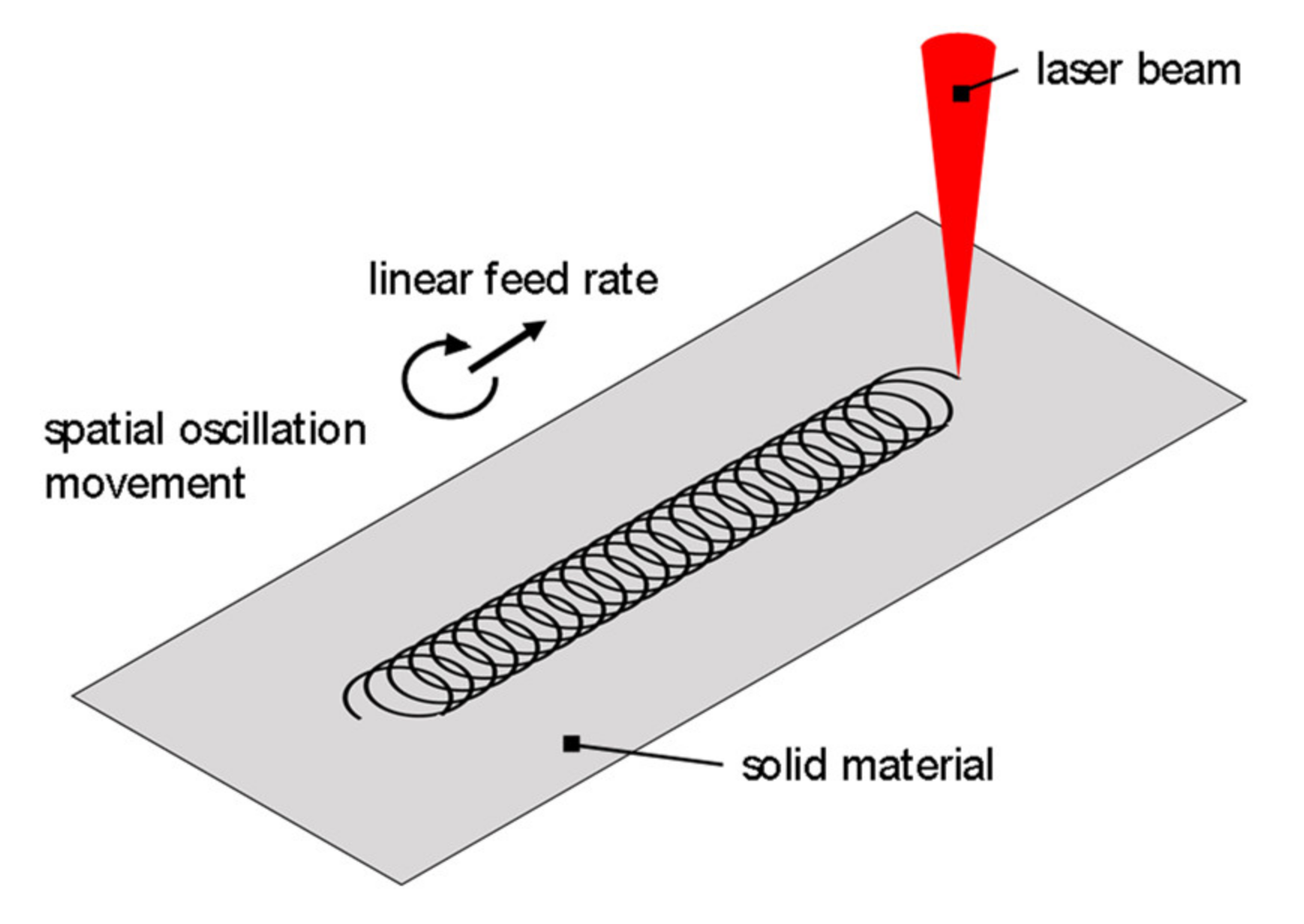
  • A variation of the position of maximum and minimum laser power on the weld seam is crucial for successful adjustment of the weld seam geometry.
  • Measurement of energy coupling during the welding process can be used to analyze changes in the energy coupling due to modified power modulation in detail.
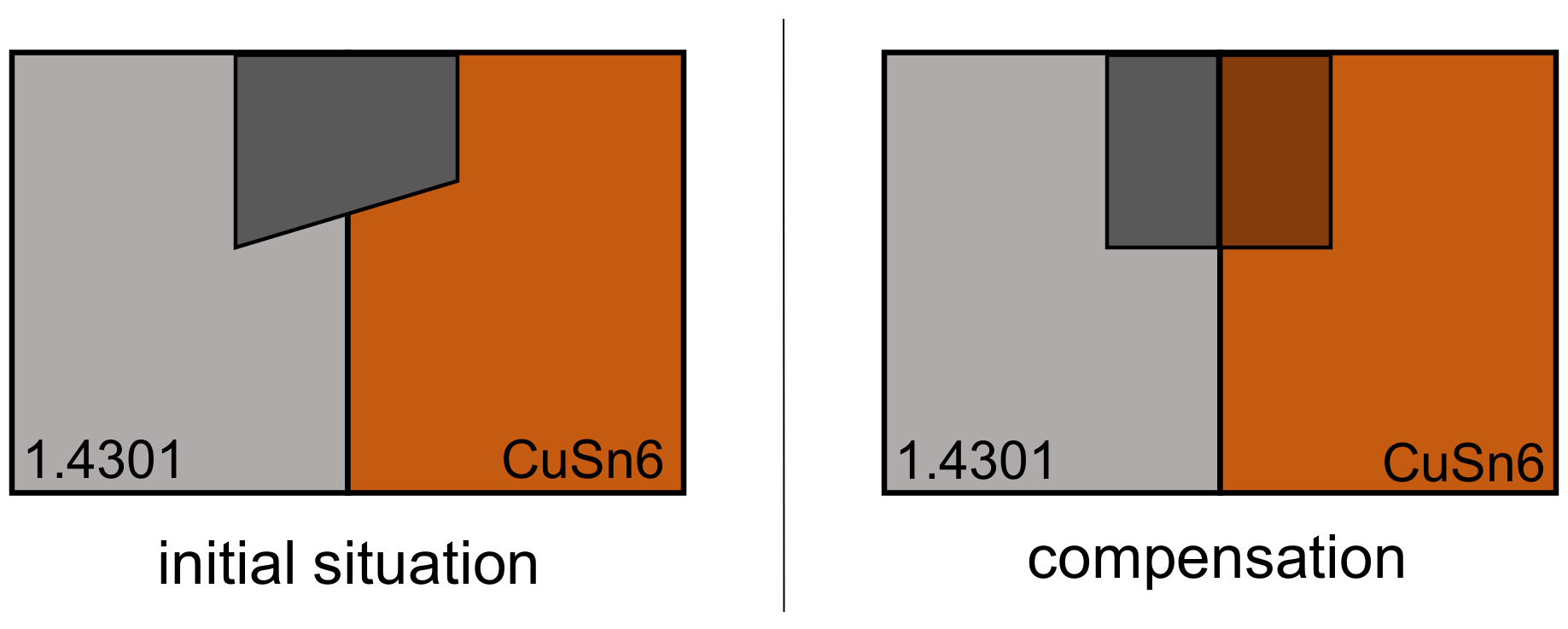
  • The uneven welding depth in butt joints of dissimilar materials can be compensated by exposing higher laser power on the material with increased thermal conductivity and reflectivity and vice versa.
In further research work, a more detailed parameter study has to be conducted to find optimized parameters for the butt joint equalization. Additionally, the sinusoidal curve of the temporal power modulation must be extended by peaks of different heights in order to compensate for the non-symmetrically change in path velocity on the material surface to the right extent.

Author Contributions

Conceptualization, M.H., A.H. and A.G.; methodology, M.H., A.H. and A.G.; validation, M.H. and A.H.; formal analysis, M.H.; investigation, M.H.; writing—original draft preparation, M.H.; writing—review and editing, A.H.; visualization, M.H.; supervision, A.G.; project administration, A.G.; funding acquisition, A.G. All authors have read and agreed to the published version of the manuscript.

Funding

The presented investigations were carried out at RWTH Aachen University within the framework of the Collaborative Research Center SFB-1120-236616214 “Bauteilpräzision durch Beherrschung von Schmelze und Erstarrung in Produktionsprozessen” and funded by the Deutsche Forschungsgemeinschaft e.V. (DFG, German Research Foundation). The sponsorship and support are gratefully acknowledged.

Data Availability Statement

The data presented in this study are available on request from the corresponding author. The data are not publicly available.

Conflicts of Interest

The authors declare no conflict of interest. The funders had no role in the design of the study; in the collection, analyses, or interpretation of data; in the writing of the manuscript, or in the decision to publish the results.

References

  1. Heinen, P.; Haeusler, A.; Mehlmann, B.; Olowinsky, A. Laser Beam Micro welding of Lithium-ion Battery Cells with Copper Connectors for Electrical Connections in Energy Storage Devices. Laser Eng. 2017, 36, 147–167. [Google Scholar]
  2. Mehlmann, B.; Gehlen, E.; Olowinsky, A.; Gillner, A. Laser Micro Welding for Ribbon Bonding. Physics Procedia 2014, 56, 776–781. [Google Scholar] [CrossRef]
  3. De Bono, P.; Blackburn, J. Laser welding of copper and aluminium battery interconnections. In Proceedings of the Industrial Laser Applications Symposium 2015, Kenilworth, UK, 17 March 2015; p. 96570M. [Google Scholar]
  4. Gedicke, J.; Mehlmann, B.; Olowinsky, A.; Gillner, A. Laser beam welding of electrical interconnections for lithium-ion batteries. In Proceedings of the 29th International Congress on Applications of Lasers & Electro-Optics (ICALEO 2010), Anaheim, CA, USA, 26–30 September 2010. [Google Scholar] [CrossRef]
  5. Heider, A.; Stritt, P.; Hess, A.; Weber, R.; Graf, T. Process Stabilization at welding Copper by Laser Power Modulation. Physics Procedia 2011, 12, 81–87. [Google Scholar] [CrossRef] [Green Version]
  6. Kang, M.; Han, H.N.; Kim, C. Microstructure and Solidification Crack Susceptibility of Al 6014 Molten Alloy Subjected to a Spatially Oscillated Laser Beam. Materials 2018, 11, 648. [Google Scholar] [CrossRef] [PubMed] [Green Version]
  7. Punzel, E.; Hugger, F.; Dörringer, R.; Dinkelbach, T.L.; Bürger, A. Comparison of different system technologies for continuous-wave laser beam welding of copper. Procedia CIRP 2020, 94, 587–591. [Google Scholar] [CrossRef]
  8. Schmitt, F.; Mehlmann, B.; Gedicke, J.; Olowinsky, A.; Gillner, A.; Poprawe, R. Laser Beam Micro Welding with High Brilliant Fiber Lasers. J. Laser Micro/Nanoeng. 2010, 5, 197–203. [Google Scholar] [CrossRef]
  9. Schmitt, F. Laserstrahl-Mikroschweißen mit Strahlquellen hoher Brillanz und örtlicher Leistungsmodulation; Shaker: Aachen, Germany, 2012; ISBN 3844010416. [Google Scholar]
  10. Jarwitz, M.; Fetzer, F.; Weber, R.; Graf, T. Weld Seam Geometry and Electrical Resistance of Laser-Welded, Aluminum-Copper Dissimilar Joints Produced with Spatial Beam Oscillation. Metals 2018, 8, 510. [Google Scholar] [CrossRef] [Green Version]
  11. Aden, M.; Heinen, P.; Olowinsky, A. Seam Formation in Laser Beam Micro-Welding with Spatial Power Modulation. Lasers Manuf. Mater. Process. 2021, 8, 60–72. [Google Scholar] [CrossRef]
  12. Mrna, L.; Horník, P.; Jedlicka, P.; Pavelka, J. Study of laser wobbling welding process through the radiation of plasma plume. In Proceedings of the Laser in Manufacturing Conference, Munich, Germany, 26–29 June 2017. [Google Scholar]
  13. Häusler, A.; Mehlmann, B.; Olowinsky, A.; Gillner, A.; Poprawe, R. Efficient Copper Micro welding with Fibre Lasers using Spatial Power Modulation. Laser Eng. 2017, 36, 133–146. [Google Scholar]
  14. Häusler, A. Präzisionserhöhung beim Laserstrahl-Mikroschweißen Durch Angepasstes Energiemanagement, 1st ed.; Aprimus Verlag: Aachen, Germany, 2021; ISBN 978-3-86359-933-1. [Google Scholar]
  15. Conzen, J.H.; Haeusler, A.; Stollenwerk, J.; Gillner, A.; Poprawe, R.; Loosen, P. Laserstrahl-Mikroschweißen von Mikroelektronische Baugruppen unter Anwendung von Örtlicher und Zeitlicher Energiedeposition; Elektronische Baugruppen und Leiterplatten EBL: Düsseldorf, Germany, 2018. [Google Scholar]
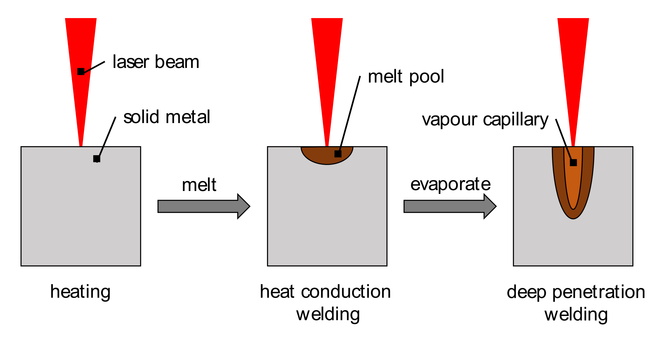
  16. Stritt, P.; Weber, R.; Graf, T.; Müller, S.; Ebert, C. Utilizing Laser Power Modulation to Investigate the Transition from Heat-Conduction to Deep-Penetration Welding. Physics Procedia 2011, 12, 224–231. [Google Scholar] [CrossRef] [Green Version]
  17. Kraetzsch, M.; Standfuss, J.; Klotzbach, A.; Kaspar, J.; Brenner, B.; Beyer, E. Laser beam welding with high-frequency beam oscillation: Welding of dissimilar materials with brilliant fiber lasers. Physics Procedia 2011, 12, 142–149. [Google Scholar] [CrossRef]
  18. Chen, X.; Jiang, M.; Chen, Y.; Lei, Z.; Zhao, S.; Lin, S. Laser welding-brazing under temporal and spatial power modulation for dissimilar materials AA6061 to Ti6Al4V joints. Manuf. Lett. 2021, 29, 70–73. [Google Scholar] [CrossRef]
  19. Hügel, H.; Graf, T. Laser in der Fertigung: Grundlagen der Strahlquellen, Systeme, Fertigungsverfahren, 2nd ed.; Springer: Wiesbaden, Germany, 2009; ISBN 978-3-8348-9570-7. [Google Scholar]
  20. Engler, S.; Ramsayer, R.; Poprawe, R. Process Studies on Laser Welding of Copper with Brilliant Green and Infrared Lasers. Physics Procedia 2011, 12, 339–346. [Google Scholar] [CrossRef]
  21. Beck, M. Modellierung des Lasertiefschweißens; Teubner: Stuttgart, Germany, 1996; ISBN 978-3519062189. [Google Scholar]
  22. Mehlmann, B. Spatially Modulated Laser Beam Micro Welding of CuSn6 and Nickel-plated DC04 Steel for Battery Applications. JLMN 2014, 9, 276–281. [Google Scholar] [CrossRef] [Green Version]
  23. Schweier, M.; Heins, J.F.; Haubold, M.W.; Zaeh, M.F. Spatter Formation in Laser Welding with Beam Oscillation. Physics Procedia 2013, 41, 20–30. [Google Scholar] [CrossRef] [Green Version]
  24. Franco, D.F. Wobbling Laser Beam Welding of Copper. Master’s Thesis, Universidad Nova de Lisboa, Lisbon, Portugal, September 2017. [Google Scholar]
  25. Häusler, A.; Schürmann, A.; Schöler, C.; Olowinsky, A.; Gillner, A.; Poprawe, R. Quality improvement of copper welds by laser microwelding with the usage of spatial power modulation. J. Laser Appl. 2017, 29, 22422. [Google Scholar] [CrossRef]
  26. Hummel, M.; Häusler, A.; Olowinsky, A.; Gillner, A.; Poprawe, R. Comparing 1070 nm and 515 nm Wavelength Laser Beam Sources in Terms of Efficiency for Laser Micowelding Copper. Lasers Eng. 2020, 46, 187–202. [Google Scholar]
  27. Warlimont, H.; Martienssen, W. Springer Handbook of Materials Data; Springer International Publishing: Cham, Switzerland, 2018; ISBN 978-3-319-69741-3. [Google Scholar]
  28. Hummel, M.; Schöler, C.; Häusler, A.; Gillner, A.; Poprawe, R. New approaches on laser micro welding of copper by using a laser beam source with a wavelength of 450 nm. J. Adv. Join. Process. 2020, 1, 100012. [Google Scholar] [CrossRef]
Figure 1. Illustration of process regimes (heat conduction and deep penetration welding) after [20].
Jmmp 05 00127 g001
Figure 2. Illustration of spatial power modulation for laser beam micro welding.
Jmmp 05 00127 g002
Figure 3. Schematic representation of the weld-in profiles to be investigated in transverse section. Initial situation (left); compensation and targeted profiles with combined power modulation (right).
Jmmp 05 00127 g003
Figure 4. Schematic representation of the weld penetration profile of a weld in the butt joint of dissimilar joining partners and the compensated target situation using combined power modulation.
Jmmp 05 00127 g004
Figure 5. Qualitative representation of the position of the maximum and minimum laser power; red—maximum power; blue—minimum power.
Jmmp 05 00127 g005
Figure 6. Schematic experimental setup for synchronizing temporal and spatial power modulation (left); measured signals to determine the phase shift tz (right).
Jmmp 05 00127 g006
Figure 7. Left: Laser weld with only spatial power modulation. Right: Laser weld with combined spatial and temporal power modulation (compensation).
Jmmp 05 00127 g007
Figure 8. Laser weld with combined spatial and temporal power modulation Left: W-shape; Right: V-shape.
Jmmp 05 00127 g008
Figure 9. Comparison of two welds in butt joint. Left: with local PM; right: with combined PM with local amplitude As = 0.2 mm.
Jmmp 05 00127 g009
Figure 10. Comparison of two weld seams in the butt joint. Left: with local PM; right: with combined PM with an amplitude of As = 0.3 mm.
Jmmp 05 00127 g010
Figure 11. Temporal course of the coupling degrees for bed on plate welds on CuSn6. Left: spatial PM only and combined PM (compensation); Right: W- and V- profile.
Jmmp 05 00127 g011
Table 1. Optical and thermal material properties of CuSn6 and 1.4301 stainless steel [20,26,27].
Material PropertyCuSn61.4301
Absorptivity (λ = 1064 nm)7.9%37.2%
Heat conductivity75 W/mK15 W/mK
Heat capacity377 J/kgK500 J/kgK
Liquidus temperature1323 K1673 K
Table 2. Parameters for the investigated laser welding modulation method.
Profile/WeldFeed RateAverage Laser PowerFrequency TemporalAmplitude TemporalFrequency SpatialAmplitude Spatial
Initial75 mm/s360 W500 Hz40 W500 Hz0.2 mm
Compensation75 mm/s360 W500 Hz40 W500 Hz0.2 mm
W-profile75 mm/s360 W1000 Hz60 W500 Hz0.2 mm
V-profile75 mm/s360 W1000 Hz60 W500 Hz0.2 mm
Dissimilar material75 mm/s360 W500 Hz40 W500 Hz0.2/0.3 mm
Table 3. Areas on the oscillation profile for variation of the temporal power modulation.
ProfileMaximum Laser PowerMinimum Laser Power
Compensationφ = 255–285°φ = 75–105°
W-profileφ = 75–105°/255–285°φ = 165–195°/345–375°
V-profileφ = 165–195°/345–375°φ = 75–105°/255–285°
Publisher’s Note: MDPI stays neutral with regard to jurisdictional claims in published maps and institutional affiliations.

