Article

Thermomechanical Impact of the Single-Lip Deep Hole Drilling on the Surface Integrity on the Example of Steel Components

1
Institute of Machining Technology (ISF), TU Dortmund University, Baroper Str. 303, 44227 Dortmund, Germany
2
Department of Materials Test Engineering, TU Dortmund University, Baroper Str. 303, 44227 Dortmund, Germany
*
Author to whom correspondence should be addressed.
J. Manuf. Mater. Process. 2021, 5(4), 120; https://doi.org/10.3390/jmmp5040120
Submission received: 27 September 2021 / Revised: 29 October 2021 / Accepted: 4 November 2021 / Published: 9 November 2021
(This article belongs to the Special Issue Surface Integrity in Machining and Post-processing)

Abstract

:
The fatigue behavior of components made of quenched and tempered steel alloys is of elementary importance, especially in the automotive industry. To a great extent, the components’ fatigue strength is influenced by the surface integrity properties. For machined components, the generated surface is often exposed to the highest thermomechanical loads, potentially resulting in transformations of the subsurface microstructure and hardness as well as the residual stress state. While the measurement of the mechanical load using dynamometers is well established, in-process temperature measurements are challenging, especially for drilling processes due to the process kinematics and the difficult to access cutting zone. To access the impact of the thermomechanical load during the single-lip drilling process on the produced surface integrity, an in-process measurement was developed and applied for different cutting parameters. By using a two-color pyrometer for temperature measurements at the tool’s cutting edge in combination with a dynamometer for measuring the occurring force and torque, the influence of different cutting parameter variations on the thermomechanical impact on the bore surface are evaluated. By correlating force and temperature values with the resultant surface integrity, a range of process parameters can be determined in which the highest dynamic strength of the samples is expected. Thermally induced defects, such as the formation of white etching layers (WEL), can be avoided by the exact identification of critical parameter combinations whereas a mechanically induced microstructure refinement and the induction of residual compressive stresses in the subsurface zone is targeted. Further, eddy-current analysis as a non-destructive method for surface integrity evaluation is used for the characterization of the surface integrity properties.

1. Introduction

Quenched and tempered steels such as AISI 4140 (42CrMo4 + QT, 1.7225) are widely used in industrial applications where components are subjected to high static or dynamic loads. The fatigue performance of machined components is highly influenced by its surface integrity, which is referred to as the unimpaired or enhanced surface condition which is developed in a component by controlled manufacturing processes by [1]. The main characteristics, that are used to describe the surface integrity are the surfaces’ topography, and the microstructure, hardness, and residual stresses of the surface layers [2]. For hydraulic components, such as fuel injectors or fuel distribution systems in the automotive industry, or components such as valves in high-pressure hydraulic applications in mechanical engineering, the inner surface is critical for fatigue strength. Since these surfaces of the components are often subjected to high dynamic loads, it is highly important to specify and apply a manufacturing process to avoid any damage in the surface and rather specify a process that will even enhance a parts fatigue performance [1]. For the single lip-deep hole drilling process, this objective is part of a current research project. In previous studies of the authors on the single-lip drilling of steel components it could be shown that the surface integrity of bores is strongly influenced by the process parameters, such as tool design, feed rate, and cutting velocity, during the drilling of the bore. By varying the process parameters and therefore increasing the mechanical impact on the bore wall, an increased hardening of the bore subsurface in combination with a refinement of the subsurface microstructure and the induction of compressive residual stresses could be achieved [3,4,5]. In industrial applications, similar surface strengthening effects, which are caused by a plastic deformation of the bore surface, are often achieved by applying surface treatment methods after the drilling process, such as a hydraulic autofrettage process [2,6]. By specifying optimized parameters for the drilling process, the fatigue strength of components should be improved, so that a subsequent surface treatment process can be obsolete for some applications. Single-lip drilling was identified as particularly effective for this purpose, since the asymmetrical design of the tool has the effect that a large part of the cutting forces are transmitted to the bore wall via the tool’s guide pads [7]. Alongside the mechanical loads, the thermal loads occurring during machining process also affect the resultant surface integrity. Of particular interest for the single-lip drilling process are the maximum temperatures that occur in the cutting zone. Excessive thermal loads are known to result in phase transformations in the bores’ subsurface layer, causing the formation of thermally induced brittle layers. In metallographic microstructural analyses, these areas appear as white etching layers (WEL) at the edge of the bore wall. WEL are often accompanied by the induction of undesirable tensile residual stresses and so are highly critical for the components fatigue performance. A threshold for the formation of WEL is the austenitizing temperature of the workpiece material. If this temperature is reached or exceeded, the subsurface microstructure can be austenitized for a brief moment and then transformed into a martensitic microstructure by subsequent quenching with the cooling lubricant [1,8,9]. Despite the relevance for the quality of the produced surfaces, the thermal loads acting onto the bores’ surface and subsurface during single-lip deep hole drilling are largely unexplored to date. Therefore, the assessment of thermal and mechanical loads in superposition onto the bore wall is part of this paper and will be discussed for different cutting parameter combinations.

2. Materials and Methods

A high-strength quenched and tempered steel AISI 4140 (42CrMo4 + QT, 1.7225) was selected for the tests, since this material is commonly used in industrial applications with high static and dynamic loads. This specific material has a tensile strength of Rm = 965 MPa. The sulfur content in steel significantly affects the number and size of manganese sulfides, which are the origin of crack formation in fatigue tests can reduce the dynamic strength of a material [10]. In the present case, the steel has a reduced sulfur content of 0.011% by weight (wt %), which favors the possibility of achieving an increase in dynamic strength by means of affecting the surface integrity. The chemical composition of the material is provided in Table 1.
The single-lip deep hole drilling experiments were carried out on a deep drilling machine Type Ixion TLF 1004 from Maschinenfabrik Otto Haefner GmbH & Co. KG, Hamburg, Germany. The coolant lubricant supply through the inner coolant channels of the single-lip drills was kept at a constant pressure of plub = 100 bar for all tests. As a lubricant, the drilling oil Petrofer Isocut T 404 with a viscosity of ν = 10 mm²/s was used.

2.1. Tools

As tools solid carbide single-lip drills type 113HP from botek Praezisionsbohrtechnik GmbH in Riederich, Germany were used. The diameter of the drills is dSLD = 5 mm, since this is a common dimension for bores in hydraulic blocks and systems, such as fuel injection nozzles in automotive industry or valves for plunger pumps in high pressure hydraulics. Given the flute length of lflute = 190 mm, the maximum achievable length to diameter (l/D) ratio of bores for the tools is 38. In previous investigations, it was shown that the tool design in particular is crucial for the height of the mechanical load and the corresponding hardening of the subsurface [3]. In order to increase the normal forces transmitted to the bore wall via the guide pads of the tool, a tool design was selected which has a comparatively large, arc-shaped outer cutting edge. In contrast, the inner cutting edge is relatively small. This tool design results in high passive forces, which are transmitted to the bore wall via the guide pads and lead to plastic deformation of the bore wall. In addition, by choice of a circumferential shape A (according to VDI guideline 3208) with relatively narrow guide pads compared to shape G, the surface pressure is further increased to achieve an even higher mechanical impact on the surface and subsurface. The tool properties as well as geometry are shown in Figure 1. For the purpose of visualization, the positions of the guide pads on the tool are highlighted. Effects of tool wear on the thermomechanical influence on the bore wall were to be minimized in the tests. Therefore, the drill heads were regularly examined under a digital light microscope Keyence (Osaka, Japan) VHX 6000 for signs of wear and, if necessary, replaced with a new tool.

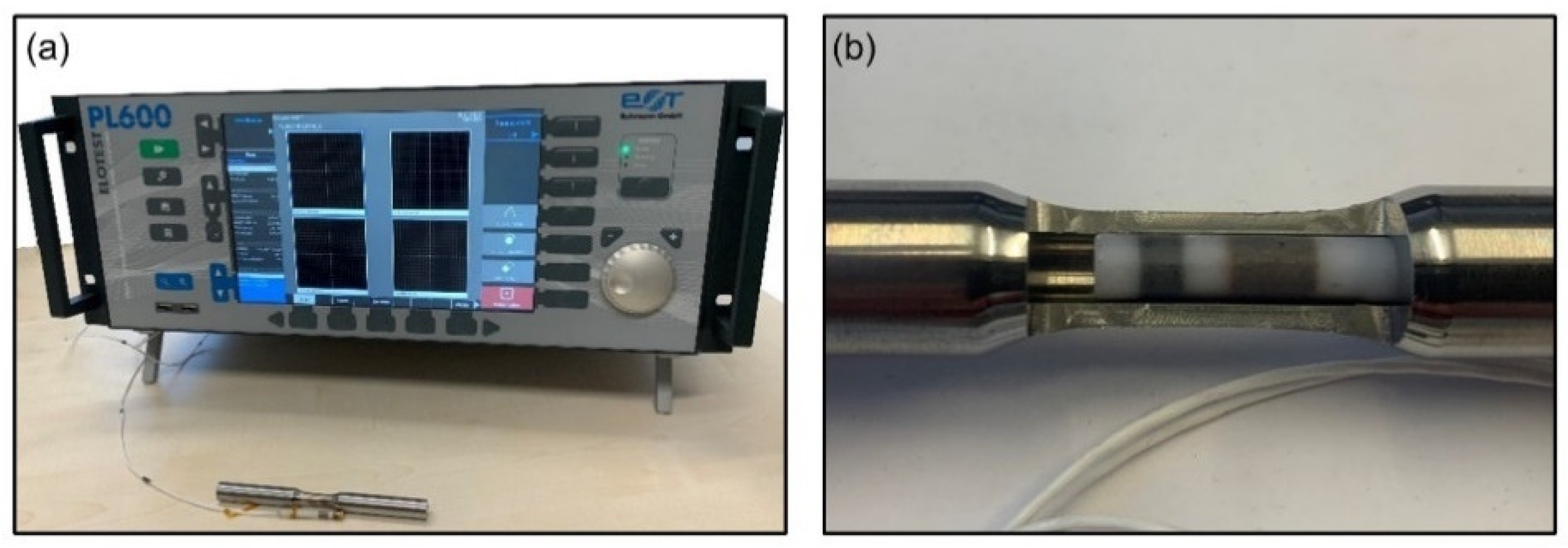
2.2. Mechanical and Thermal Load Measurement

The mechanical load occurring during the drilling process was measured using a type 9123 rotational dynamometer from Kistler Group (Winterthur, Switzerland) with a sampling rate of 5 kHz. The feed force Ff and the drilling torque MD were then evaluated using the DIAdem software from National Instruments. For the assessment of the temperature generated in the cutting zone during the drilling process, an experimental setup was developed which combines two established temperature measurement methods. Since, especially in single-lip drilling, the frictional heat at the guide pads of the tool plays a role in addition to the temperature generated by the cutting process, a pyrometric measurement orthogonal to the bore axis was applied. This allows the temperature to be measured both at the tool cutting edge and at the guide pads. For this measurement setup, a two-color pyrometer type FIRE-3 from en2Aix-energy engineering Aachen GmbH (Aachen, Germany) was used. The sampling rate was set to 7 kHz. In addition to the pyrometric measurement, a thermoelectric measurement with a sampling rate of 5 kHz is applied to measure the temperature in the bores’ subsurface. In preparation for the deep hole drilling tests, three cross bores with a diameter of dCB = 0.4 mm were drilled into the samples, into which two type K thermocouples (TC) and the pyrometer fiber were inserted. Micro precision TiAlN coated carbide twist drills type N from Gühring KG (Albstadt, Germany) were used for this purpose. The pyrometer fiber with a fiber diameter of dF = 0.33 mm was fixed in the cross bore B2 with an adhesive (see Figure 2). This cross bore is drilled to a certain depth so that the pyrometer fiber protrudes with length of lF = 600 μm into drilling path of the single-lip deep hole. This allows the pyrometer fiber to be machined by the tools’ cutting edge during the drilling process in order to measure the temperature on the cutting edge during each tool rotation. Cutting the pyrometer fiber is an established method for the application of a pyrometric measurement in drilling processes, since it offers the advantage that the measurement can be carried out even when using coolant lubricant [11,12,13]. The thermocouples with a diameter of dTC = 0.25 mm were inserted into the cross bores using a thermal conductive paste with a thermal conductivity of λ = 10.5 W/mK. Afterwards, these are fixed in position using the same adhesive X60. The use of a thermal conductive paste leads to a reduction of the recorded measurement deviation tolerance, since the heat transfer between the thermocouple and the material is ensured. Using a stable blackbody furnace, the calibration of the temperature measurement methods was validated before the tests. The temperature measurement sensors are positioned halfway of the drilling path, since this position is of particular importance for the investigations on the fatigue performance of the samples. Figure 2 shows an outline of the measuring positions where the thermocouples (bores B1, B3) and the pyrometry fiber (bore B2) are inserted into the workpiece.
For the thermoelectric measurement in the bores’ subsurface, the two thermocouples were connected to a measuring interface and the temperatures were evaluated via a PC connected to it. The disadvantage of this method is that the temperatures can only be measured at a certain distance from the actual cutting zone. However, the thermoelectrically measured values can be used to validate the pyrometric measurement, which allows the temperature to be detected directly in the contact area between the tool cutting edge and the bore wall. For the pyrometric measurement, the thermal radiation, which is emitted by the cutting of the workpiece material, is transmitted to the pyrometer via the pyrometer fiber. The software of the pyrometer outputs the temperatures based on the voltage signals corresponding to the detected thermal radiation. An overview of the test setup including the equipment used for the temperature and tool load measurement is given in Figure 3.

2.3. Post Process Microstructure Analysis and Eddy-Current Measurement

Eddy-current measurements are well-established for non-destructive material sorting, crack detection and coating thickness measurements. In this work the aim is the evaluation of the surface integrity of the bore wall. The measurements were carried out with an Elotest PL-600 (Rohmann GmbH, Frankenthal, Germany) (Figure 4a) and a tailored 4 mm inner diameter sensor (Figure 4b).
The third harmonic of the eddy-current frequency 900 kHz with a preamplification of 30.50 dB, an amplification of 30.00 dB and a x- and y-spread of 6 dB was considered. For the visualization of the microstructure in the bore subsurface, a Axio Imager M1m (Carl Zeiss AG, Jena, Germany) light microscope as well as a Mira3 (Tescan, Brno-Kohoutovice, Czech Republic) scanning electron microscope were used.

3. Results and Discussion

As previously mentioned, the superposition of thermomechanical loads acting on the bore wall during the drilling process are decisive for the resulting surface integrity. The risk of unintended WEL formation exists especially when the austenitizing temperature is reached or exceeded. Therefore, the maximum temperatures Tmax are the main focus of the analyses when evaluating the temperature measurements. However, the critical threshold for structural microstructure changes is influenced by a superposition of thermal and mechanical loads on the bore’s surface and subsurface, so that the thermomechanical load in conjunction has to be regarded.

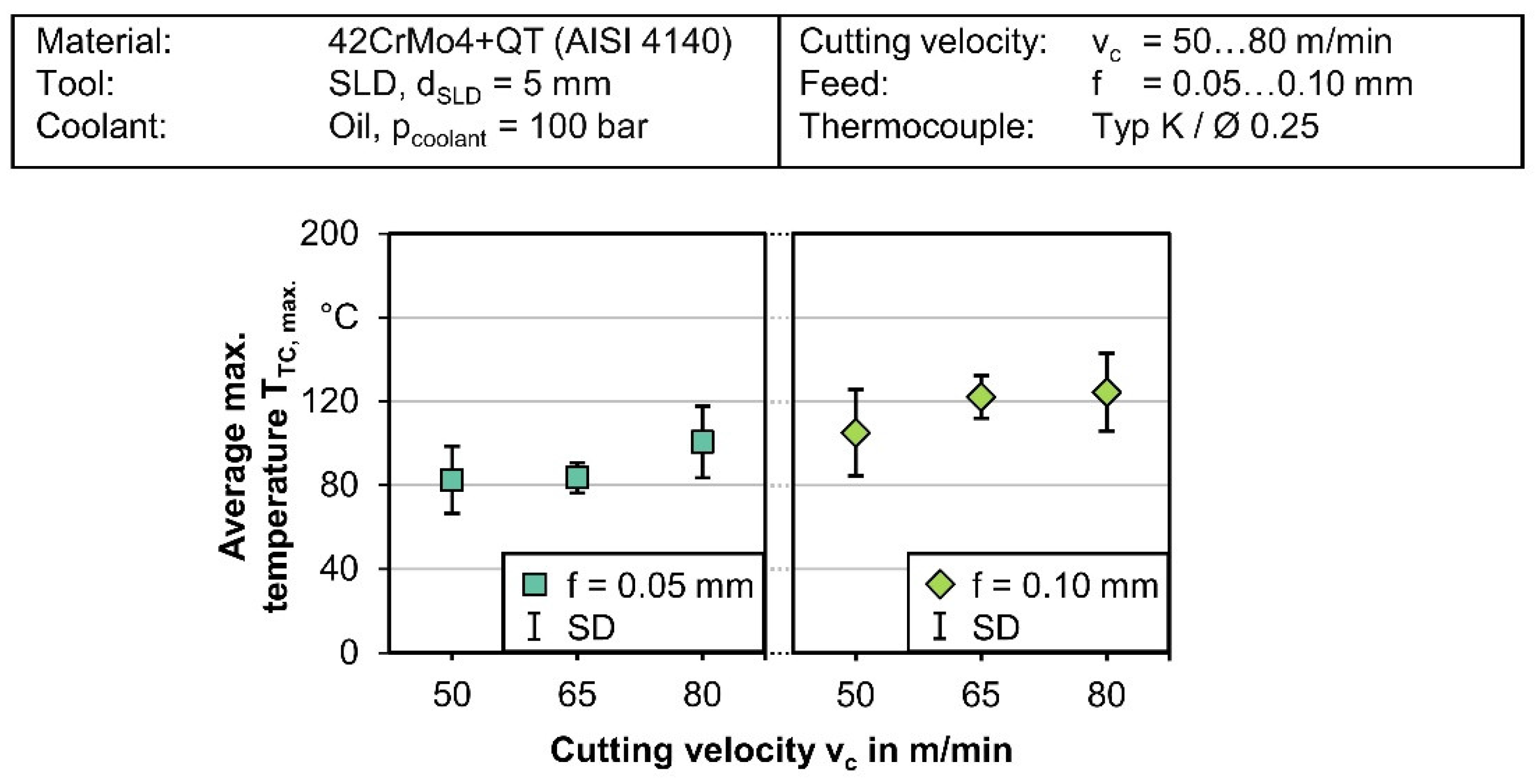
3.1. Thermoelectric In-Process Temperature Measurement

The thermoelectric measurement was carried out for different cutting values, for which the results are shown in Figure 5. For the analysis, 12 measurements were conducted for each combination of cutting values and the maximum temperatures that occurred in each case were evaluated. The diagram shows that the cutting values strongly influence the thermal energy introduced into the bore wall. Increasing the cutting velocity from vc = 50 to 80 m/min results in an increase of the measured maximum temperature by about 20% for both feed rates investigated. A comparison of the two feed rates also shows an increase in the temperature into the bore wall for the higher feed rate. The maximum temperatures for the feed rate f = 0.10 mm and the cutting speeds vc = 65 m/min and 80 m/min are at a similar level of TTC, max. = 122 °C and 124 °C, although the measurements for the higher cutting speed show a greater deviation.
These thermoelectrically measured average maximum temperatures of up to TTC, max. = 124 °C are much lower than temperatures directly in the contact area between the tool and the bore wall the cutting zone. Therefore, the actual temperatures prevalent at the bore surface can only be indirectly concluded by comparison of thermal energy induced into the workpiece material. For a direct measurement of the temperatures acting on the bore wall during the process, the temperature measurement by means of a ratio pyrometer was additionally applied to provide a more detailed access to the thermal load in the tool/workpiece contact area.

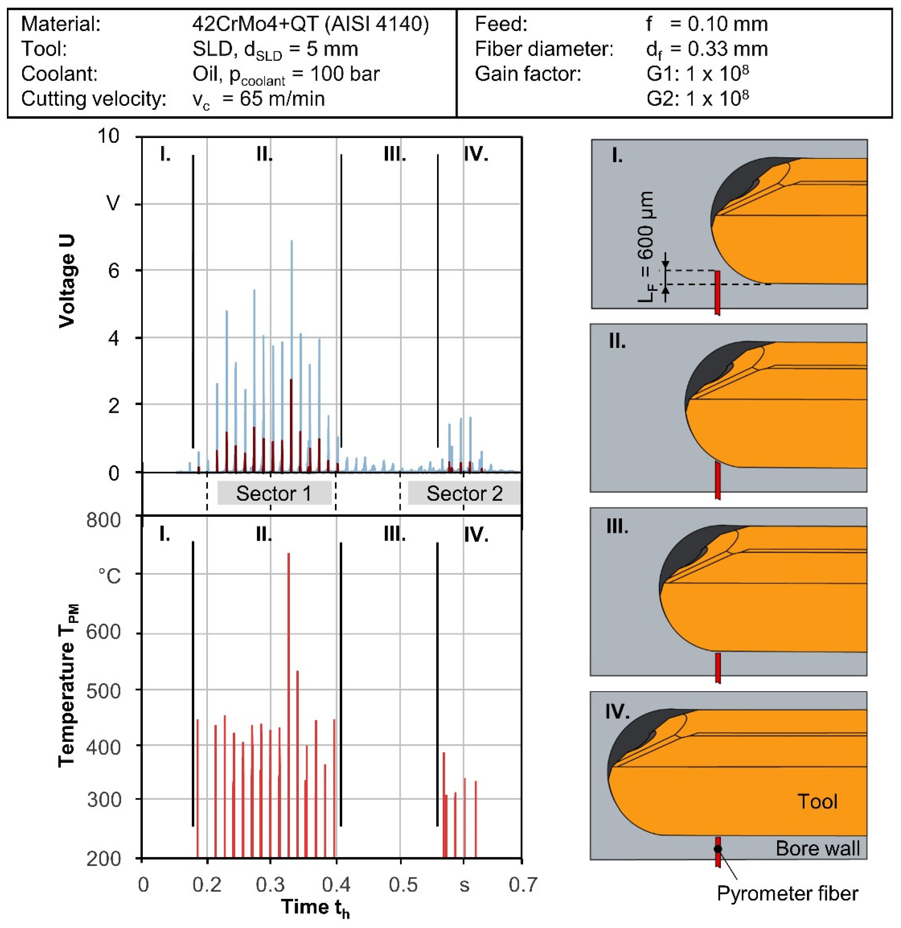
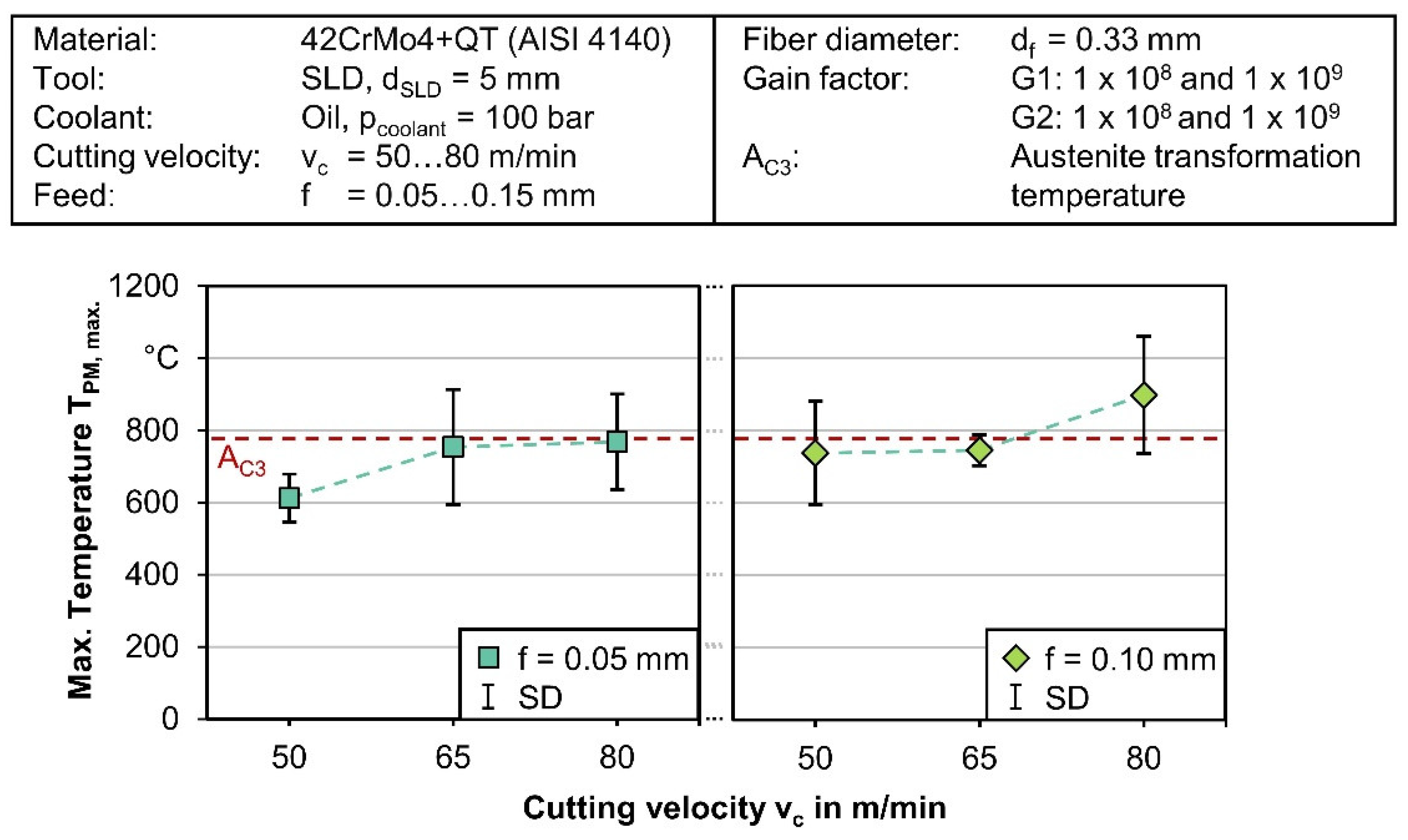
3.2. Pyrometric In-Process Temperature Measurement

A plot of the temperature measurement by means of pyrometry is shown in Figure 6. For the evaluation, the measured voltage signals were converted into temperature values. Considering the contact conditions between tool and pyrometry fiber, the measurement signal can be divided into four phases in time progression, which are sketched in Figure 6.
Phase I shows the pyrometry fiber protruding into the bore path before contact with the tool. In phase II, the fiber is cut with each contact with the cutting edge of the drill, whereupon a measurement of the emitted thermal radiation in the cutting zone is taken. Each peak in the temperature plot represents one revolution of the tool. In this phase, the highest temperatures are measured. Phase III describes the transition between the arc shaped outer cutting edge of the tool and the beginning minor cutting edge and the guide pads of the drill head, which are passing the pyrometric fiber. At this position of the drill head, the thermal load onto the bore surface decreases. Due to the implementation of threshold filters of Umin. = 0.1 V, which is higher than the measured voltage signals at this point, no temperature is output. In phase 4, the guide pads pass the pyrometer fiber with each revolution of the drill, showing an increase in the measured temperatures again. Of particular relevance in the evaluation of the results is the distinction between sector 1, where the heat results mainly from the cutting energy, and the sector 2, where the heat results mainly from the contact between the guide pads and the bore wall. This interpretation can provide an understanding of the effects in the single-lip drilling process that are decisive for the thermally induced alternations in the bores surface layers. In all pyrometric measurements, the temperatures measured at the tool cutting edge were significantly above the temperatures measured at the guide pads. This leads to the conclusion that the highest thermal load is generated from the cutting energy at the tool cutting edge. For the further analysis of the thermal impact of the cutting values on the bore wall, the maximum temperatures occurring in the area of the tool cutting edge were evaluated.
Figure 7 shows the results of the evaluation of the maximum temperatures for a range of cutting velocities between vc = 50, 65, and 80 m/min and for the feed rates of f = 0.05 mm and 0.10 mm. In these graphs, an increasing process temperature can be observed both with increasing cutting velocity and with increasing the feed rate. The temperatures range from TPM, max. = 612 °C for the cutting value combination with the lowest material removal rate vc = 50 m/min and f = 0.05 mm, and a temperature of TPM, max. = 897 °C for the cutting value combination vc = 80 m/min and f = 0.10 mm. For the cutting velocities vc = 50 m/min and vc = 80 m/min, the temperature measured in the cutting zone increases significantly with an increase in the feed rate from f = 0.05 to f = 0.10 mm. In case of the cutting velocity vc = 65 m/min, the temperatures are at a similar level of TPM, max. = 754 °C (f = 0.05 mm) and TPM, max. = 745 °C (f = 0.10 mm) for both feed rates. For the combination with the highest material removal rate vc = 80 m/min and f = 0.1 mm the temperatures lay in a range significantly above the austenitizing temperature. In case of the other cutting parameter combinations, the standard deviation of the measured temperature peaks reaches temperatures above AC3 Temperature for AISI 4140 steel. The AC3 ≈ 735 °C and AC3 ≈ 780 °C (start and end temperature of the austenite transformation) can be seen as an indicator for reaching a critical cutting parameter range. Nevertheless, especially in machining processes the high heating rates influence the phase transformation process and can increase the Ac1 and Ac3 temperatures [14].

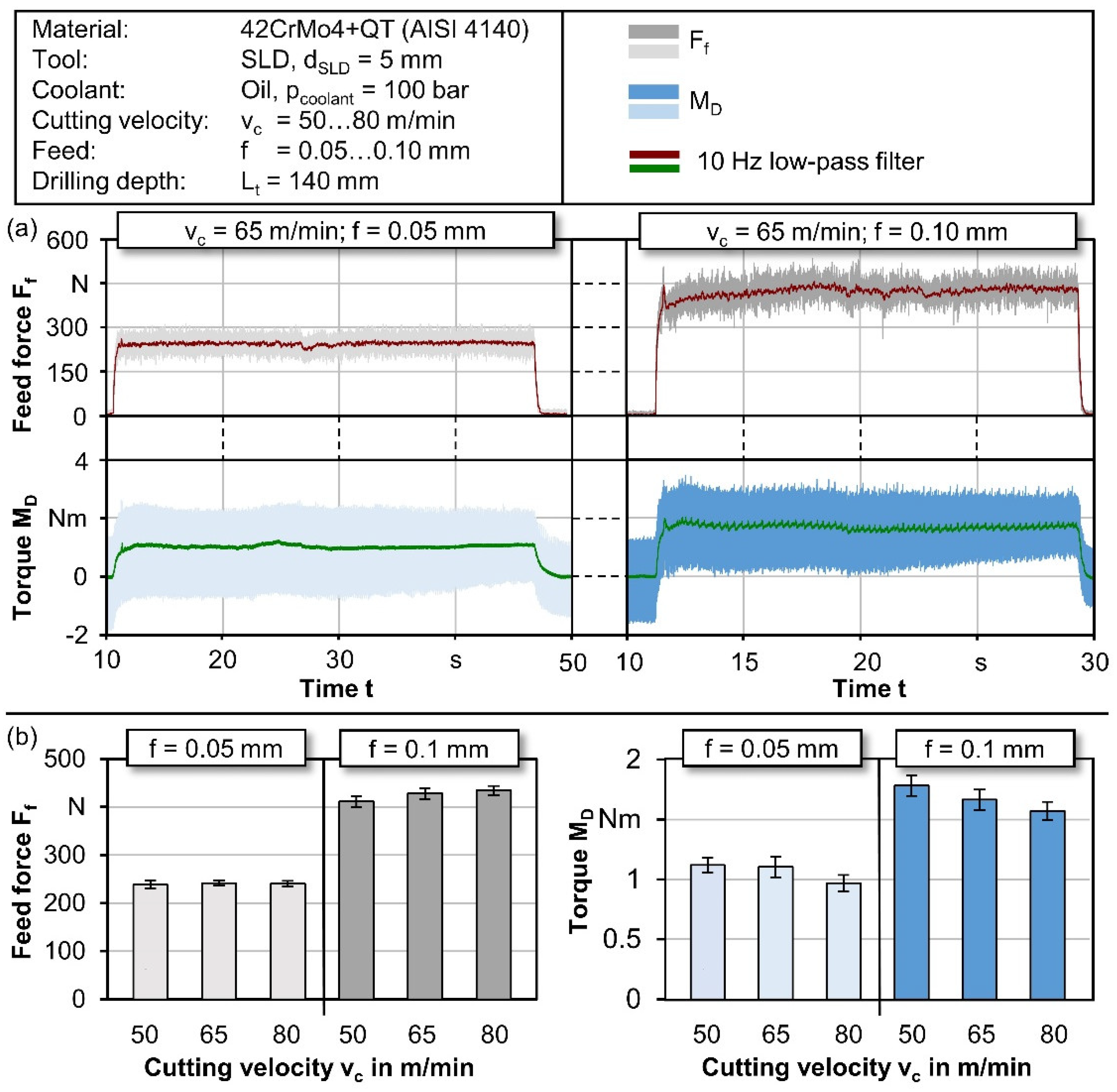
3.3. Analysis of the Mechanical Load on the Bores’ Surface

To evaluate the mechanical loads, the measured feed force and drilling torque resulting from shear and deformation processes as well as friction during the drilling operation are presented. While Figure 8a shows an exemplary plot of the force and torque measurement for a cutting velocity of vc = 65 m/min, Figure 8b shows an evaluation of the mean values including the standard deviation from six measurements per cutting parameter combination.
The results show that the feed forces as well as the drilling torque increase significantly with a doubling of the feed per tool revolution from f = 0.05 to f = 0.10 mm. Due to the accompanying doubled undeformed chip thickness, the feed force Ff = 237 N increases to Ff = 411 N by 73% for the low cutting velocity of vc = 50 m/min. In case of the high cutting velocity of vc = 80 m/min, the feed force increases from Ff = 240 N to Ff = 434 N, by 81% for the same increase in feed rate. In addition to the feed force, the values of the drilling torque MD are presented. The drilling torque is essentially a composition of the cutting force and the frictional and forming forces acting on the guide pads, whereby the cutting force accounts for the largest share of the drilling torque. The measured values also show an increase (of 52–62%) in the drilling torque that comes along with the increase in the undeformed chip thickness. It is noticeable that the measured drilling torque decreases significantly with increasing cutting velocity. For the feed rate of f = 0.05 mm, the drilling torque decreases from MD = 1.12 Nm to MD = 0.97 Nm, which corresponds to a reduction of 13%. For the higher feed rate f = 0.10 mm, the drilling torque decreases by 12% from MD = 1.78 Nm to MD = 1.57 Nm for the same increase in cutting velocity. This reduction in the drilling torque measured with an increase in the cutting velocity can be related to the thermal softening of the workpiece material. The amount of effective active power Pe introduced into the workpiece material increases for higher cutting velocities, which leads to an increase in the temperature in the cutting zone [15]. In the discussed temperature measurements, the bore marginal zone (Figure 5) and the contact zone between tool and workpiece (Figure 7), this increase in temperatures with increasing cutting velocity during single-lip drilling could be verified. The standard deviation in the force and torque diagrams can be regarded as an indicator of the axial and torsional vibrations occurring during the process. For the feed force, the standard deviation values are in a range of 2–4%, for the drilling torque, in a range of 5–7%. From these values it can be concluded that the torsional vibrations are slightly stronger than the axial vibrations occurring in the feed direction. Torsional vibrations are promoted by a relatively large l/D ratio of the tools. However, an influence of the cutting values on the standard deviation is not evident in the measured values.

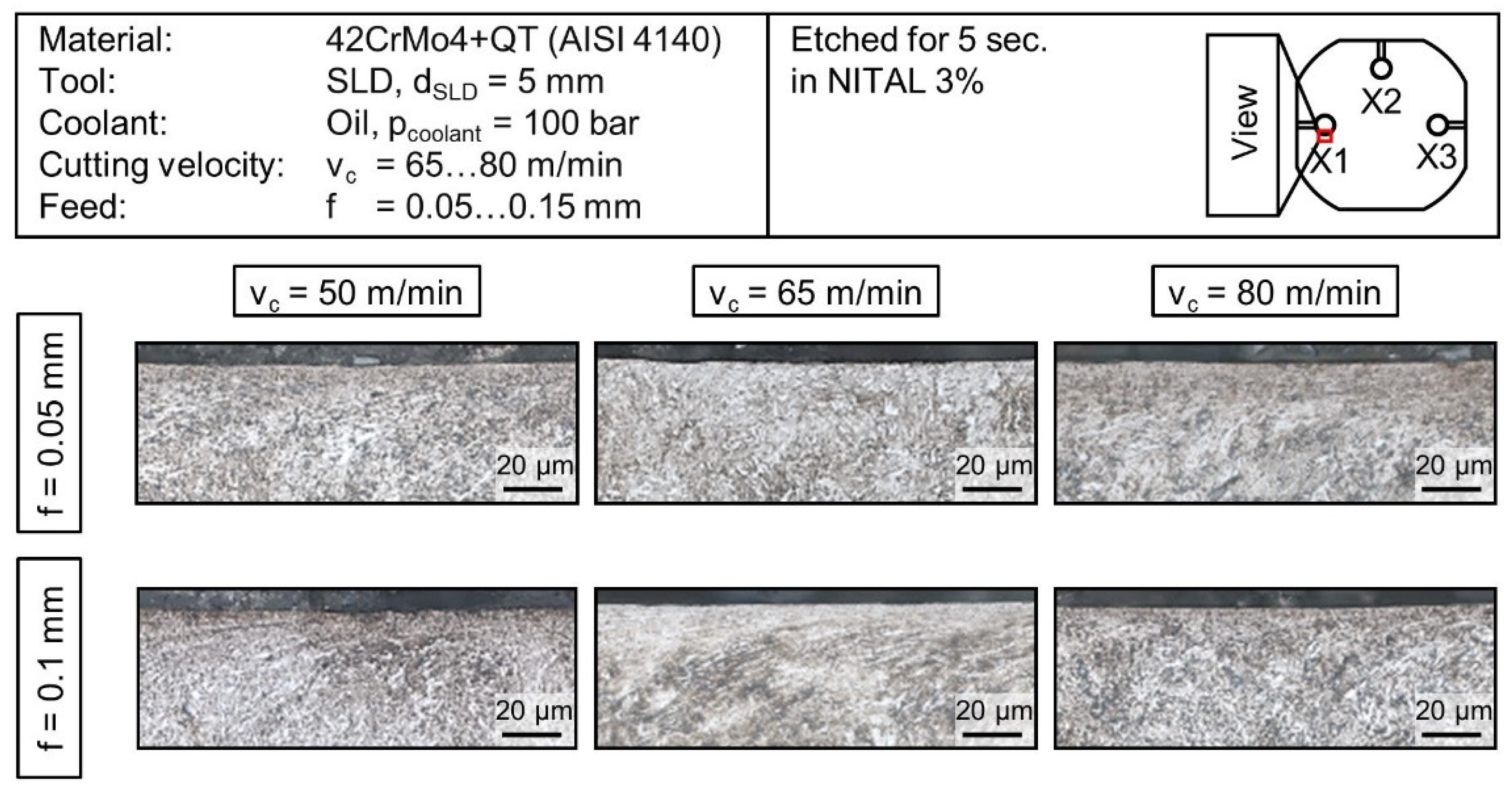
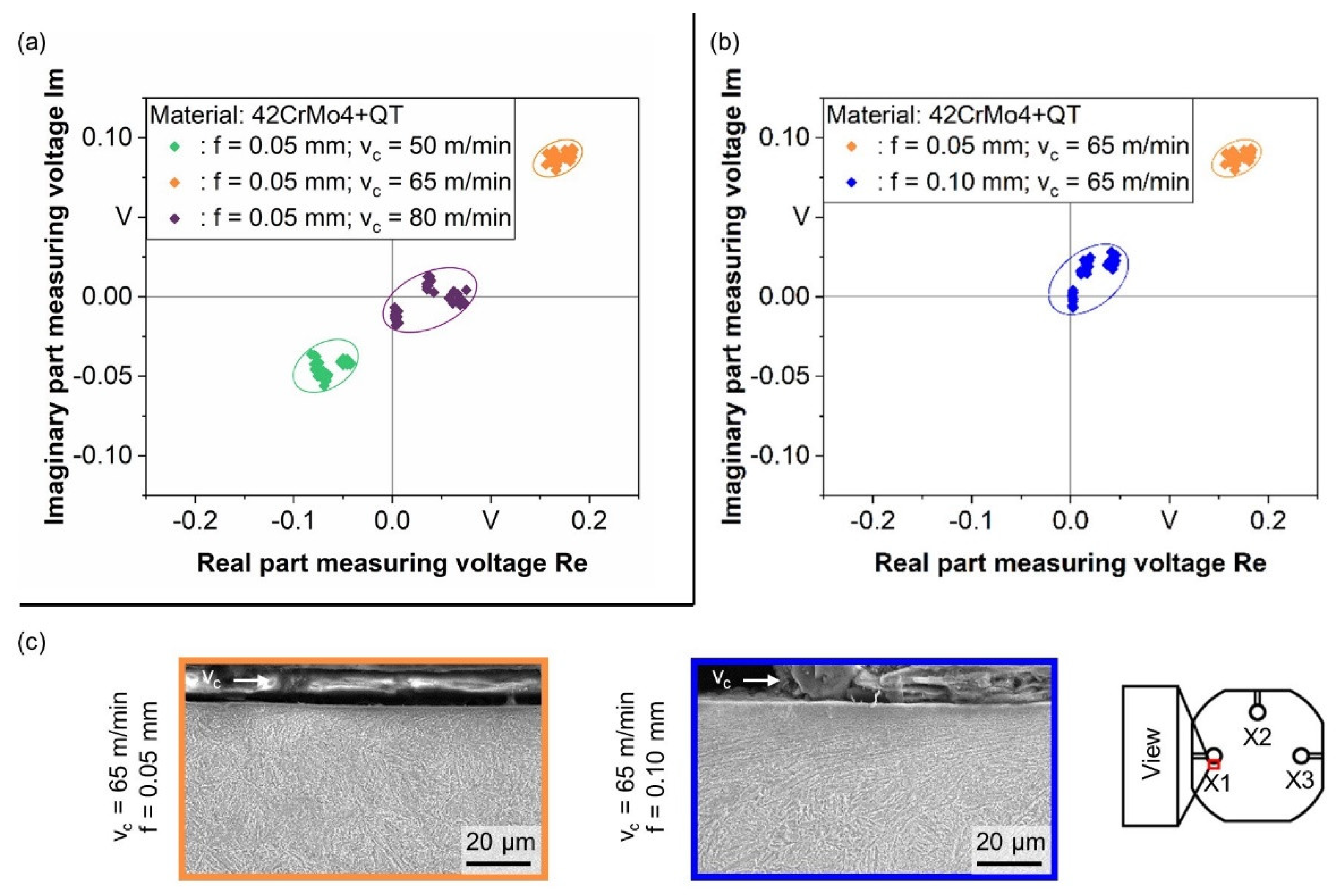
3.4. Surface Integrity Characterization

Cross-sections of the deep-drilled specimens show the thermomechanical influence of the single-lip deep hole drilling process on the microstructure of the bores’ subsurface (Figure 9). The micrographs reveal deformation of the microstructure in direction of the cut for all cutting parameter combinations. However, the microstructure deformation and refinement are more pronounced at the higher feed rate of f = 0.10 mm, which is related to the higher process forces acting on the bores’ surface and subsurface. At the cutting velocity of vc = 80 m/min, the microstructure deformation is slightly less prominent than at the lower cutting velocity for the given feed rate. No thermally induced WEL could be observed at the circumference of the bore in any of the cross sections, although the pyrometrically measured temperatures reached values above the AC3 temperature, especially for the highest feed/cutting speed combination. Investigation on the phase transformation process for machining processes suggest, that the austenitization is not only dependent on the temperature, but also on the heating rate [14]. It is also possible that the WEL in the bore wall occurs only partially along in the microstructure along the bore wall, which will be analyzed in more detail in further investigations.
The non-destructive characterization of the surface condition was carried out by means of eddy-current measurements. Figure 10a shows eddy-current measurements of bores drilled with varying cutting velocities, Figure 10b shows results of bores drilled with varying feed rate by otherwise constant parameters.
A clear separation between each individual varied parameter can be found. Whereas a classification between simultaneous changed cutting velocity and feed is challenging. Previously conducted investigations published in [3] allow the assumption that the correlation is caused by changes in the subsurface microstructure of the bores wall. With regard to the micrographs in Figure 10c, which match the cutting parameter combinations for the eddy-current analysis in Figure 10b, this assumption can be substantiated, that the eddy-current values represent different states of the microstructure condition. For the higher feed rate, the microstructure shows a stronger deformation resulting from the mechanical load of the drilling process. However, the findings from the eddy-current analysis cannot be clearly led back to the thermal influence of the drilling process.

4. Conclusions and Outlook

The objective of this paper is to assess the thermomechanical impact of the single-lip deep hole drilling process on the surface integrity of the bore. In particular the temperature measurement in the bore wall as well as in the contact area between tool and bore surface were in focus of the investigations. A combination of thermoelectric and pyrometric temperature measurement was applied to enable an in-process temperature measurement of the thermal loads acting on the bore surface and subsurface. These measurements, in combination with the determination of the mechanical loads occurring during the drilling process, provide information about the effects causing a modification of the bores’ subsurface microstructure. The relationships between the thermomechanical impact onto the surface layers and the subsurface microstructure were revealed in cross sectional micrographs. In addition, the eddy-current assessment was applied as a non-destructive method to characterize the produced surface integrity under varying cutting conditions.
The findings obtained can be summarized as follows:
  • The temperature measurement using thermocouples enables the determination of temperatures in the bores’ subsurface. Both with a higher the feed rate and with an increase in the cutting velocity, the temperatures in the bore wall increased. However, the thermoelectric measurement does not allow a direct assessment of the temperatures prevailing in the tool/workpiece contact zone.
  • The temperature measurement by means of ratio pyrometry allows the in-process temperature measurement directly at the tool’s cutting edge and at the guide pads with a frequency of fp = 7 kHz. With variation of the cutting values, an increase of the temperatures in the tool/workpiece contact zone was found, both with an increase of the feed rate from f = 0.05 mm to f = 0.10 mm and with an increase of the cutting velocity in a range from vc = 50–80 m/min. On average, the measured temperature peaks reached up to TPM, max. = 897 °C for the cutting value combination with the highest feed rate and cutting velocity (vc = 80 m/min; f = 0.10 mm).
  • The analysis of the mechanical tool load reveals a reduction of the drilling torque with an increase of the cutting velocity. Considering the development of the drilling torque in connection with the temperature measurement results, it appears that a thermally induced softening of the workpiece material occurs at high cutting velocity. This effect has a major impact on the cutting forces, which are reflected in particular in the drilling torque. The objective of inducing a certain plastic deformation into the bore’ subsurface by applying high mechanical loads to the bore wall during single-lip deep hole drilling can be counteracted by effects such as thermal softening.
  • The temperature peaks also reach a range above the austenitizing temperature of the workpiece material at higher cutting velocities, potentially increasing the risk of partial WEL formation. In the areas of the bore that could be investigated by microstructural analysis, no WEL formation was found. Nevertheless, differences in the plastic deformation of the microstructure near the edge zone could be detected for the varied cutting value combinations and associated mechanical loads on the bores’ surface layer.
  • Using the non-destructive method of eddy-current analysis, the changes in the generated subsurface microstructure conditions could be detected. However, establishing the correlation of the results to thermal and mechanical loads during the drilling process is still challenging. Classification of the surface integrity by eddy-current measurement is to be further explored to estimate damage states and the associated remaining life of components.
In further investigations, the scope of the experiments is expanded to include alternate cooling lubricant variants, such as minimum quantity lubrication (MQL) and water based emulsion. Thereby, a holistic consideration of the thermomechanical effects on the bore wall and the associated surface integrity are to be enabled. This data will be used for a numeric modelling of the interactions between the process parameters during the single-lip deep hole drilling and the produced surface integrity properties that are decisive for the fatigue strength of the machined specimens.

Author Contributions

Conceptualization, J.N.; Data curation, J.N. and N.B.; Investigation, N.B. and P.V.; Methodology, J.N.; Project administration, F.W. and D.B.; Visualization, J.N., N.B. and P.V.; Writing—original draft, J.N.; Writing—review & editing, N.B., P.V., F.W. and D.B. All authors have read and agreed to the published version of the manuscript.

Funding

The project “Investigations on the influence of machining and sulfur content on the fatigue strength of the quenched and tempered steel 42CrMo4 + QT” was funded by the Deutsche Forschungsgemeinschaft (German Research Foundation, DFG)—project number 320296624.

Institutional Review Board Statement

Not applicable.

Informed Consent Statement

Not applicable.

Data Availability Statement

Not applicable.

Acknowledgments

We acknowledge financial support by Deutsche Forschungsgemeinschaft and Technische Universität Dortmund/TU Dortmund University within the funding programme Open Access Publishing.

Conflicts of Interest

The authors declare no conflict of interest.

References

  1. Koster, W.P.; Field, M.; Kahles, J.F.; Fritz, L.J.; Gatto, L.R. Surface integrity of machined structural components. In Technical Report AFML-TR-70-11; Metcut Research Associates Inc.: Cincinnati, OH, USA, 1970. [Google Scholar]
  2. Novovic, D.; Dewes, R.C.; Aspinwall, D.K.; Voice, W.; Bowen, P. The effect of machined topography and integrity on fatigue life. Int. J. Mach. Tools Manuf. 2004, 44, 125–134. [Google Scholar] [CrossRef]
  3. Nickel, J.; Baak, N.; Biermann, D.; Walther, F. Influence of the deep hole drilling process and sulphur content on the fatigue strength of AISI 4140 steel components. Procedia CIRP 2018, 71, 209–214. [Google Scholar] [CrossRef]
  4. Nickel, J.; Baak, N.; Walther, F.; Biermann, D. Influence of the feed rate in the single-lip deep hole drilling process on the surface integrity of steel components. In Advanced Surface Enhancement; Itoh, S., Shukla, S., Eds.; Springer: Singapore, 2020; pp. 198–212. [Google Scholar]
  5. Baak, N.; Schaldach, F.; Nickel, J.; Biermann, D.; Walther, F. Barkhausen noise assessment of the surface conditions due to deep hole drilling and their influence on the fatigue behaviour of AISI 4140. Metals 2018, 8, 720. [Google Scholar] [CrossRef] [Green Version]
  6. Basara, A.; Nicolas, A.; Schlücker, E. Influence of the pressure holding time on strain generation in fuel injection lines. Int. J. Press. Vessel. Pip. 2011, 88, 132–137. [Google Scholar] [CrossRef]
  7. Biermann, D.; Bleicher, F.; Heisel, U.; Klocke, F.; Möhring, H.-C.; Shih, A. Deep hole drilling. CIRP Ann. 2018, 67, 673–694. [Google Scholar] [CrossRef]
  8. Griffiths, B. Manufacturing Surface Technology: Surface Integrity & Functional Performance, 1st ed.; Penton Press: London, UK, 2001. [Google Scholar]
  9. Pan, R.; Ren, R.; Chen, C.; Zhao, X. The microstructure analysis of white etching layer on treads of rails. Eng. Fail. Anal. 2017, 82, 39–46. [Google Scholar] [CrossRef]
  10. Radaj, D.; Vormwald, M. Ermüdungsfestigkeit: Grundlagen für Ingenieure, 3rd ed.; Springer: Berlin/Heidelberg, Germany, 2007. [Google Scholar]
  11. Beno, T.; Hulling, U. Measurement of cutting edge temperature in drilling. CIRP Ann. 2012, 3, 531–536. [Google Scholar] [CrossRef] [Green Version]
  12. Bücker, M.; Oezkaya, E.; Strodick, S.; Biermann, D. A thermomechanical analysis leading to a novel flank face design providing longer tool lives for tools used in the drilling of Inconel 718. Int. J. Adv. Manuf. Technol. 2019, 102, 2977–2992. [Google Scholar]
  13. Michna, J. Numerische und experimentelle Untersuchung zerspanungsbedingter Gefügeumwandlungen und Modellierung des thermo-mechanischen Lastkollektivs beim Bohren von 42CrMo4. Ph.D. Thesis, Karlsruher Institut für Technologie, Karlsruhe, Germany, 2014. [Google Scholar]
  14. Mondelin, A.; Rech, J.; Feulvarch, E.; Coret, M. Characterisation of surface martensite-austenite transformation during finish turning of an AISI S15500 stainless steel. Int. J. Mach. Mach. Mater. 2014, 15, 101–121. [Google Scholar] [CrossRef] [Green Version]
  15. Biermann, D.; Iovkov, I.; Blum, H.; Rademacher, A.; Taebi, K.; Suttmeier, F.T.; Klein, N. Thermal aspects in deep hole drilling of aluminium cast alloy using twist drills and MQL. Procedia CIRP 2012, 3, 245–250. [Google Scholar] [CrossRef] [Green Version]
Figure 1. Tool properties and geometry.
Jmmp 05 00120 g001
Figure 2. Details of the sample preparation with cross-bores for applying thermocouples and a pyrometer fiber.
Jmmp 05 00120 g002
Figure 3. Sketch of the experimental setup including temperature and force measurement sensors.
Jmmp 05 00120 g003
Figure 4. Eddy-current testing device (a); eddy-current sensor on the inside of a specimen (b).
Jmmp 05 00120 g004
Figure 5. Average maximum temperatures measured with TC for different cutting velocities and feed rates.
Jmmp 05 00120 g005
Figure 6. Exemplary voltage and temperature measurement at different tool cutting-edge positions.
Jmmp 05 00120 g006
Figure 7. Maximum temperatures TPM, max. for a varying cutting velocities vc and feed rates f.
Jmmp 05 00120 g007
Figure 8. Exemplary force and torque measurement for the single-lip deep hole drilling process (a); Average feed force Ff and torque MD for different cutting velocities and feed rates (b).
Jmmp 05 00120 g008
Figure 9. Micrographs of the bores’ subsurface microstructure for different cutting velocities and feed rates.
Jmmp 05 00120 g009
Figure 10. Results of eddy-current measurement at bores drilled with different cutting velocities (a) and different feed rates (b); SEM microstructure analysis of the bores’ subsurface (c).
Jmmp 05 00120 g010
Table 1. Chemical composition of the workpiece material AISI 4140 (wt %).
CSiMnPSCrMoFe
0.410.180.850.0110.0111.010.18bal.
Publisher’s Note: MDPI stays neutral with regard to jurisdictional claims in published maps and institutional affiliations.

