1. Introduction
Surface finishing processes as hard turning and grinding determine the surface integrity of machined parts, e.g., surface roughness, residual stresses, hardening and microstructure, which can be of decisive importance for its functional performance [
1,
2,
3,
4]. Surface integrity represents the scientific field in which the correlations between surface characteristics and the part’s mechanical properties are analyzed. Surface engineering also covers manufacturing processes and thus addresses the generation of surface and subsurface states. In this discipline, the process parameters are chosen in order to reach specific part properties. Despite in-depth knowledge of many considered processes, the robust generation of surface states remains challenging due to material batch variations, tool wear and other disturbances. This motivates the measurement of the desired surface characteristics in-process directly or indirectly and the continuous control of its parameters in a closed-loop feedback. In
Figure 1, the generic scheme of a surface-focused process control is depicted. Through the realization of this concept, new possibilities may arise for the robust generation of surface characteristics, also in industrial practice. This general approach shall be called surface conditioning.
The in-line measurement of surface layer states such as grain size, hardness and residual stresses constitutes a major challenge, as many of those usually require destructive testing. Considering industrial applications, the measurements should be non-destructive and conducted in-line. Some sensors must run in the process environment, which may contain chips and cooling fluids. To meet these demands, innovative sensors and techniques are to be developed, which often indirectly measure surface states and require a careful calibration. Those approaches rely on the generation and implementation of complex models and are thus called soft sensors. This term and the complete nomenclature of surface conditioning is specified in a glossary [
5], which was also harmonized with the terms in [
6]. Those works are closely connected to the Collaborative Research Centers 136, 926 and the Priority Program 2086 of the Deutsche Forschungsgemeinschaft (DFG).
Soft sensors and their models play a decisive role in the conditioning of surface integrity. This also applies to process models, which allow to appropriately adjust process parameters when the risk of harmful surface characteristics is detected. Consequently, surface conditioning covers and relies on the findings of surface integrity and surface engineering. The subsequent section reviews fundamental aspects and recent developments of surface conditioning in cutting and grinding.
2. Causes and Modification of Surface Layer States
Cutting and abrasive processes modify the surface integrity of the workpiece by a combination of mechanical and thermal loads [
7,
8,
9,
10,
11]. The combined load collective is influenced by the process parameters, e.g., a higher cutting velocity leads to increased process temperatures, while the process forces maintain or decrease due to thermal softening. In contrast to the cutting velocity, the tool wear increases the process forces and thus the mechanical surface load, while increasing the process temperatures by frictional heat. Other dependencies are process-specific and must be analyzed individually. The surface modifications, which are caused by the thermomechanical loads, can be broadly classified into topography (roughness and surface microdefects), microstructure (phase composition, grain size, grain structure and various lattice distortions including work hardening or changes of hardness) and residual stress state. The topography of a surface is usually determined by the process kinematics and the tool geometry, e.g., by the feed and the tool nose radius within turning. Here, it must be considered that tool wear also changes the tool geometry.
Microstructural surface modifications are caused by a variety of physical mechanisms [
12]. The effects of process parameters are thus complex and must be examined in detail for different types of surface modification. The phase composition of a metal is significantly determined by the chemical composition, the present temperature, and the temperature history. High temperatures in pearlitic–ferritic steels may generate an austenitic microstructure and a subsequent rapid cooling a martensite. This untempered martensite is detrimental, as the brittle surface is prone to crack growth. Such phenomena are often seen in turning, drilling and grinding of steels. The crucial factors in this context are the surface layer temperature, the heating rate and the duration above the austenitization temperature. Considering machining parameters, a high cutting velocity leads to high thermal gradients, while the tool-workpiece contact length increases the heating time. Due to the high heat conduction and thus the self-cooling of metals, an austenitic microstructure is usually cooled fast enough to form martensite.
In [
13], BTA deep hole drilling of AISI 4140 QT tempered at T
temp = 640 °C was conducted. Depending on the cutting parameters, white surface layers were observed in micrographs of the drilled specimen, see
Figure 2a. The white layers vanished in an additional annealing step, which underlines its temperature dependency [
14].
Figure 2b shows that the microhardness in the white layer of a specimen at depths of d
surf = 5 µm under the surface reaches more than 900 HV0.01, which clearly indicates an austenitic–martensitic phase transformation. The probability of white layer formation within the given parameter field increases with both the cutting velocity and the feed. Regarding the white layer thickness, the values vary between t
WEL = 2–12 µm. When producing highly loaded parts those brittle layers are to be avoided. This requires lower thermal loads, e.g., lower cutting velocities. One of the strategies for reducing these loads is the discontinuous cutting as presented in [
15], where a discontinuous process strategy for drilling Inconel is evaluated in terms of microstructure and microhardness on the surface layer.
Contrary to pearlitic–ferritic steels, retained austenite of TRIP (transformation-induced plasticity) steels is intentionally transformed into martensite by mechanical loads, i.e., stresses and strains. This allows to locally strengthen workpieces against higher loads. Machining those steels under the right conditions can lead to components with a suitable hardened surface layer and ductile core, which are preferred in many applications. When realized in the final cutting step, this leads to short and cost-efficient process chains. In [
16] the effect of process parameters on the deformation-induced martensitic transformation was analyzed during cryogenic turning.
Figure 3 illustrates that the phase transformation was promoted by a low machining temperature (a) as well as by a high feed rate (b). Cryogenic precooling of the workpiece is required to promote the martensitic transformation, which lowers the stacking fault energy of the alloy [
17]. Furthermore, the initial local grain orientation of the workpiece material influenced the amount of transformed martensite. Machining of pretextured material was proposed for solving this issue. The correlation of the martensite content in the surface layer and the third harmonic amplitude in eddy current testing (3rd HA) will be addressed in
Section 3. The examples show that some surface layer transformations are to be avoided, while others are beneficial.
Plastic deformation of metals increases the dislocation density, and thereby causes work or strain hardening [
16]. The driving forces are mechanical surface loads. A surface layer hardened this way is not necessarily detrimental, but it depends on the application, whether a slightly hardened surface is desired. If the dislocation density in a metal exceeds a certain level, dynamic recovery and dynamic recrystallization occur. The main driving forces are high strains, stresses and hence mechanical loads. The hardness of recrystallized surfaces is increased due to the Hall–Petch effect, yet they are not as brittle as martensitic phase-transformed layers, and the fine-grained structure reduces crack growth. Thus, nanocrystalline surface layers are occasionally generated during cryogenic cutting [
17,
18]. Cryogenic cooling should avoid possible phase transformations by low process temperatures, while high process forces should trigger the dynamic recrystallization. Grains smaller in size than the wavelength of light cannot be resolved in optical microscopes [
19,
20,
21,
22,
23]. Consequently, nanocrystalline layers appear white and are commonly referred to as white layers. These structures may also contain untempered martensitic phases or tensile residual stresses. In general, however, it cannot be stated that white layers always have a detrimental effect, rather, the underlying physical characteristics must be taken into account [
24].
When turning AISI 4140 QT, different mechanisms such as work hardening, dynamic recrystallization and phase transformations may occur, depending on the tempering treatment, the process parameters and the tool wear [
25]. It is not the existence of a white layer, but the microhardness which must be taken as the indicator for thermally transformed surface layers. In
Figure 4, hardness profiles of AISI 4140 QT tempered at 450 °C and machined with the tool wear VB = 0.3 mm are presented. The specimen with lower cutting velocity or lower feed exhibits a significant increase in surface hardness. This may be explained by grain refinement and work hardening and is thus not considered critical for the surface integrity. However, this is the case for the specimen machined with the highest cutting parameters, where 600 HV marks the threshold for a martensitic microstructure. An equivalent measure for surface modification is the hardness increase ΔHV, which is depicted in the top right diagram. The implications of such a threshold for process modelling will be discussed in
Section 4.
Machining processes are known for the generation of residual stresses which are superimposed by the operational loads of a component. In contrast to tensile surface stresses, which open existing cracks, compressive surface stresses close cracks. This leads to a decrease of the stress amplitude in fatigue tests for a given number of loading cycles when higher mean stresses are applied. The phenomenon was comprehensively reviewed by Sasmantatras et al. [
26] and confirmed for AISI 4340 QT. Thermal loads generally cause surface tensile stresses, while mechanical loads lead to surface compressive stresses [
27]. The combination of both load types in cutting and abrasive processes often leads to a hook-shaped stress-depth profile, where the minimum residual stresses are located in the subsurface. When examining the influence of turning process parameters, it can be observed that the feed, the tool nose radius and the tool wear significantly increase the axial surface residual stresses [
28,
29]. Furthermore, the cooling concept influences the thermomechanical load collective and the residual stresses after machining. Basten et al. [
30] analyzed different cooling concepts for turning AISI 52100, namely dry cutting, CO
2-snow, liquid nitrogen and a subzero metalworking fluid. The effects on the axial residual surface stresses are depicted in
Figure 5. Herein, Segments 1 and 2 indicate specimen segments measured at different axial positions. Compared to dry cutting, using cooling media generally leads to more compressive residual stresses. A systematic difference between Segments 1 and 2 cannot be observed. While LN2 cooling provided the lowest tool temperatures, residual stresses resulting from LN2 machining are the highest of the compared cooling concepts.
In [
31] the resulting surface topography was also analyzed. It is explained that in-process variations of the tool microgeometry or ploughing effects cause deviations of the surface topography. Scanning electron microscopy measurements show that process cooling with CO
2-snow or LN
2 causes more durable build up edges and consequently increases the surface roughness, while lower roughness values are achieved in dry cutting or with the subzero metalworking fluid, which is not as cold as the media mentioned before.
Considering surface modifications in general, it can be concluded that thermal workpiece loads may be detrimental and lead to thermal damage of the part. Mechanical loads often lead to desired modifications such as nanocrystalline surface layers or compressive stresses. This motivates the control of the thermomechanical loadings during cutting and abrasive machining. The presented examples show that those approaches are process- and workpiece material-specific and thus require an excellent knowledge of the physical mechanisms.
3. Measurement of Surface Layer States
The complex mechanisms and the existence of known and unknown disturbance variables impede the realization of surface control without feedback. The continuous measurement of the target surface characteristics with an adequate cycle time is thus required. Under this aspect, a direct integration of measurement technique into the process is preferred. The different options for integration are depicted in
Figure 6.
The short cycle times and the requirements of nondestructive testing are only fulfilled by specific, usually indirect measurement principles. Conventional principles of surface and subsurface measurements which do not meet these requirements are not reviewed in this context. However, they are usually required to validate measurements acquired by indirect principles.
Surface topography can generally be captured by tactile measurements. Disadvantages include long measure times and the need for slow relative velocities between the sensor and workpiece. Hence, on-machine integration of tactile measurements is hardly realized. Optical devices allow non-contact surface topography measurements. Examples are confocal light microscopes. Yet, these are hardly applied for on-machine measurements, as they require reproducible ambient light conditions as well as the absence of both, vibrations and films of metal working fluid on the workpiece. Attractive options include scatter light methods, which measure the surface topography. The necessary light source can be coherent or incoherent, leading to different characteristics. A coherent light source allows the identification of spatially resolved roughness information; however, the requirements for the ambient conditions and measurement evaluation are quite high. With an incoherent light source, the spatial information is lost, i.e., only mean roughness information is acquired, but the on-machine integration and evaluation are more convenient [
33]. In [
34], the control target value surface topography is to be monitored in-process by an angle resolved scattered light sensor, which is not influenced by machine vibrations. This sensor is combined with a pneumatic sensor, which deduces occurring tool wear by the measured distance between the tool holder and the machined surface. As an additional function, the pneumatic sensor should blow off cryogenic cooling media, which otherwise would impair the scattered light measurements. An interesting alternative to optical devices is the indirect measurement of the topography by micromagnetic principles. In [
35], for example, it was shown that the measured volt amplitude can be correlated to the surface roughness. This requires a material-specific determination of the measurement setpoint and a calibration of the eddy current sensor.
The measurement of microstructural and mechanical surface characteristics is usually expensive and time consuming. Typical examples include electron microscope measurements of the grain structure, x-ray diffraction analysis of residual stresses and full width at half maximum or electron backscatter diffraction measurements of the phase composition. Furthermore, these techniques require direct contact to the measurement spot, i.e., in-depth measurements are always destructive. The same applies for direct measurements of mechanical properties, e.g., hardness or tensile tests. Therefore, a seamless integration into manufacturing processes is almost impossible. In order to overcome the aforementioned challenges, the non-destructive, indirect measurement of mechanical and microstructural metal characteristics via micromagnetic testing has been established in manufacturing [
36]. Widely used measurement principles are harmonic analyses of the magnetic field strength, Barkhausen noise, multi-frequency eddy current analysis and incremental permeability. Each principle allows to acquire multiple electromagnetic parameters of a specimen, e.g., more than 40 parameters can be measured by the multiparametric microstructure and stress analyzer (3MA) of the Fraunhofer IZFP [
37]. A number of dependencies between micromagnetic and mechanical parameters have been proven. In steels, for example, the coercivity increases due to a smaller grain size or an increasing number of inclusions [
38]. This shows that mechanical hardening often results in magnetic hardening, yet a quantitative measurement of mechanical quantities always requires a sensor calibration. Furthermore, these dependencies are less explicit when multiple microstructural characteristics and residual stresses of a surface layer change, as it is usually the case in cutting and abrasive processes of metals. In this case, multiple magnetic parameters must be recognized during a calibration, which requires a sufficient number of test samples.
Schmidt et al. [
14] investigated the drilling of the quenched and tempered steel AISI 4140 QT. The Barkhausen amplitudes of drilled AISI 4140 QT specimens were increased by stress relief annealing. This was attributed to a relaxation of the compressive residual stresses, which were previously induced by machining. Strodick et al. [
38] proved that the maximum magnetic Barkhausen amplitude in subsurface zones of the bores of AISI 4140 QT was well correlated with the residual stresses caused by dynamic effects during the BTA drilling process. The specimen presented in
Figure 2 were also analyzed by Barkhausen measurements [
10]. The microhardness at a distance of d
surf = 5 µm from the bore surface reaches more than 900 HV0.01, while it is less than 400 HV0.01 in the bulk material. This indicates the existence of martensite within and close to white layers. Compared to specimens without white layers, the magnetic Barkhausen amplitude is lower. This might be explained by the occurrence of martensite in the surface layer as well as by the nanocrystalline grain structure of the white layer. These findings motivate the use of Barkhausen measurements for the controlled machining of white layer-free bores. The next steps for realizing process control are to gain a deeper understanding of the interactions between the cutting parameters and surface conditions in order to formulate a model, which allows adjusting process parameters before white layers occur.
Considering the turning of AISI 304, the effect of the feed rate and the initial workpiece temperature on the generation of martensite in the workpiece surface is depicted in
Figure 3. Additionally, the specimens were analyzed by eddy current measurements. The graphs in
Figure 3 demonstrate a high correlation of the third harmonic amplitude and the mean martensite content in the surface layer. Apparently, the ferromagnetic martensite generates higher harmonic amplitudes, in contrast to paramagnetic austenite. These findings motivate the use of eddy current testing for setting a desired fraction of martensite in process control. The required process parameters can be calculated by using a quantitative regression model for the martensite generation, published in [
39].
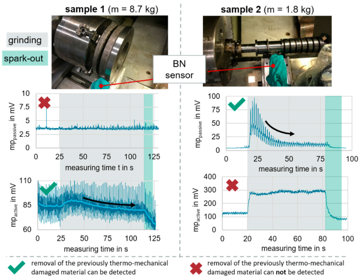
Micromagnetic testing is the state of the art for the post process detection of thermal damage on ground parts [
40]. Recent studies during grinding have further shown that the Barkhausen noise (BN) technique can be used in-process in two variants, the so-called active and passive Barkhausen noise measurement [
41]. Active refers to the conventional external excitation of a magnetic field, while passive refers to the measurement of Barkhausen noise without external magnetic excitation. This is explained by a process parameter-specific mechanical excitation of the workpiece.
Figure 7 compares signals resulting from active and passive measurements for different process conditions. It is argued that the lighter workpiece (sample 2) is prone to mechanical excitation by the grinding wheel. In this case the passive signal is significant, while the active one is saturated and thus insignificant. When grinding sample 1, the active signal is significant, while the passive one is not. Thus, the selective application of active and passive Barkhausen noise can help to identify surface characteristics under different machining conditions. Nevertheless, it remains challenging to reliably identify different levels of thermal workpiece damage, e.g., shift of residual stresses, light tempering, strong tempering and rehardening, due to the multiple mechanical and microstructural parameters, influencing the Barkhausen noise [
42]. Hence the measurements are to be complemented by process knowledge, which is derived from the model-based grinding burn limit of Malkin and allows to avoid visible tempering and rehardening in the surface and subsurface area of the workpiece [
43,
44]. Further steps are the fusion of Barkhausen noise with the model-based knowledge into a soft sensor, and finally the realization of a process control for non-circular and external circular grinding.
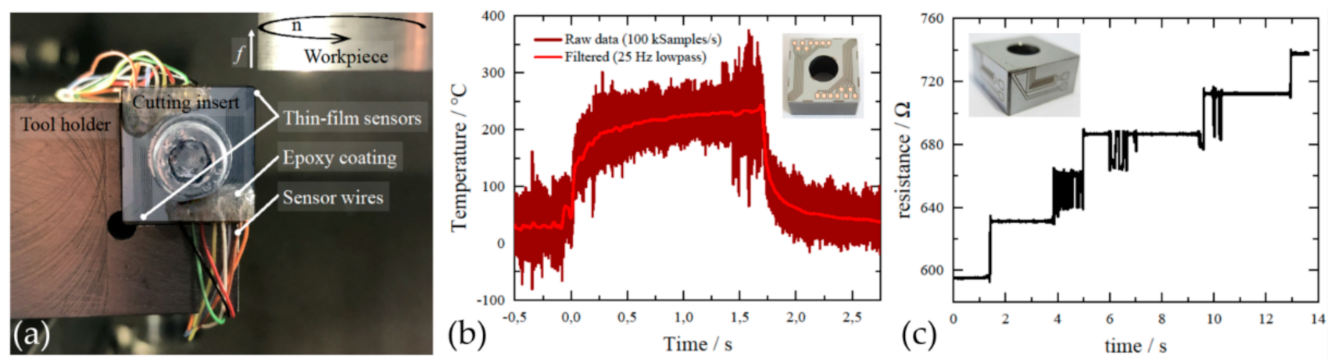
An alternative to the identification of surface characteristics based on micromagnetic properties is the monitoring of cutting process variables and the deduction of mechanical and microstructural characteristics by the means of process models. Suited process variables may include measures of the thermomechanical surface loads. González et al. [
45] presented an approach for obtaining the desired nanocrystalline surface layer thicknesses and thus microhardness profiles when turning AISI 4140. The concept is based on a soft sensor, which receives information about the chip-tool interface temperature and tool flank wear from thin film sensors integrated in the insert’s coating layers [
46]. The experimental setup with the in-tool-integrated thin film sensors is presented in
Figure 8a. Temperature sensors were applied on the insert rake face and electric conductor lines on the flank face. The destruction of those lines and the dependent resistance increase are thus a measure of the flank wear land width. Examples of the measurements are depicted in
Figure 8b,c, respectively. The thin film measurements are to be complemented with a database of the process in order to achieve the desired grain microstructure and thus the desired surface microhardness by adjusting the actuating variables v
c and f. The derivation of the database, which is realized by FE-simulations amongst others, is presented in
Section 4.
Schwär et al. [
47] presented an approach to predict the surface residual stresses of turned Ti-6Al-4V parts via acoustic emissions (AE). For this purpose, the process is monitored by signal processing of acoustic emission to identify the chip segmentation frequencies with the aim of establishing an empirical correlation with the residual stresses. The chip segmentation frequency was measured first off-line optically using a scanning microscope and calculating the compression ratio [
48], and in-line using the AE sensors. The results were used to calibrate and validate 2D and 3D FE simulations to predict chip segmentation and residual stresses under different cutting conditions, process parameters and tool wear states. As shown in
Figure 9a, structure-borne sensors and airborne sensors are mounted in the machine to measure the AE and to identify the segmentation frequency of the titanium chips. These chips present a saw-tooth shape due to periodic strain localization caused by the prevalence of thermal softening over strain hardening. Abrasive tool wear leads to an increase in the cutting-edge radius resulting, as expected, into a considerably increase of the passive forces, as shown in
Figure 9b. However, this change is not significant in the chip segmentation frequencies. They stay almost constant independently from the cutting wear, although the cutting energy of the process increases.
Figure 9c shows the measured residual stresses using different states of wear.
Mehner et al. [
49] presented an approach for predicting the grain size by resistance measurements with the four-point probe method. The concept was successfully tested for the grain-size identification of cold-rolled DC04 sheets; however, it was concluded that the underlying models must be further developed to account for turned workpieces with inhomogeneous grain-size distributions. Junge et al. [
50] presented a measurement system for the monitoring of surface-layer states during turning of the aluminum alloy EN AW-2017 by a tool-workpiece thermocouple (TWTC). In
Figure 10, respective results are depicted and compared to measurements using a conventional thermocouple (TC), embedded into the insert, and force-gauge measurements.
In
Figure 10b, a process without irregularities is depicted, which is reflected by the steady course of the process forces and temperatures. Regarding the process signals in
Figure 10c, a chip was pulled between the tool-flank face and the workpiece after approximately 1 s of measurement time. The irregularity is displayed by the process forces and the temperature measured by the tool-workpiece thermocouple, yet not by the embedded thermocouple. Thus, it is confirmed that the tool-workpiece thermocouple exhibits quick response times, while the conventional measurement is damped due to the heat capacity of the tool [
51]. As the average temperature at the interface of the tool and the workpiece is measured, the tool-workpiece thermocouple indicates a lower temperature for higher feeds than the embedded thermocouple (see
Figure 10c). Nevertheless, accurate measurements can be performed in particular for machining processes with a small cross-section of the undeformed chip (see
Figure 10b). Especially in finish machining of parts where the depth of cut and feed are usually lower, this method is suitable.
Figure 10d depicts a typical residual-stress depth profile after the process. The residual stress at the minimum was taken as the characteristic value. As shown in [
52], these values can generally be predicted based on measured forces and temperatures. In
Figure 10e, these predictions are compared to experimental values. Since the process anomaly impacts the surface-layer state significantly, the model equations are not valid for processes with irregularities. This emphasizes the need for detecting process irregularities. Further steps consist of extending the investigations to processes with cooling lubricant, worn tools and machining of the alloy EN AW-7075.
4. Modeling of Surface Layer States
Modeling plays a decisive role for surface conditioning. Generally, models of surface characteristics can be used in two fields. Firstly, soft sensors require models to measure topographical, microstructural or mechanical target values. This applies both for the indirect measurement via optical or magnetic sensors as well as for the deduction of surface properties from process variables, such as tool temperatures or acoustic emissions. Secondly, the knowledge of process sensitivities is necessary to estimate the controllability of a surface characteristic and to finally correct respective deviations by actuating variables. For a sufficient control response time, the models usually have to be evaluated within less than one second. This motivates the use of analytical equations for process modeling. The initial step of surface layer modeling is the selection of target variables and thus model outputs.
The first group of such models is based on experimental observations which are analytically described with simple mathematical functions.
Figure 4 provides an example showing microhardness profiles resulting from turning AISI 4140. A hardness increase between the depth 5 µm and 50 µm was chosen as the surface modification criterion. In order to demonstrate the controllability of the process, the effects of the actuating variables cutting velocity and feed and the disturbance variable tool wear were evaluated. This was realized by formulating a simple linear model,
The term δ (…) indicates additional model variables which were investigated in the course of the experiments, namely tempering temperature, depth of cut, tool nose radius and different cooling concepts. The subscripts “n” indicate that the input variables were normalized to the intervals considered in the cutting tests. Ordinary regression was employed to derive the coefficients given in
Table 1. The coefficient values confirm that an increase in hardness caused by tool wear may be compensated by reducing the cutting velocity or the feed. In a further step, more complex model functions will be derived by methods of system identification, e.g., stepwise regression.
The Finite Element Method (FEM) provides valuable insights to machining mechanisms and is thus used in the context of surface conditioning. A validated FE machining model of surface modifications considerably reduces the efforts for metallographic analyses. This motivates to identify the dependencies of the nanocrystalline surface layer thickness not only by experiments but also by FE simulations [
51].
Figure 11a shows 3D FE simulations of the microstructure evolution, grain recrystallization and nanocrystalline layer formation during the turning process.
Figure 11b illustrates how higher plowing forces caused by a greater relation between cutting edge radius and depth of cut lead to thicker refined microstructures.
Figure 11c shows subsurface grain refinement caused by the mechanical and thermal load combination obtained with different cutting speed and feed parameters. The disadvantage of FE simulations consists of long run times, which impede the direct use of FE models in machining controls. Hence, the generated data is to be condensed into machine learning models such as, decision trees or analytical equations which take the process parameters and characteristics as input and deliver the nanocrystalline surface thickness. The data reduction of the specimen microstructure to a scalar value is motivated by previous works [
17,
52,
53,
54]. Exemplary model inputs include the measurements of the tool wear VB and the rake face temperature presented in
Figure 8. Redundant input parameters are permitted in order to improve model uncertainty and to discover unexpected process states during machining.
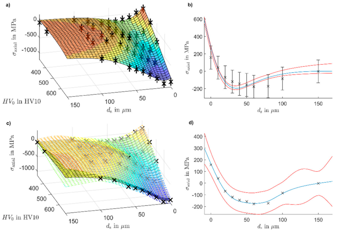
The mentioned approaches of modeling the microhardness increase and the nanocrystalline surface layer thickness operate with data reduction. However, residual stress profiles and other surface characteristics are in some cases hardly reduced to meaningful scalar values. This motivates the modeling of in-depth profiles of surface characteristics. The identification of such complex models may require machine learning approaches. Nevertheless, it is emphasized that the model evaluation must fulfill the real-time requirements of surface conditioning. Wittich et al. [
55] presented data-driven modeling of in-depth residual stress profiles resulting from the turning of AISI 6150 QT. A set of 328 data points of axial residual stresses was fitted by an ordinary linear regression over the input parameters depth, initial specimen hardness, feed and cutting velocity. Two variable selection methods were used to generate models: Stepwise Regression (SWR) and Least Absolute Shrinkage and Selection Operator (LASSO). In both cases, the adjusted coefficient of determination was R
2adj ≈ 0.7. The modeled polynomials were of fourth order, which indicates a high risk of oscillations that are not plausible in between sampling points. Takagi–Sugeno modeling was used as an alternative, local affine multi-model approach. Depending on the hyperparameters of the model, adjusted coefficients of determination R
2adj ≈ 0.9 were reached. In general, this proves that ordinary linear regression is not suited to model residual stresses profiles. In
Figure 12, based on the same data set, a Takagi–Sugeno model in (
a) and (
b) is compared to a Gaussian process regression model in (
c) and (
d).
Particular attention is paid to model prediction uncertainty. For the Gaussian process regression model, the confidence envelopes are automatically derived. In areas with low data density the envelopes widen, which can be seen e.g., in
Figure 12d for larger depths. However, when considering the physical mechanisms and empirical knowledge it is clear that residual stress profiles uncertainty at larger depths are definitely close to zero. This shows the deficits of data-driven approaches which are not complemented by mechanism knowledge. For the Takagi–Sugeno model, a bounded error parameter estimation was used. Depending on the error bounds, which can be chosen individually for each data point, feasible model parameter sets result. In bounded error estimation, no statistical assumptions are made about the error distribution. In GPR models, on the other hand, a normal distribution assumption is made, which is often not fulfilled in reality. Regarding the mean prediction and the measured values, both approaches are well suited for modeling residual stress profiles.


