Article

Modelling and Analysis of Topographic Surface Properties of Grinding Wheels

by
Praveen Sridhar
,
Daniel Mannherz
and
Kristin M. de Payrebrune
*
Institute for Computational Physics in Engineering, Technische Universität Kaiserslautern, D-67663 Kaiserslautern, Germany
*
Author to whom correspondence should be addressed.
These authors contributed equally to this work.
J. Manuf. Mater. Process. 2021, 5(4), 121; https://doi.org/10.3390/jmmp5040121
Submission received: 22 September 2021 / Revised: 29 October 2021 / Accepted: 31 October 2021 / Published: 10 November 2021

Abstract

:
Grinding is one of the effective manufacturing processes with which to produce highly accurate parts with an ultra-fine surface finish. The tool used to remove materials in grinding is called the grinding wheel. Abrasive grains made of extremely hard materials (alumina, silica, cubic boron nitride, and diamond) having a definite grit size but a random shape are bonded on the circumferential surface of the grinding wheel. The fabrication process is controlled so that the wheel exhibits a prescribed structure (in the scale of soft to hard). At the same time, the distribution of grains must follow a prescribed grade (in the scale of dense to open). After the fabrication, the wheel is dressed to make sure of its material removal effectiveness, which itself depends on the surface topography. The topography is quantified by the distribution and density of active abrasive grains located on the circumferential surface, the grains’ protrusion heights, and their pore volume ratio. The prediction of the surface topography mentioned above requires a model that considers the entire manufacturing process and the influences on the grinding wheel properties. This study fills this gap in modelling the grinding wheel by presenting a surface topography model and simulation framework for the effect of the grinding wheel fabrication process on the surface topography. The simulation results have been verified by conducting experiments. This study will thus help grinding wheel manufacturers in developing more effective grinding wheels.

1. Introduction to Grinding and Wheel Topography

Grinding is one of the basic and most important actions in the manufacturing process of various goods. It is especially important for achieving a good surface finish and quality of the products [1]. Grinding can be conducted in various ways but the most traditional and relevant way is by using a grinding wheel. Grinding wheels are fast turning wheels with an abrasive surface. Thus, a grinding wheel in contact with a workpiece will rub and wear away the material. The grinding process is aptly depicted in Figure 1, including the use of a coolant, which is used for cooling the grinding wheel/workpiece surface and removal of the grinding chips (workpiece chips and abrasive grains including bonds).
Two important components, abrasive grains and bonding material, make up any grinding wheel. First, the abrasive grains with the required size and the bonding material are carefully weighed and mixed thoroughly. A slight amount of wetting agent is added to moisten the mixture so that the bond particles adhere to the grains during the entire process. Then a proper amount of the mixture is evenly distributed in a steel mould of the desired wheel shape and compressed hydraulically. After particle packing and compressing of the mixture, the green blanks are carefully fired in the kiln with an accurate temperature control. This process causes the bond to melt and form a saturated case around each grain, converting the green blank into a hard, durable grinding tool. The modelling of vitrified wheels is conducted in this paper [3,4].
The modelling of grinding wheel topographies can be divided into two methods. Either existing grinding wheel topographies can be measured and digitised, or models can be generated synthetically. Using the second method, the topography is reproduced numerically with geometric bodies. This can be done in one, two, or three dimensions [5]. Past research works on grinding wheels not only evaluated grinding wheels based on empirical measurements but also with real images and simulations of the surface topography [6,7,8]. Hence, various surface topography models exist [5,9]. The surface topography aids evaluation of the measured values and thereby improves the understanding of the grinding process. Osa et al. [10] used the discrete element method to reproduce the granular structure of the grinding wheel. This study also employs the discrete element method (DEM) to reproduce the grinding wheel topography. Using the DEM, various grinding wheel topographies can be generated based on the average grain diameter, grain, and bond material parameters. The method can also be scaled to incorporate a high volume of particles to extend this simulation to generate a complete grinding wheel geometry. Chen et al. [11] generated a 3D grinding wheel topography with irregular grit forms and a random distribution of the grinding grits using the virtual grid method. Similarly Liu et al. [12] used octahedron grain shapes and a single-layer grain distribution based on the experimental analysis to obtain the grinding wheel topography. Liao et al. [13] numerically generated grinding wheel surfaces using the time series method. Zhang et al. [14] studied the 3D grinding wheel topography with image processing techniques. Gu et al. [15] developed a theoretical model of the grinding surface topography based on data models. Although previous simulations of grinding wheels and their topographies exist, only a few implemented a simulation of the individual manufacturing processes to manufacture a grinding wheel [1,16,17,18]. To obtain a better understanding of the grinding wheel surface and to obtain a more realistic visual image, the fabrication process needs to be included as part of a topographical simulation.
Furthermore, past research has only examined proportions in variations of bonding and abrasive materials [19] but did not examine compression and its effect on different output variables. Only one simulation specifically implemented the manufacturing process [16]. Although different output variables were analysed, it did not consider different compression levels even though the compression level is a relevant parameter. Therefore, compression levels in the manufacturing process and the possible effect on the grinding wheel properties need to be examined.
This study aims to provide a realistic simulation of the manufacturing process of a grinding wheel, starting with modelling of the raw material, compression, sintering, and dressing to obtain the final grinding surface. On considering the individual manufacturing steps in the production of the grinding wheel in the simulation, there is a possibility of improving and optimising the individual processes to obtain a grinding wheel with the desired characteristics. The obtained virtual grinding wheel model can also be used as digital twin and can be used in finite element method (FEM)-based simulations of a grinding process in the future. Hence, the simulation model can find scientific application in the field of digital manufacturing, digital twin modelling, and manufacturing process optimisation.
Additionally, the effect of percentage of compression and compression force on several output parameters are examined. Those parameters include current state-of-the-art measures, such as static grain count, bonding force, protrusion height, and effective pore volume. This study additionally introduces an alternative variable for the bonding surface depth to create a more realistic image of the grinding wheel surface. The value of inter-grain spacing was previously measured as the effective pore volume. With the introduction of the new measure of the total effective pore volume, it is now possible to compare the pore volume for various grit sizes.

2. State-of-the-Art

Before explaining the simulation framework in detail, a brief overview of the grinding wheel properties and output measures are provided in the following section.

2.1. Grinding Wheel Properties

The basic properties of grinding wheels are usually displayed in the manufacturer’s code, as shown in Figure 2, which offers information about the structure and material.
The first piece of information usually contains the type of abrasive material, which is crucial for the hardness of the grinding wheel [20]. Abrasive materials like diamond and CBN (cubic boron nitride) that offer higher hardness are considered super abrasives, while Al 2 O 3 and SiO 2 have much lower hardness. The second piece of information in the grinding wheel code is the grid number/grit size, defining the size of the grid/sieve that is used to assort the grit, and is highly relevant for the grinding result. Grain sizes may be as low as 20 with an average grain size of 850 μ m , employed for rough grinding applications, and as high as 600 with an average grain size of 10 μ m , employed for fine grinding applications [20]. The third piece of information is the hardness (grade) of a grinding wheel. It varies mainly because of the abrasive material and bond material used but is also dependent on several other factors. It is defined from A, the softest grade, to Z, the hardest grade [20]. The fourth piece of information considers the structure of the grinding wheel, i.e., the concentration of the abrasives. It is measured as the amount of abrasives compared to the overall amount of material [21]. The last piece of information on the grinding wheel code is the bond type, referring to the material and bond type used to hold the abrasive structure. Bond applications are generally based on three bond types: resin bonds, vitrified bonds, and metal bonds. The grinding wheel code is important to simulate the DEM simulation, as this is the information provided to generate various grinding wheel topographies. As input, the abrasive grain size, abrasive material, bond material, and structure, based on the compression level, are provided to obtain particles packed and compressed for various types of grinding wheels. The material types of the grains and bond also have an influence on the final simulated grinding wheel topography. For example, less stiff abrasive and bond materials would generate a more open structure with a softer grinding wheel grade.

2.2. Grinding Wheel Measures

The structure of a grinding wheel and its manufacturer’s code vary and are dependent on the percentage of bond and abrasive material. The structure may be well represented by three measures: the static grain count, the protrusion height of particles, and the effective pore volume. The static grain count is the number of abrasive particles in a certain area of the grinding wheel surface [8,19]. It is different from the kinematic grain count, which represents the particles in contact with the workpiece. Several other definitions exist, including several calculation models [5], and the description of the static grain count as “the number of all protruding grains on the surface” ([22], p. 20). All of the definitions have a specific surface depth in common, to consider grains above or below [9]. This surface depth is arbitrary and is thus an inconsistent value in research [19]. As the protrusion height is defined as “the height from the grain tip from the bond surface” ([19], p. 756), it is highly dependent on the depth of the bonding surface. It is important for the roughness and the endurance of a grinding wheel [19,23]. Inadequate protruding particles can lead to unwanted scratches and unnecessary friction. The effective pore volume is a measure introduced in [16] to provide an effective measurement of the pore volume on the surface of a grinding wheel. It is defined as the empty volume in front of a grain and is bounded by the abrasive grains on each side. The pore volume is an important measure for grinding applications, as those pores provide space for lubricant and wear particles [24]. The effective pore volume is strongly connected to the inter-grain spacing used in other studies [5,19,22], but extends the measure by considering the surface depth.

3. Simulation Framework

The purpose of this study was to virtually model a grinding wheel based on its fabrication process. To create a realistic model that was also computationally feasible, only a cut-out of a real grinding wheel was simulated. The cut-out is displayed in Figure 3 and contains a surface side, which is a representation of the grinding surface of a grinding wheel.
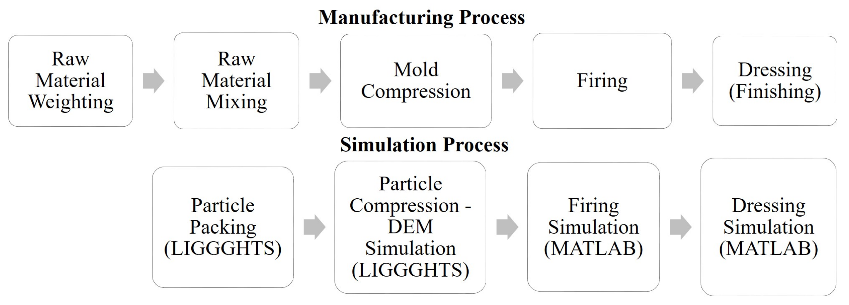
The simulation process follows the generalised fabrication process [16,25] in most of the steps, as shown in Figure 4. The first step in fabrication is weighing the raw material, i.e., the amount of bond material and abrasive particles. Subsequently, the materials are mixed. During this process, pores are created and their distribution is defined by the natural packing between the two components [26]. In the third step, the mixture is poured into a steel cast of the desired grinding wheel shape and compressed by a hydraulic press. The first three steps of fabrication were simulated with the discrete element (DEM) simulation software LIGGGHTS 3.8. After this, particles are being fired (sintered) and dressed, resulting in the final grinding wheel surface. Those two steps were simulated with Matlab 2018b, using the particle output from the DEM simulation.
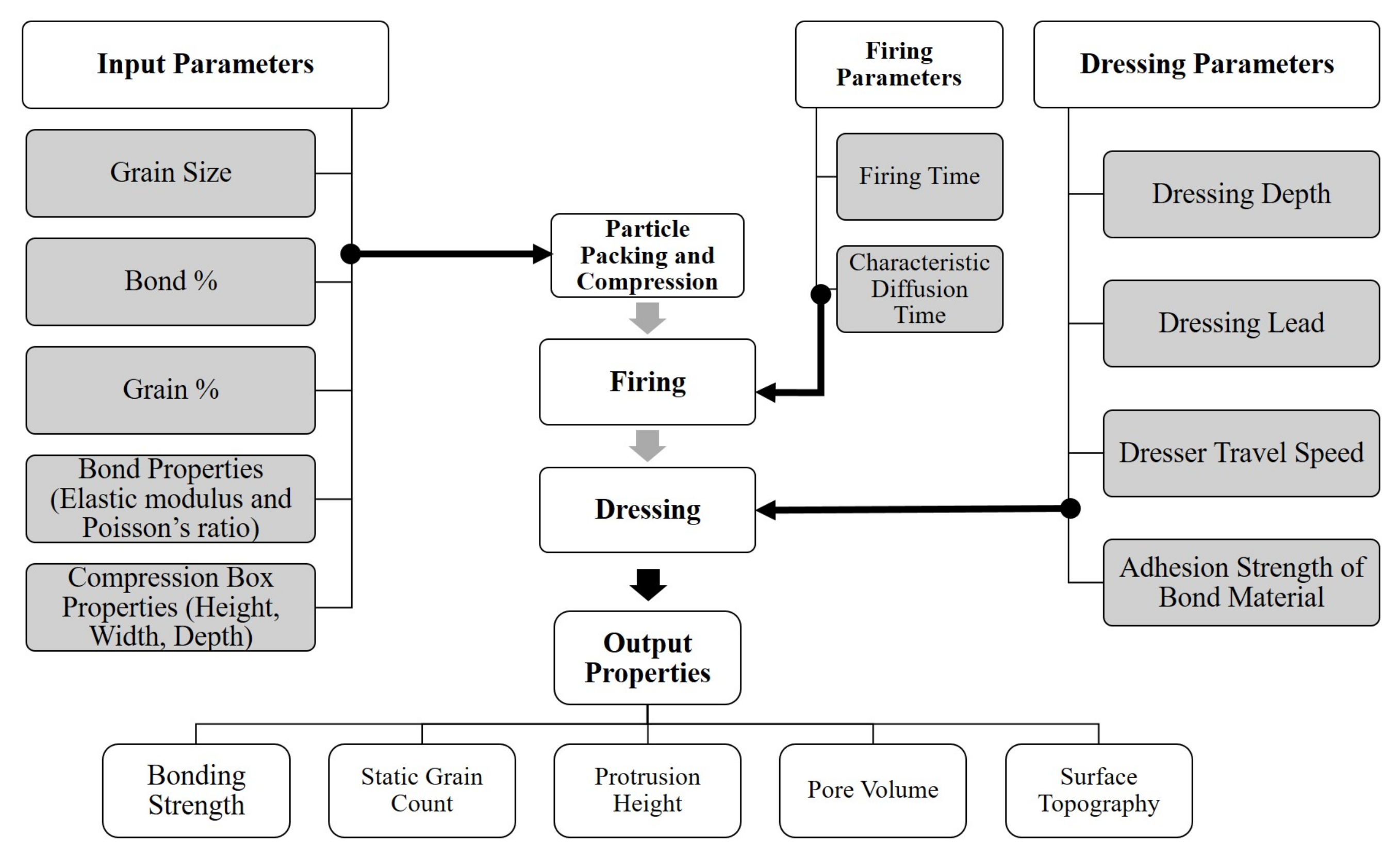
Following the simulation process, all of the parameters of the simulation are defined as displayed in Figure 5. The input parameters, such as material properties and distribution properties, were used in the DEM simulation. For the firing and dressing processes, the corresponding properties were computed in Matlab. The simulation properties acquired contain all quantities of interest, such as bonding strength, static grain count, protrusion height, pore volume, and a particle export for the surface topography.

3.1. Particle Mixing and Packing

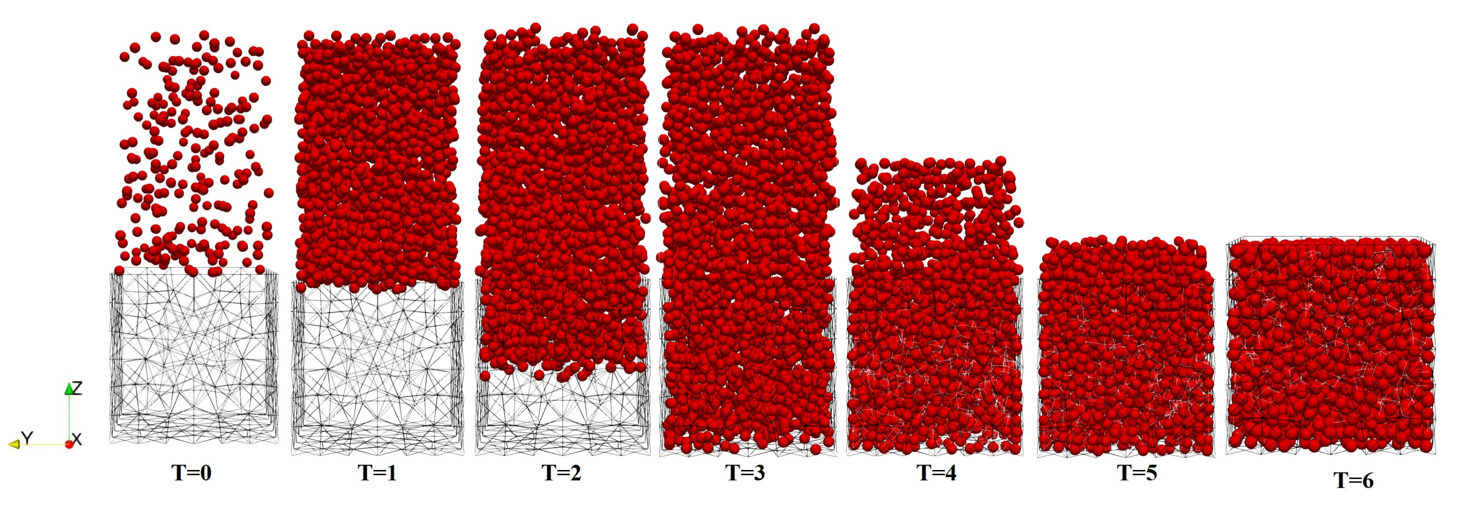
In the simulation, the material mixing is done by creating particles where the bonding material is already surrounding the grain, in comparison to the real fabrication, where this step happens while mixing the grit and the bonding material. The creation of particles in the DEM simulation is done by a stepwise creation of new particles in the time range from T=0 until T=3; see Figure 6. The particles are randomly distributed in a certain area above the metal cast, representing the natural distribution of the mixture. The particles start falling immediately after their creation and the whole system settles down after the creation of particles is stopped at timestep T = 5. Additional particles outside the desired shape are removed, resulting in randomly distributed particles at timestep T = 6.
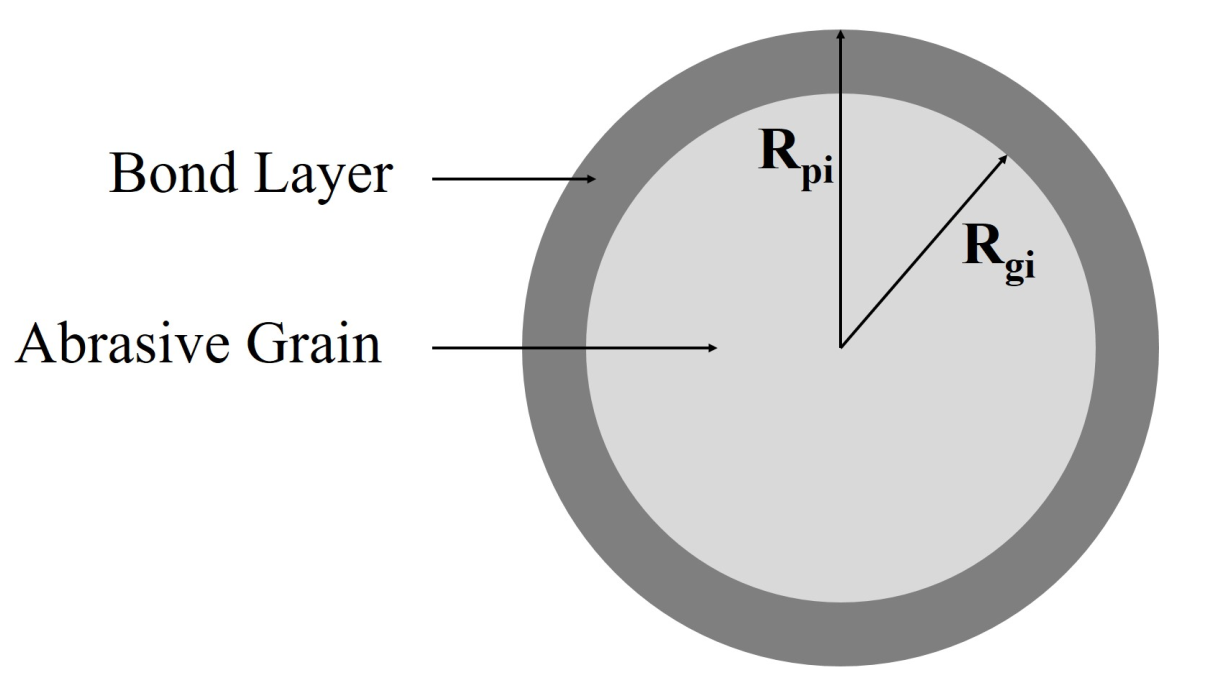
The particles created are a composite of the abrasive grain with radius R g i and the corresponding amount of bond material, resulting in the total particle diameter R p i , as displayed in Figure 7. The total particle diameter R p i is dependent on the distribution of bond material and abrasive grain f b f g , as well as the grain diameter R g i ([16], p. 59)
R p i = R g i · ( 1 + f b / f g ) ( 1 / 3 ) .
The particles considered for the simulation are concentric spheres as it is easier and less computationally intensive to perform the further firing and dressing algorithms. The aim of the study is to develop a simple and a computationally less intensive grinding wheel model to show the principle dependencies and tendencies.

3.2. Particle Compression

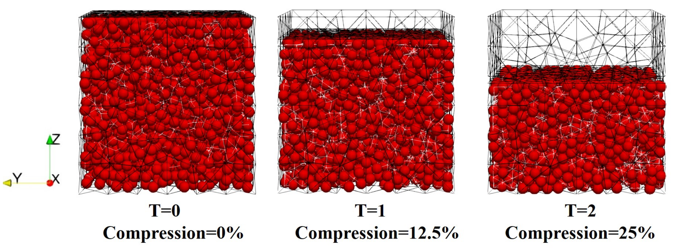
The hydraulic pressure applied is usually between 100 and 5000 PSI (pound per square inch, which is ≈ 0.69–34.5 N / mm 2 ), which is applied for about 10–30 s [16,27]. In the simulation, the particle compression is realised by moving a plane vertically onto the particles and thereby changing the volume. The simulation in this study was performed by varying the percentage of final volume. In the DEM simulation, a horizontal plane is moved for a certain distance per unit time towards the bottom, which represents the real fabrication process [28]. A visual example of the compression process is displayed in Figure 8. The maximum feasible compression is defined when more than 0.5% of the particle radius is less than their initial grain radius R g i . Thus, the simulation represents the difference in material properties of the outer bond material and inner abrasive grain, as the abrasive grain is less compressible than the bond material. Abrasive grains, e.g., silicon carbide, have a Young’s modulus of 400 GPA [27], whereas a vitreous bond material, e.g., clay, only has a Young’s modulus of 6.2 GPA [29].

3.3. Firing

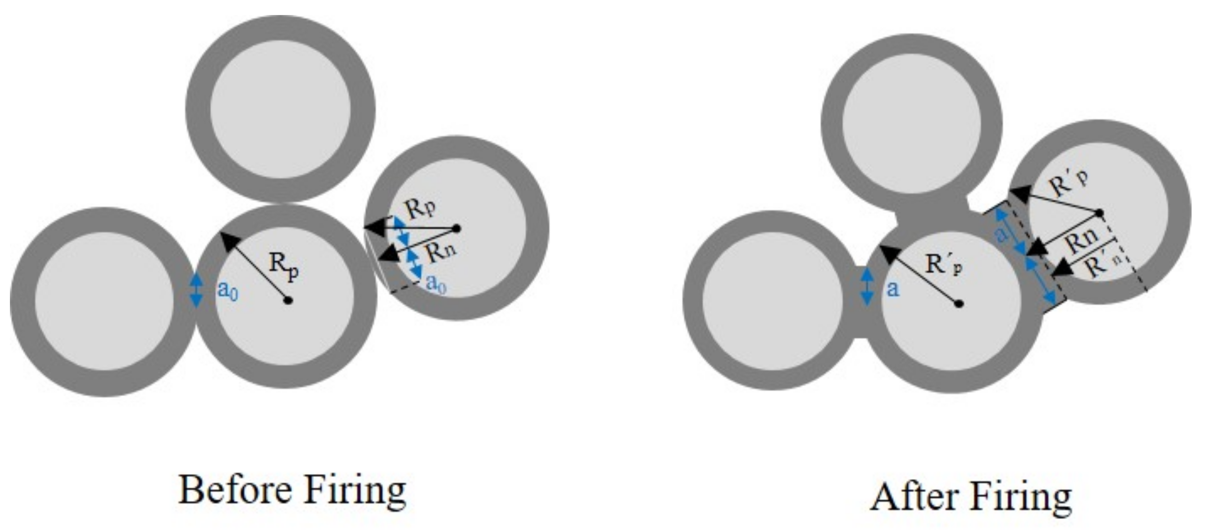
The firing (sintering) of the packed particles was simulated in Matlab by using the exported particle data from LIGGGHTS, containing the position and radius of every particle in contact and the surface contact area of the connection. The first step in the firing algorithm is the calculation of the new neck radius a, as displayed in Figure 9. The characteristic time for the grain-boundary diffusion τ g is used as a material property [30] and the sintering (firing) time for the grain-boundary diffusion [30] needs to be set. With the use of the initial neck radius a 0 [30], the formula for the new neck radius [16,30,31] is derived as
a = a 0 · 192 t τ g ( 1 / 6 )
In Figure 9, the formation of multiple particles before and after firing is displayed. Each particle i in the set of n particles has a radius R p i before firing and a radius R p i after firing. Every connection of a particle (bond) j in the set of m connections has a neck radius a 0 j before firing and a neck radius a j after firing. The calculation of the particle radius R n i (see Figure 9), which connects the particle centre with the respective middle point of the neck, is calculated using Pythagoras’ theorem:
R n i = ( R p i 2 a 0 j 2 )
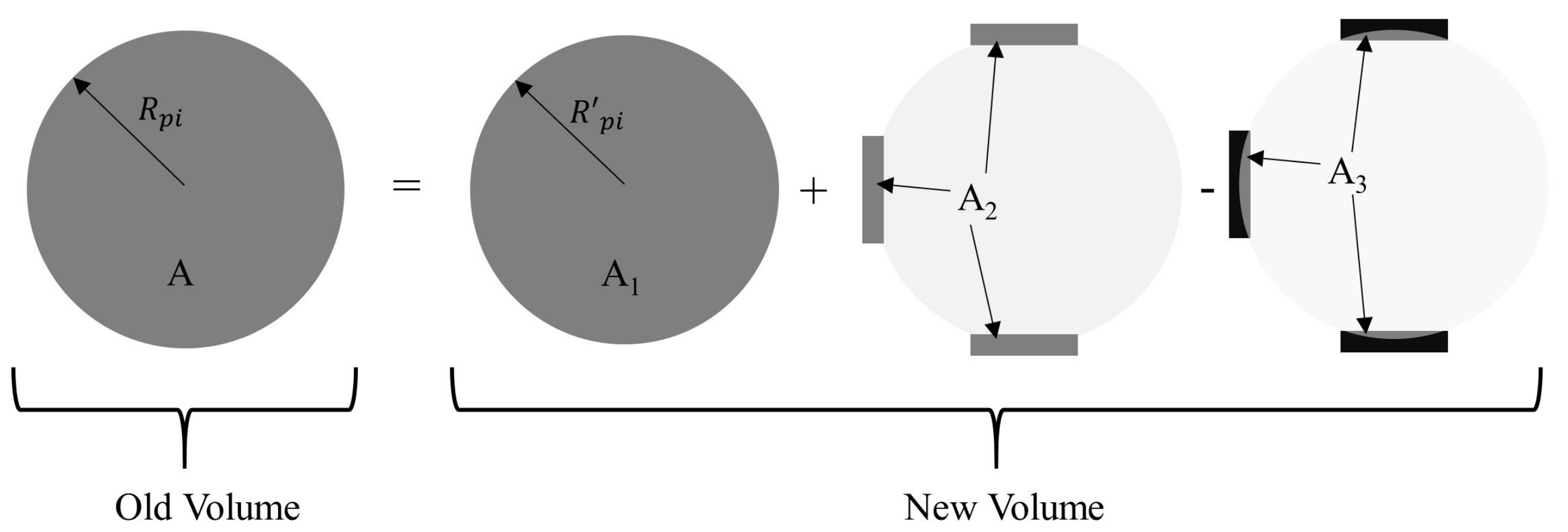
The distance of the particle centre towards the cutting edge of R n i and the new neck boundary is defined as R n i (see Figure 9) and calculated as h i = R n i R n i . The calculation of the new particle radius, as shown in Figure 10, is based on the law of conservation of mass. The equation and its graphical representation are as follows:
( 4 3 π · R p i ) 3 A = ( 4 3 π · R p i ) 3 A 1 + i = 1 n j = 1 m [ a i 2 π · ( R n i R n i ) A 2 π 3 h j 2 · ( 3 R p i h j ) ] A 3

3.4. Dressing

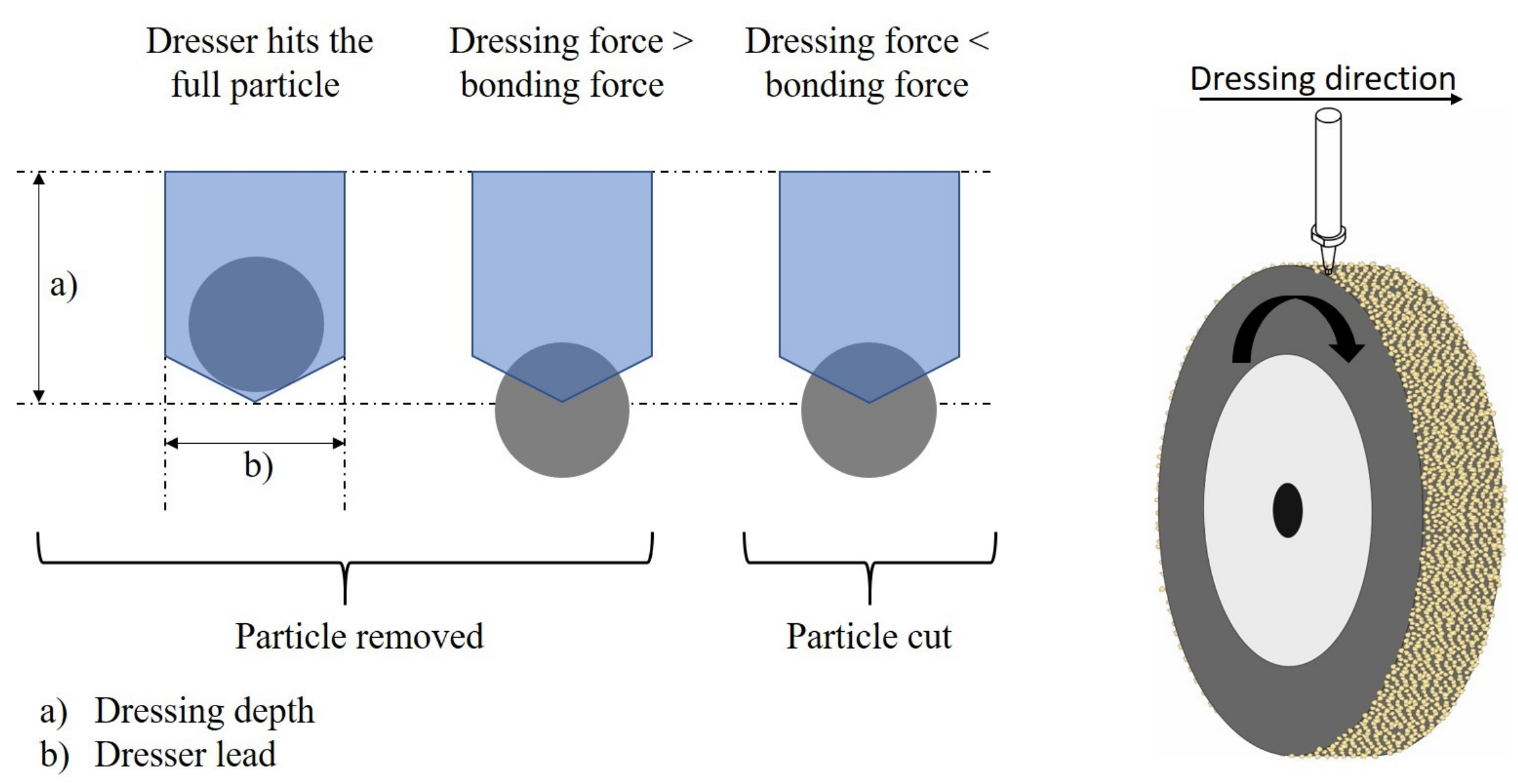
Dressing of particles is usually performed with a single-grit diamond [32] to reduce thickness, to correct balance or parallelism, and to create special contours (e.g., sharp edges) [16]. In the dressing process, the grinding wheel is rotating at a certain speed while the dresser remains in the same position. The dresser moves horizontally at a certain travel speed and cuts along the complete surface area of the grinding wheel. Ideally, the dresser is set to a certain travel speed such that every area on the surface is hit exactly once, without overlapping [33]. For ease of simulation in this study, the cutting angle of the dresser was set to 90°. The effect of different dressing angles and methods on the surface topography is a research area of its own (e.g., [6,33,34]), but generally rests on the principles applied in this study. When the dresser hits a particle, there are three possible situations, as displayed in Figure 11. The first possibility is that the dresser hits the particle at its full surface, resulting in a removal of the grain, independent of the dressing force or bonding force. The second option is that the dresser partly hits the particle, but the dresser force is higher than the bonding force of the particle, resulting in removal of the grain. The third option is that the dresser partly hits the particle, but the bonding force is higher than the force of the dresser, resulting in a grain that is cut (broken).
Complex grain crack propagation at the abrasive grit can be simulated with the finite element method [35,36]. Although grain crack propagation can provide some realistic insights in the dressing process, it is highly computationally intensive. In this research a simple dressing algorithm based on [16] was chosen considering the high number of grits to be dressed, which would be less computationally intensive.
For the calculation of the dressing force F t , an empirical formula is used [32]
F t = 9.631 a d p 0.1992 · f d 0.1774
It is based on the dressing depth a d p (in mm) and the dresser travel speed f d (in mm min ) The bonding force F b is dependent on material-specific properties of the bonding material [21]. In this study, a specific bonding force for the material of F b s p = 800 N / mm 2 was used, depending on the surface area of each bonding a j of a particle. Thus, the bonding force of a particle i is
F b i = F b s p · j = 1 m a j

3.5. Calculation of Output Variables

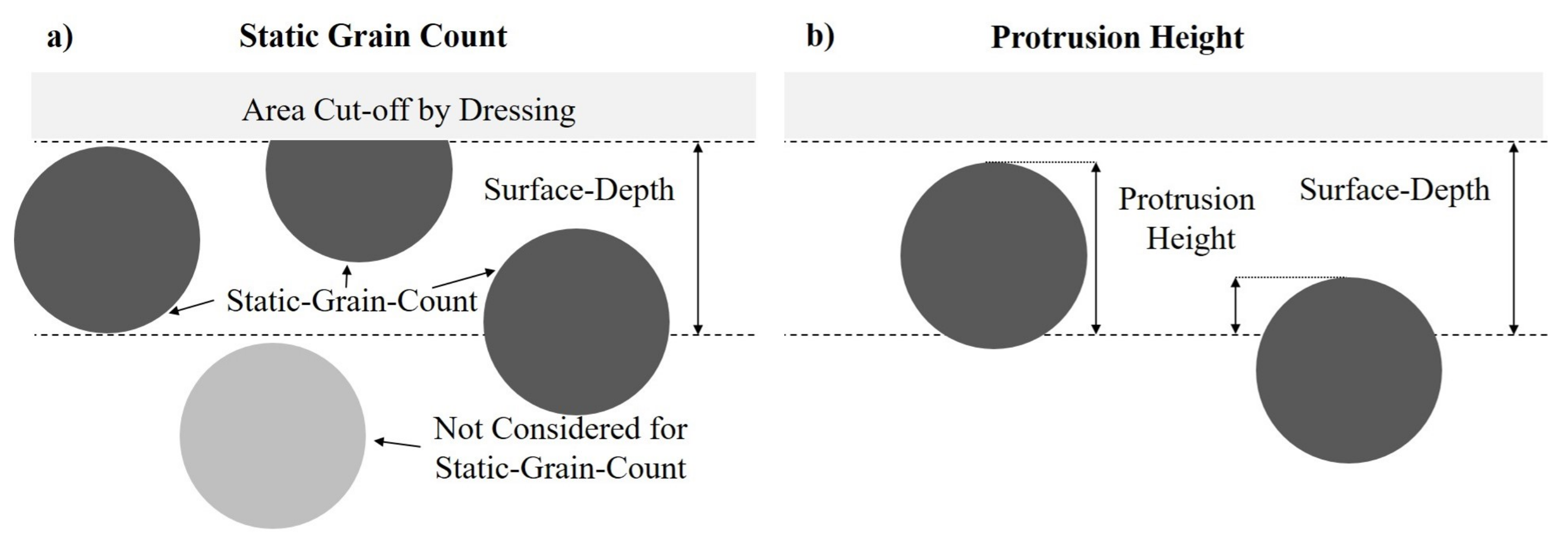
Four major output variables allow the evaluation of the results of the simulation: the bonding strength of the particles, the static grain count, the protrusion height, and the pore volume. The average bonding strength is the mean of the bonding of all particles in the grinding wheel and their respective bondings. The static grain count is the number of grains on the wheel surface in a certain area (see Figure 12a) [16,19], although it differs from the kinematic grain count, which considers only the grains interacting with the workpiece material. The static grain count value is not always reliable as it depends on an arbitrary surface depth [19], although it is commonly used in research [5,9,17,19,23]. To solve this issue, this study introduces an alternative static grain count, where the surface depth depends on the average diameter of particles. Thus, the different grain sizes can be compared more reliably, as the surface depth adapts towards their properties and to the changing height of the bond surface.
The protrusion height was calculated as described in [19] and is visualized in Figure 12b. The protrusion height is defined as the height difference of a grain tip from the bond surface [19]. The bond surface was set to an arbitrary height making it difficult to compare the obtained results with other studies [19]. In this study, all the particles that were a part of the static grain count along a specific depth were considered for the measurement of the surface depth. For the alternative protrusion height, the alternative surface depth definition was applied and deviates from the standard measurement (protrusion height). During grinding, the pores in front of grains provide channels to store lubrication and clearance for chips to escape from the wheel matrix [24]. In some high-performance grinding applications, a large pore volume is needed. The effective pore volume, in conjunction with the protrusion height, enables the prediction and control of the amount of chips stored or carried by the grinding wheel. Figure 13 describes the calculation of the effective pore volume in front of a grain.

3.6. Surface Calculation and Modelling

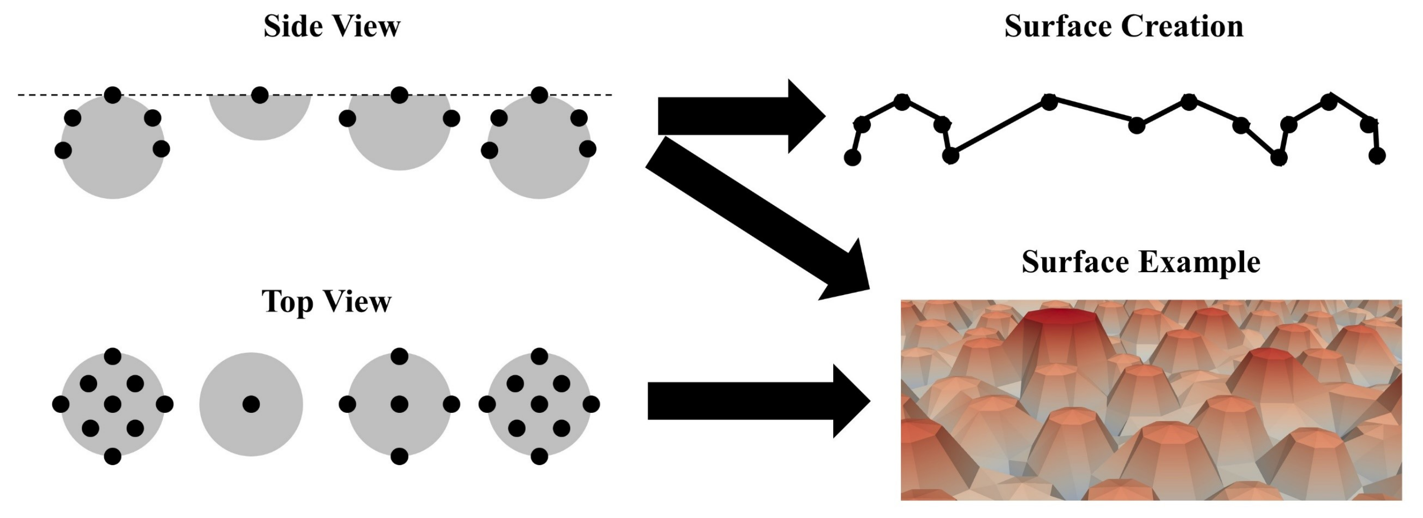
For visualising the grinding wheel topography, the software ParaView 5.7 was used. To properly display the surface, output coordinates were defined in a MatLab simulation. Figure 14 displays how the coordinates for different particles are created and how the surface is visualised using these points. In the first step, particles visible on the surface (top view) are identified. In the second step, the tip height of the particle is identified. In a third step, up to 16 additional data points are created to properly and realistically visualise the shape of the abrasive particles. Afterwards, these additionally created data points are checked for their spacing and eventually removed for smoothing the surface output and the removal of unintended spikes. In the last step of the visualisation, the exported data points are connected resulting in a virtual wheel topography.
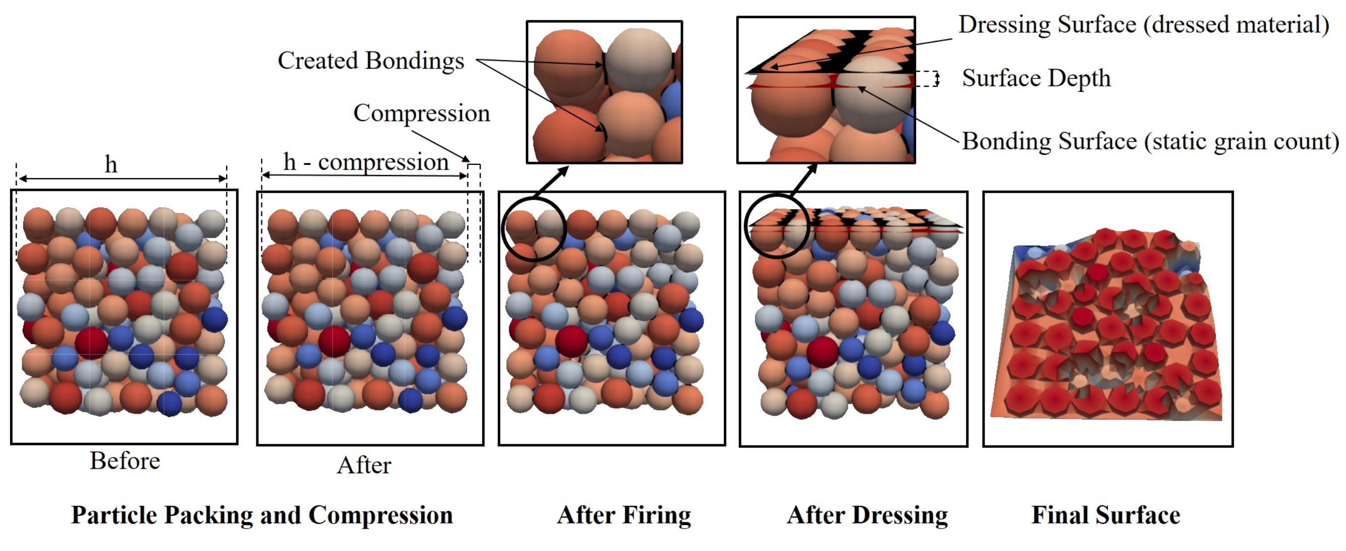
All steps conducted during the simulation were visualised to enhance the understanding as well as checking for reliability of the calculations and assumptions. Figure 15 shows an example visualisation of all steps using the grit size 30 with a 5% compression of the particles.

4. Results and Discussion

In this study, the simulation properties for the particles, the firing, and the dressing were selected similar to [16] to obtain comparable results and can be found in Table 1. The size of the modelled metal cast was adjusted based on the chosen grit size, such that the number of particles at the perimeters of the cube remained constant at about 25 particles. The simulation is extendable and is not dependent on shape or size of the cast. Box geometry was initially chosen as it is less computationally intensive. For the calculation of the output variables, the surface depth was set to 0.1 mm. For the particle compression, the material properties of the vitreous bond material [21], which has been empirically studied in [29], were used. The wheel speed for dressing was adjusted such that the dresser lead hit every area of the grinding wheel just once. For the alternative measures, i.e., alternative static grain count, alternative protrusion height, and alternative effective pore volume, the surface depth was set to the average radius of the compressed and sintered particles of the respective grit size. Nine different grain sizes were used (grid numbers 20, 24, 30, 36, 46, 54, 60, 70, and 80), as defined in Table 2, with a size distribution and average grit size, according to [37]. An example of the size distribution used for grit size 46 is shown in Figure 16. The standard deviation for the normal distribution was calculated for a 95% confidence interval, thus the grain diameter values were in between the maximum and minimum diameter with a 95% confidence interval. The particle radius (grain + bonding) was calculated according to Equation (1), with a grain fraction of 49% and a bond fraction of 10%, and the rest consisted of pores.
The following results from the simulation performed have been categorised into four subsections. The first section describes the effect of the output variables for a percentual dressing of 10%. The second section validates the virtual grinding wheel model with topographical measurements based on experiments performed at our laboratory and measurements obtained from the literature [16]. The third section talks about the effects of variation of percentual dressing depth on the output variables. The fourth section describes visual aspects of the grinding wheel topography based on the various output variables. The final section discusses the practical aspects of the selection of a grinding wheel for a particular application, using the grinding wheel model.

4.1. Analysis of Output Parameters Based on Dressing 10%

In this section the output variables compression, bonding strength, alternative static grain count, alternative grain protrusion height, and average effective pore volume are analysed for the virtual wheel simulation with a percentual dressing of 10% for grit sizes 20–80.

4.1.1. Compression

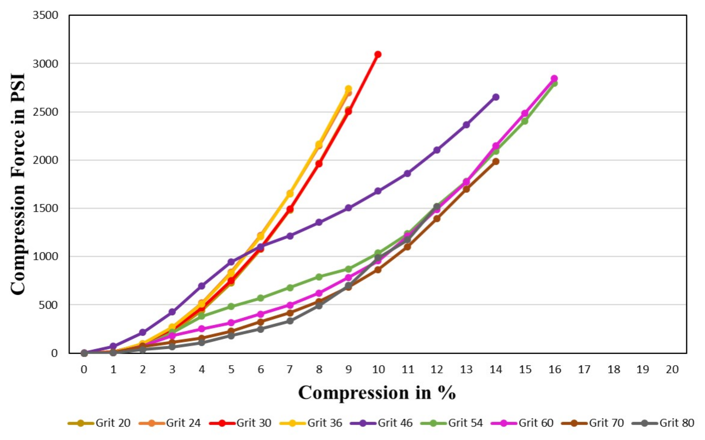
The compression force (in PSI) used for a certain percentage of compression of the particles is displayed in Figure 17. It can be observed that the maximum feasible compression forces increase with the increase in percentage of compression. The maximum values reached lie between the range of 2500 and 3000 PSI. Moreover, a decreasing particle size leads to a higher percentage of feasible compression. For all grit sizes, the slope seems to be linear to slightly exponential. Eventually, there is a tendency of a more steep slope for decreasing grit sizes (increasing particle size); the reason could be that the larger particles have a larger contact surface with respect to the horizontal plane, hence requiring a higher compression force at a higher percentage of compression. In general, the larger the grit size (the smaller the particle size), the higher the percentage of compression for the same compression force. Therefore, the smaller the particle size the more tightly it could be packed.

4.1.2. Bonding Strength

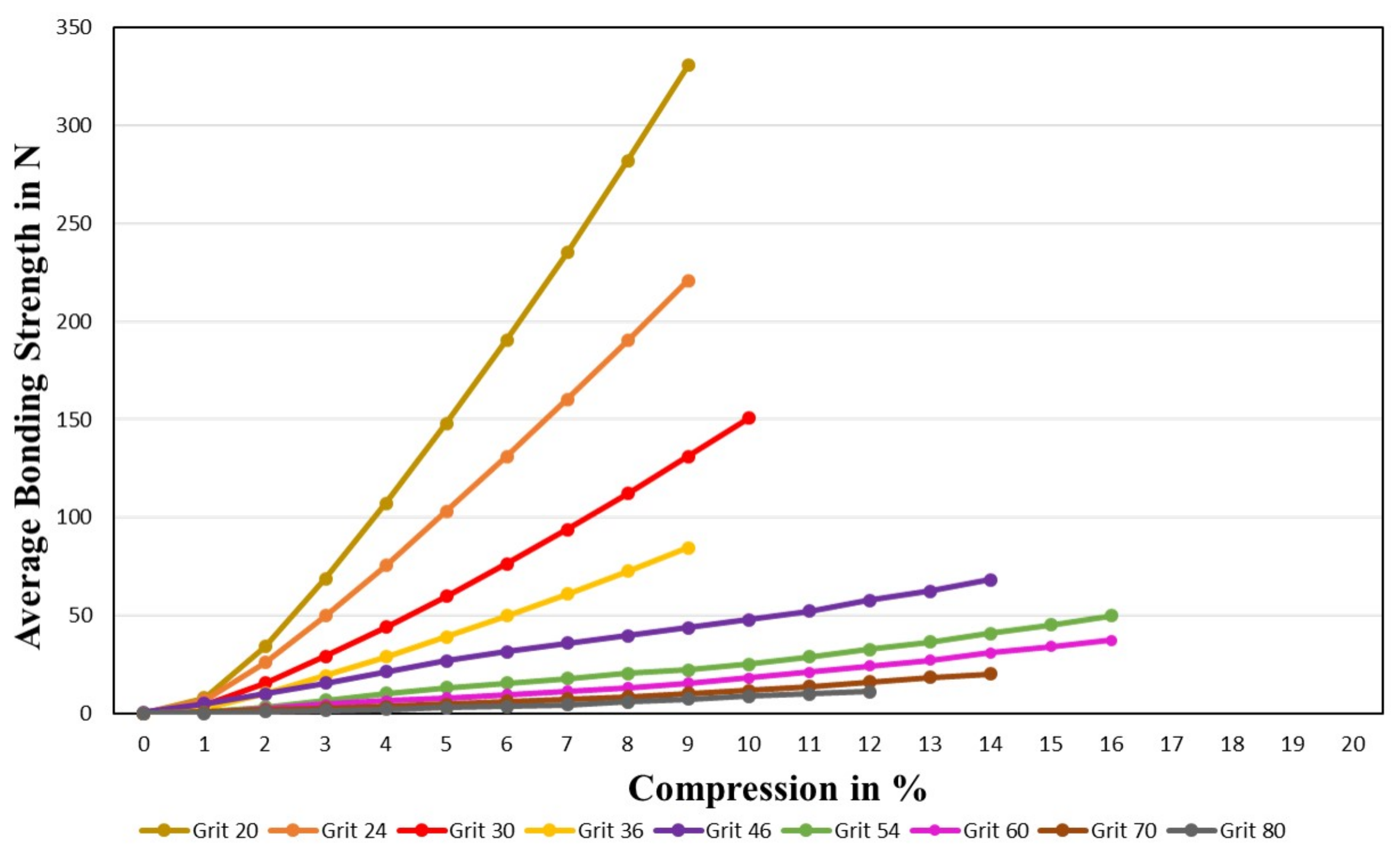
The average bonding strength is compared to the percentage of compression in Figure 18. The average bonding strength of all grit sizes is almost linear to the percentage of compression, i.e., the higher the compression of particles, the higher the bonding strength, which results from an increased contact area. At a higher percentage of compression the particles are more tightly packed and fused together, explaining the increase in bonding strength.
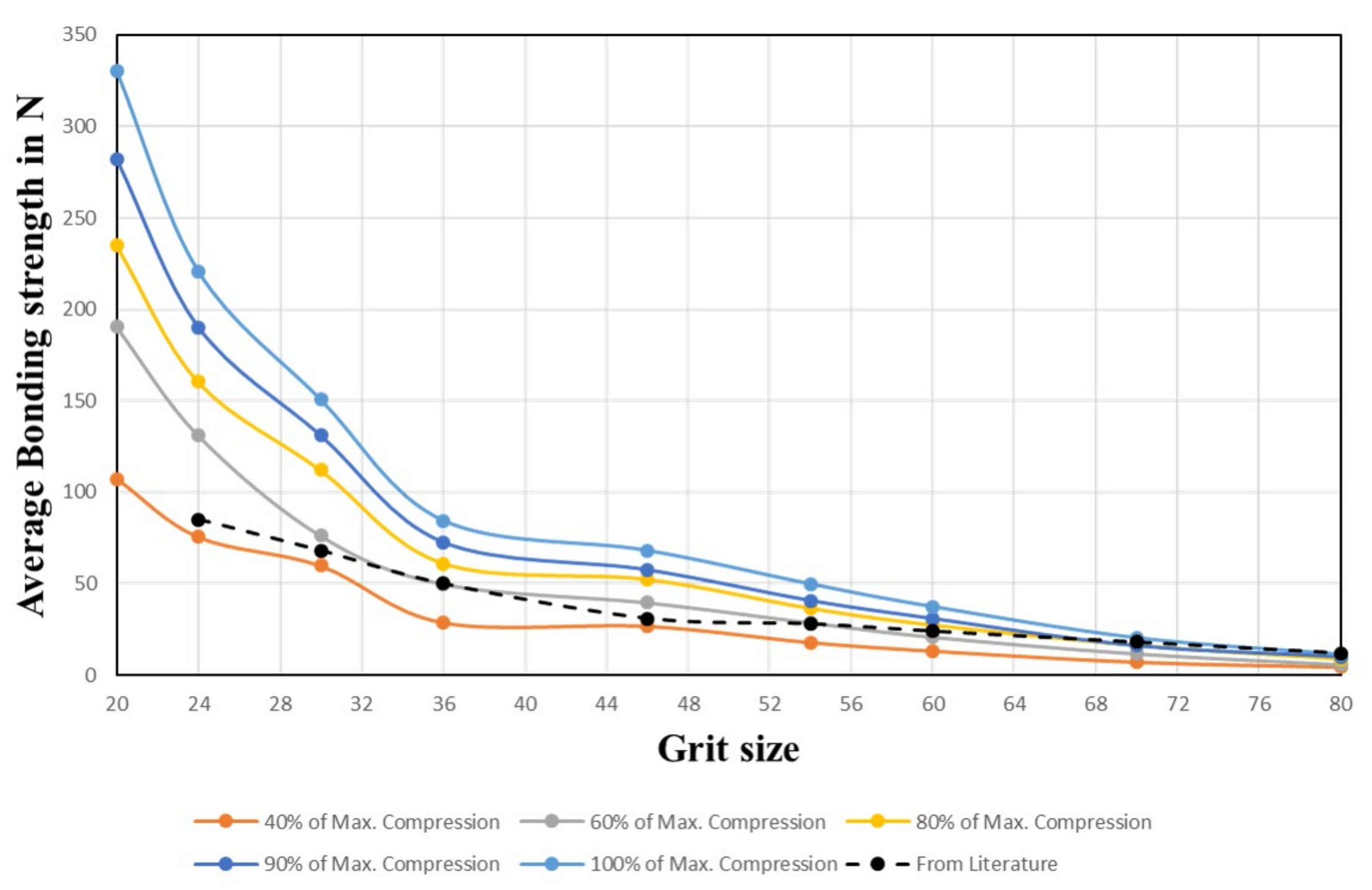
In Figure 19 the average bonding strength is compared to different percentages of the maximum feasible compression (set to 100%) for all grit sizes. The plot shows that a smaller grit size (increasing particle size) leads to a higher average bonding strength. At 100% feasible compression, grit 20 has the highest maximum average bonding strength of 330 N, and grit 80 has the lowest of 11 N. The reason is that with increasing particle size, the bond surface fused together is larger and thereby the bonding strength is higher. Hence, larger grit sized wheels could be used for coarse grinding applications and smaller grit sized wheels for fine grinding applications. The characteristic slope of the bonding strength is very similar for different percentages of compression and is comparable to the empirical results from [38] (p. 116). The characteristic slope and maximum values from the literature fit well with the simulation of 40–60% of maximum compression in this study.

4.1.3. Alternative Static Grain Count

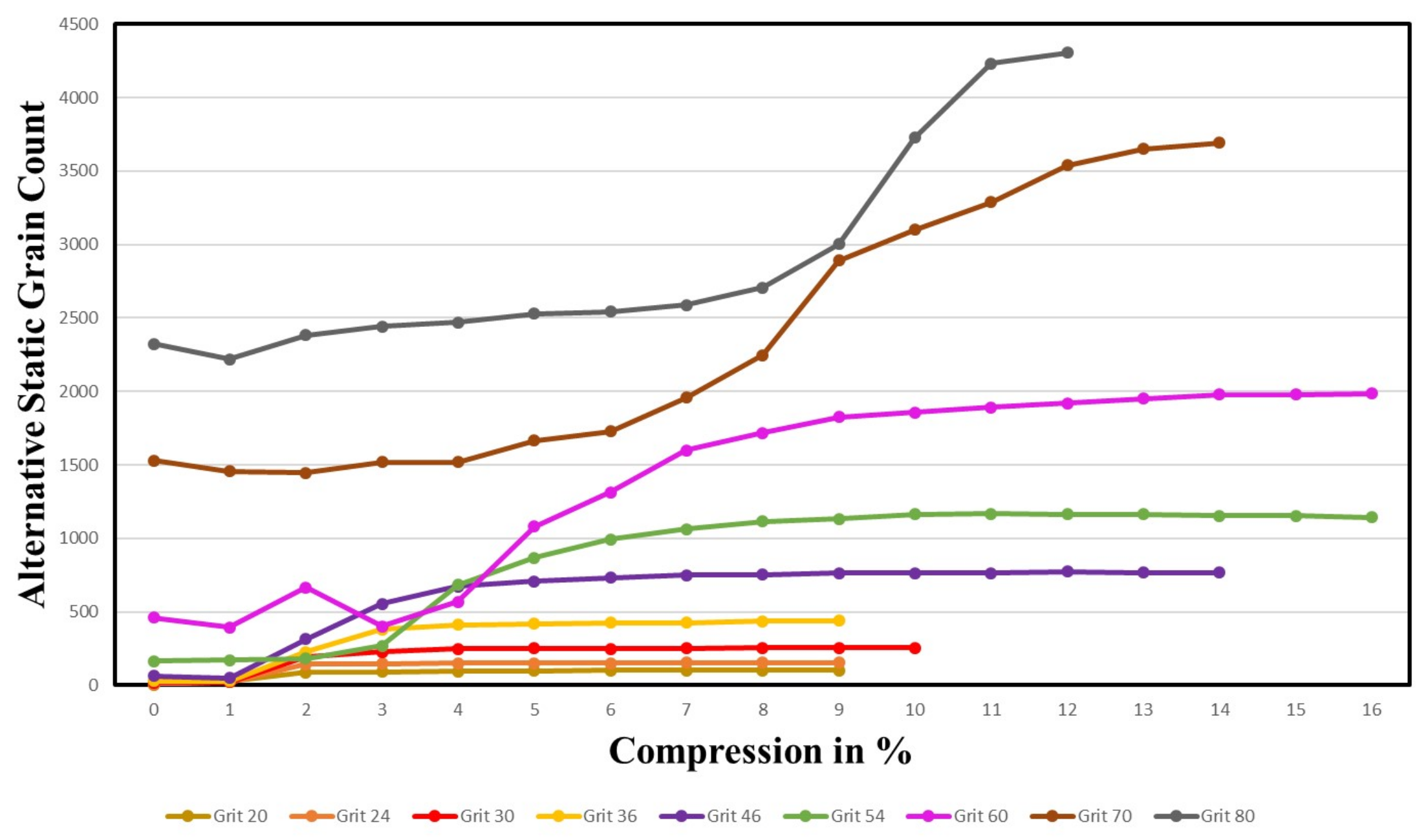
The alternative static grain count per cm 2 in comparison to the absolute percentage of compression is displayed in Figure 20. For the maximum possible compression, the alternative static grain count is the highest for grit 80, decreasing with grit size, with grit 24 having the lowest static grain count, which is in line with the theory and empirical results of [19] and simulation of [16]. Remarkably, all the plots for different grits show a similar characteristic slope: in the very beginning there is a slight but constant increase, followed by an exponential increase. Eventually, the slope becomes constant for increasing compression levels. Thus, a value close to the maximum static grain count is reached before the maximum compression. This tendency is observed to be more pronounced with the larger grit sizes.
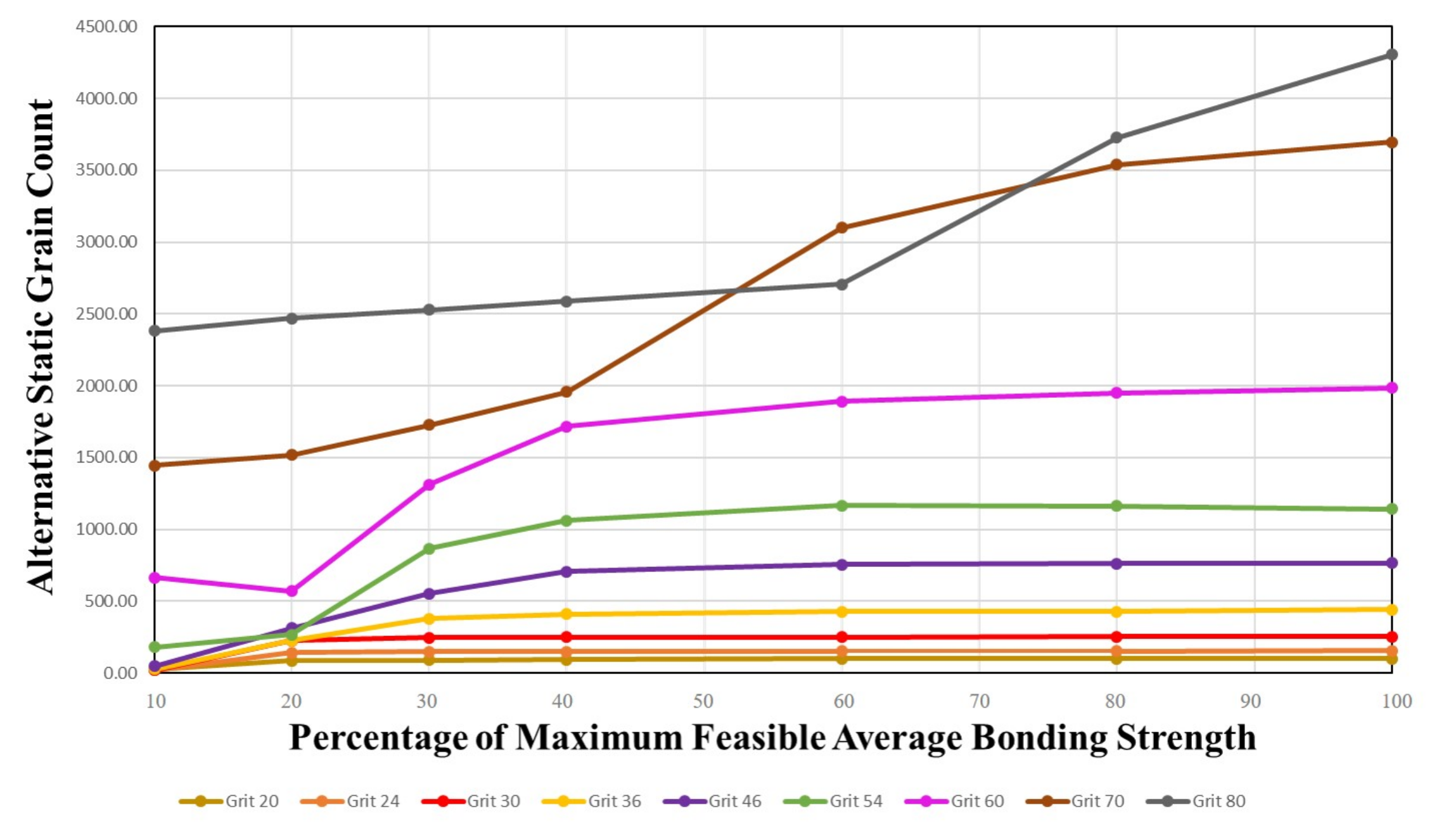
In Figure 21 the alternative static grain count is compared to the percentage of maximum feasible average bonding strength. This plot shows a similar picture to the previous Figure 20, but highlights a sharp increase in bonding strength between 20% and 60% of the maximum average bonding strength with almost every grit reaching its peak (or close to it) at 60% of the maximum average bonding strength.

4.1.4. Average Grain Protrusion Height

The protrusion height, which is defined as the height of the grain tip from the bond surface, is an important parameter on which the roughness of the generated work surface and the wear of the wheel are dependent to a large extent. The measure of the alternative protrusion height was set at 35% of the particle diameter, as recommended in [36]. On employing the normal protrusion height measure at a constant height of 0.1 mm as in [16], it becomes difficult to compare the grit sizes with each other. The determined surface depth makes it impossible for some grit sizes (e.g., 20, 24, and 30) as the particles below the top row also get considered for calculation due to compression. This effect is undesirable. Thus, an alternative definition of the surface depth was used to measure the alternative average protrusion height, making it possible to compare the grits with each other and to represent the bond surface realistically.
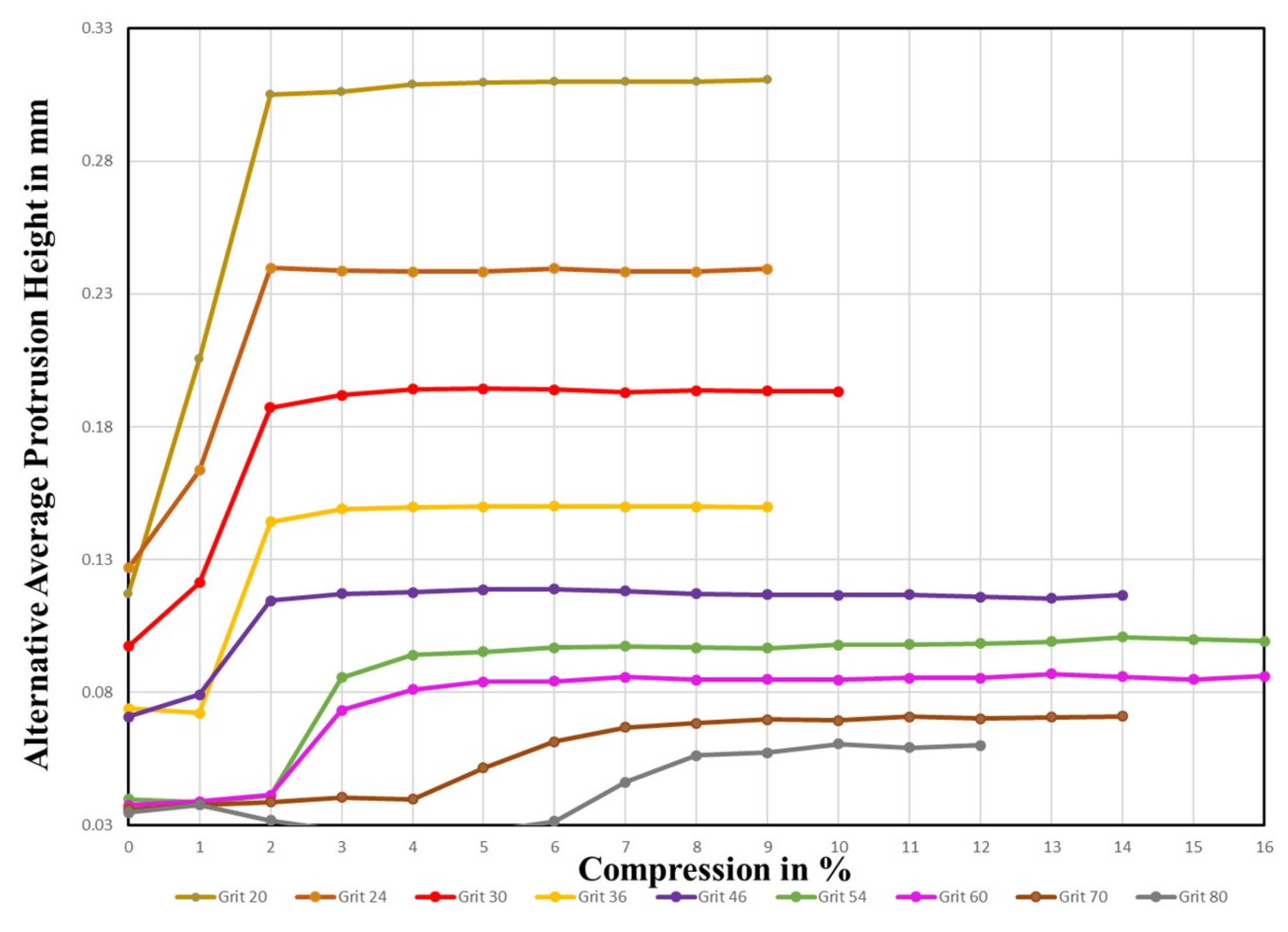
A comparison of the average alternative protrusion height of particles considered in the static grain count and the percentage of absolute compression is displayed in Figure 22. The average protrusion height for all grits starts with a lower value and then sharply rises until 3% compression and remains steady for higher compression levels. There is an exception seen in grits 70 and 80, where the maximum is reached at 7%. A clear trend for a decreasing protrusion height with increasing grit size (decreasing particle size) can be observed, which is in line with the simulation results of [16] and empirical results [19]. On comparing the computed protrusion height values with the simulation results of [16], the values are analogous, although for smaller grits the values in this study are slightly higher. This might be a consequence of differences in the compression levels. Another study [36] suggests that the average protrusion height of a particle is around 35% of the grit diameter, e.g., for grit 54 it is 0.0955 mm. Hence, values in this study are in a very reasonable range.
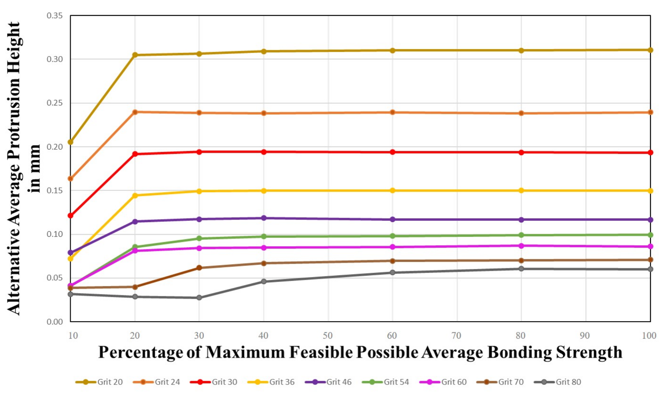
In Figure 23, the percentage of alternative average protrusion height of the particle is compared to the percentage of maximum feasible average bonding strength. There is a significant increase in the measure for smaller grit size (increasing particle size). Consequently, the larger the particle diameter, the higher the protrusion height. For all grits, a maximum is reached at about 30% of the maximum feasible average bonding strength. The total alternative protrusion height is highest for grit 20 and decreases with decreasing particle size. As the real surface depth might be represented more realistically by the alternative surface depth, which is adaptive towards the particle size, it is important to take this result into account when choosing the right grit size.

4.1.5. Average Effective Pore Volume

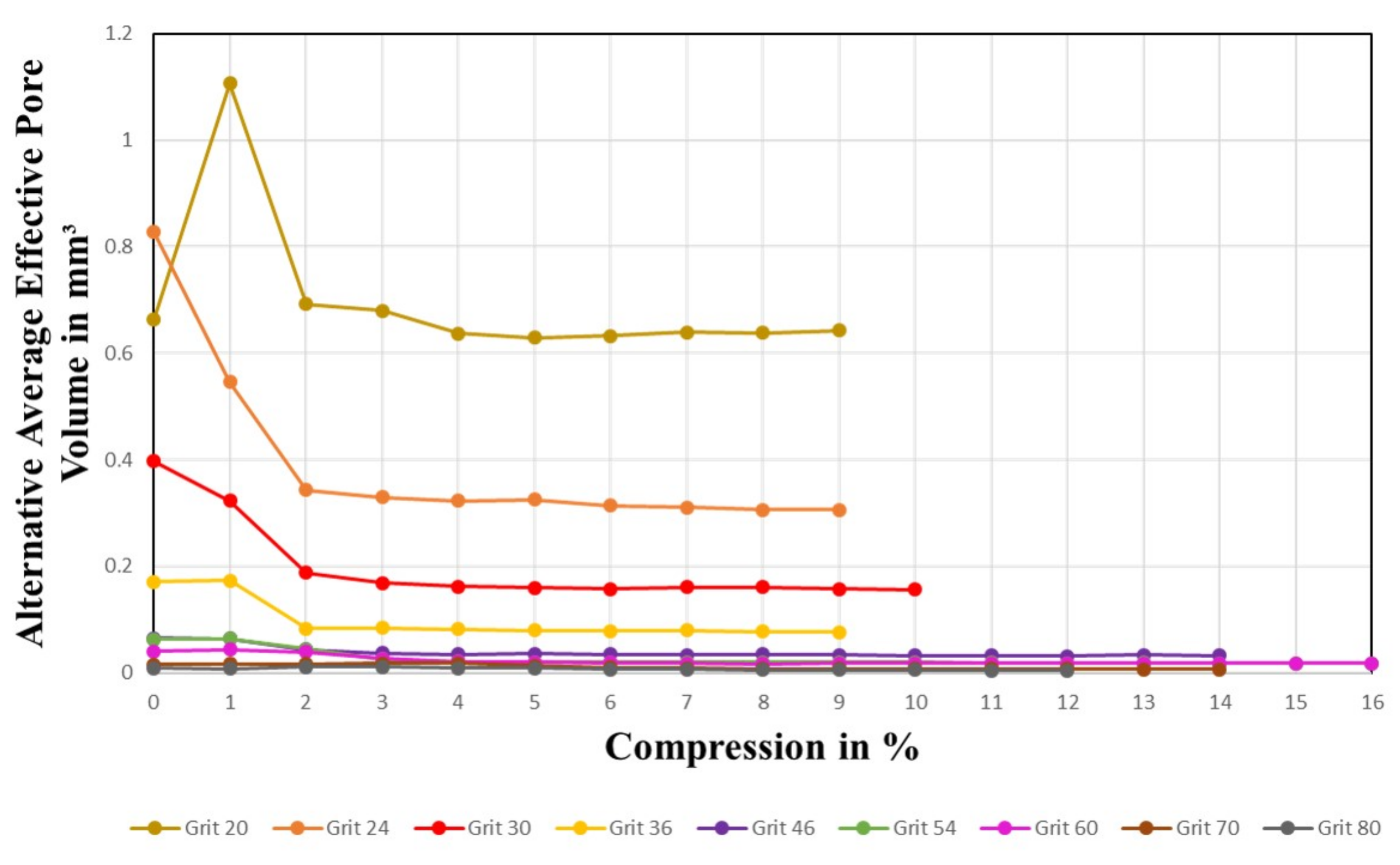
The average effective pore volume for different compression levels and grit sizes is compared in Figure 24. The effective pore volume of a particle in the static grain count is decreasing with increasing grit size (decreasing particle size). The pore volume seems to decrease for all grits with increasing compression levels and eventually reaches a minimum at about 3% compression and then remains steady.
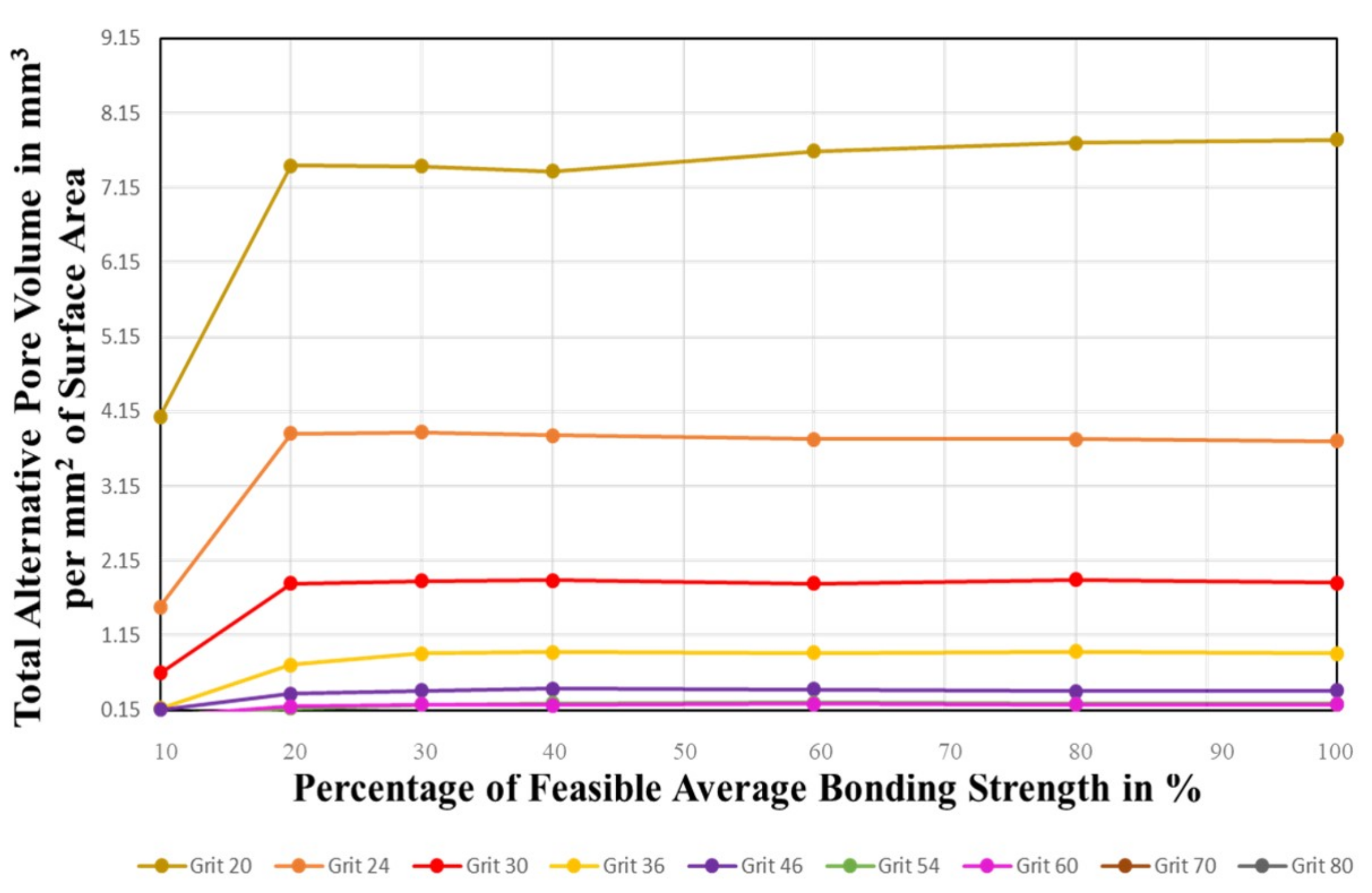
To examine the pore volumes in depth, the total pore volume in mm 3 per mm 2 of the surface area is compared for different grits and compression levels in Figure 25. This plot makes it possible to directly compare the effect of grit sizes on the effective pore volume. The total pore volume is adding up the effective pore volume for all grits in a certain surface area. In comparison to the effective pore volume, the total pore volume increases until reaching a maximum at 20% of the feasible average bonding strength and remains steady afterwards. In this comparison, a decreasing grit size (increasing particle size) shows a clear tendency of a higher total effective pore volume. We infer that with increasing particle size, the higher total effective pore volume offers more space for the lubricant and abrasive material to be stored, thereby increasing the endurance of the grinding wheel.

4.2. Grinding Wheel Measurement and Model Verification

Two silicon carbide grinding wheels were measured with the help of a white light microscope and the measurements made were used to verify the simulation model based on the static grain count and protrusion height.

4.2.1. Grinding Wheel Measurement Platform

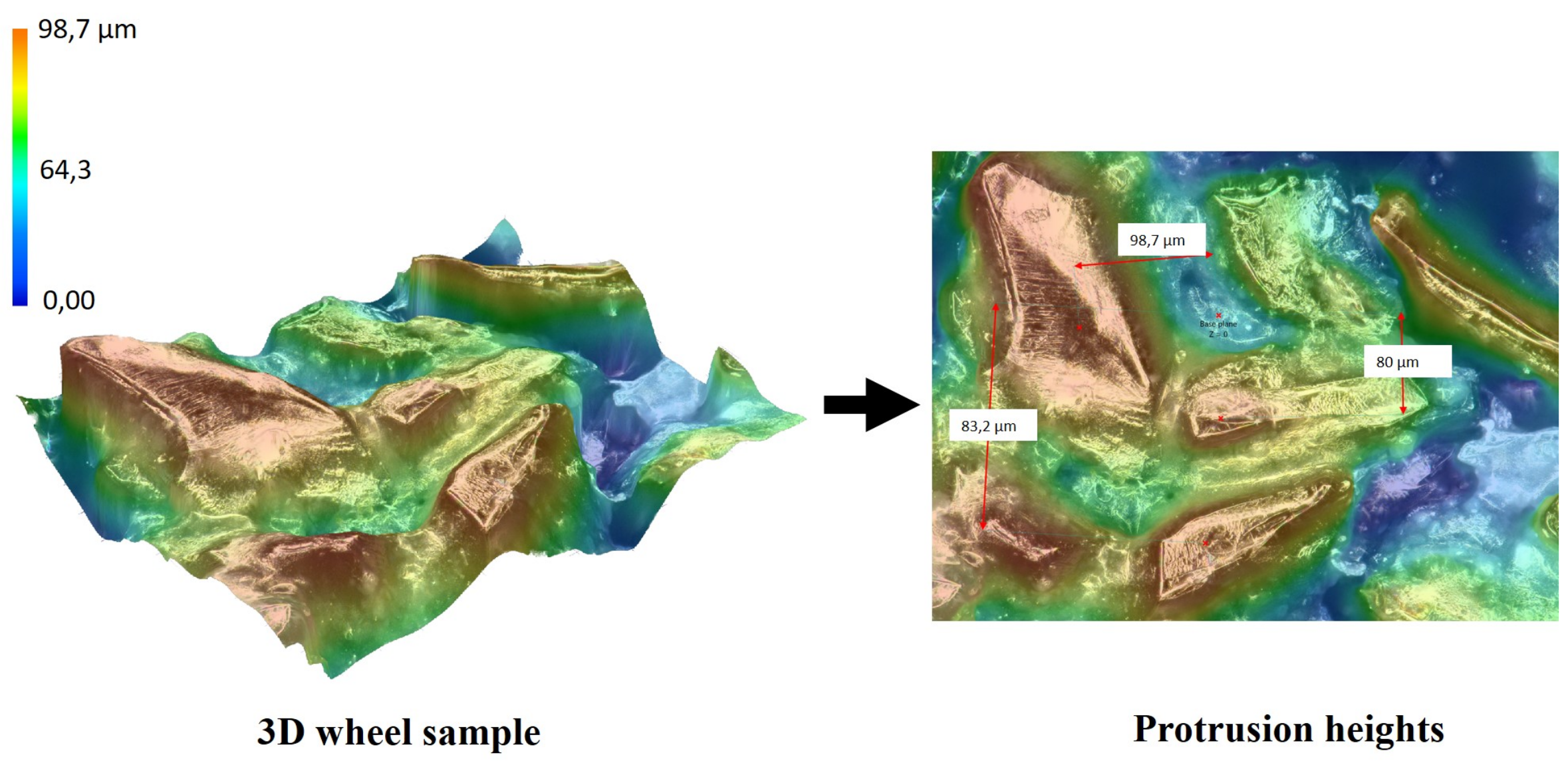
To validate the model in terms of the static grain count and protrusion height, two silicon carbide wheels with grit size 60 and 80 were measured under a Keyence VHX-7000 microscope to examine the 2D and 3D grinding wheel surface topography; see Figure 26. The 2D grinding wheel topography was analysed to obtain the static grain count as shown in Figure 27. The static grain count is the number of grains measured per square centimetre on the wheel surface. In this study, three areas were randomly chosen on the grinding wheel surface for both grit sizes to calculate the static grain count, and the protrusion height was measured as the distance from the grain tip to the bond surface. Therefore, the 3D wheel surface was obtained from the three randomly chosen locations on the wheel surface as shown in Figure 28.

4.2.2. Model Validation

The simulations with a percentual dressing of 10% were initially compared with measured wheel topography results from experiments performed at our laboratory and from the literature [23]. The simulation model was validated based on two output parameters, the static grain count and the protrusion height, which were extracted at maximum compression.
Figure 29 describes the static grain count as a function of the grit size. It can be observed that the simulations can predict the static grain count per cm 2 with good accuracy with the measured grinding wheel topography data (experimentally obtained and in the literature [23]). Over the compared grit sizes the simulated static grain count values do not deviate more than 5%. It is also observed that the static grain count increases with an increase in the grit size (decreasing particle size); this tendency is also observed from the simulation results.
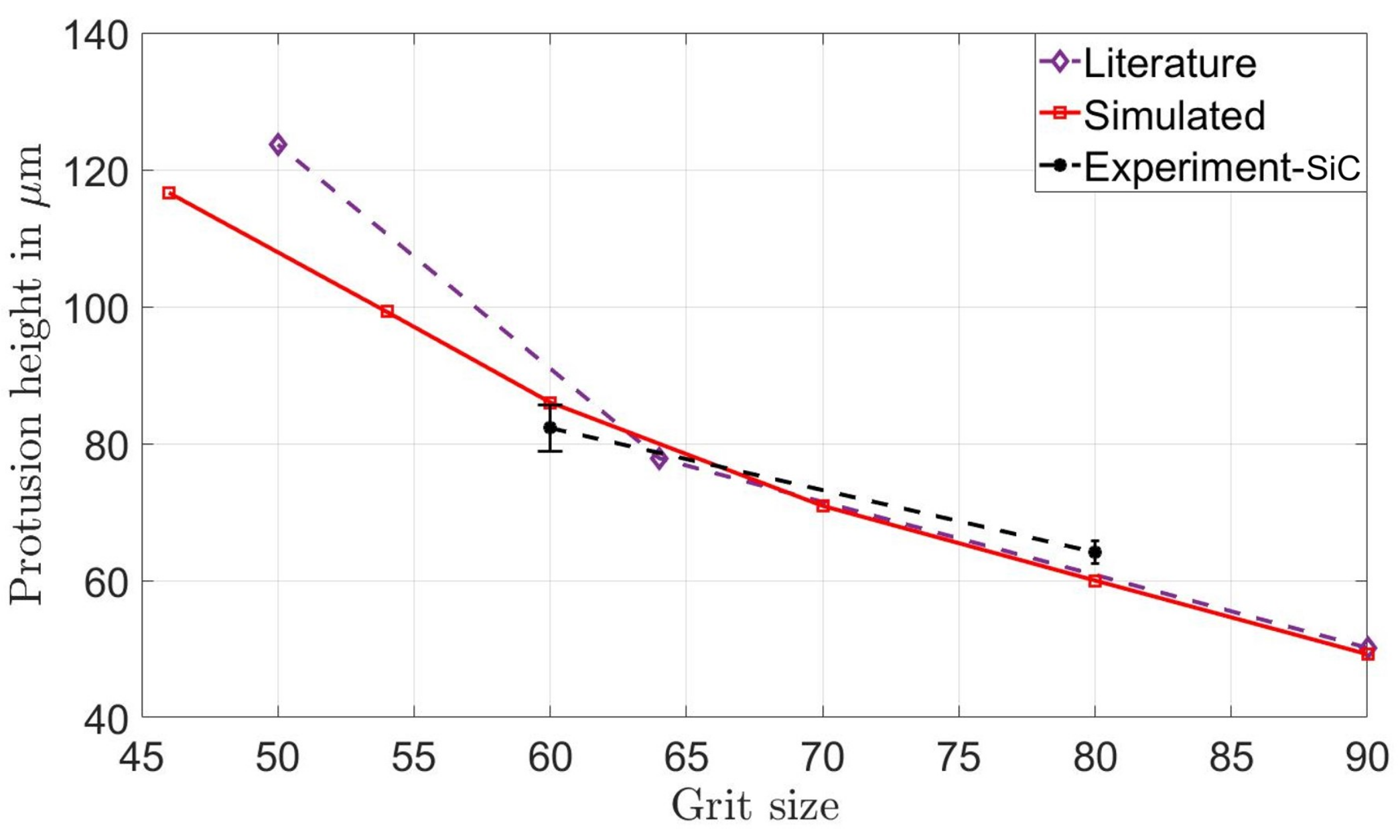
Figure 30 describes the protrusion height as function of the grit size. It can be observed that the simulations can predict the protrusion heights within the accepted variation range as per the measured grinding wheel topography data (experimentally obtained and in the literature [23]). On comparison of the measured protrusion height over various grit sizes, the simulated values do not deviate more than 5%. It is observed that the protrusion height decreases with an increase in grit size (decreasing particle size). Hence, the results of the virtual grinding wheel simulation model are in good agreement with the topographical measurements from experiments performed at the laboratory and measurements made by [23].

4.3. Effects of Fixed vs. Percentual Dressing (Percentage of Average Grit Diameters)

According to the previous studies performed by [16,18], the dressing depth is set to a constant value of 0.1 mm. This might make the generated surface incomparable for different grit sizes. Therefore, this section focuses on a set of simulations that were performed to study the influence of percentual dressing depth. The dressing depth was varied from 5% to 60% of the average particle diameter in order to better understand the effects on the grinding wheel topography of the dressing simulation. The grit sizes of 20, 30, 46, 60, 70, and 80 were considered for this study.
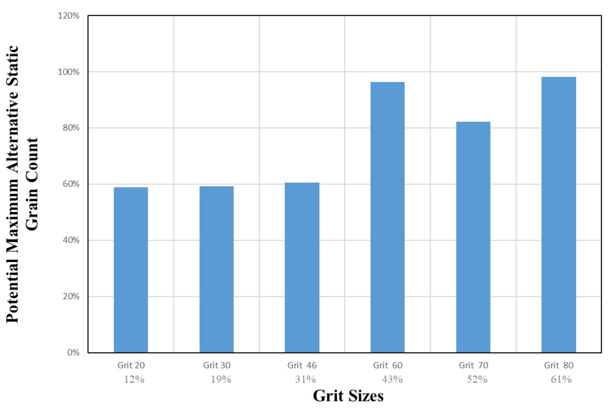
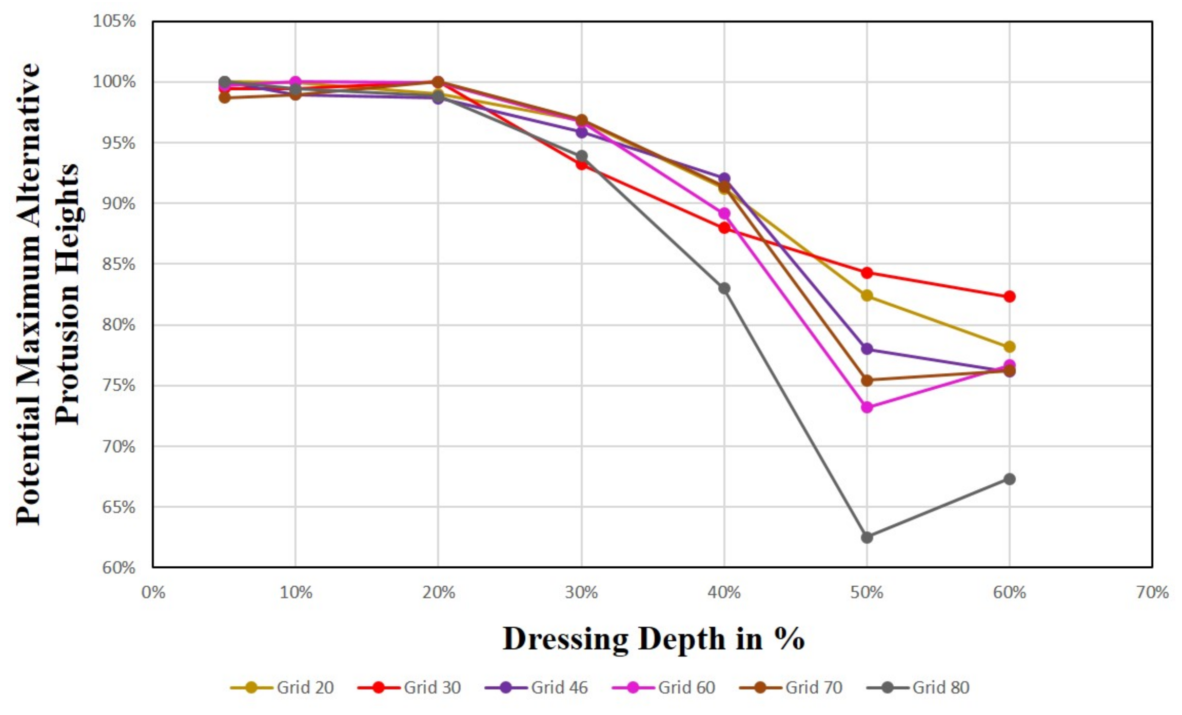
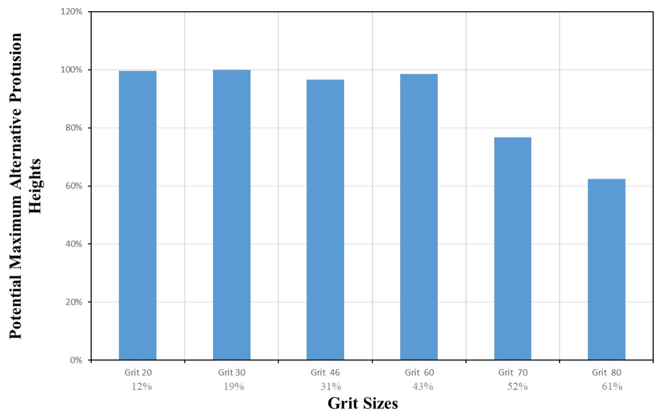
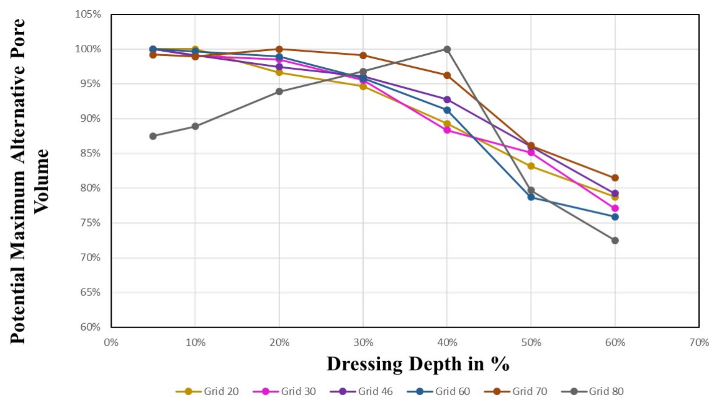
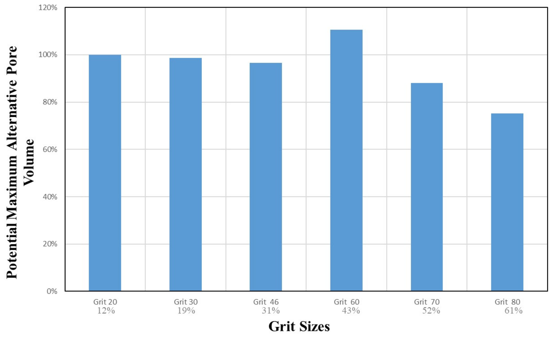
To compare the results from study [16] to the current study, the fixed dressing depth was recalculated in terms of percentual values of the average particle size as shown in Table 3. Varying the dressing depth parameter between 5% to 60% enabled the comparison of various output parameters of the current study with that of the previous study [16]. In Figures 31–36, the maximum potential output values for the various grit sizes are plotted against the percentual dressing depths and in Figures 33, 35 and 37 the maximum potential output values are plotted against the grit sizes.

4.3.1. Bonding Strength on Surface

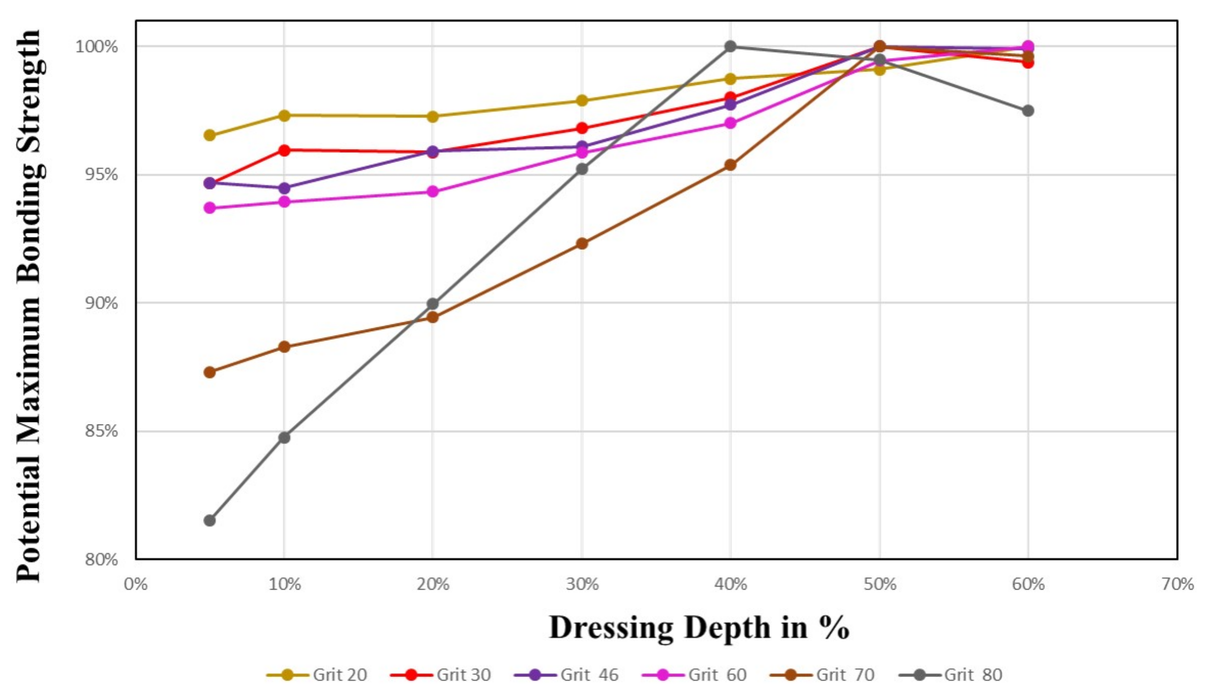
In this section, the variation of bonding strength on the surface with respect to percentual dressing is investigated. The bonding strength in the grinding surface was calculated based on the average bonding force of all grains on the wheel surface. This area is similar to the area considered for the calculation of the static grain count. From Figure 31, it can be observed that the potential maximum increases for all grit sizes with an increase in dressing depth. For all grit sizes, there is a slight increase in the bonding strength up to 40% dressing depth, which eventually reaches the potential maximum of the bonding strength at the surface at 60%. This effect can be attributed to the fact that as the dressing depth increases, more grits at the top surface are removed, thereby exposing a layer of tightly packed particles with a higher bonding strength.

4.3.2. Alternative Static Grain

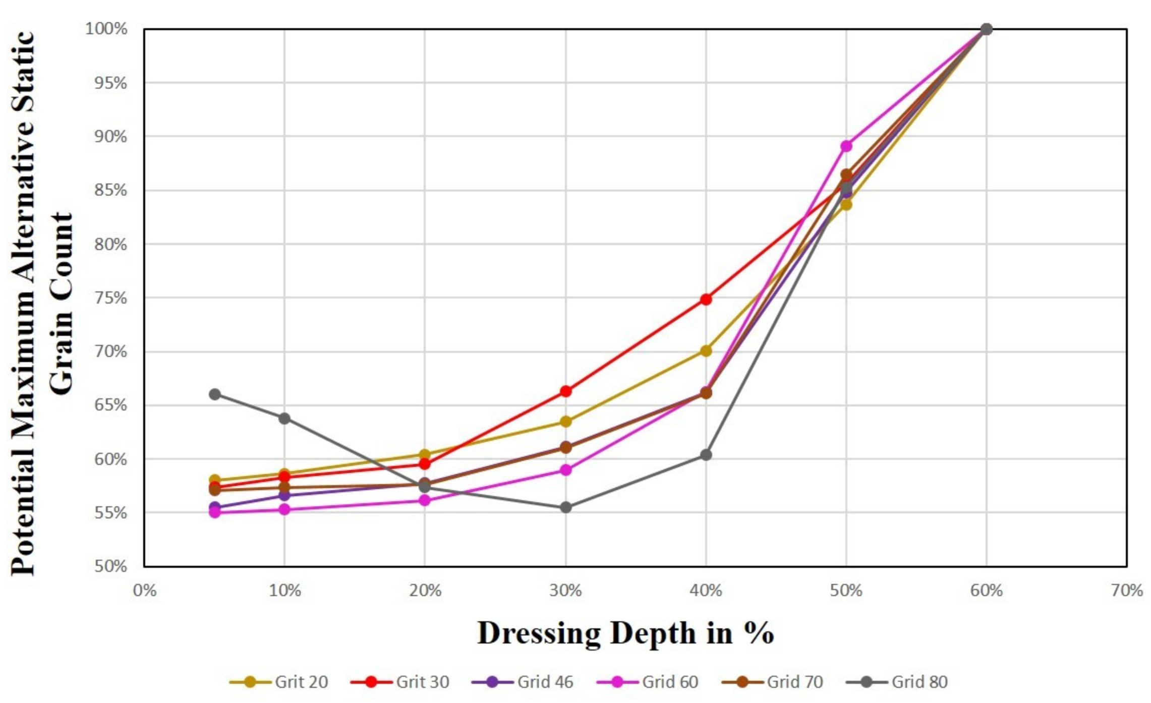
In this section, the variation in alternative static grain count with respect to percentual dressing is investigated. Figure 32 shows that the maximum feasible alternative static grain count increases with the increase in percentage of dressing. All grains show a similar tendency and converge to the potential maximum at 60% dressing depth. A similar explanation as above can be attributed for the higher alternative static grain count with percentual dressing depths. The removal of the top layer of grains exposes a flatter region with a higher static grain count.
From Figure 33, it can be observed that with a fixed dressing depth of 0.1 mm, as the grit size increases (particle size reduces) the potential maximum is reached. For example, grit 80 converges to the potential maximum where the dressing depth is around 60%.

4.3.3. Alternative Protrusion Height

In this section, the variation in alternative protrusion height with respect to the percentual dressing is investigated. The alternative protrusion height reduces with the increase in percentage of dressing depth. From Figure 34, it can be observed that with lower dressing depths, the alternative protrusion heights are closer to the potential maximum. However, when the dressing depth is increased above 30%, there is a decrease in the alternative protrusion height measure. This effect can be attributed to the fact that when the dressing depth is increased, more grits on the top level are removed, which leads to the exposure of lower levels with more tightly packed particles. The outcome is a much smoother surface with lower protrusion heights.
From Figure 35, we observe a similar tendency as in Figure 34. With a fixed dressing depth of 0.1 mm, as the grit size increases (particle size decreases), the maximum feasible alternative protrusion height decreases, e.g., grit 80 measures a lower alternative protrusion height where the dressing depth is around 60%.

4.3.4. Alternative Pore Volume

In this section, the variation in alternative pore volume with respect to percentual dressing is investigated. The alternative pore volume shows a trend similar to that of the alternative protrusion height. From Figure 36, it can be observed that the grits 20–70 initially measure close to the potential maximum and exhibit a decreasing trend for dressing depths greater than 30%. As an exception, for grit 80, an initial increase is observed up to the dressing depth of 30%, after which the alternative pore volume reduces until 60% dressing depth. A similar reason to that of the alternative protrusion height can be attributed here. With the increase in dressing depth, more grits are removed at the top level. This results in the exposure of the lower level of tightly packed grits with far fewer pores.
From Figure 37 we observe a similar tendency as in Figure 36, with a fixed dressing depth of 0.1 mm. As the grit size increases (particle size decreases), the maximum feasible alternative pore volume decreases. For example, grit 80 measures a lower pore volume where the dressing depth is around 60%.

4.3.5. Concluding Remarks and Practical Aspects for Variable Dressing

From the analysis performed on the above measured four output variables, the results with variable dressing depths are comparable to the results with a fixed dressing depth of 0.1 mm [16,18]. The variable dressing depth proves to be advantageous in comparison to the various output parameters for all grit sizes. It also helps to draw a practical conclusion for the manufacturer based on the grinding wheel requirements. For example, if there is a requirement of high bonding strength, high static grain count, high protrusion height, and high pore volume, a recommendation can be made to employ 30% dressing depth to achieve this desired result. It can be concluded that, with the employment of variable dressing, the manufacturer has the freedom to choose an appropriate percentual dressing depth based on the requirement irrespective of the grit size.

4.4. Grinding Wheel Surface

The simulated grinding wheel topographies generated after dressing were analysed based on some input/output variables. The virtual wheel surface computations from Matlab were then visualised using ParaView. An appropriate elevation grid filter was employed to depict a realistic wheel topography of the computed data.

4.4.1. Alternative Protrusion Height

Figure 38 and Figure 39 display the surface topography of grits 20 and 80 with variations in compression levels from 0% to 100% of the maximum possible compression. It is evident that the surface created is unstructured for low percentages of compression (e.g., 0%), and more even structured for higher compression levels. A very even and uniform surface is usually achieved above 50% of maximum compression. It is also visible that with increasing compression, random surface caverns start disappearing, reducing the pore volume of the surface. The surface topography appears to be similar to the previous surface simulations of [16]. The protrusion height increases and particles spread evenly above 50% of maximum compression. On comparing the contour plot for grit 20 and grit 80, it is observed that at maximum compression the particles of grit size 80 are more evenly spread out with fewer visible pores.

4.4.2. Bonding Strength

The bonding force contour plots for grits 20 and 80 are displayed in Figure 40 and Figure 41. For both grit sizes, the characteristic development of the bonding force and the distribution is similar to the analysis of the bonding strength as shown in Section 4.2. The bonding force increases with an increase in compression levels. Although the bonding force distribution is uniform at low compression levels, it is more distinct and visible at high compression levels. For grit 20, at 100% of maximum compression, an area of connected grits is visible that seems to be “melted together”, measuring a high bonding force. This could cause the pore volume to decrease as a result of the bonding material melting further towards the top of the wheel surface. On comparing the contour plot for grit 20 with grit 80 at maximum compression, it is evident that the bonding strength is much higher for grit 20. This due to the fact that a larger grit has a larger neck area with its neighbouring grits, hence resulting in a higher bonding strength.

4.4.3. Dressing Effects on Topography

Figure 42 shows the effect of dressing depth on the alternative protrusion height for grit 20. It can be seen that with an increase in dressing depth, the particle protrusions reduce and the surface is more smooth. This is caused by the removal of top-level particles at higher dressing depths, exposing the lower level, which is more tightly packed. In conclusion, the desired grinding wheel topography with large pore volumes and higher protrusion of grains is achieved at a lower dressing depth between 10%–30%.

4.4.4. Protrusion Height vs. Alternative Protrusion Height

To analyse the functional differences between the grit sizes more precisely, an alternative surface depth measure was introduced in this study. For a better understanding and interpretation, the contour plots of protrusion height and alternative protrusion height are compared in Figure 43. It can be observed that the alternative protrusion height in Figure 43b) is different from the normal protrusion height in Figure 43a) especially for small grit sizes (large particle sizes). Not only are the particles at the top surface considered, but also the area around the centre of the grit. This representation more accurately depicts the real surface for each grit size, as this measure adapts to the respective particle diameter.

4.5. Practical Applications

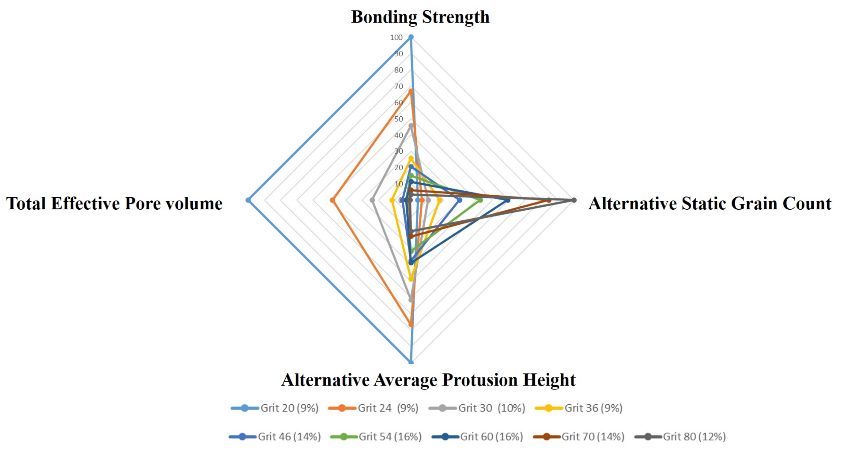
The selection of grit size and compression level is crucial for the grinding performance, which largely depends on four factors: bonding strength, static grain count, protrusion height, and pore volume. While bonding strength and static grain count are for the most part linearly dependent, protrusion height and total pore volume vary in a non-linear fashion. Thus, while selecting grit size and compression level, the requirements need to be clear. The radar chart helps to draw many practical conclusions based on the requirements; see Figure 44. For example, if the requirement is coarse grinding, a suggestion can be made for the use of a small grit size (larger particle size) at maximum compression. Under these circumstances the bonding strength is high, which provides higher endurance; the protrusion height is high, enabling deeper penetration; and the pore volume is high, enabling more abrasive material to fit into the pores. However, the static grain count remains low. On the other hand, if the requirement is fine grinding, a suggestion can be made for the use of a large grit size (lower particle size) at maximum compression. Under these circumstances, a high static grain count results in a smooth surface. However, it has to be noted that the bonding strength, protrusion height, and pore volume are low. Hence, the radar charts can be beneficial to the manufacturers in drawing practical conclusions based on the requirements.

5. Conclusions and Future Work

In this study we have provided a realistic simulation of various stages in the manufacturing process of a grinding wheel, starting from modelling the raw material, particle compression, sintering, and dressing to obtain the final grinding surface. The mixing and compression of the bond and abrasive material were simulated with the DEM software LIGGGHTS. The firing and dressing were simulated using different algorithms in Matlab. The final surface topography was visualised using ParaView. Finally, different output variables were analysed, i.e., bonding strength, alternative static grain count, alternative protrusion height, and effective pore volume, as functions of the manufacturing and dressing parameters.
An increasing percentage of compression was found to increase the bonding strength of particles. Furthermore, the larger the abrasive particles, the higher the bonding strength. The static grain count was found to increase with increasing compression, following a characteristic slope that remained steady at the beginning, then sharply increased and flattened at about 30% of the maximum feasible bonding strength. The smaller the particle size, the higher the static grain count. The protrusion height displayed a characteristic slope that exponentially increased until about 3% of the maximum compression and remained steady afterwards. The protrusion height decreased with decreasing grit size. The effective pore volume remained steady for compression levels above 2% and decreased with decreasing particle size.
The following limitations that were not addressed in the previous studies [16,18] were considered for the simulations performed as part of this study. Firstly, the area of the modelled metal cast was varied according to various grit sizes, enabling a comparison of results for particle sizes. Secondly, two new measures were introduced: (1) the alternative protrusion height shows structural differences between the bondings of different grit sizes and offers an improved comparison of grit sizes. The smaller the particles get, the lower the protrusion height becomes; (2) the total alternative effective pore volume allows a comparison of the pore volume of different particles with respect to their individual bonding surface. It was found that the smaller the particles, the smaller the total alternative effective pore volume. Finally, the dressing depths were set as a variable parameter for different particle sizes, allowing comparable measurements for various parameters.
However, this study also has its own limitations that could be overcome in future. The DEM simulation in this study did not separate the particles into bond material and abrasive grit. Due to this simplification, some of the compression results might be affected. By using different DEM software for the simulation of the particle mixing and compression stages, this potential source of errors could be avoided. The DEM simulation also assumes that the particle along with the bond layer are perfect spheres, which is not the case in reality. An approach of modelling the particles as clumped multi-spheres [39] using the Monte Carlo method to generate granular particle geometries could be used. Alternatively, the modelling of particles as fractal geometries [40] can be employed to obtain granular particle shapes. It was also observed that the simulation was not feasible to obtain realistic grinding wheel topographies of particle sizes smaller than grit 80, requiring further development in this direction.
Although the above mentioned limitations might have affected the results, the general findings remain valid and should be evaluated in empirical studies, using compression as a factor of variation for the grinding wheel manufacturing.

Author Contributions

Conceptualization, P.S.; methodology, P.S.; investigation, P.S.; data curation, D.M.; writing—original draft preparation, P.S.; writing—review and editing, K.M.d.P.; supervision, K.M.d.P. and P.S.; project administration, K.M.d.P.; funding acquisition, K.M.d.P. All authors have read and agreed to the published version of the manuscript.

Funding

This research was funded by the Deutsche Forschungsgemeinschaft (DFG, German Research Foundation) grant number 252408385; IRTG 2057, Physical Modeling for Virtual Manufacturing Systems and Processes.

Data Availability Statement

No data are available but can be provided upon request.

Conflicts of Interest

The authors declare no conflict of interest.

References

  1. Wang, Y.; Li, C.; Zhang, Y.; Yang, M.; Zhang, X.; Zhang, N.; Dai, J. Experimental evaluation on tribological performance of the wheel/workpiece interface in minimum quantity lubrication grinding with different concentrations of Al2O3 nanofluids. J. Clean. Prod. 2017, 142, 3571–3583. [Google Scholar] [CrossRef]
  2. Rubio, E.; Jáuregui-Correa, J. A wavelet approach to estimate the quality of ground parts. J. Appl. Res. Technol. 2012, 10, 28–37. [Google Scholar] [CrossRef]
  3. Rowe, W.B. Principles of Modern Grinding Technology; William Andrew: Norwich, NY, USA, 2013. [Google Scholar]
  4. Marinescu, I.D.; Hitchiner, M.P.; Uhlmann, E.; Rowe, W.B.; Inasaki, I. Handbook of Machining with Grinding Wheels; CRC Press: Boca Raton, FL, USA, 2006. [Google Scholar]
  5. Doman, D.; Warkentin, A.; Bauer, R. A survey of recent grinding wheel topography models. Int. J. Mach. Tools Manuf. 2006, 46, 343–352. [Google Scholar] [CrossRef]
  6. Wegener, K.; Hoffmeister, H.W.; Karpuschewski, B.; Kuster, F.; Hahmann, W.C.; Rabiey, M. Conditioning and monitoring of grinding wheels. CIRP Ann. 2011, 60, 757–777. [Google Scholar] [CrossRef]
  7. Hecker, R.L.; Ramoneda, I.M.; Liang, S.Y. Analysis of wheel topography and grit force for grinding process modeling. J. Manuf. Process. 2003, 5, 13–23. [Google Scholar] [CrossRef]
  8. Barth, S.; Klocke, F. Influence of the grinding wheel topography on the thermo-mechanical stress collective in grinding. Inventions 2017, 2, 34. [Google Scholar] [CrossRef] [Green Version]
  9. Weiß, M.; Klocke, F.; Barth, S.; Rasim, M.; Mattfeld, P. Detailed analysis and description of grinding wheel topographies. J. Manuf. Sci. Eng. 2017, 139. [Google Scholar] [CrossRef]
  10. Osa, J.L.; Sanchez, J.A.; Ortega, N.; Iordanoff, I.; Charles, J.L. Discrete-element modelling of the grinding contact length combining the wheel-body structure and the surface-topography models. Int. J. Mach. Tools Manuf. 2016, 110, 43–54. [Google Scholar] [CrossRef] [Green Version]
  11. Chen, C.; Tang, J.; Chen, H.; Zhu, C. Research about modeling of grinding workpiece surface topography based on real topography of grinding wheel. Int. J. Adv. Manuf. Technol. 2017, 93, 2411–2421. [Google Scholar] [CrossRef]
  12. Liu, W.; Deng, Z.; Shang, Y.; Wan, L. Parametric evaluation and three-dimensional modelling for surface topography of grinding wheel. Int. J. Mech. Sci. 2019, 155, 334–342. [Google Scholar] [CrossRef]
  13. Liao, D.; Shao, W.; Tang, J.; Li, J.; Tao, X. Numerical generation of grinding wheel surfaces based on time series method. Int. J. Adv. Manuf. Technol. 2018, 94, 561–569. [Google Scholar] [CrossRef]
  14. Kang, M.; Zhang, L.; Tang, W. Study on three-dimensional topography modeling of the grinding wheel with image processing techniques. Int. J. Mech. Sci. 2020, 167, 105241. [Google Scholar] [CrossRef]
  15. Gu, Q.; Deng, Z.; Lv, L.; Liu, T.; Teng, H.; Wang, D.; Yuan, J. Prediction research for surface topography of internal grinding based on mechanism and data model. Int. J. Adv. Manuf. Technol. 2021, 113, 821–836. [Google Scholar] [CrossRef]
  16. Li, X. Modeling and simulation of grinding processes based on a virtual wheel model and microscopic interaction analysis. Worcest. Polytech. Inst. 2010, 4, 38–78. [Google Scholar]
  17. Li, X.; Rong, Y.K. Kinematics Simulation of Grinding Process Based on Virtual Wheel Model and Micro-Cutting Analysis. Int. Manufact. Sci. Eng. Conf. 2009, 43611, 341–346. [Google Scholar]
  18. Li, X.; Rong, Y. Framework of grinding process modeling and simulation based on microscopic interaction analysis. Robot. Comput.-Integr. Manuf. 2011, 27, 471–478. [Google Scholar] [CrossRef]
  19. Koshy, P.; Jain, V.; Lal, G. Stochastic simulation approach to modelling diamond wheel topography. Int. J. Mach. Tools Manuf. 1997, 37, 751–761. [Google Scholar] [CrossRef]
  20. Doi, T.; Uhlmann, E.; Marinescu, I.D. Handbook of Ceramics Grinding and Polishing; William Andrew: Norwich, NY, USA, 2015. [Google Scholar]
  21. Marinescu, I.D.; Rowe, W.B.; Dimitrov, B.; Ohmori, H. Tribology of Abrasive Machining Processes; William Andrew: Norwich, NY, USA, 2012. [Google Scholar]
  22. Jain, R.K.; Jain, V. Stochastic simulation of active grain density in abrasive flow machining. J. Mater. Process. Technol. 2004, 152, 17–22. [Google Scholar] [CrossRef]
  23. Li, X.; Wolf, S.; Zhi, G.; Rong, Y.K. The modelling and experimental verification of the grinding wheel topographical properties based on the ‘through-the-process’ method. Int. J. Adv. Manuf. Technol. 2014, 70, 649–659. [Google Scholar] [CrossRef]
  24. Davis, T.D.; DiCorleto, J.; Sheldon, D.; Vecchiarelli, J.; Erkey, C. A route to highly porous grinding wheels by selective extraction of pore inducers with dense carbon dioxide. J. Supercrit. Fluids 2004, 30, 349–358. [Google Scholar] [CrossRef]
  25. Ravuri, B.P.; Goriparthi, B.K.; Revuru, R.S.; Anne, V.G. Performance evaluation of grinding wheels impregnated with graphene nanoplatelets. Int. J. Adv. Manuf. Technol. 2016, 85, 2235–2245. [Google Scholar] [CrossRef]
  26. Bhateja, C.; Lindsay, R. The Importance of Abrasive Grinding Wheel Hardness Control for the Productivity of Production Grinding Operations. CIRP Ann. 1981, 30, 247–249. [Google Scholar] [CrossRef]
  27. Jackson, M.J. A Study of Vitreous-Bonded Abrasive Materials. Ph.D. Thesis, Liverpool John Moores University, Liverpool, UK, 1995. [Google Scholar]
  28. Kirsch, B.; Effgen, C.; Büchel, M.; Aurich, J. Comparison of the embodied energy of a grinding wheel and an end mill. Procedia CIRP 2014, 15, 74–79. [Google Scholar] [CrossRef] [Green Version]
  29. Prasad, M.; Kopycinska, M.; Rabe, U.; Arnold, W. Measurement of Young’s modulus of clay minerals using atomic force acoustic microscopy. Geophys. Res. Lett. 2002, 29, 13. [Google Scholar] [CrossRef]
  30. Zhu, Y.; Liang, S.; Zhan, Z.; Xiao, P.; Fan, Z. Simulation of the change of sintering neck between two grains in two dimensions. Acta Metall. Sin. Engl. Lett. 2006, 19, 397–404. [Google Scholar] [CrossRef]
  31. Bouvard, D.; McMeeking, R. Deformation of interparticle necks by diffusion-controlled creep. J. Am. Ceram. Soc. 1996, 79, 666–672. [Google Scholar] [CrossRef]
  32. Li, M.; Ding, W.; Li, B.; Xu, J. Morphological evolution and grinding performance of vitrified bonded microcrystal alumina abrasive wheel dressed with a single-grit diamond. Ceram. Int. 2019, 45, 19669–19678. [Google Scholar] [CrossRef]
  33. Tawakoli, T.; Rasifard, A. Dressing of grinding wheels. In Machining with Abrasives; Springer: Boston, MA, USA, 2011; pp. 181–244. [Google Scholar]
  34. Karpuschewski, B.; Lierse, T.; Kaul, T.R.; Schulze, S.; Mueller-Cramm, D. Kinematic process model and investigation of grain breakout for conditioning with CVD diamond dressing disks. CIRP J. Manuf. Sci. Technol. 2018, 22, 21–29. [Google Scholar] [CrossRef]
  35. Bergs, T.; Ohlert, M.; Prinz, S.; Barth, S. Modeling of the Fracture Behavior of CBN Grains during Single Grain Dressing using FEM. Procedia CIRP 2020, 93, 1514–1519. [Google Scholar] [CrossRef]
  36. Ding, W.; Linke, B.; Zhu, Y.; Li, Z.; Fu, Y.; Su, H.; Xu, J. Review on monolayer CBN superabrasive wheels for grinding metallic materials. Chin. J. Aeronaut. 2017, 30, 109–134. [Google Scholar] [CrossRef] [Green Version]
  37. Hou, Z.B.; Komanduri, R. On the mechanics of the grinding process–Part I. Stochastic nature of the grinding process. Int. J. Mach. Tools Manuf. 2003, 43, 1579–1593. [Google Scholar] [CrossRef]
  38. Shaw, M.C. Principles of Abrasive Processing; Oxford University Press on Demand: Demand, UK, 1996. [Google Scholar]
  39. Eberhardsteiner, J. Approximation of Objects by Spheres for Multisphere Simulations in DEM. Available online: https://www.researchgate.net/profile/Stefan-Amberger/publication/259693012_Approximation_of_Objects_by_Spheres_for_Multisphere_Simulations_in_DEM/links/0a85e52d59a6ea86f5000000/Approximation-of-Objects-by-Spheres-for-Multisphere-Simulations-in-DEM.pdf (accessed on 30 October 2021).
  40. Mollon, G.; Zhao, J. 3D generation of realistic granular samples based on random fields theory and Fourier shape descriptors. Comput. Meth. Appl. Mech. Eng. 2014, 279, 46–65. [Google Scholar] [CrossRef]
Figure 1. Visualisation of the grinding process, adapted from [2].
Jmmp 05 00121 g001
Figure 2. Example manufacturer coding for grinding wheel C30LV and explanations.
Jmmp 05 00121 g002
Figure 3. Grinding wheel cut-out used for simulation.
Jmmp 05 00121 g003
Figure 4. Simulation process in comparison to manufacturing process; adapted based on [16].
Jmmp 05 00121 g004
Figure 5. Input parameters and output properties of simulation; partly adapted based on [18].
Jmmp 05 00121 g005
Figure 6. Visualisation of particle mixing and packing in LIGGGHTS.
Jmmp 05 00121 g006
Figure 7. Visualisation of bond layer and abrasive grain; adapted from [16].
Jmmp 05 00121 g007
Figure 8. Compression of particles.
Jmmp 05 00121 g008
Figure 9. Development of particle connections and neck radius for compression and firing; adapted from [16].
Jmmp 05 00121 g009
Figure 10. Visualisation of new radius calculation.
Jmmp 05 00121 g010
Figure 11. Visualisation of dressing process.
Jmmp 05 00121 g011
Figure 12. Visualisation of (a) static grain count and (b) protrusion height; partly adapted from [19].
Jmmp 05 00121 g012
Figure 13. Visualisation of effective pore volume; partly adapted from [16].
Jmmp 05 00121 g013
Figure 14. Visualisation of simulated grinding wheel surface.
Jmmp 05 00121 g014
Figure 15. Visualisation of the simulation steps.
Jmmp 05 00121 g015
Figure 16. Distribution of grain size for grit 46.
Jmmp 05 00121 g016
Figure 17. Compression force for different percentages of compression.
Jmmp 05 00121 g017
Figure 18. Average bonding strength of particles for different percentages of compression.
Jmmp 05 00121 g018
Figure 19. Average bonding strength depending on compression for different grit sizes; literature values from [38] (p. 116).
Jmmp 05 00121 g019
Figure 20. Alternative static grain count dependent on different percentages of compression.
Jmmp 05 00121 g020
Figure 21. Alternative static grain count dependent on different percentages of maximum feasible average bonding strength.
Jmmp 05 00121 g021
Figure 22. Alternative average protrusion height dependent on different percentages of compression.
Jmmp 05 00121 g022
Figure 23. Alternative average protrusion height in comparison to the percentage of maximum feasible average bonding strength.
Jmmp 05 00121 g023
Figure 24. Alternative average effective pore volume in comparison to different percentages of compression.
Jmmp 05 00121 g024
Figure 25. Alternative average effective pore volume in comparison to the percentage of maximum feasible average bonding strength.
Jmmp 05 00121 g025
Figure 26. Grinding wheel topography detection platform.
Jmmp 05 00121 g026
Figure 27. Detected 2D surface topography.
Jmmp 05 00121 g027
Figure 28. Detected 3D surface topography.
Jmmp 05 00121 g028
Figure 29. Comparison of simulated static grain count values with measured values from experiments and the literature [23].
Jmmp 05 00121 g029
Figure 30. Comparison of simulated protrusion height values with measured values from experiments and the literature [23].
Jmmp 05 00121 g030
Figure 31. Potential maximum of bonding strength dependent on the percentual dressing depth.
Jmmp 05 00121 g031
Figure 32. Potential maximum of alternative static grain count dependent on the percentual dressing depth.
Jmmp 05 00121 g032
Figure 33. Potential maximum of alternative static grain count dependent on the grit sizes for a fixed dressing depth of 0.1 mm.
Jmmp 05 00121 g033
Figure 34. Potential maximum of alternative protrusion height dependent on the percentual dressing depth.
Jmmp 05 00121 g034
Figure 35. Potential maximum of alternative protrusion height dependent on the grit sizes for a fixed dressing depth of 0.1 mm.
Jmmp 05 00121 g035
Figure 36. Potential maximum of alternative pore volume dependent on the percentual dressing depth.
Jmmp 05 00121 g036
Figure 37. Potential maximum of alternative pore volume dependent on the grit sizes for a fixed dressing depth of 0.1 mm.
Jmmp 05 00121 g037
Figure 38. Grit 20 ( d mean = 0.85 mm) surface topography with alternative protrusion height at 0%, 50%, and 100% maximum compression.
Jmmp 05 00121 g038
Figure 39. Grit 80 ( d mean = 0.165 mm) surface topography with alternative protrusion height at 0%, 50%, and 100% maximum compression.
Jmmp 05 00121 g039
Figure 40. Grit 20 surface topography with bonding force at 0%, 50%, and 100% maximum compression.
Jmmp 05 00121 g040
Figure 41. Grit 80 surface topography with bonding force at 0%, 50%, and 100% maximum compression.
Jmmp 05 00121 g041
Figure 42. Dressing effects on surface topography for 10%, 30%, and 60% percentual dressing of grit 20.
Jmmp 05 00121 g042
Figure 43. Grit 20 surface topography comparsion for (a) protrusion height and (b) alternative protrusion height.
Jmmp 05 00121 g043
Figure 44. Radar chart optimised for maximum bonding strength and alternative static grain count at maximum compression; values in % of the maximum possible value.
Jmmp 05 00121 g044
Table 1. Simulation properties and settings.
Particle Properties
Grain fraction49%
Bond fraction10%
Young’s modulus of grain400 GPa
Young’s modulus of bond6.2 GPa
Poisson’s ratio0.3
Maximum particle compression force 35 N mm 2 5000 PSI
Firing properties
Firing time20 h
Grain-boundary diffusion property290 h
Dressing settings
Wheel diameter250 mm
Wheel speed20 mm/s
Dresser travel speed300 mm/min
Dressing depth10%
Dressing lead0.19 mm
Table 2. Grain sizes and distribution used for simulation.
Grid Size d mean d max d min 95% Confidence Interval
200.850 mm0.938 mm0.762 mm0.0440 mm
240.676 mm0.762 mm0.589 mm0.0432 mm
300.532 mm0.589 mm0.476 mm0.0282 mm
360.415 mm0.476 mm0.354 mm0.0305 mm
460.323 mm0.354 mm0.291 mm0.0157 mm
540.273 mm0.291 mm0.255 mm0.0090 mm
600.233 mm0.255 mm0.211 mm0.0110 mm
700.194 mm0.211 mm0.178 mm0.0082 mm
800.165 mm0.178 mm0.152 mm0.0065 mm
Table 3. Fixed dressing depth of 0.1 mm recalculated in terms of percentual values.
Grit Size d mean in % of Dressing
200.85 mm12%
300.532 mm19%
460.323 mm31%
600.233 mm43%
700.194 mm52%
800.165 mm61%
Publisher’s Note: MDPI stays neutral with regard to jurisdictional claims in published maps and institutional affiliations.