Article

Anticipatory Online Compensation of Tool Deflection Using a Priori Information from Process Planning

Institute of Production Engineering and Machine Tools (IFW), Leibniz Universität Hannover, An der Universität 2, 30823 Garbsen, Germany
*
Author to whom correspondence should be addressed.
J. Manuf. Mater. Process. 2021, 5(3), 90; https://doi.org/10.3390/jmmp5030090
Submission received: 26 May 2021 / Revised: 17 July 2021 / Accepted: 6 August 2021 / Published: 17 August 2021
(This article belongs to the Special Issue Progress in Digital Twin Integration for Smart Machining)

Abstract

:
Removing excess material from build-up welding by milling is a critical step in the repair of blades from aircraft engines. This so-called recontouring is a very challenging machining task. Shape deviations often result from the deflection of tool and workpiece due to process forces. Considering the individuality of repair cases, compensation of those deflections by process force measurement and online tool path adaption is a very suitable method. However, there is one caveat to this reactive approach. Due to causality, a corrective movement, following a force variation, is always delayed by a finite reaction time. At this moment, though, the displacement has already manifested itself as a deviation in the machined surface. To overcome those limitations and to improve compensation beyond the reduction of control delays, this study proposes a novel approach of anticipatory online compensation. Flank-milling experiments with abrupt changes in the tool-workpiece engagement conditions are conducted to investigate the limitations of reactive compensation and to explore the potential of the new anticipatory approach.

1. Introduction

Aircraft engines are completely overhauled at regular intervals (15,000–30,000 operating hours) at great expense, whereby defective parts are repaired or replaced. Even when the aircraft reaches the end of its service life after 25–30 years, the engines are sometimes overhauled and continue to be used [1]. About 50% of the overhaul cost is related to the airfoils and mainly to the replacement of worn blades of the high-pressure turbine, which are heavily stressed during operation [2]. Wear and damage of these blades occur due to thermal, mechanical or chemical influences [3,4]. Due to the large number of blades involved, their complex production and the sophisticated materials used, the repair is both rewarding and extremely challenging at the same time.
The repair procedure for engine blades usually consists of four basic steps that can be carried out using different technologies. In the pre-treatment, grit blasting or chemical stripping processes are used to remove coatings. The following step of material deposit fills local damages by brazing or welding. Excess material is then removed in the recontouring process, for example, by manually guided milling or belt grinding. This determines the final shape and surface topography of the blade. At last, a post-treatment by shot peening or local heat treatment may be used to reduce residual stresses [3]. On the shop floor, these steps are still characterised by lots of manual work. Consequently, the success of repair depends on the training and experience of the individual employee as well as his or her subjective assessment of the component condition [5]. Although automated blade repair has been approached in research (e.g., [6,7,8,9]), it has not been implemented on a large scale yet. Major challenges are the diversity of individual damages and the choice and planning of the respective repair strategy.
A holistic approach for automated blade regeneration is developed in the Collaborative Research Centre (CRC) 871 “Regeneration of Complex Capital Goods”. Besides innovative technologies for the different repair processes, it considers the inspection, process simulation and functional simulation of the blades. Thus, different options for the regeneration of every individual blade can be objectively evaluated beforehand [2]. The interaction of production processes with the associated virtual process planning and evaluation processes is investigated in a real manufacturing environment. In order to ensure consistent data management along the process chain and, in particular, to guarantee the exchange of data between the manufacturing and simulation environments, a virtual workpiece twin was developed that carries all the workpiece-related data [5].
The necessity for individually planned processes will become particularly clear in the case of recontouring, as described in the section below.

1.1. Recontouring by Automated Machining

Since the final geometry of the blade is decisive for the performance of the engine, recontouring is very critical [9]. Automated machining of the multiple curved freeform surfaces with the required shape accuracy and surface properties by ball-end milling is already demanding in series production. However, there are additional challenges for automated recontouring. Each case of damage requires an individual local material build-up and, therefore, also an individual material-removal process. In addition, the entire blade is subject to plastic deformations over its lifetime due to creep [3]. Therefore, not only are the actual geometries before recontouring different but the target geometry must also be reverse-engineered from measurement data for every part [3,10]. Thus, recontouring by automated machining demands an individually planned process for every blade.
While a skilled and experienced worker constantly adapts the manual machining process to compensate for deviations and create smooth transitions, this does not apply to regular machine tools. Modern machine tool axes may follow the planned trajectories with negligible tracking errors due to highly dynamic drive and control systems. Nevertheless, the engagement point of the tool and workpiece is displaced because of the process forces and their deforming effect on every component within the flux of force. Especially, recontouring often requires long cantilevered workpiece clamping and long slender tools to access and machine all areas of the material deposit. These contribute significantly to the overall compliance or deflection and tend to resonate with dynamic forces. This article focuses on contour errors due to static and quasi-static process force components, which have to be minimised in order to successfully recontour the blade. Individual processes (batch size 1) cannot be run iteratively, as is common in series production. Furthermore, the potential for reducing structural compliance (mechanical design, clamping devices, tooling) is already utilised to a great extent. Therefore, advanced methods of process planning and adaptive process control are necessary to cope with force-induced contour deviations.

1.2. Adaptive Machining Approaches for High Geometrical Accuracy

Adaptive machining approaches for enhanced geometrical accuracy can be classified according to their working principle into process force restriction and deflection compensation. The restriction of process forces by adapting the feed rate is straightforward and can be implemented in a simple control loop. The disadvantage, however, is that productivity must be sacrificed for accuracy [11,12]. Furthermore, the reduction of displacement is limited since chip formation is always accompanied by forces, and feed variations are only appropriate within certain limits. In contrast, a deflection compensation accepts the deformation of the components and continuously counteracts the displacement of the engagement point by superimposing a corrective movement. Thus, the shape error can theoretically be completely avoided without any loss of productivity [12].
A further distinction can be made between offline and online implementations based on the adaption cycle. Force restriction and deflection compensation can be applied both offline and online. In the case of offline implementation, the NC code is adapted prior to machining during process planning. This can be completed on the basis of process data from previously machined parts (series production) or iterative optimisation algorithms that utilise detailed machining simulations [11,13]. As repair cases are individual (lot size 1) and underlie variances (e.g., material inhomogeneity due to welding), this a priori information is not reliable for recontouring processes. In contrast, online approaches obtain the latest data from the running process. Therefore, they can make short-term adaptions and react to unpredictable effects such as tool wear or variations in material properties.
Overall, an reactive online deflection compensation is the most promising approach for recontouring, and it has already been investigated for various other areas of application. Usually, the displacement is determined indirectly based on a compliance model and the measured process forces. The compensation movement is carried out either by the NC-axes of the machine tool or by some kind of additional actuators.
However, abrupt changes in the process forces, due to varying feed directions and engagement conditions, are a challenge for the reactive compensation [11]. Brecher et al. and Boujnah have shown that control delays can significantly limit the effect of a reactive deflection compensation when the process forces change suddenly [14,15]. Since the reduction of delays is limited, the only way to overcome this issue is a force prediction. In [16], process forces were measured in a milling test and then used with an adequate forward shift in time for the deflection compensation in a following experiment. Compared to a reactive compensation, the errors at transitions between engagement conditions were significantly reduced, but this is not applicable to single-part machining. Hähn et al. combined a reactive compensation with an offline process simulation in order to reduce errors due to predictable force changes in robot machining [17]. The predicted forces were therefore superimposed on the measured forces depending on the situation. An adaptive generalised predictive control of the process forces in milling has been described by Altintas [18,19]. In order to avoid high peak forces in the case of abrupt changes in the cutting conditions, Stemmler et al. proposed a model predictive control (MPC) approach [19]. In this approach, process forces for a short prediction horizon are calculated online with respect to the predicted engagement conditions. The optimal feed rate setpoint sequence is computed by minimising a cost function. This optimisation repeats every control cycle, with the prediction horizon moving forward step by step. For deflection compensation, a comparable approach is not yet known. Although a short-term force prediction for online compensation was considered in [15], it has not been implemented and researched yet.

1.3. Objective and Approach

This study investigates the limitations of reactive deflection compensation in milling processes with dynamically changing contact conditions. Two approaches utilising different actuators are compared. The compensation movement is either superimposed on the setpoints of a common NC axis or carried out by an electromagnetic guide, which allows highly dynamic short-stroke movements with a significantly shorter response time. Both approaches are implemented on the same machine tool prototype to be compared under identical conditions. Furthermore, a method is proposed that may overcome the limitations of system response delays entirely without compromising the advantages of a reactive online approach. It anticipates required compensation movements based on an online force prediction. The underlying cutting force model uses tool-workpiece-intersection data, which are calculated offline within the individual tool path planning process of the CRC 871. The model parameters (process force coefficients) are identified and updated continuously without any a priori knowledge. For the first implementation and evaluation of this approach, flank milling is considered instead of multi-axis ball-end milling.
The following section introduces the machine tool prototype which forms the technical basis for the following investigations. Afterwards, the considered compensation approaches are developed and discussed in detail. This is followed by a description of the machining experiments and the results.

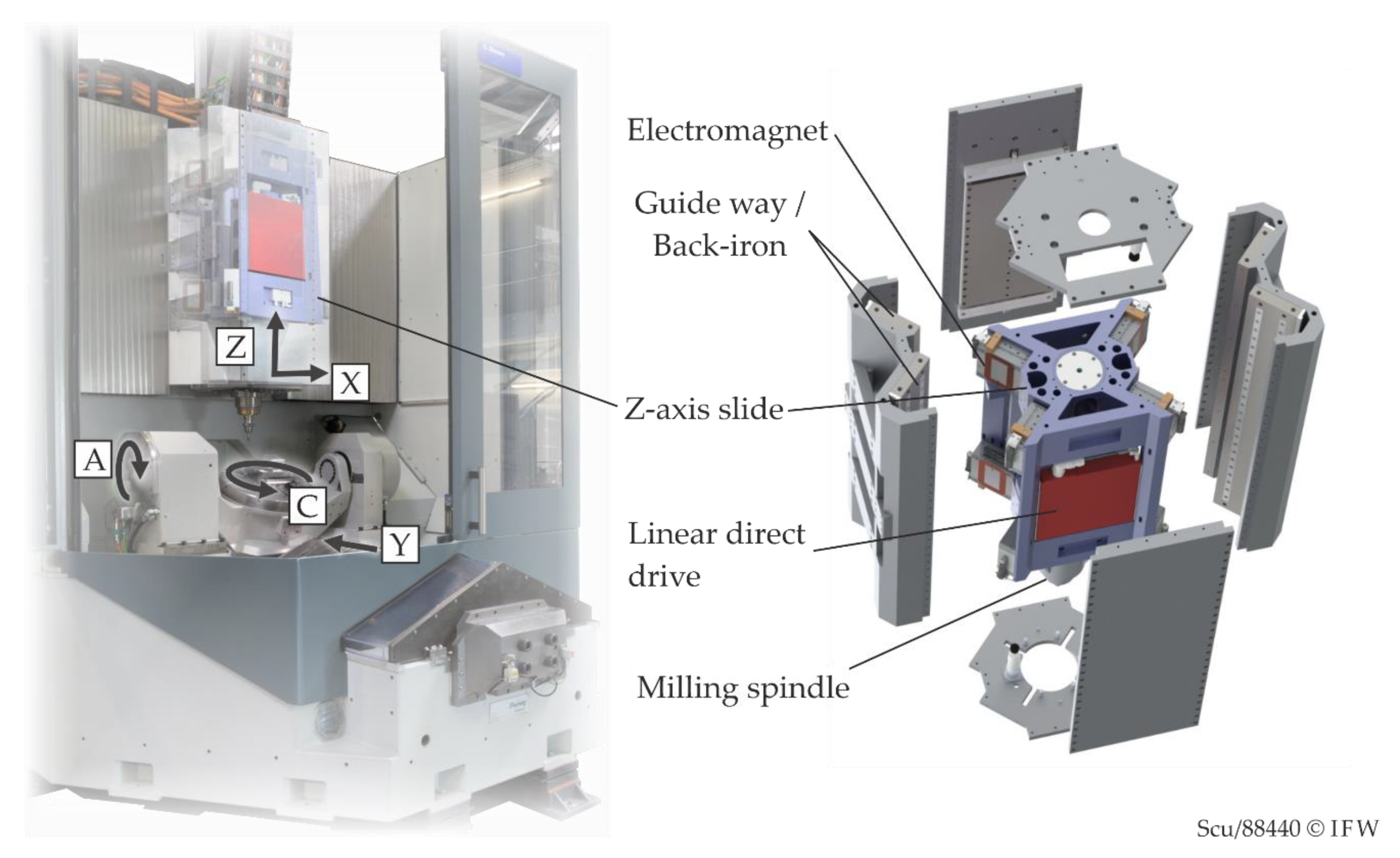
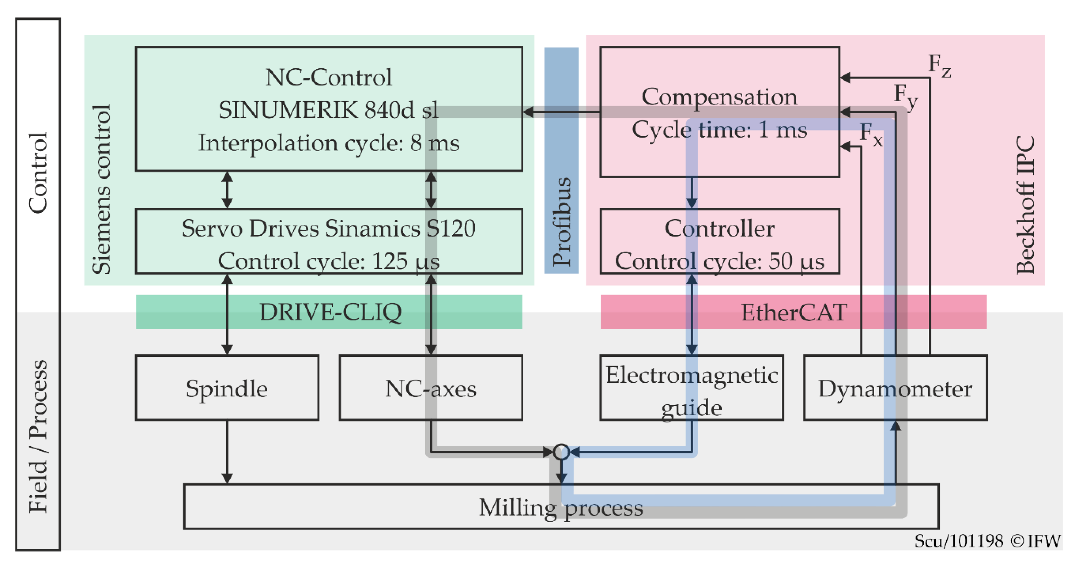
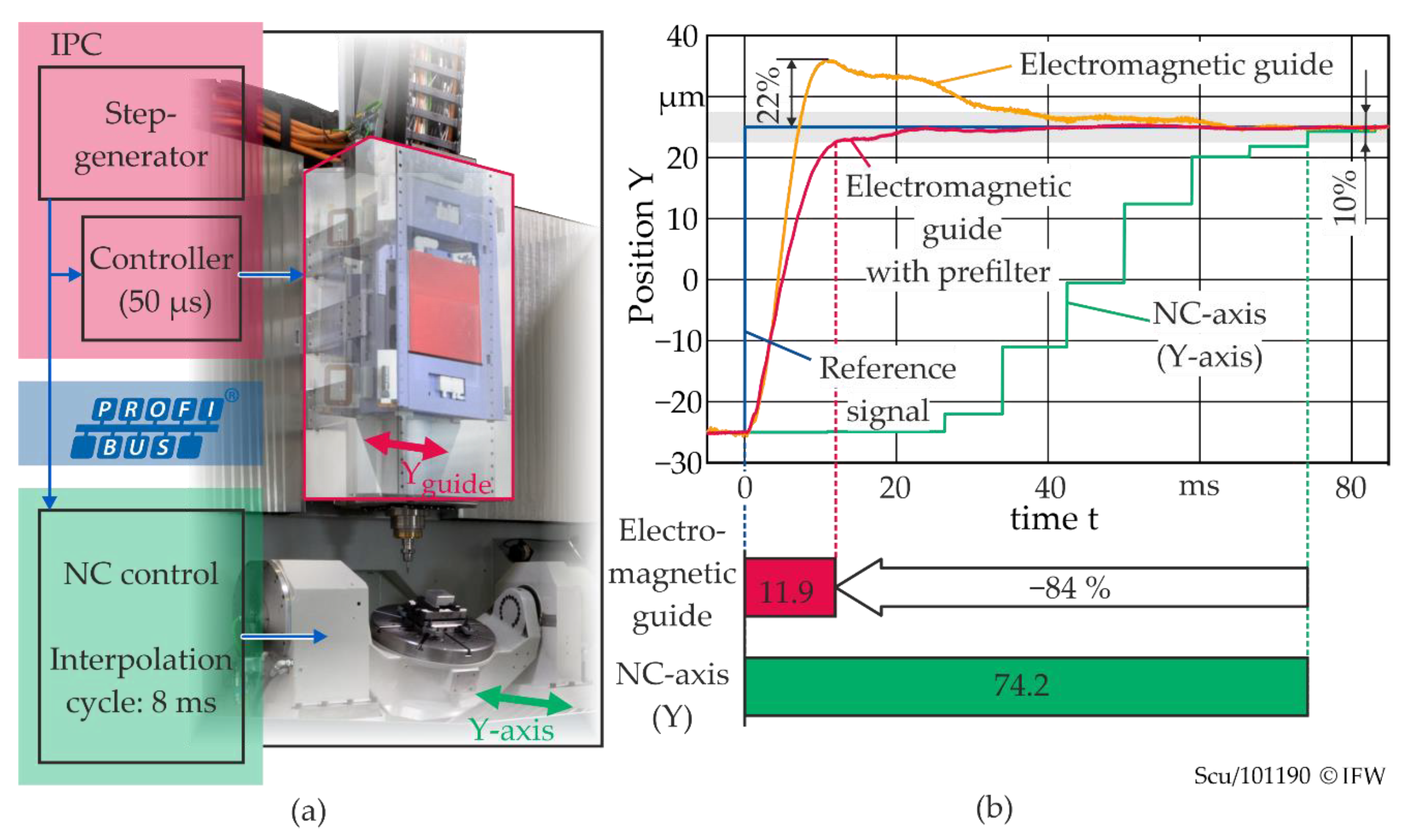
2. Machine Tool Prototype Neximo

2.1. Properties

The “Neximo” (Figure 1) is a five-axis machine tool prototype that is used for the recontouring within the CRC 871. It is fully integrated into the flexible process chain in terms of workpiece handling and data management, as described in Section 1.
On the tool side, the machine kinematics consist of the X-axis, which carries the Z-axis slide and finally, the milling spindle. On the workpiece side, the Y-axis carries a rotary swivel table with the A- and C-axes. All translational axes are driven by direct linear drives, the two rotational axes accordingly by torque motors. A unique technical feature is the Z-axis, which is guided electro-magnetically by eight electromagnets in an O-arrangement. These generate a maximum pulling force of 15 kN each and are equipped with eddy current sensors to determine the distance (air gap) to the back-iron or the guide ways. The position and orientation of the slide are controlled in 5 degrees of freedom by a state-space controller. It is implemented in a Soft PLC (Programmable Logic Controller) on an industrial PC (IPC) from BECKHOFF, running the TwinCAT real-time control environment. The Z-position of the slide, as well as all other NC axes, are controlled by a SIEMENS 840 d sl NC control. Communication between both control environments is established via a field bus connection (Figure 2a). This way, position and state data or setpoints can be exchanged in real-time. However, the sampling rate is limited to the interpolation cycle (IPO) of the NC control. In this case, the IPO amounts 8 ms.
If the slide hovers in a neutral position, the working air gaps are 0.5 mm. With a reference input, the electromagnetic guide is capable of movements in the X–Y plane with a travel of up to 0.2 mm. The relatively low mass of the slide (450 kg) and strong magnets with short force rise times result in a very dynamic command response. Furthermore, direct reference input and the fast control cycle of only 50 μs ensure very short time delays.

2.2. Dynamic Positioning Response

The dynamic response of the actuator system affects the reactive deflection compensation. The following experiment demonstrates the properties of the electromagnetic guide in comparison to the Y-axis of the machine tool. The communication paths and interfaces used here also apply to the compensation approaches in Section 3.
A reference signal is generated on the IPC and then used as an input to both the controller of the magnetic guide and the NC control (Figure 2a). The positions in Y-direction (output) are also recorded on the IPC in order to evaluate the response. The electromagnetic guide setpoint and position values are directly accessible within the current control cycle since its controller is running in the same environment. In the case of the NC axis, the PROFIBUS connection and a synchronous action are used to read and write variables within the NC control. The current axis position is read from the variable actToolBasePos. By setting the variable aaOff, a superimposed position offset is applied. Setting an NC variable from the IPC and obtaining the changed readout of the same variable via PROFIBUS takes 22 ms on average. Assuming that the delay is similar for both directions of communication, a readout delay of 11 ms must be considered for the NC axis.
Figure 2b shows the positioning response for reference steps of 50 µm. Since there is no trajectory planning for the electromagnetic guide, the step response shows a peak overshoot of 11 µm or 22%. This can be completely avoided by using a prefilter that approximates the inverse behaviour of the closed control loop and generates a suitable setpoint sequence. Given a ±5% error band, the electromagnetic guide with prefilter shows a settling time of 11.9 ms. The step response of the Y-axis has already been corrected by the readout delay in this plot. In comparison to the guide, it shows a settling time of 76 ms, which is more than six times longer. This obviously has two reasons. On the one hand, the ascent is less steep. This means that the axis does not reach the same average speed due to restrictions in acceleration and jerk. On the other hand, there is a significant delay of more than 20 ms before the position signal follows the input signal at all. This delay results from the communication between IPC and NC control and from signal processing and interpolation inside the NC control.

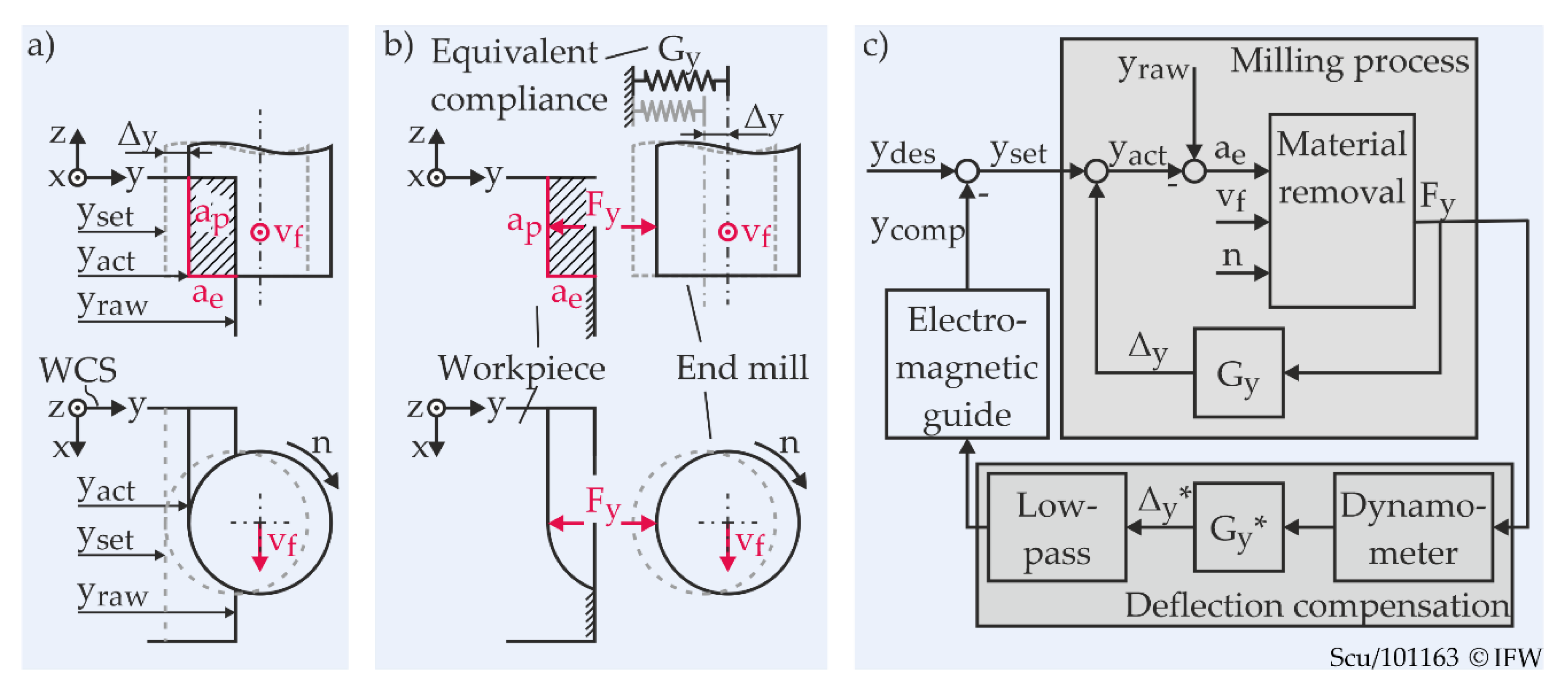
3. Deflection Compensation

In this section, the reactive deflection compensation and its implementation on the control system of the Neximo are described. This is followed by the presentation of the novel anticipatory compensation approach and its implementation.

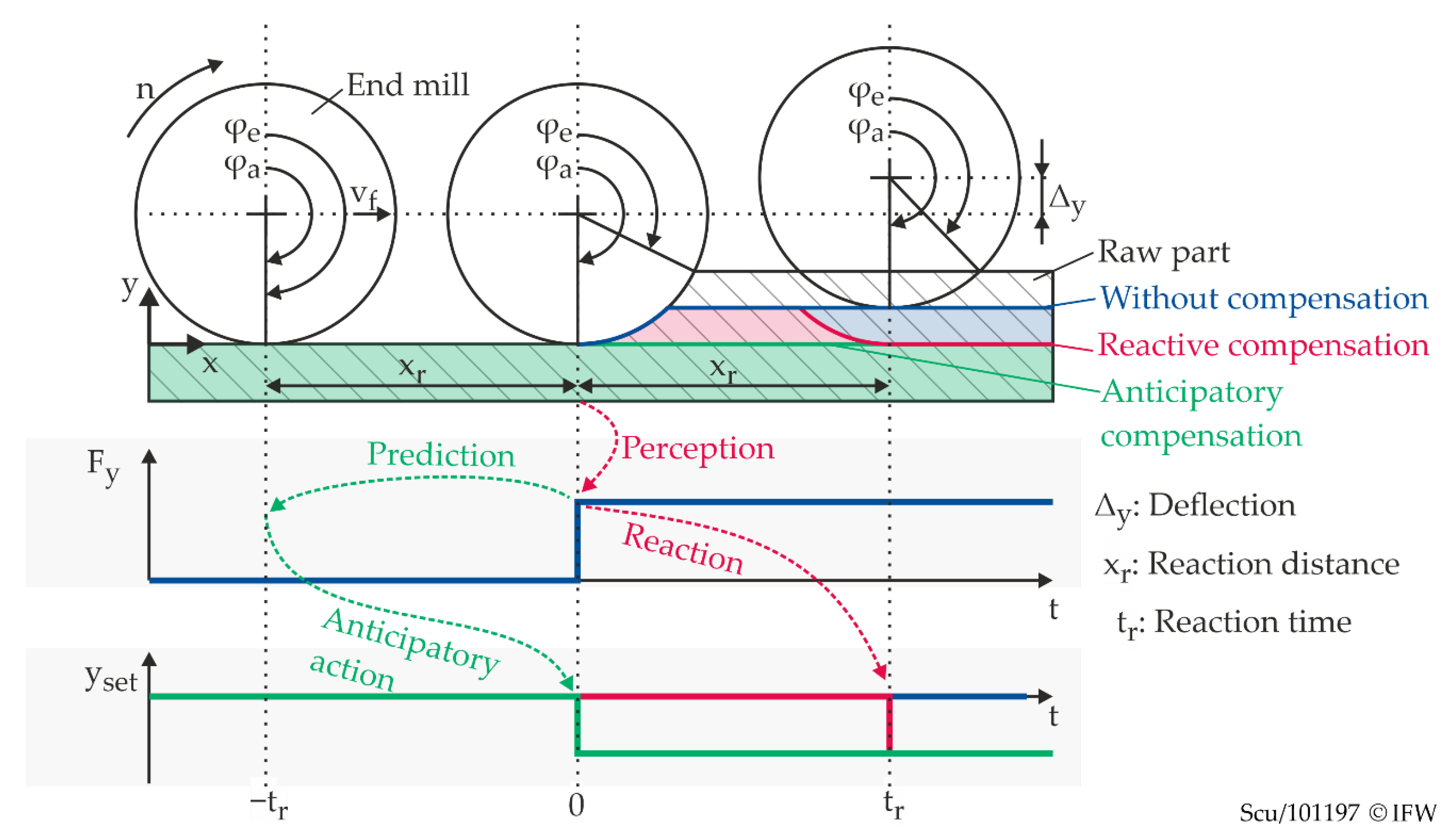
3.1. Reactive Deflection Compensation

In the flank-milling process depicted in Figure 3a, the relative displacement Δy between tool and workpiece in the y-direction of the workpiece coordinate system (WCS) directly affects the shape accuracy of the generated contour. This displacement Δy depends solely on the feed normal force Fy and the total compliance of all components within the flux of force. A single substitute compliance Gy represents the relationship between force and displacement of the milling tool in Figure 3b. This allows the milling process to be modelled in a simplified way, as shown in Figure 3c. The inner feedback loop includes a representation of the material removal and the compliance Gy. Assuming a constant feed rate vf and spindle speed n, the feed normal force Fy only depends on the actual width of cut ae. The width of cut is the difference between the raw workpiece contour yraw and the actual contour point at yact that is generated at the given moment. In contrast to the depiction in Figure 3, the raw workpiece contour changes dynamically along the tool path. The trajectory yset is set by the NC control and tracked by the NC axes. At the summation point, yset is superimposed with the displacement Δy, and the actual contour yact is obtained.
The simple aim of a deflection compensation is to continuously correct the trajectory yset by a compensation offset ycomp so that the actual contour yact equals the desired contour ydes (Figure 3c). This is obviously true when ycomp equals Δy. The outer loop in Figure 3c shows the basic structure of a reactive deflection compensation using the electromagnetic guide. It consists of a force measuring device (dynamometer) and a compliance model G y * . A low pass filter has to be added to prevent periodic force components from being fed back into the process via the actuator and inducing vibrations or surface defects. Obviously, compensation of the deflection is only achievable to a limited extent due to the transient response of the feedback path as well as deviations between the compliance model and the real system.
The implementation of the reactive deflection compensation within the control system of the machine tool is demonstrated in Figure 4. It is divided horizontally into a control layer and a field or process and shows the information flow between the components of the control system and the hardware. Furthermore, basic information about the communication paths and cycle times is given.
A Kistler 9257B dynamometer is used for force measurement. The signals of the dynamometer are processed by a charge amplifier (Kistler 5015a). The analogue output signals are captured by an AD-Converter (BECKHOFF EL3702) at a sample rate of 20 kHz and are then transferred to the BECKHOFF IPC via EtherCAT. The calculation of the compensation setpoint, based on the compliance, takes place on the IPC within a PLC cycle of 50 µs. For compensation by means of the NC axis, the actual setpoint is then transferred to the NC control via PROFIBUS as described in Section 1.2. There, it is superimposed to the Y-axis position within the interpolator. Alternatively, if the compensation is carried out by the electromagnetic guide, the compensation setpoint is directly used as a reference input for the state-space controller. In order to evaluate the effects of the different positioning behaviour on the compensation quality, both options are investigated experimentally in Section 5.

3.2. Anticipatory Deflection Compensation

The reactive compensation described in the previous section is subject to delays because of signal and bus runtimes as well as processing cycles. This means that the system cannot react to process force variations before a reaction time tr has elapsed. The effect is shown in simplified form in Figure 5 (red curves and arrows) without considering any positioning dynamics. In this scenario, the milling tool moves from an area where it barely touches the surface to an area with a substantial width of cut. The transition occurs at the time t = 0, as depicted in the upper graph in Figure 5. The radius in the transition area of the prepared workpiece blank exactly equals the tool radius. This, in theory, leads to an abrupt increase of the cutting force since the entry angle φe of the cutting edge and, therefore, the average chip cross-section, show a step change. The resulting deflection of the tool is not compensated until the machine tool carries out the corrective movement at t = tr. The surface generated in the meantime consequently deviates from the desired contour.
The contour error and its spatial dimension can be reduced by shorter reaction times, but they can never be completely avoided. To overcome this limitation, future process forces have to be predicted and used to calculate compensation movements that prevent these contour errors. According to the definition proposed by Butz et al., this can be described as an anticipatory behaviour [20]. The time sequence for anticipatory compensation is also shown in Figure 5 (green curves and arrows). Since the anticipatory action is initiated at t = −tr, the compensation motion is executed simultaneously with the increase in force. Hence, the contour error is avoided entirely.
This simplified example shows that anticipatory online compensation requires future process forces for a time horizon which covers at least the reaction time of the system. In order to achieve this, the familiar control system architecture from Figure 4 has been extended in Figure 6. It now includes an additional layer for offline planning and shows a block for process-force prediction in the BECKHOFF TwinCAT environment. This block represents a PLC program that calculates future process forces for an arbitrary prediction horizon, using online and offline data together. The entire procedure can be broken down into the following steps or functions:
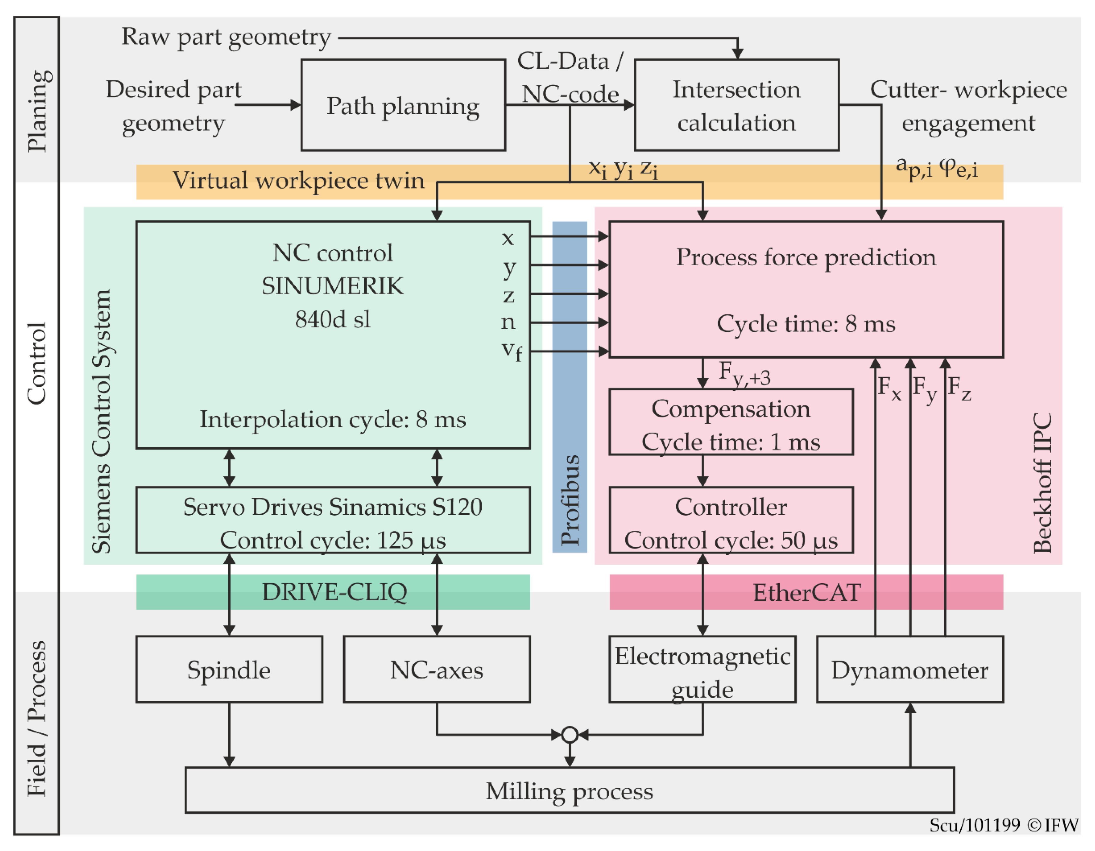
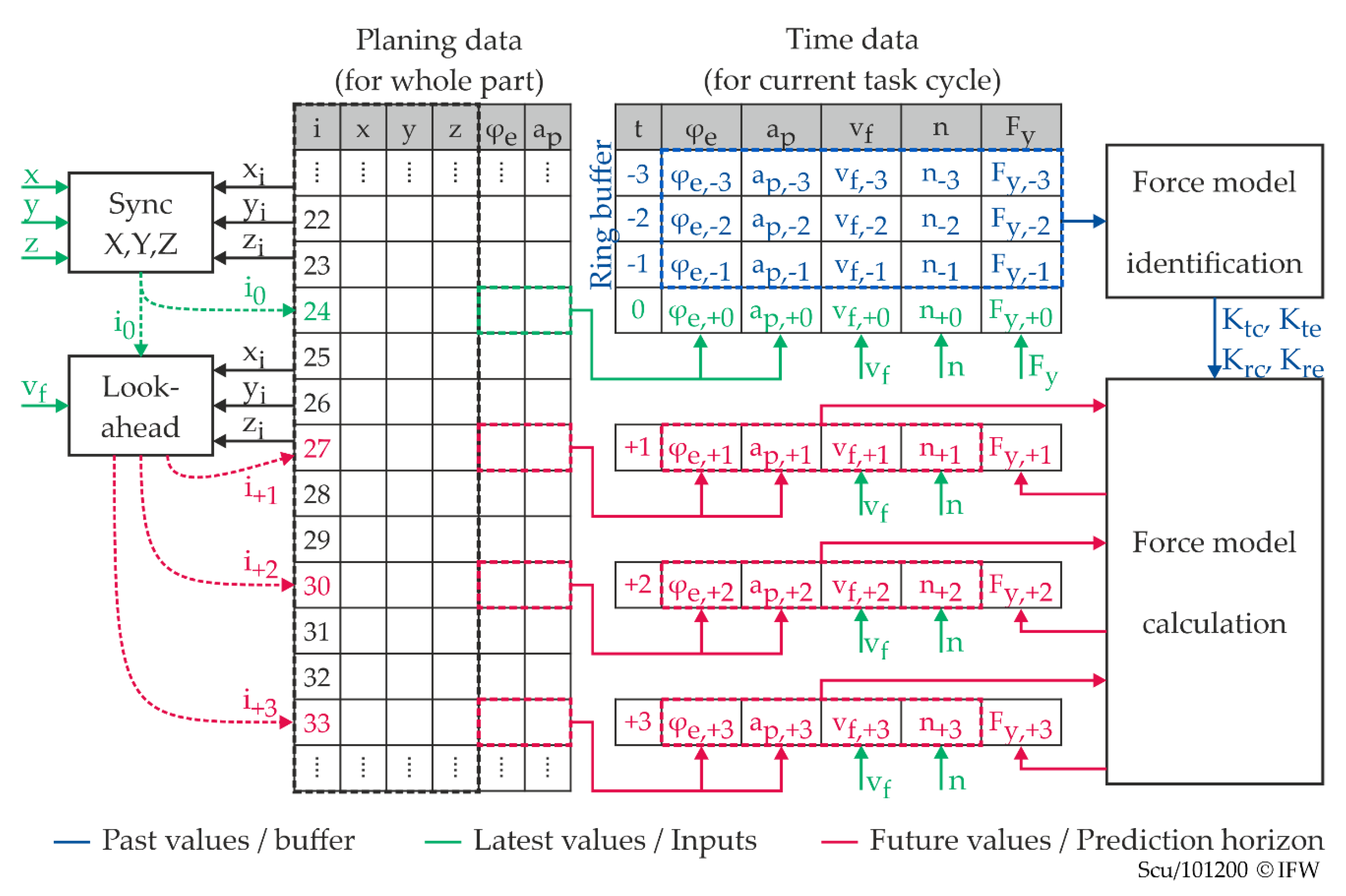
  • The infrastructure of the CRC 871 provides geometry data of each blade after welding, which are then used offline for an individual path planning and NC code generation process. This also includes tool-workpiece-intersection calculations. The virtual workpiece twin then contains all these data.
  • Before machining, the process force prediction initially loads the planned tool path in the form of WCS-coordinates (xi, yi, zi) together with the calculated engagement conditions (depth of cut ap, entry angle φe of the cutting edge) from the virtual workpiece twin.
  • At runtime, the process force prediction receives the latest cutter positions and process parameters from the NC control. The planned tool path data are synchronised with these values and extrapolated into the future within the prediction horizon.
  • The corresponding future engagement conditions are then used to calculate process forces based on a suitable process force model. The output value may, for example, be a force value Fy, +3, which corresponds to the force prediction for a point in time that lies 3 ms in the future.
  • The further application of this force value corresponds exactly to the reactive compensation, as described in the previous section.
The force prediction program executes steps 3 and 4 in an 8 ms cycle since the position data from the NC control are also updated every 8 ms. Within the prediction horizon, however, the time resolution of the calculated values is set to 1 ms according to the cycle time of the compensation program. By buffering, it receives a new value every time it is executed.
Figure 7 visualises the processes within the force prediction block in more detail. At first, the planning data are stored in an array without any temporal reference (table to the left). A temporal relation is then established by the synchronisation and the lookahead function as follows. First, a least-squares approach determines the row i0 that corresponds best to the latest WCS position of the milling cutter. The engagement conditions of this line can thus be added to the time data (table to the right) for the current state (t = 0 ms). Starting from the current line i0 and using the current feed rate, the distance travelled along the planned path is extrapolated in 1 ms steps by the lookahead function. The corresponding engagement conditions from the lines i+1, i+2, … are also transferred to the time data table. Assuming that the process parameters stay constant within the short horizon of prediction, the time data table is supplemented with the current feed rate vf and spindle speed n.
While the normal feed force for the current line of time data (t = 0 ms) is known from the latest measurement value Fy, the future force values have to be calculated from the data within the time-data table. A semi-empirical process force model, according to Altintas, is used for this [18]. It requires information about the cross-section and the width of the undeformed chip, which in turn result from the process parameters and the engagement conditions. For flank-milling processes, the axial depth of cut ap, the entry angle φe and the exit angle φa of the cutting edge are sufficient to describe the engagement conditions. Furthermore, for down milling of straight contours, the exit angle φa is always π. All other influences (material, cutting edge geometry, contact conditions) are implicitly accounted for in the cutting force coefficients (Ktc, Kte, Krc, Kre) of the model. The basic formulation of the model is given by
( F x F y ) = z 2 π ( sin ( φ e ) sin ( φ a ) cos ( φ a ) cos ( φ e ) cos ( φ e ) cos ( φ a ) sin ( φ e ) sin ( φ a ) ) · ( K t c K t e K r c K r e ) · ( a p   ·   h m a p ) .
In this, Fx and Fy are the process forces in the x- and y-direction of the WCS averaged over one cutter revolution. The number of cutting edges is given by z, and the average uncut chip thickness hm can be substituted by
h m = f z c o s ( φ e ) c o s ( φ a ) φ a φ e .
At the end of each force prediction cycle, the most recent time data, including the measured process forces, are moved into a ring buffer (Figure 7). These data are used to calculate and update the process force coefficients K for the Altintas model. Since the force coefficients are determined continuously during machining, no extra experiments need to be carried out in advance.

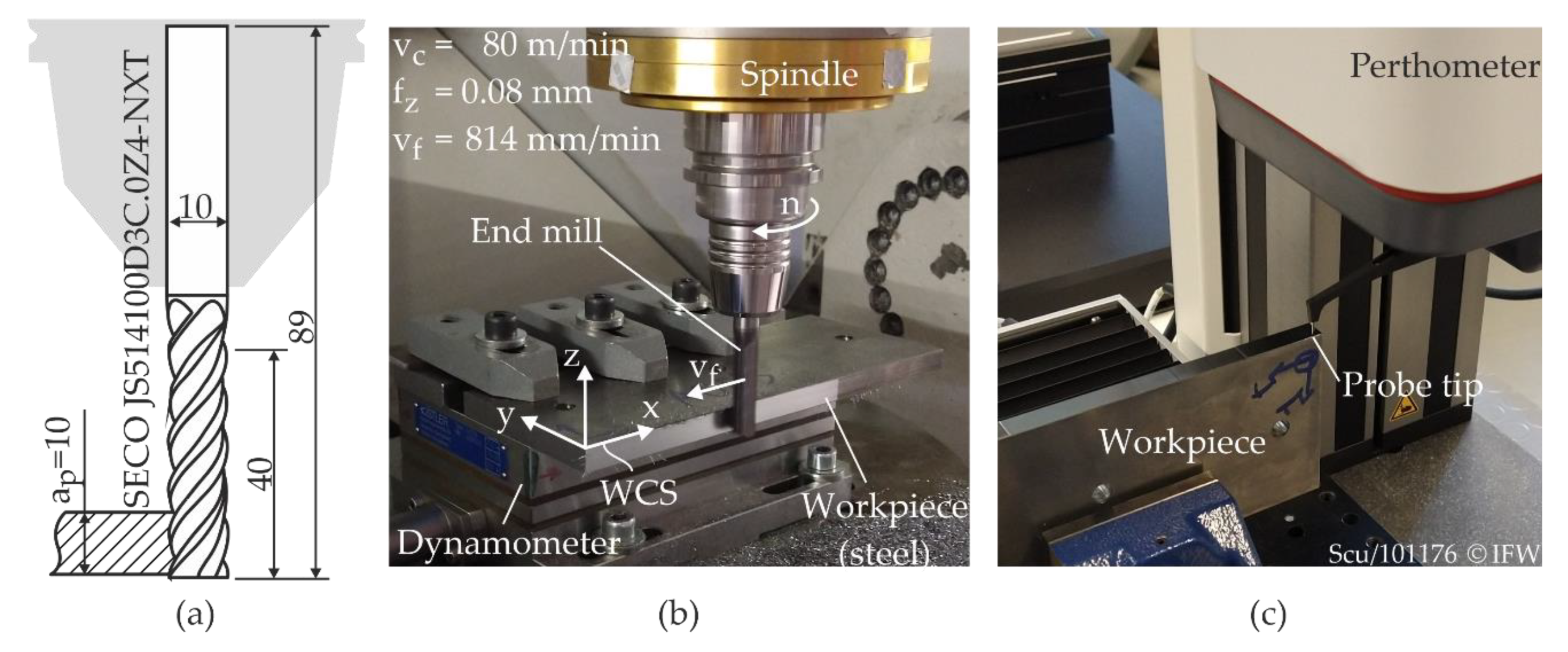
4. Experimental Setup
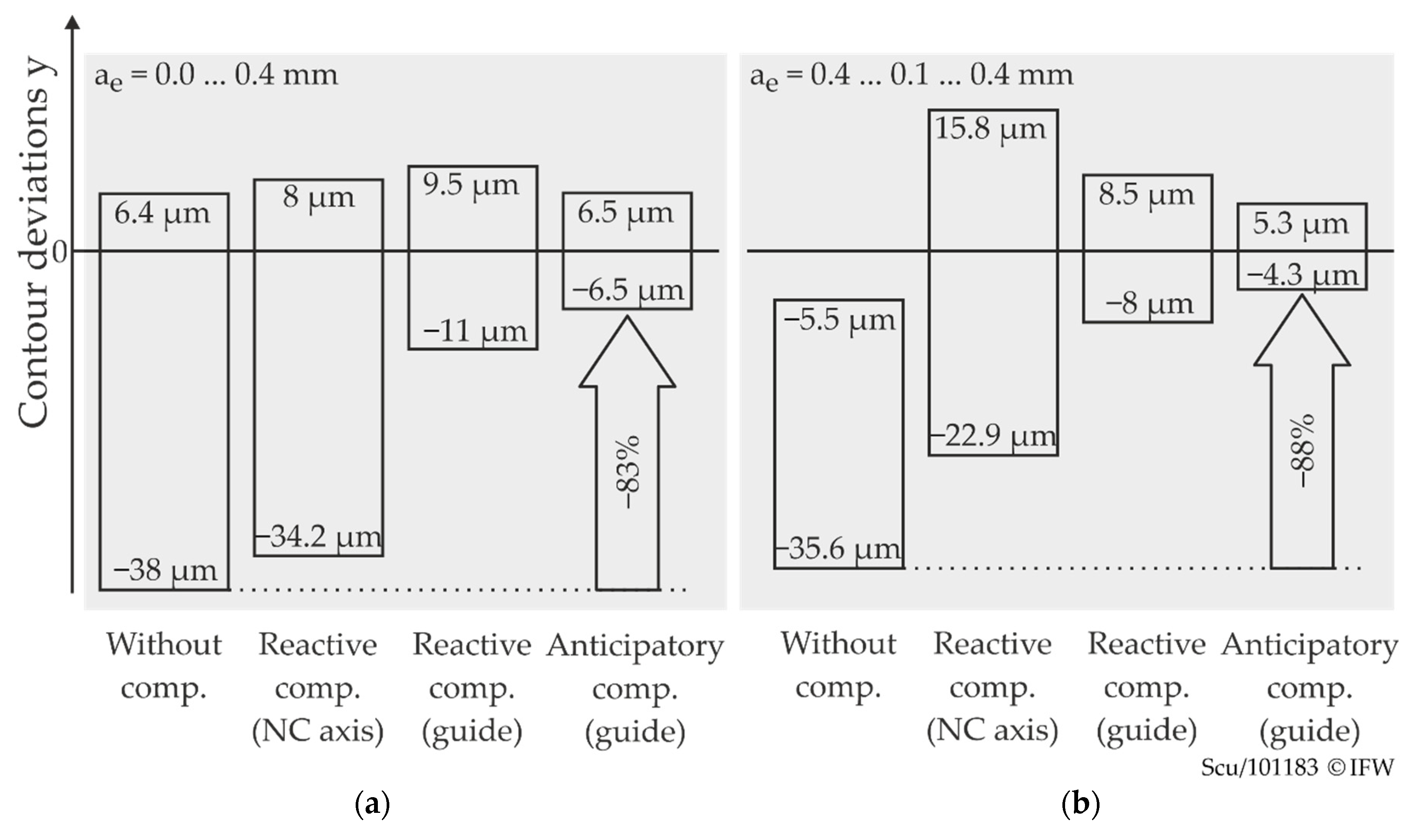
The compensation approaches were investigated in flank milling of straight contours with a varying width of cut. A carbide end mill from SECO with a diameter of 10 mm and 4 flutes was used (Figure 8a). The workpiece was a 10 mm thick piece of cold-rolled steel (C45). During machining, it was clamped directly onto the dynamometer (Kistler 9257B), as seen in Figure 8b.
The experimental procedure involved three steps. First, the workpiece was prepared with the initial contour. A second finishing cut, without resetting the depth of cut, reduced form errors due to deflection and ensured defined, repeatable starting conditions. Both cuts were carried out without any compensation. After preparation, the Workpiece-Coordinate-System (WCS) lay on the corner of the workpiece, and its x-direction was parallel to the X-axis of the machine tool (Figure 8b). The experiment was then carried out in the same setup and clamping situation. The tool described a straight path of 130 mm length along the negative x-direction carrying out a peripheral down milling operation. After that, only the areas at the beginning and end of the path were finished carefully by a second cut. Thus, two reference surfaces with very little error due to deflection were generated. In the last step, the contour was measured on a mahr LD130 perthometer (Figure 8c), which features a vertical resolution of 0.8 nm and form deviations in the scanning axis of less than 100 nm. The residual noise is below 20 nm. It allows a maximum scan path of 130 mm and can therefore measure the entire machined contour, including the reference surfaces, in one scan. Thus, the measured contour y could be evaluated in relation to the reference surfaces.
In order to minimise the effects of model deviations and to fully concentrate on the transient behaviour of the compensation approaches, no sophisticated compliance model was used. Instead, the equivalent compliance G y * was determined within a machining investigation in the same setup as the experiments. For this purpose, the width of cut was increased step by step from 0 mm to 0.8 mm. The step size was 0.08 mm.
Figure 9a shows the actual contour y, measured in the centre of the machined surface at z = −5 mm, and the corresponding normal feed force. Both are plotted over the tool position in WCS x-direction. The feed direction was in the negative x-direction. The desired contour ydes is given above the plots for each area. The effective displacement Δy can now be calculated for each area as the difference between the measured contour y and the desired contour ydes. This is shown for two steps on a larger scale in Figure 9b. The measured values marked in red are approximately in the middle of the single steps. Here, the transient processes are over, and stationary behaviour can be assumed. These values are averaged and used to calculate static equivalent compliance for each step i with
G y , i * = Δ ¯ i F ¯ y , i
Averaged over all steps, the static equivalent compliance in the y-direction for this setup is G y * = 0.283 µm/N.

5. Results

Based on the experimental procedure and setup (Section 4), machining experiments were conducted with each of the compensation methods presented. The spindle speed was 2546 min−1, resulting in a cutting speed of 80 m/min. With the feed per tooth of 0.08 mm, this gives a feed rate of 814 mm/min. The spindle rotation frequency was 42.4 Hz. To suppress the effects of periodic excitation on the surface, the cut-off frequency of the low-pass filter for the reactive compensation was set to 30 Hz.
The prepared contour contained several steps of different heights. In the following, a change in the width of cut ae from 0 mm (cutter touches the contour) to 0.4 mm, as well as a transition from 0.4 mm to 0.1 mm and back to 0.4 mm, will be considered in detail. The transitions are shown qualitatively in the pictograms above the plotted graphs in Figure 10a,b. In the first case, the entry angle φe of the cutting edge and therefore the average chip cross-section abruptly increase at the transition, and an abrupt change in the cutting force occurs. In the second case, the entry angle and the cutting force increase more slowly in the transition zone. The results are presented and discussed on the basis of the measured contour data. The contour plots are displayed according to the WCS. If the tool is engaged, it is deflected in the negative y-direction. Negative y-values, therefore, mean an oversize; positive values indicate an undersize of the workpiece. In all the plots of the contour measurements, the milling tool was added to the ideal path according to the scale. This makes the distorted representation due to unequal scaled axes easier to interpret.

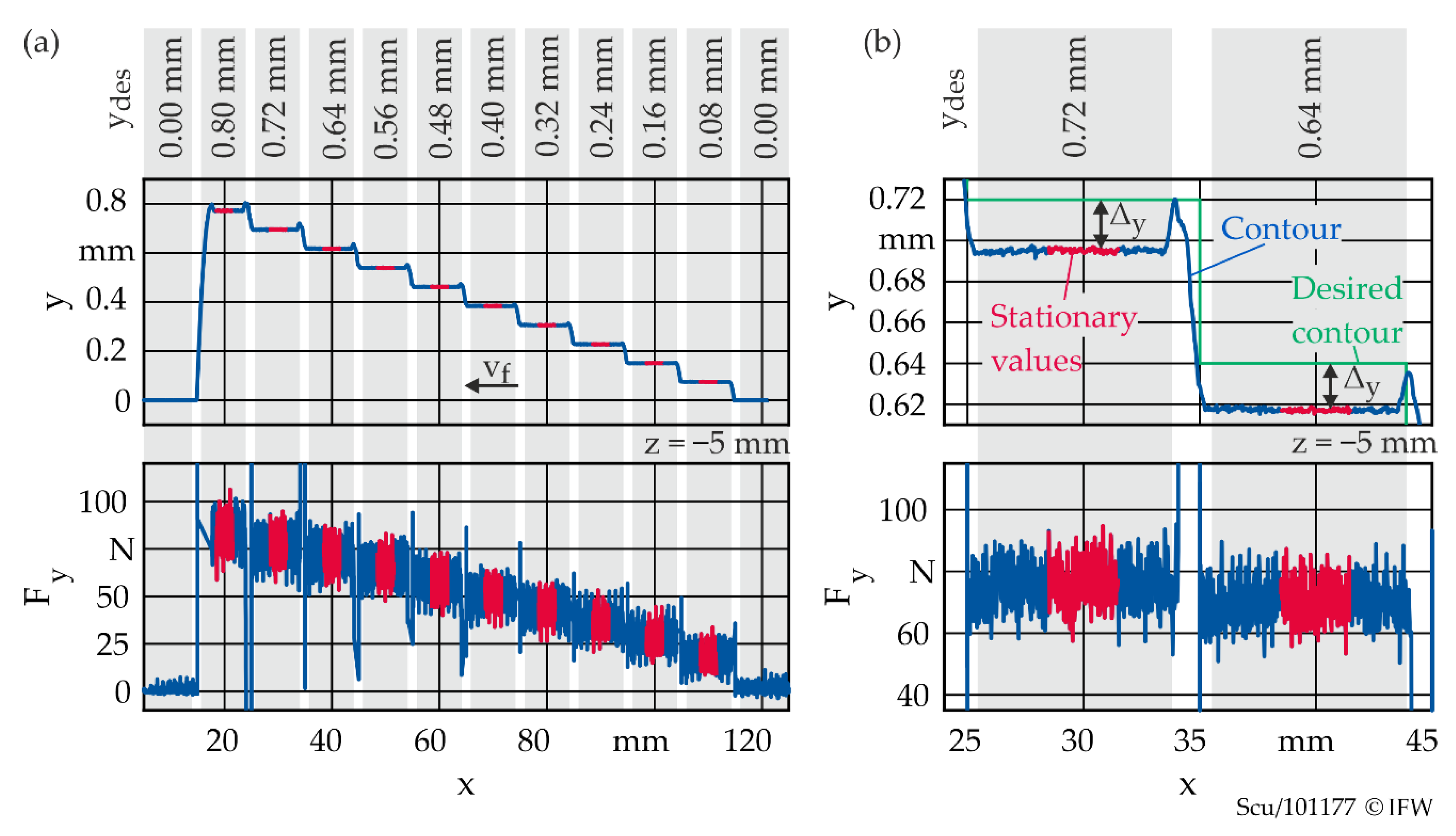
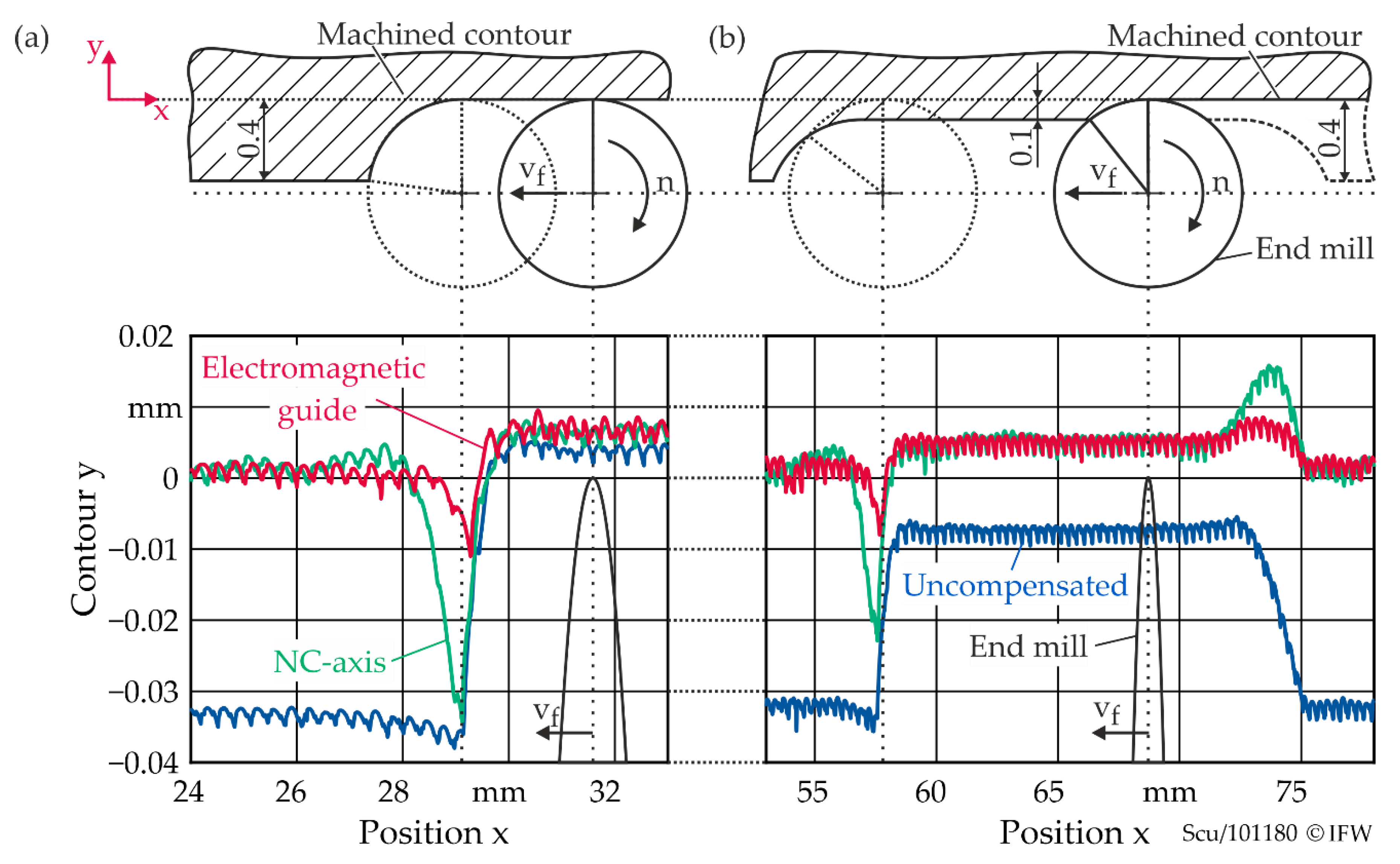
5.1. Reactive Deflection Compensation

The results of the reactive compensation are shown in Figure 10. A reference test without compensation was carried out at first. At the transition from ae = 0 to 0.4 mm (Figure 10a), the contour error increases significantly without compensation, as expected. The maximum deviation results in an oversize of 38 µm. The reactive compensation by means of the NC axis compensates the deflection almost completely after settling, but in the transition zone, the error can only be reduced slightly to 34.2 µm. Here, the compensation movement is carried out too late, when the tool has already almost reached its maximum deflection. In contrast, the correction movement of the magnetic guide takes effect well before the maximum displacement is reached. In this case, the maximum contour deviation is 11 µm, which corresponds to a reduction of 71%.
The transition from ae = 0.1 mm to 0.4 mm (Figure 10b) shows similar behaviour. Since the increase in force is somewhat gentler here, the reactive compensation by means of the NC axis is also more effective. Compared to the uncompensated maximum contour error of approximately 36 µm, a reduction to 23 µm is achieved. Nevertheless, the compensation based on the electromagnetic guide reveals a deviation of only 8 µm.
Figure 10b also shows an undersize at the transition to the lower width of the cut since the compensation movement is not retracted quickly enough. The error is 16 µm for the NC axis and 9 µm for the electromagnetic guide. Due to this overcompensation, the peak-to-peak contour error for compensation using the NC axis is even worse than machining without any compensation.

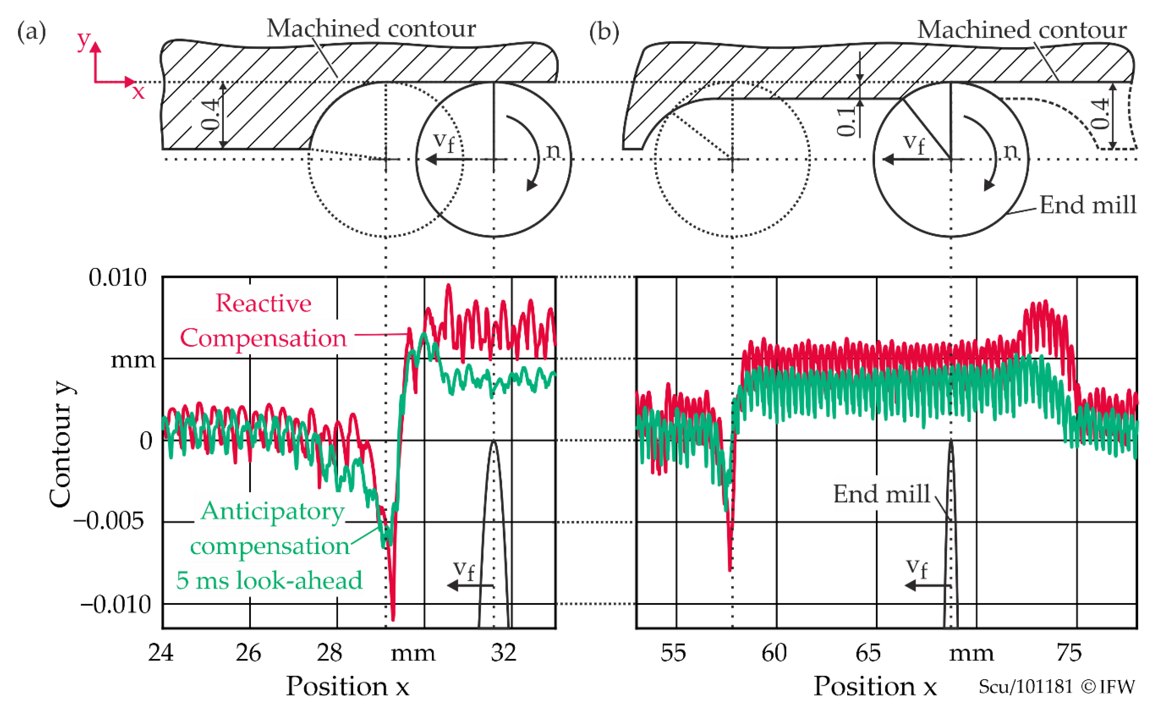
5.2. Anticipatory Deflection Compensation

Figure 11 compares the reactive compensation by means of the electromagnetic guide with the anticipatory approach. For this purpose, a constant lookahead of 5 ms was used, which was determined iteratively. All parameters correspond to the previous investigations. In the transition from ae = 0 mm to 0.4 mm (Figure 11a), the anticipatory approach reduces the maximum contour error from 11 µm to 6.5 µm compared to the reactive approach. In relation to the reference test without compensation, the maximum error is thus reduced by 83%. At the transition from ae = 0.1 mm to 0.4 mm (Figure 11b), the contour deviation is again significantly reduced. The maximum remaining oversize of 4.3 µm is only approximately 12% of the uncompensated error. The overcompensation at the transition to the smaller width of the cut is significantly reduced. Compared to the 8.5 µm with reactive compensation, it is now only 5.3 µm.
The results of the conducted milling experiments are summarised in Figure 12. It shows the maximum and minimum values of the contour deviations from Figure 10 and Figure 11 in comparison.

6. Conclusions and Outlook

Considering the challenges of recontouring, reactive online compensation of deflection has many advantages over other adaptive machining approaches. In recontouring, reacting to unpredictable influences is mandatory due to variances from upstream repair processes or from the repair component itself. Reactive compensation can theoretically avoid contour errors caused by static force components completely without any loss of productivity. Furthermore, it does not affect the machining workflow or limit flexibility regarding the process setup. Arbitrary adjustments of the feed or spindle override by the machine operator, for example, do not compromise the compensation since it is based on real-time force measurements. Despite these advantages, there is one caveat to reactive compensation. Since it is a causal process with a finite reaction time, corrective movement can only take place after a change in force has been detected. At this moment, though, the displacement between tool and workpiece has already manifested itself as an error in the machined surface. These errors become significant in case of abrupt changes of the cutter engagement and depend strongly on the reactivity of the compensation or control loop.
The electromagnetic guide offers higher performance in comparison to the NC axis for those highly dynamic compensation movements. In the milling scenarios considered here, the results far exceeded those of the NC axis. Nevertheless, contour errors still remain in the areas of abrupt transitions. The new anticipatory approach was able to reduce these errors even more, by up to 88%. The proposed method does not further limit flexibility, and it uses data that are generated in the upstream process planning of the CRC 871. Therefore, it could complement a reactive compensation in order to enhance performance for abrupt but predictable changes. However, there are still significant challenges to be overcome. The new method is implemented for three-axis machining. In processes with extensive acceleration and deceleration phases, however, the synchronisation of the planning data reaches its limits. The same applies to five-axis machining with complex tool paths. Here, further data from the NC control, such as current axis acceleration, the remaining distance to the end of the NC block, etc., are required at high sampling rates. Alternatively, the future tool positions within the prediction horizon could be directly provided by the interpolator. In any case, deeper integration with the NC control is necessary.
Furthermore, there is also potential for improvement by replacing the static lookahead. Model Predictive Control (MPC) approaches could use the entire prediction horizon to determine an optimal compensation trajectory. This way, restrictions of the actuators could be taken into account. Furthermore, the learning behaviour and the limits of force prediction still need to be investigated in detail. This topic will be covered in upcoming work.

Author Contributions

Conceptualisation, T.S., B.D. and B.B.; methodology, T.S.; software, T.S.; validation, T.S.; formal analysis, T.S.; investigation, T.S.; resources, T.S.; data curation, T.S.; writing—original draft preparation, T.S.; writing—review and editing, B.D. and B.B.; visualisation, T.S.; supervision, B.D. and B.B.; project administration, T.S.; funding acquisition, B.D. All authors have read and agreed to the published version of the manuscript.

Funding

This research was funded by the Deutsche Forschungsgemeinschaft (DFG, German Research Foundation)—SFB 871/3—119193472.

Data Availability Statement

The data presented in this study are available on request from the corresponding author.

Acknowledgments

We thank the DFG for funding this project.

Conflicts of Interest

The authors declare no conflict of interest.

References

  1. MTU Aero Engines AG. Aeroreport. 2017. Available online: https://aeroreport.de/media/pages/mediathek/ausgabe-01-2017-deutsch/ef0245217e-1615283755/01-2017-english.pdf (accessed on 8 April 2021).
  2. Aschenbruck, J.; Adamczuk, R.; Seume, J.R. Recent progress in turbine blade and compressor blisk regeneration. Procedia CIRP 2014, 22, 256–262. [Google Scholar] [CrossRef] [Green Version]
  3. Denkena, B.; Boess, V.; Nespor, D.; Floeter, F.; Rust, F. Engine blade regeneration: A literature review on common technologies in terms of machining. Int. J. Adv. Manuf. Technol. 2015, 81, 917–924. [Google Scholar] [CrossRef]
  4. Carter, T.J. Common failures in gas turbine blades. Eng. Fail. Anal. 2005, 12, 237–247. [Google Scholar] [CrossRef]
  5. Denkena, B.; Nyhuis, P.; Bergmann, B.; Nübel, N.; Lucht, T. Towards an autonomous maintenance, repair and overhaul process. Procedia Manuf. 2019, 40, 77–82. [Google Scholar] [CrossRef]
  6. Bremer, C. Data management and adaptive machining technology for efficient repair and manufacture of turbine components. In Proceedings of the ASME Turbo Expo 2008: Power for Land, Sea and Air, Berlin, Germany, 9–13 June 2008; pp. 415–422. [Google Scholar]
  7. Jones, J.; McNutt, P.; Tosi, R.; Clinton, P.; Wimpenny, D. Remanufacture of turbine blades by laser cladding, machining and in-process scanning in a single machine. In Proceedings of the 23rd Annual International Solid Freeform Fabrication Symposium—An Additive Manufacturing Conference, Austin, TX, USA, 6–8 August 2012; pp. 821–827. [Google Scholar]
  8. Tao, W.; Huapeng, D.; Jie, T.; Hao, W. Recent repair technology for aero-engine blades. Recent Pat. Eng. 2015, 9, 132–141. [Google Scholar] [CrossRef]
  9. Yilmaz, O.; Gindy, N.; Gao, J. A repair and overhaul methodology for aeroengine components. Robot. Comput. Integr. Manuf. 2010, 26, 190–201. [Google Scholar] [CrossRef]
  10. Su, C.; Jiang, X.; Huo, G.; Zou, Q.; Zheng, Z.; Feng, H.-Y. Accurate model construction of deformed aero-engine blades for remanufacturing. Int. J. Adv. Manuf. Technol. 2020, 106, 3239–3251. [Google Scholar] [CrossRef]
  11. Dittrich, M.-A.; Denkena, B.; Boujnah, H.; Uhlich, F. Autonomous machining—Recent advances in process planning and control. J. Mach. Eng. 2019, 19, 28–37. [Google Scholar] [CrossRef]
  12. Denkena, B.; Boujnah, H. Feeling machines for online detection and compensation of tool deflection in milling. CIRP Ann. 2018, 67, 423–426. [Google Scholar] [CrossRef]
  13. Altintas, Y.; Tuysuz, O.; Habibi, M.; Li, Z.L. Virtual compensation of deflection errors in ball end milling of flexible blades. CIRP Ann. 2018, 67, 365–368. [Google Scholar] [CrossRef]
  14. Boujnah, H. Kraftsensitiver Spindelschlitten zur Online Detektion und Kompensation der Werkzeugabdrängung in der Fräsbearbeitung. Ph.D. Thesis, Leibniz Universität Hannover, Hannover, Germany, 2019. [Google Scholar]
  15. Brecher, C.; Wetzel, A.; Berners, T.; Epple, A. Increasing productivity of cutting processes by real-time compensation of tool deflection due to process forces. J. Mach. Eng. 2019, 19, 16–27. [Google Scholar] [CrossRef]
  16. Flöter, B.F. Potentiale einer Elektromagnetischen Führung in Fräsmaschinen und ihr Nutzen für die Reparaturbearbeitung. Ph.D. Thesis, Leibniz Universität Hannover, Hannover, Germany, 2017. [Google Scholar]
  17. Hähn, F.; Weigold, M. Hybrid compliance compensation for path accuracy enhancement in robot machining. Prod. Eng. Res. Devel. 2020, 14, 425–433. [Google Scholar] [CrossRef]
  18. Altintas, Y. Manufacturing Automation; Cambridge University Press: Cambridge, UK, 2011; ISBN 9780511843723. [Google Scholar]
  19. Stemmler, S.; Abel, D.; Adams, O.; Klocke, F. Model predictive feed rate control for a milling machine. IFAC-PapersOnLine 2016, 49, 11–16. [Google Scholar] [CrossRef]
  20. Butz, M.V.; Sigaud, O.; Gérard, P. Anticipatory Behavior in Adaptive Learning Systems: Foundations, Theories, and Systems; Springer: Berlin/Heidelberg, Germany, 2003; ISBN 3540404295. [Google Scholar]
Figure 1. Milling machine prototype “Neximo” with elctromagentic guide in the Z-axis.
Jmmp 05 00090 g001
Figure 2. (a) Control architecture and setpoint generation. (b) Dynamic positioning behaviour. Step-response for a reference step of 50 µm.
Jmmp 05 00090 g002
Figure 3. (a) End mill engagement in flank-milling process. (b) Free body diagram. (c) Simplified model of milling process with deflection compensation.
Jmmp 05 00090 g003
Figure 4. Information flow of the online reactive deflection compensation.
Jmmp 05 00090 g004
Figure 5. Comparison of reactive and anticipatory deflection compensation over time in the event of an abrupt change in engagement conditions.
Jmmp 05 00090 g005
Figure 6. Information flow of the anticipatory online compensation.
Jmmp 05 00090 g006
Figure 7. Process force prediction.
Jmmp 05 00090 g007
Figure 8. (a) End mill. (b) Milling setup. (c) Perthometer setup.
Jmmp 05 00090 g008
Figure 9. (a) Contour and feed normal force for stepwise increased infeed. (b) Detailed view with desired contour and deviation.
Jmmp 05 00090 g009
Figure 10. Measured contours for the experiments with reactive compensation: (a) transition from ae = 0 to 0.4 mm; (b) transition from ae = 0.1 mm to 0.4 mm.
Jmmp 05 00090 g010
Figure 11. Measured contours for the experiments with anticipatory compensation: (a) transition from ae = 0 to 0.4 mm; (b) transition from ae = 0.1 mm to 0.4 mm.
Jmmp 05 00090 g011
Figure 12. Summarised results of the milling experiments: (a) transition from ae = 0 to 0.4 mm; (b) transition from ae = 0.1 mm to 0.4 mm.
Jmmp 05 00090 g012
Publisher’s Note: MDPI stays neutral with regard to jurisdictional claims in published maps and institutional affiliations.

