Article

Digital Twins for High-Tech Machining Applications—A Model-Based Analytics-Ready Approach

1
Fraunhofer Institute for Machine Tools and Forming Technology IWU, Nöthnitzer Straße 44, 01187 Dresden, Germany
2
Chair of Machine Tools Development and Adaptive Controls, Institute of Mechatronic Engineering, Technische Universität Dresden, Helmholtzstr 7a, 01069 Dresden, Germany
*
Author to whom correspondence should be addressed.
J. Manuf. Mater. Process. 2021, 5(3), 80; https://doi.org/10.3390/jmmp5030080
Submission received: 26 May 2021 / Revised: 16 July 2021 / Accepted: 21 July 2021 / Published: 27 July 2021
(This article belongs to the Special Issue Progress in Digital Twin Integration for Smart Machining)

Abstract

:
This paper presents a brief introduction to competition-driven digital transformation in the machining sector. On this basis, the creation of a digital twin for machining processes is approached firstly using a basic digital twin structure. The latter is sub-grouped into information and data models, specific calculation and process models, all seen from an application-oriented perspective. Moreover, digital shadow and digital twin are embedded in this framework, being discussed in the context of a state-of-the-art literature review. The main part of this paper addresses models for machine and path inaccuracies, material removal and tool engagement, cutting force, process stability, thermal behavior, workpiece and surface properties. Furthermore, these models are superimposed towards an integral digital twin. In addition, the overall context is expanded towards an integral software architecture of a digital twin providing information system. The information system, in turn, ties in with existing forward-oriented planning from operational practice, leading to a significant expansion of the initially presented basic structure for a digital twin. Consequently, a time-stratified data layer platform is introduced to prepare for the resulting shadow-twin transformation loop. Finally, subtasks are defined to assure functional interfaces, model integrability and feedback measures.

1. Introduction

The manufacturing industry in high-wage countries is exposed to strong competition and constant pressure for innovation. In this context, digitization promises efficiency gains and technical development, while networking of relevant information (e.g., workpieces, machines, tools, etc.) is seen as an enabler for both [1]. Unfortunately, this potential is frequently approached by a serial implementation of company-specific solutions, which limits flexibility, general validity and transferability. Either way, the approach to acquire and analyze (existing) data from established process chains to gain technological knowledge is promising [2]. Either way, the representativeness of the data is decisive for success, which means that the digital twin (cf. Section 2) plays a key role by definition. In addition, there is an increasing variety of products, shortened product development cycles, increasing quality requirements and permanent cost pressure, which is reflected by the component and its digital twin too. This transforms the digital twin into a resource, which can be actively involved in the trade-off between deadlines, product quality, and resource efficiency in order to achieve the best possible usage of production resources (e.g., machine tool, tools, etc.).
Consequently, there is no alternative to the integration of all available technical and technological information in order to be economically successful in a competitive market environment. In fact, with the increasing application of industry 4.0 principles in the near future and the advancement of globalization, production processes will have to change fundamentally [3]. This implies the increasing technical possibility to acquire process-related (actual data) and planning-related (target data) data at a low cost during production planning and the subsequent machining [4]. Nevertheless, the challenge is to merge the data into a uniform representation in terms of a digital twin what means to, e.g., map relevant process parameters discretely and synchronously and thus link the physical and virtual worlds. This requires adequate methodical procedures, being explained and discussed in the first part of the paper. The second part of the paper describes the shop floor implementation in a machining company.

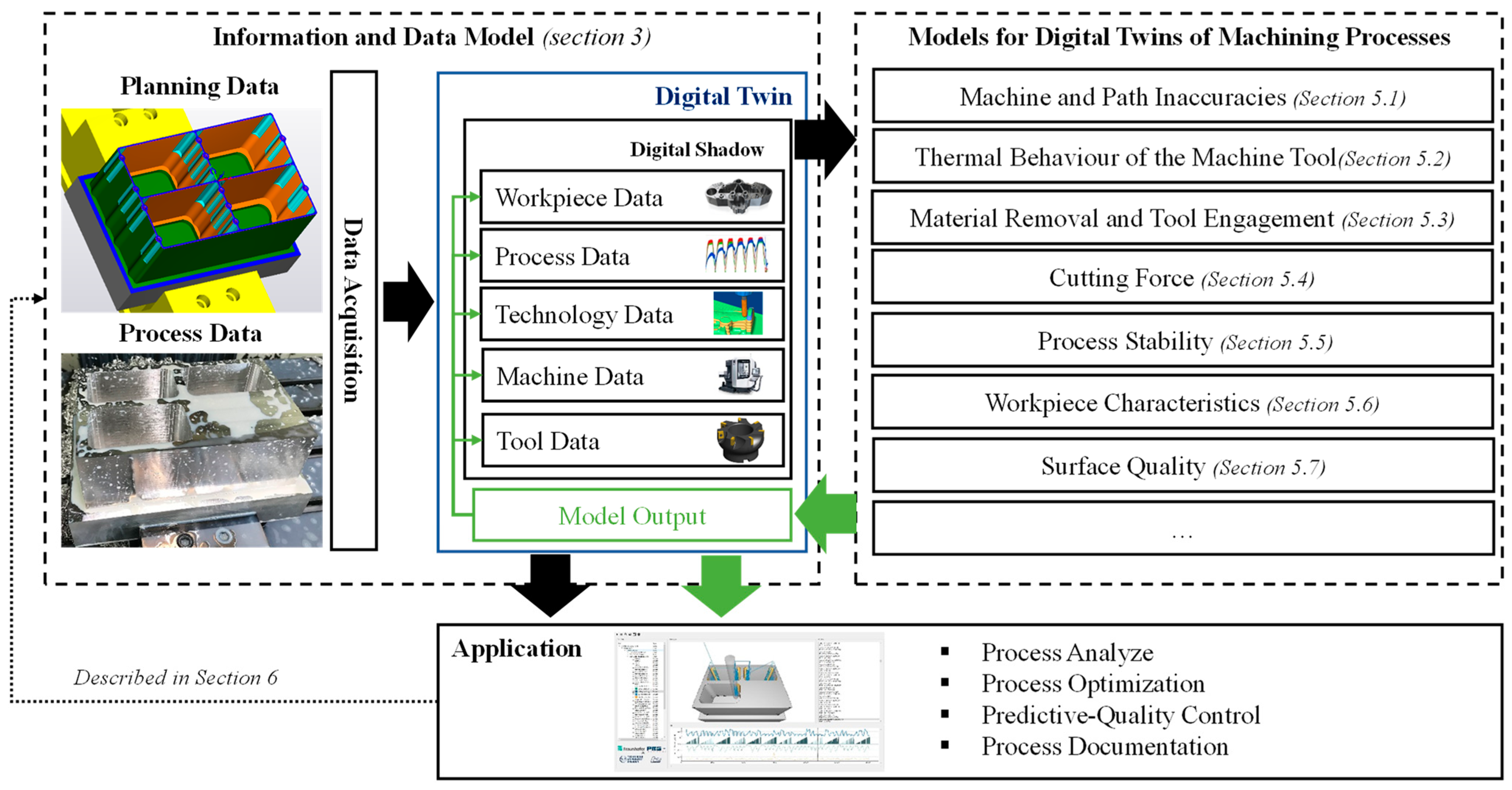
2. Basic Structure of a Digital Twin for Machining Processes

The information model is the heart of standardized and structured data acquisition and covers both the planning data and the process data. (cf. Section 3). Caesar et al. [5] subdivide their information into five data categories (workpiece data, process data, technology data, machine tool data and tool data) which must be made available for the digital representation of the machining process terming the result “digital shadow”. This distinction is made by the authors [5] since the provision of these five data types only creates the prerequisite for a real-time-capable evaluation while the feedback of derived process knowledge is missing or at least not up to date. Either way, the “digital shadow” is seen as an essential part of the physical/virtual transformation in machining (Figure 1). In fact, if implementing different types of models, such as analytical models, empirical models, data-driven models being deepened here in chapter 4, a complex machining process can be represented by a “digital twin” based on the digital shadow input. For digital twins of machining processes, it is particularly important that the “digital (process) twin” not only represents the physical object—respectively the subtractive removed parts of this object (cf. Section 5.3)—but also the machine tool, the machining process as well as the tools and their involvement and interaction in the form of process parameters [5].
Hence, reaching an actual digital twin of the subtractively removed area is a major challenge and requires specific and realistic calculation and process models what is discussed in particular in chapter 4. Nevertheless, the process integration of any derived information in the form of feedback affects the digital shadow (cf. Section 5.4 or Section 5.6) which means that the digital shadow is not necessarily a rigid, unchangeable record but a dynamic object instead (Figure 1).

3. Information and Data Model

The information model is an abstract representation of real objects as well as their properties and interrelationships. The creation of the information model requires expert knowledge and a holistic understanding of process chains in order to be able to decide which information is necessary and relevant and to oversee structuring and classification of what can be expediently shown in case studies [6]. The process of creating an information model requires a structured approach while firstly defining the scope covering the necessary data and required information of, e.g., a milling process. Obviously, this task is inextricably linked with the process models implemented downstream in terms of input variable provision. Moreover, the scope definition includes an interface analysis of each individual data source (e.g., tool data management system) and a boundary condition assessment (e.g., type of data format, sampling rate, etc.) strongly determining the data acquisition after completion [7].
Either way, the result is a structogram without logical contradictions based on internal necessities as well as interdependencies using, e.g., an ontology. However, for the creation of a digital twin of a machining process the interoperability between the process and planning data and its semantic description is an essential aspect for which, unfortunately, there is currently no standardized procedure available. Schroeder et al. [8] presented an information model that supports the simple exchange of data between heterogeneous systems in the context of cyber-physical systems (CPS). Similar approaches are also presented by Alam et al. [9] and Kao et al. [10]. Current research activities end to refer to individual components of the production environment, e.g., the production machine (Cus et al. [11], Moreno et al. [11], DebRoy et al. [12]) or even the entire factory (Uhlemann et al. [13], Siegert et al. [14]). However, the focus of this research is not on information modeling of digital twins of machining processes. Caesar et al. [5], in turn, provide a detailed description of an information model for a 3-axis milling process meeting the formulated requirements. In the context of feedback integration (cf. Section 2), the information model and data models are closely connected (Figure 1), which leads to the question in which form or schema data and information can be filed and stored while providing the possibility of adding further data in a traceable manner. This means, which type, e.g., a relational database, object database, etc., is most suitable for the specific area of application [7].
Moreover, machining processes are highly dynamic such as the process data (e.g., currents of the axis drives, actual positions, etc.) thus being acquired at a sufficiently high sampling rate (up to input–process–output (IPO) cycle of the numerical control (NC) in order to realize the necessary level of detail which, in turn, affects the storage question too. Consequently, large amounts of data have to be stored which requires appropriate formats and must reflect the structure of the information model. A format that fulfills both requirements is the HDF5 format, developed by the National Aeronautics and Space Administration (NASA) [15]. In addition, it must be possible to read out data performantly and allow porting in order to store and reuse the resulting digital twins.

4. Specific Calculation and Process Models

As mentioned before the process models are of crucial importance for obtaining a digital twin (Figure 1). The acquired planning and process data, on the other hand, represent the input for the (different) process models, which means both arise in mutual consideration in order to represent, e.g., tool-workpiece and/or process-machine interaction. The pure consideration of physical effects in the context of specific models (Figure 2), on the other hand, does not inevitably correlate with the machining result because singular effects are frequently super positioning. This means all data and information must be linked until it describes the component with sufficient agreement finally achieving the status of the digital twin, reflecting the entire process chain. Obviously, it is desirable to achieve this in real-time in order to enable, e.g., feedback with little timely offset. Nevertheless, currently, it is not possible to adaptively control a machining process in real-time based on a digital twin. On the other hand, calculation and visualization in a magnitude of 1 s are achievable but require great computing effort [16]. The reduction of this latency towards the IPO cycle of the NC is the subject of current research [17] and will certainly decrease.
The models implemented here, however, aim to describe physical effects in a cause–effect relationship such as the calculation of the cutting force (cf. Section 5.4) with a time offset of several minutes (depending on the precision). In the case of a (physical) machining process more preference is given to analytical-physical models, for example, detailed cutting force models are available (cf. Section 5) while providing a maximum degree of agreement with the physical result [18].
Furthermore, there are statistical and data-driven models [19] that mathematically link to a measured value and a location-specific event (e.g., chatter marks) are suitable too. The latter models can be supplied with data from databases while causalities can be made visible via, e.g., random or fixed correlations. In fact, data-driven models are well suited to determine individual features (e.g., surface defects) linking them to a cause (e.g., tool wear) via experience-based knowledge as part of the digital twin. Either way, the result of this methodical approach in terms of accuracy and resolution strongly depends on the quality of the applied data. If integrating several models, as required to achieve a digital twin of machining processes (cf. Section 2), requires functional interfaces [16] in order to depict interactions realistically. Cutting force and regenerative chatter-induced path deviations, for example, are such accumulated errors that can result in a target-actual-deviation if compared to the component specification in terms of planning data.
However, this shall emphasize the great potential of digital twin-based knowledge [20] that will expand existing value chains by an intangible resource which is specified in the following.

5. Models for Digital Twins of Machining Processes

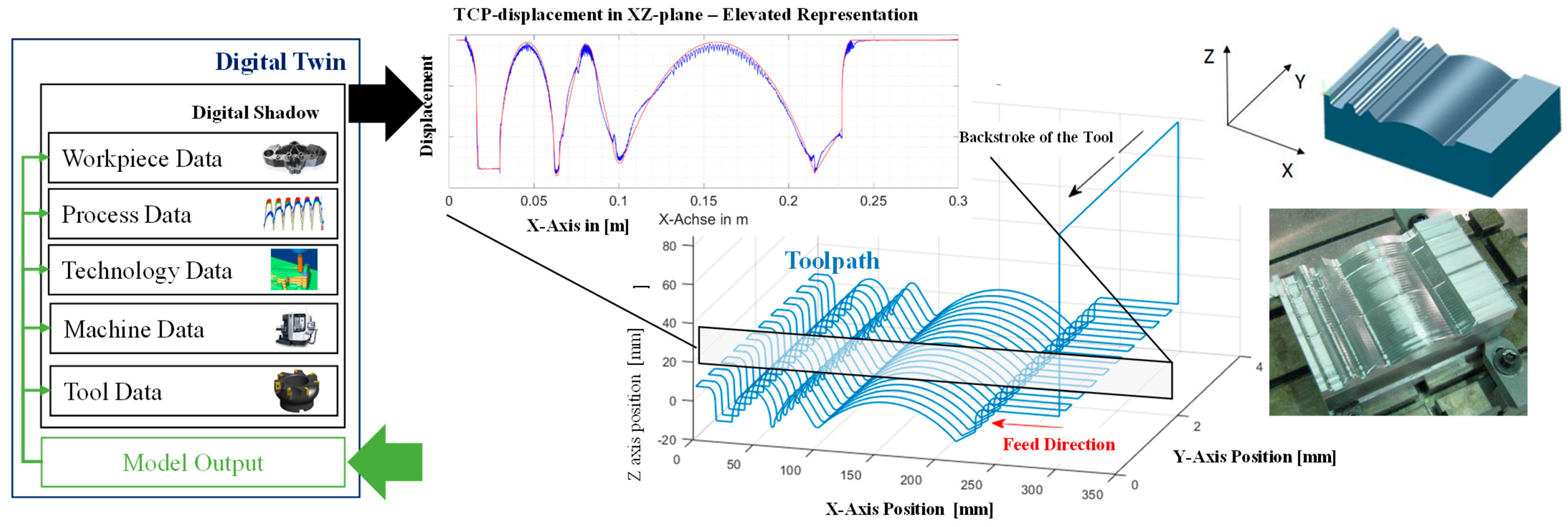
5.1. Machine and Path Inaccuracies

This section deals with machine and path inaccuracies, which are determined in reference to Figure 1, based on the NC information. The acquisition of the current state actual positions via the NC is highly accurate, especially if acquired via a direct position measuring system of the feed axes. Moreover, the actual position can be provided as high-frequency information. Nevertheless, there is a complex mechanical chain with finite stiffness between the feed axes and the tool center point (TCP) which leads to deviations. Depending on the configuration of the machine tool and the implemented process, these deviations can be significant [21]. Consequently, these deviations must be quantified using suitable models thus being an inherent part of the digital twin. In order to evaluate these dynamic path deviations of the particular machine tool, a holistic simulation of the structure and drive control is indispensable [21,22]. Firstly, the dynamic behavior of the mechanics is determined and transferred into a state-space representation [23]. Secondly, the mechanical state-space representation is enhanced by the digital drive control of the machine tool following the well-known cascaded structure approach combined with digital block simulation (DBS).
Following this procedure, an integrated calculation of mechanics and digital drive control can be achieved [23] using the corresponding target values from the NC. In this way, target-actual deviations are causally enriched via the calculation of command variables and derived drive manipulated variables with the mechatronic model, reflecting movement-induced forces and moments. In addition, disturbance variables from the process—for example, spindle load readout and feed axes back transformation—can optionally be applied to the TCP node too. Following this procedure, the actual-target deviation at the direct position measuring systems as well as the actual position of the TCP can be provided taking into account the dynamic machine behavior (Figure 2).
The calculated TCP node can be directly mirrored with the information read out from the NC and thus serve as an independent parameter for evaluating the axis deviations. In addition, this results in an information multiplication (cf. Section 4), which adds to the nominal/actual deviations at the direct position measuring systems of the feed axes, supplements the deviations of the mechanics up to the tool interface for the domains of static and dynamic machine behavior (Figure 2). The result is the actual path movement at the TCP. In this calculation, the other process models (cutting force, etc.) can be integrated in the sense of linking the process models with each other.

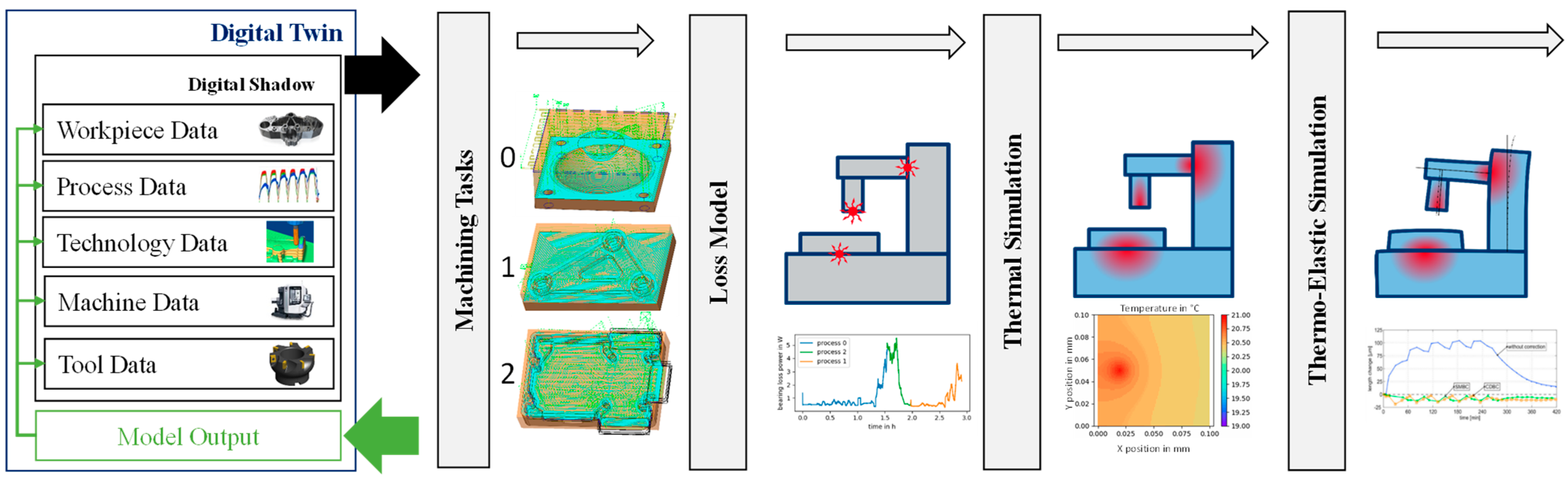
5.2. Thermal Behaviour of the Machine Tool

The thermal stability of machine tools is crucial for the manufacturing of high-quality parts since it is estimated that about 75% of all manufacturing errors can be attributed to thermal effects [24]. The major reason for such thermally induced effects is movement-based losses in machine tool assemblies, which are mainly depending on the operational state of the machine tool. The high frequent axis position information being part of the digital twin allows the time discreet determination of a loss emitting assembly based on the actual operational state. In addition, the process forces (cf. Section 5.4) and the actual mechanical chain representation (cf. Section 5.1) are valuable input variables to obtain the acting forces at the loss-causing assembly. In fact, loss models can be applied (cf. Figure 1) using this information to estimate the heat generation in assemblies such as bearings [25], ball screw drives [26], or motors [27]. This allows estimating temperatures in the machine tool based on task-specific, locally resolved losses based on finite element and structural models. The later models mimic the thermal mechanisms of the real machine tool [28,29] and thus contribute to the integral digital twin.
Nevertheless, the simulation requires the discrete modeling of the entire machine tool, or at least parts of it, to allow heat flow description across thermal interfaces including the parameterization of heat transfers including transient material properties. This means the power losses induced temperature changes are calculated within a fixed interval while considering conduction, convection and radiation of heat. Furthermore, the results of these calculations are included in deformation calculations reflecting the actual temperature fields and their change over time. Consequently, the results of these calculations are used to determine the thermally induced TCP deviation as illustrated in Figure 3 (cf. Figure 2). The proportional TCP deviation, again, influences the component accuracy [29], which makes it a part of the digital twin that can be compared in super positioned form with the physical processing result.
The complete procedure, applicable as a standalone solution or model cascade application (Figure 1), includes loss estimation, thermal simulation and thermo-elastic deformation as illustrated in Figure 3. The integral digital twin provides a suitable framework to forecast thermo-elastic deformations since representative process data are provided by flanking models, which improves the quality of the thermal simulations.

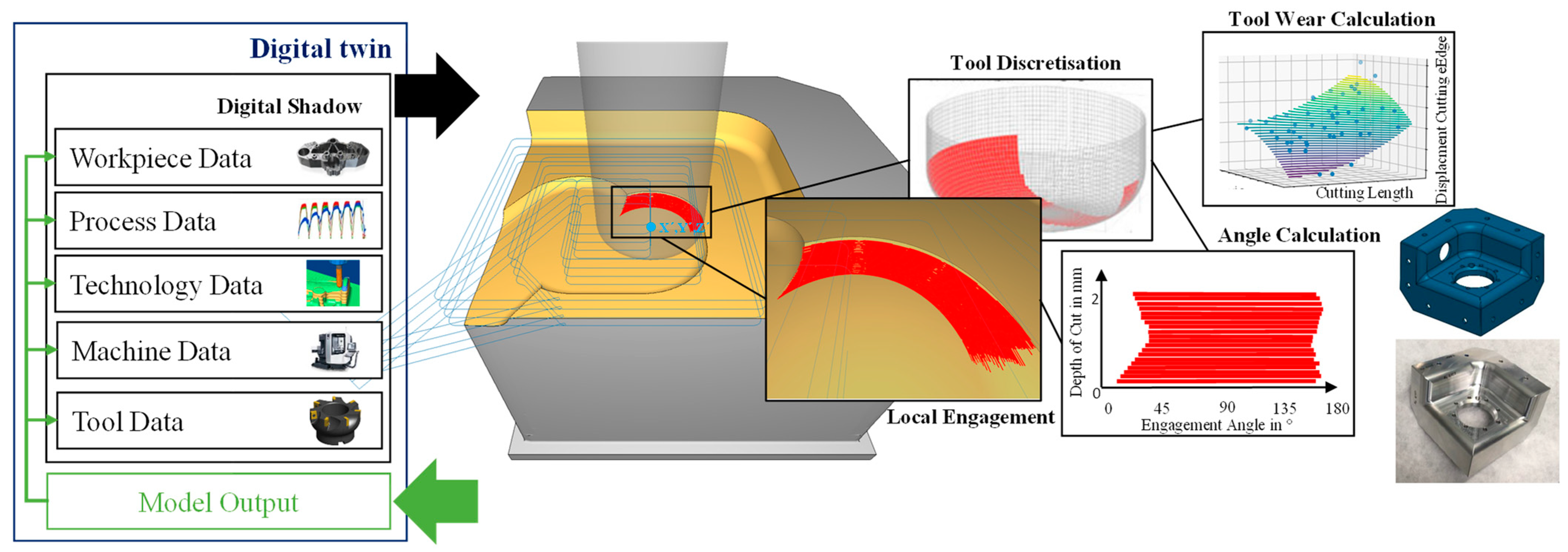
5.3. Material Removal and Tool Engagement
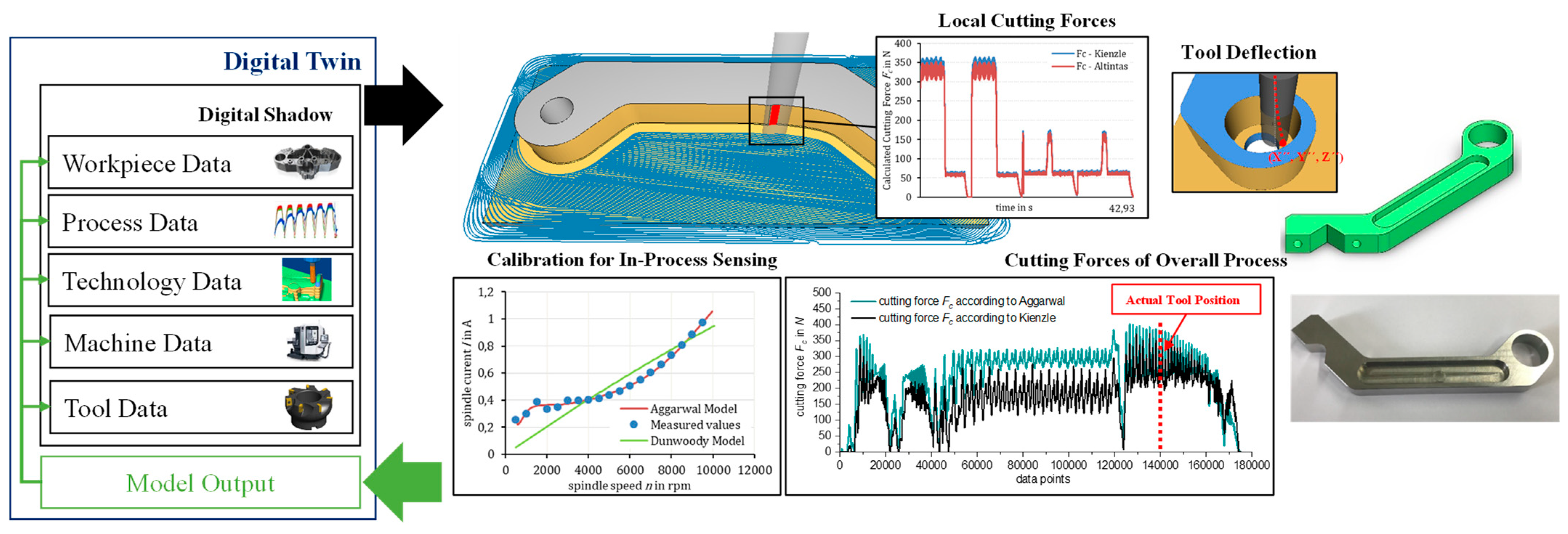
The high-frequency position information read out from the NC and/or the calculated actual position information of the TCP (cf. Section 5.1), are input variables for the time-discrete determination of the geometric tool engagement parameters. Hence, a material removal simulation can be performed, if these data are additionally enhanced by kinematic information as well as tool and workpiece data. As a result, technological information, such as the tool engagement angle, the cutting depth, are calculated based on actual process data. The milling application implies a continuously changing tool-engagement that requires a corresponding coordinate transformation from the actual axes position to the TCP reflecting the machine kinematics provided in the machine data class (cf. Section 2).
There are a number of different methods for calculating tool-workpiece interaction as well as material removal [30]. These methods are either based on spatially partitioned representations, volume-oriented representations or analytical calculation models while being extensively discussed in [30]. Nevertheless, considering accuracy requirements and kinematic complexity from state-of-the-art cutting processes preference is given to simple visualization, e.g., in an as-milled CAD file, which makes multi-dexel models particularly suitable to describe the tool-workpiece-interaction [31] which are a part of the digital twin. Standardized parameters of the tool engagement, e.g., tool engagement angle or cutting depth, are derived from the actual path (cf. Section 5.1) projection. The tool is segmented in order to determine the local engagement while the local engagement, in turn, is resolved segment by segment. Obviously, this approach requires an up-to-date description of the tool including diameter, the number of teeth, cutting edge angle, etc., but also the state of wear. In consequence, relevant tool engagement variables such as cutting angle, average chip thickness, engagement width, etc. can be calculated (Figure 4) for the entire milling process based on documented state change intervals and added to the digital twin [32].
The specific tool information (e.g., diameter, number of teeth, cutting edge angle, etc.) serves as input information for the cutting force calculation or the location-specific process stability determination [33]. The resulting virtual workpiece, based on the output of the material removal simulation, considers the actual position of the TCP (Figure 2), the tool displacement induced by the machining forces (Figure 4) as well as wear (constant between measurements). The result, however, is a spatially discrete mapping of a share of the total path deviation. The total path deviation, in turn, can be approached by the integration of further models (e.g., surface location error) until complete correspondence with the real component, which on the digital side adds up to the complete digital twin.

5.4. Cutting Force

On the basis of the determined geometric engagement parameters of the tool-workpiece interaction, which reflects the position of the actual TCP, the tool displacement and the tool wear, the effective cutting forces can be precisely calculated [34] what is secured by suitable measurement close to the cutting edge [35]. There are different methods for the determination of the cutting forces on the basis of the actual planning and process data [36]. These methods differ in terms of their informative value and suitability as a specific process model that needs to be weighed on a case by case basis [37]. Nevertheless, the method kit includes empirical cutting force models such as the linear model approach from Altintas [38] or the exponential model approach from Kienzle [39]. The size and shape of the chip cross-section (Figure 3) as an explicitly stated influencing variable, on the other hand, is used across all models to determine the uniform empirical representation of the cutting force [40]. All other parameters of the cutting process, such as the angle at the cutting edge, cooling lubricant volume flow, are used implicitly by model-specific constants (e.g., cutting force coefficient, etc.) [41]. These constants must be determined experimentally within the model-specific scope and do not represent a specific workpiece characteristic but rather summarize physical relationships and effects, which makes exact modeling an enormous challenge [36]. In practice, model uncertainties are either accepted or compensated for using statistical methods [42]. The main advantages of these cutting force models are their linkability with the material removal simulation results towards a temporally and spatially resolved cutting force along the toolpath trajectory (Figure 4). For this purpose, Lacalle et al. [43] developed a method and implemented this for the machining of thin and complex components.
Another determination method for the effective cutting forces and feed forces are based on the current commands of the feed or spindle drive motors [44]. A corresponding model captures losses, induced by the structural dynamic chain and/or distortions between the effective point and the motor, in order to calculate the tangential part of the acting cutting force using the torque-forming current obtained in the process [45]. This calculation is performed with a machine-specific calibrated leakage current model [45] to achieve the leakage current for the complete speed range of the spindle. This procedure, which is also described in detail by Hänel et al. [46], is characterized by its simple applicability, low parameterization effort and high accuracy which ensures high practical applicability. In addition, this approach can be transferred to determine radial and axial force components using the feed axes data of the machine tool [4]. Nevertheless, modeling and calibration are significantly more complex for these cutting force components and associated with considerable efforts. Additionally, the calculation of these cutting force components is based on the time and location discrete values of the feed direction angle with respect to the machine reference system, or the current effective components of the feed axes, respectively. As a result, there is a non-linear increase in complexity when performing these calculations for the 5-axis milling process instead of using, e.g., 3-axis. The advantage of this method goes beyond the calculation of effective cutting forces. In fact, the main advantage lies in the ability to integrate these results in the digital shadow while using the in situ process data for the determination of the specific cutting force coefficients (e.g., Altintas, Kienzle) which is described in detail by Arnold et al. [47]. In this way, the input parameter for the below described empirical force calculation is adapted or extended by corresponding process data, which improves the accuracy of the cutting force coefficients. Hence, it should be emphasized that the digital shadow is not a static element—the opposite—the digital shadow continuously evolving, being enriched with calculated process information (cf. Section 2). Furthermore, the linkage of models (e.g., material removal, cutting force, leakage current, etc.) illustrates the systematic approach towards an integral digital twin of the machining process being assest by comparison with the component (Figure 5).

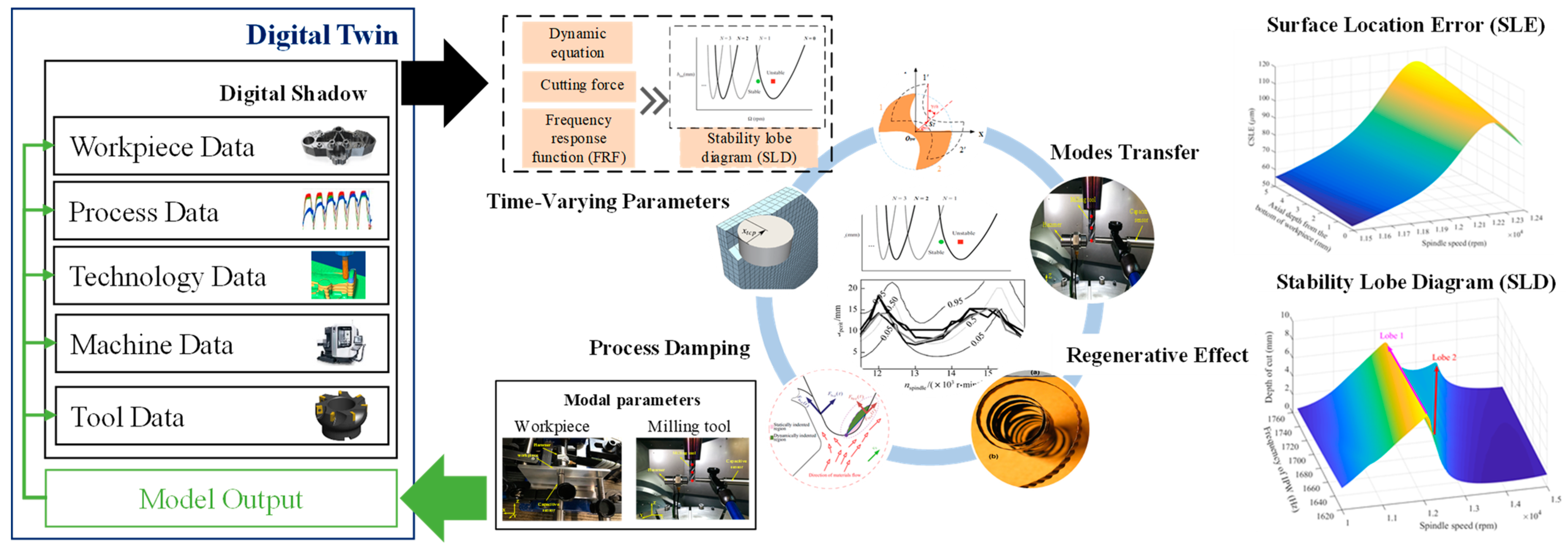
5.5. Process Stability

Chatter is the most important destructive factor in machining, being induced by the self-excited vibration in the machining system [48]. In fact, regenerative chatter is the most common phenomenon during cutting processing, caused by the non-coincidence of the vibrational displacement between the currently engaged and previously engaged tool tooth. The possibility of avoiding chatter mainly depends on the result of the stability lobe diagram (SLD) being achieved by solving the dynamic equations [36]. The construction of the SLD requires the frequency response function of the machining system composed of the tool and workpiece dynamics, i.e., establishing the SLD along the machining tool path. A digital twin of the machine tool enables the user to align virtual and physical machining scenarios, which could bring significant advantages for stability prediction. This shall be emphasized in Figure 6, where the modal parameters of the tool and workpiece are introduced as part of data acquisition while contributing the digital twin for machining processes. Moreover, the modal parameters are updated after every process model integration loop (Figure 5).
Here it shall be emphasized that the frequency variation of the workpiece becomes more significant in the case of continuous material removal [49]. In this case, the SLD prediction algorithm enables the user to integrate the cutting force coefficients, the dynamic parameters at the actual tool position, the modified cut-in and cut-out angles into the chatter prediction model. The vibrational displacement at the actual tool position is recorded and stored in real-time. In connection with the described models below (cf. Section 5.3 and Section 5.4), it will be possible to calculate the dynamic cutting forces which enable the calculation of uncut chip thickness, tool deflection, cut-in and cut-out angles as well as vibration displacement instantaneously while this data is then updated again. Consequently, the stability boundary can be obtained in real-time using previously mentioned data and the chatter metric time-domain criterion [50]. Hence, the cutting process stability can be visualized (Figure 6) such as the TCP–displacement (Figure 2), the tool engagement (Figure 4) and so on which makes a further contribution to the achievement of the digital twin. Nevertheless, it is not trivial to predict if chatter occurs under the given machining situation (cf. Figure 4 and Figure 5) from a simple analysis of two adjacent teeth and consideration of known chatter mechanism. Therefore, all the relevant time instants data (three, four, five or even more time instants) from the start of the NC program are recorded and analyzed. By continuously updating this data, the chatter model not only contributes to the digital twin, in return, but the chatter analysis also benefits from the interlinking with other models (cf. Figure 2) which results in a broader perspective for comprehensive chatter analysis.

5.6. Workpiece Characteristics

As already mentioned in Section 2, the digital process representation is inherently limited to the subtractive removed area. Material data can be discretized in envelop layers. Iterative machining approaches [51], sensory tools [35] and an appropriate selection of the process parameters can increase the number of layers and enrich the data contained. This is understood as a sensitive milling process that helps to detect the material properties of the raw part in order to take measures if necessary. Obviously, this is of greater importance when looking at raw parts made of special materials that have a complex thermo-mechanical manufacturing route. Examples of this are multi-material raw parts [52] or parts with pronounced residual stresses [53]. Either way, the material behavior cannot be predicted trivially in both cases. Consequently, spatially discrete resolved process data enables the identification of graded material properties in reference to the workpiece coordinate system (Figure 7).
Either way, the machining data acquisition ends at the phase boundary. In addition, a plethora of techniques can be used to obtain morphological, chemical, crystallographic or performance data across a range of length scales [54] resulting in a sub-surface data layer that can be linked with the machining data in terms of correlative characterization. In addition, there are non-destructive testing methods such as computed tomography [55] or the investigation by means of neutron radiation [56] which enable the determination of spatially resolved material properties in the sub-surface area. Finally, this concept leads to a digital material twin [57], which also describes the non-machined area integrally. The material digital twin, in turn, can then be integrated as workpiece data (Figure 7).

5.7. Surface Quality

In the previous sections, several models were presented that were introduced to provide digital representations of the machine tool, the tool, the machining strategy of the component including relevant material parameters. Hence a digital twin can be achieved through superposition and interaction of the individual models, which, if it is sufficiently complete, provides a match with the resulting component. In accordance with the approach in the models, process data must be recorded, linked, combined with mathematical correlation and, again, assigned to the corresponding position in order to reflect technological [58], tool- and material-related [59] and machine-related [60] surface quality determining influences [61]. This is a particularly expedient approach since in-process measurements, in turn, only come into use for important molten elements due to the lack of robustness (e.g., due to contamination of the measuring mimic by coolant), process time extension and the additional costs [62]. In fact, the performance of offline measurement is widely limited to the final component state which implies a loss of information about the intermediate states which, is essential in order to learn from the process results while machining [63]. Obviously, the basis for substantial data-based conclusions is a precise match of the macroscopic (surface) parameters, such as first-degree shape deviations, and microscopic parameters in terms of 2nd-degree deviations (waviness) as well as 3rd to 4th-degree deviations in roughness between the component and its digital representation (Figure 8) [64].
Nevertheless, the model-based representation of the as-milled surface is not only an additional benefit in order to, e.g., achieve a first-time-right result for a lot of size one machining tasks by, e.g., gradually approaching the target geometry—in opposite, it is the basis for cost-effective quality control and documentation [65]. Either way, Benardos et al. [59] categorize four types of model-based approaches to illuminate interactions from different perspectives. The first category includes functional relationships between parameters of the machining process and surface parameters classified as models of machining theory (I) [66]. This means that the interaction between tool and material (cf. Section 5.3) is described by an exact description of geometric and kinematic boundary conditions (cf. Figure 2 and Figure 3) [67]. The second category includes the relationship between input parameters from technology, material, tool, machine tool, and process (Figure 2) and a cause’s independent description of the surface (cf. Figure 8) [68] by the means of characteristic values, on the other hand, is classified as an experimental investigation approach (II) [59]. The class of design of experiment (DoE) approach (III) models [69] is a simplified form addressing correlations under controlled study conditions with the focus on reduced effort. The last class groups artificial intelligence approaches (IV) [70,71] which are often difficult to describe from a mathematical perspective.
This fourth class was particularly created to identify reliable correlations between input and output parameters in a data-driven manner even without in-depth knowledge of the underlying physical and kinematic relationships [72]. Lu [73] provides a similar categorization, sub-grouping into pure models (I), comparable with physical models of machining theory (cf. Figure 1), and signal- and artificial intelligence-based approaches (II). The latter takes into account the origin of the datasets been used to describe the surface quality. Examples of such sources are optics and computer vision, ultrasonic, acoustic emission and vibration-based methods whose measured values, must be made available in a spatially resolved manner. This means the indirect determination of surface quality parameters arises partly from the use of the utilization of the digital shadow data described in this paper in order to, e.g., determine shape deviations of the 1st and 2nd degree. The basis for this is the appropriate modeling of the tool shape and tool properties (cf. Figure 3) as well as the knowledge of the actual technological parameter settings (e.g., tooth feed, velocities, etc.) as approached in Figure 4. In fact, tool engagement simulations (cf. Section 5.3) provide high-resolution chip characteristics based on in-depth force models (cf. Section 5.4) which, in turn, are used as input for sophisticated tool displacement models [74], which results in a surface error location (SLE) [75].
Either way, the result is illustrated in Figure 8. Nevertheless, shape deviations of the 3rd to 4th degree, on the other hand, cannot be determined with comparable accuracy. The reasons for this [76] are seen in a rather unsuitable signal-to-noise ratio of the machine sensors, a lack of knowledge regarding the locally discrete material properties (cf. Section 5.6) as well as the discontinuous monitoring of tool wear as already discussed in Section 5.3. Nevertheless, there are also approaches pointing in this direction such as the surface roughness models introduced by Bauer et al. [77] or Teicher et al. [78] as well as the additional surface roughness models from Brammertz [79] or Brown [80]. Either way, the lower resolution range for 3rd-degree shape deviations is currently seen in the magnitude of more than 30 µm, if the calculation is based on the digital shadow data. A better resolution, on the other hand, is only achievable under optimal conditions (e.g., turning of easily machinable materials with a stiff machine using stiff, non-worn tools). Regardless of this, the downstream measurements are also a part of the digital twin.

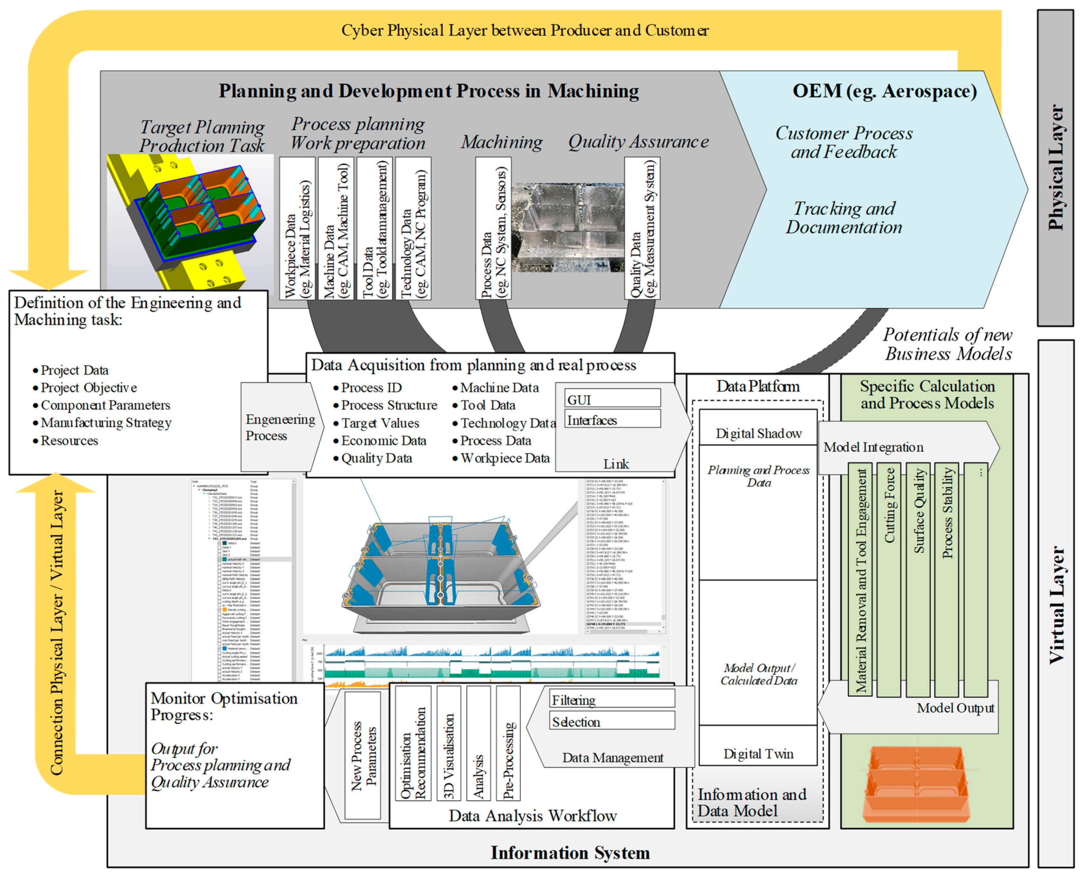
6. Concept of an Application-Oriented Implementation of Model-Based Digital Twins

6.1. Introduction to the Software System Architecture

In the first part of the Paper, the model-based digital representation of a machining process was explained, which was further superimposed towards a digital twin for machining processes that correspond to the manufactured component. The next part of the paper, in turn, clarifies how the presented procedure can be implemented in an application-oriented manner, e.g., on a shop floor level (Figure 9).
Sztipanovits et al. [81] state in this regard that the heterogeneity of tasks, data and information is an enormous challenge for a successful implementation. Jedrzejewski et al. [82] confirm this conclusion and also present a linkage approach for machining technology applications with a strong focus on a digital representation of the machine and its control. This work, on the other hand, goes beyond that by taking into account the tool (Figure 2) as well as the component (Figure 3, Figure 4 and Figure 5) and the material (Figure 7). Hence, the physical layer of a classic forward-oriented planning process is extensively expanded by a virtual layer, that reflects the models presented at the beginning, in order to firstly illustrate these relationships (Figure 9).
Moreover, the essential links between the virtual and physical layer are set out based on the underlying information model presented at the beginning (cf. Section 2) which is explained in the following chapters. The results are an integral description of a software architecture for an information system, which can be integrated into a manufacturing company while providing a digital twin for the machining process based on connected process models (cf. Section 4). In addition, a return of the cyber-physically enabled digital twin is illustrated. This way, the digital process is transformed into an immaterial resource, which can serve as an information basis for future machining tasks as a digitally preserved experience.

6.2. Target Definition and Data Collection

The classic forward-oriented planning process starts with the definition of the manufacturing tasks based on measurable target parameters usually specified by the client (Figure 9, definition of the engineering and machining task). Examples of that are the base material selection, target geometry and surface quality as well as flanking business information. Either way, the target parameters defined in this task have a strong impact on the downstream data acquisition measures and thus on the value of the component as well as the digital twin for machining processes. This means those responsible for planning have to be aware of the mathematical relationships in modeling (cf. Section 5) to prepare for optimization strategies from the very beginning. In fact, there is a decisive share in the development of a digital twin resource, attributed to the early definition stage (Figure 8), which further ensures that the value of the resulting immaterial resource goes beyond the pure documentation. At this stage, in addition, existing connectors such as enterprise-resource-planning (ERP) system [83], computer-aided manufacturing (CAM) system [82] and manufacturing execution system (MES) [84] must be taken into account, because of their importance for the downstream data acquisition. The planning task, divided into four main groups (material, machine, tool and the technology data) in the first part of the paper (cf. Section 2), must guarantee the later availability of the corresponding data (cf. Figure 2, Figure 3, Figure 4, Figure 5, Figure 6, Figure 7 and Figure 8). For example, a geometric description of the tools is required (e.g., CAD models) which should preferably be made available in accordance with the ISO13399 standard [85]. Furthermore, a digital representation of the machine tool or at least the kinematic chain is required, in order to create the associated model (cf. Section 5.1). Looking at the technology data, all planning information, such as clamping situation, nominal geometry, NC program, etc., must be linked to information systems Figure 8). In addition, there are the actual process data (cf. Section 2), e.g., actual/nominal positions, drive currents of the spindles and axes, PLC signals, etc., going to be acquired directly or indirectly during actual machining. Hence, a data interface to the NC of the machine tool must be available, in order to allow process data acquisition within time scales of the IPO cycle (high-frequency data), as explained in detail by Hänel et al. [51]. This requires specific solutions since this is very control-specific. Trabesinger et al. [86], provides an interface description for an Sinumerik Edge which, unfurtunatly, cannot be transferred to other numerical control systems (e.g., Fanuc, Heidenhain etc.).

6.3. Data Platform and Data Model

The data platform accommodates all planning and process data, filed after write once read many (WORM) precautions to ensure the authenticity of the data [51] as well as the model output and the individual output of the models as well as the linked-model data. The underlying storage logic is determined by the information model while HDF5 was chosen as the format for the implementation (c.f. Section 3). The data platform consists of time-stratified data layers that archive the shadow-twin transformation loop (c.f. Section 2 and Figure 9). Compatible object storage is used to store and retrieve data directly from the machine, providing industry-leading durability, availability, performance, security, and virtually unlimited scalability at production location: The cloud storage uses objects rather than blocks or files while enabling to store data, along with metadata that identifies and describes the content [51]. Standardized platform-independent communication protocols, such as OPC UA, MT Connect [87] are used as communication interfaces for the data transfer to the data platform.

6.4. Model Integration

Models (c.f. Section 5) are either data-driven, combining measured values and physical properties, or physical, describing clear cause-effect relationships [88]. The models receive the process data via the data platform as digital shadows and make proportional contributions to the final digital twin for machining processes (Figure 9 and Section 2). The digital twin, achieved by cascading model outputs (Figure 9, calculation in specific process models), reaches its final status after the real and the virtual component match each other, while both meet the measurable target parameters (c.f. Section 6.2).

6.5. Visualisation, Analysis and Feedback

A central motivation for the presented digital twin for machining processes is a simple representation of the machining results, which are the consequence of complex causal relationships. The form of representation (c.f. Figure 2, Figure 3, Figure 4, Figure 5, Figure 6, Figure 7 and Figure 8) is easier to understand and faster to interpret than the underlying mathematics. This shall facilitate the exchange between interdisciplinary scientific fields, which is seen as a decisive advantage when dealing with complex machining tasks. For example, can tailor-made heat treatments be derived based on a quantified shape deviation (Figure 8) and, e.g., an identified property grading (Figure 7) if this is detected before the target geometry is reached (c.f. Section 6.2). Obviously, this is not a decisive aspect of producing large component quantities from standard materials. On the contrary, there is more the aspect of quality assurance in the foreground, where suitable visualization methods can obviously bring advantages too. Nevertheless, if looking at high-performance material-based high-tech components there is a priority extension. In addition to the aspect of quality assurance, information exploration is added as an extended motivator. This means, to enable to combine early knowledge gain (c.f. Section 5) with appropriate measures in order to enable the achievement of the target specifications (c.f. Section 6.2). Either way, spatially discrete linkage of process data and/or the model output (Figure 9) is the decisive requirement for visualization using graphs, plots or histograms (Figure 2, Figure 3, Figure 4, Figure 5, Figure 6, Figure 7 and Figure 8). Specifically, this means, for example, to perform the material removal simulation (c.f. Section 5.3) with the actual axes data instead of an NC interpreter. Nevertheless, the reference to the current NC line is particularly important, as these are the basis for feedback measures, in terms of, e.g., feed rate adjustments. The cascaded models (Figure 9), on the other hand, are essential for situation-adapted feedback. In fact, the models are superimposed to form the digital twin, while the basis for the derivation of measures, in turn, is created by their individual contributions. For example, the influence of tool deflection on component accuracy can be identified in isolation.

7. Summary

A basic digital twin structure was presented based on an existing information model. The digital twin results from cascading of specific process model output determining machine and path inaccuracies, material removal and tool engagement, cutting force, process stability, thermal behavior, workpiece and surface properties. The digital shadow created by task definition as well as data acquisition from planning and processing provides the input data for these models. The model output is superimposed to a digital twin that corresponds to the real component that unites the real and virtual world. The model output, individually or superposed, is visualized in an easily comprehensible manner. This process-related consideration is further extended in favor of an integral software architecture approach, based on forward-oriented planning from operational practice. As a result, the introduced information model and the process models are expanded to include task definition and data collection, data platform and data handling as well as model integration. Finally, visualization, analysis and feedback are discussed and an outlook is given.

8. Outlook

The paper presented a general model structure for digital twins with exemplary functionalities in the context of machining processes. Such digital twins in their final form could achieve a major benefit for manufacturers. It supports the structured acquisition of manufacturing relevant data, which can be used for quality assurance and documentation. Furthermore, the structured database (digital shadow) allows the application of various process-relevant models, which helps to understand the fundamental mechanisms of the machining processes. This provides the knowledge base to make optimizations to the cutting process itself to increase machining quality as well as resource efficiency.
Increasing model accuracy will be an important topic for further research, since the achievable process errors, such as positioning errors, are caused by several nonlinear physical effects during the machining process and are not all known in advance. Therefore, the individual models need to be monitored by back calculating the model accuracy using the various available data sources. AI-solutions, e.g., root-cause analysis, probabilistic approaches such as Bayesian networks, are the key to scan all sub-instances of the digital twin and continuously adjust the model parameters based on the current database.
Another relevant point for the research will be the model connection and calculation since there can be a bidirectional relationship between the models, which requires an iterative approximation approach. For example, the tool engagement causes a force to deflect the tool, which in turn causes the tool engagement to change, changing the starting point of consideration. The reverse calculation of the interactions of the individual model instances, e.g., changes in tool engagement due to machine deviations, must be integrated individually and modularly via a secondary model layer. The results of this layer can later be transferred to a process chain level. Automatic detection of such loops could greatly simplify model integration, as calculation strategies could be automatically determined depending on the model dependencies.

Author Contributions

Conceptualization, A.H. (Albrecht Hänel), E.W.; L.P. and A.H. (Arvid Hellmich); formal analysis, U.F.; investigation, U.T. and H.W.; resources, A.H. (Arvid Hellmich); data curation, D.W.; writing—original draft preparation, A.H. (Albrecht Hänel) and A.S.; writing—review and editing, U.T., A.S. and L.P.; visualization, U.T. and D.W.; supervision, A.H. (Arvid Hellmich), A.S.; project administration, S.I.; funding acquisition, A.H. (Albrecht Hänel) and S.I. All authors have read and agreed to the published version of the manuscript.

Funding

The German Aerospace Center (DLR) funded this research with the grant number 20Q1965C.

Data Availability Statement

The data presented in this study are available on request from the corresponding author.

Acknowledgments

The authors would like to thank the Federal Ministry of Economics and Technology (BMWi) and the German Aerospace Center (DLR) for funding this paper as part of the research project “TwinProCut” of the aeronautics research program (LuFo VI-1).

Conflicts of Interest

The authors declare no conflict of interest.

References

  1. Uhlemann, T.H.-J.; Schock, C.; Lehmann, C.; Freiberger, S.; Steinhilper, R. The Digital Twin: Demonstrating the Potential of Real Time Data Acquisition in Production Systems. Procedia Manuf. 2017, 9, 113–120. [Google Scholar] [CrossRef]
  2. Armendia, M.; Ghassempouri, M.; Ozturk, E.; Peysson, F. (Eds.) Twin-Control; Springer International Publishing: Cham, Switzerland, 2019. [Google Scholar]
  3. Rosen, R.; Von Wichert, G.; Lo, G.; Bettenhausen, K. About the Importance of Autonomy and Digital Twins for the Future of Manufacturing; IFAC-PapersOnLine; Elsevier Ltd.: Amsterdam, The Netherlands, 2015; Volume 28, pp. 567–572. [Google Scholar]
  4. Altintas, Y.; Aslan, D. Integration of virtual and on-line machining process control and monitoring. CIRP Ann. 2017, 66, 349–352. [Google Scholar] [CrossRef]
  5. Caesar, B.; Hanel, A.; Wenkler, E.; Corinth, C.; Ihlenfeldt, S.; Fay, A. Information Model of a Digital Process Twin for Machining Processes. In Proceedings of the 2020 25th IEEE International Conference on Emerging Technologies and Factory Automation, Vienna, Austria, 8–11 September 2020; IEEE: New York, NY, USA, 2020; pp. 1765–1772. [Google Scholar]
  6. West, M. Some Types and Uses of Data Models. In Developing High Quality Data Models; Elsevier: Amsterdam, The Netherlands, 2011; pp. 23–36. [Google Scholar]
  7. Lee, Y.T. Information modeling: From design to implementation. In Proceedings of the Second World Manufacturing Congress, Manchester, UK, 9–11 April 2019; Academic Press: Cambridge, MA, USA, 2004; pp. 1–7. [Google Scholar]
  8. Schroeder, G.N.; Steinmetz, C.; Pereira, C.E.; Espindola, D.B. Digital Twin Data Modeling with AutomationML and a Communication Methodology for Data Exchange; IFAC-PapersOnLine: Amsterdam, The Netherlands, 2016; Volume 49, pp. 12–17. [Google Scholar]
  9. Alam, K.M.; El Saddik, A. C2PS: A digital twin architecture reference model for the cloud-based cyber-physical systems. IEEE Access 2017, 5, 2050–2062. [Google Scholar] [CrossRef]
  10. Kao, H.; Jin, W.; Siegel, D.; Lee, J. A Cyber Physical Interface for Automation Systems—Methodology and Examples. Machines 2015, 3, 93–106. [Google Scholar] [CrossRef]
  11. Moreno, A.; Velez, G.; Ardanza, A.; Barandiaran, I.; Infante, A.R.; Chopitea, R. Virtualisation process of a sheet metal punching machine within the Industry 4.0 vision. Int. J. Interact. Des. Manuf. 2017, 11, 365–373. [Google Scholar] [CrossRef]
  12. DebRoy, T.; Zhang, W.; Turner, J.; Babu, S.S. Building digital twins of 3D printing machines. Scr. Mater. 2017, 135, 119–124. [Google Scholar] [CrossRef]
  13. Uhlemann, T.H.J.; Lehmann, C.; Steinhilper, R. The Digital Twin: Realizing the Cyber-Physical Production System for Industry 4.0. Procedia CIRP 2017, 61, 335–340. [Google Scholar] [CrossRef]
  14. Siegert, J.; Schlegel, T.; Groß, E.; Bauernhansl, T. Standardized Coordinate System for Factory and Production Planning. Procedia Manuf. 2017, 9, 127–134. [Google Scholar] [CrossRef]
  15. Folk, M.; Heber, G.; Koziol, Q.; Pourmal, E.; Robinson, D. An overview of the HDF5 technology suite and its applications. In Proceedings of the EDBT/ICDT 2011 Workshop on Array Databases—AD ’11, Uppsala, Sweden, 25 March 2011; ACM Press: New York, NY, USA, 2011; pp. 36–47. [Google Scholar]
  16. Zhang, J.; Deng, C.; Zheng, P.; Xun, X.; Zhentao, M. Development of an edge computing-based cyber-physical machine tool. Robot Comput. Integr. Manuf. 2021, 67, 102042. [Google Scholar] [CrossRef]
  17. Zhao, L.; Fang, Y.; Lou, P.; Junwei, Y.; Xiao, A. Cutting Parameter Optimization for Reducing Carbon Emissions Using Digital Twin. Int. J. Precis. Eng. Manuf. 2021, 22, 933–949. [Google Scholar] [CrossRef]
  18. Wei, Z.C.; Guo, M.L.; Wang, M.J.; Li, S.Q.; Liu, S.X. Prediction of cutting force in five-axis flat-end milling. Int. J. Adv. Manuf. Technol. 2018, 96, 137–152. [Google Scholar] [CrossRef]
  19. Liang, Y.C.; Wang, S.; Li, W.D.; Lu, X. Data-Driven Anomaly Diagnosis for Machining Processes. Engineering 2019, 5, 646–652. [Google Scholar] [CrossRef]
  20. Tao, F.; Cheng, J.; Qi, Q.; Zhang, M.; Zhang, H.; Sui, F. Digital twin-driven product design, manufacturing and service with big data. Int. J. Adv. Manuf. Technol. 2018, 94, 3563–3576. [Google Scholar] [CrossRef]
  21. Neugebauer, R.; Ihlenfeldt, S.; Frieß, U.; Wabner, M.; Rauh, S. New high-speed machine tool structure by holistic mechatronic systems design. Procedia CIRP 2012, 1, 307–312. [Google Scholar] [CrossRef]
  22. Altintas, Y.; Verl, A.; Brecher, C.; Uriarte, L.; Pritschow, G. Machine tool feed drives. CIRP Ann. 2011, 60, 779–796. [Google Scholar] [CrossRef]
  23. Neugebauer, R.; Scheffler, C.; Wabner, M.; Zwingenberger, C. Advanced calculation of static and dynamic stiffness in mechatronic machine tools. Int. J. Mechatron. Manuf. Syst. 2011, 4, 370. [Google Scholar] [CrossRef]
  24. Mayr, J.; Jedrzejewski, J.; Uhlmann, E.; Donmez, M.A.; Knapp, W.; Härtig, F.; Wendt, K.; Moriwaki, T.; Shore, P.; Schmitt, R. Thermal issues in machine tools. CIRP Ann. 2012, 61, 771–791. [Google Scholar] [CrossRef] [Green Version]
  25. Kauschinger, B.; Schroeder, S. Uncertainties in Heat Loss Models of Rolling Bearings of Machine Tools. Procedia CIRP 2016, 46, 107–110. [Google Scholar] [CrossRef] [Green Version]
  26. Rigacci, M.; Sato, R.; Shirase, K. Experimental evaluation of mechanical and electrical power consumption of feed drive systems driven by a ball-screw. Precis. Eng. 2020, 64, 280–287. [Google Scholar] [CrossRef]
  27. Winkler, S.; Werner, R. Thermo-Energetic Motor Optimisation; Springer: Berlin/Heidelberg, Germany, 2015; pp. 223–231. [Google Scholar]
  28. Galant, A.; Beitelschmidt, M.; Großmann, K. Fast High-Resolution FE-based Simulation of Thermo-Elastic Behaviour of Machine Tool Structures. Procedia CIRP 2016, 46, 627–630. [Google Scholar] [CrossRef] [Green Version]
  29. Thiem, X.; Kauschinger, B.; Ihlenfeldt, S. Structure Model Based Correction of Thermally Induced Motion Errors of Machine Tools. Procedia Manuf. 2017, 14, 128–135. [Google Scholar] [CrossRef]
  30. Altintas, Y.; Kersting, P.; Biermann, D.; Budak, E.; Denkena, B.; Lazoglu, I. Virtual process systems for part machining operations. CIRP Ann. Manuf. Technol. 2014, 63, 585–605. [Google Scholar] [CrossRef]
  31. Friedrich, J.; Gebele, M.A.; Lechler, A.; Verl, A. Determining the Width and Depths of Cut in Milling on the Basis of a Multi-Dexel Model. In Proceedings of the ICAMET 2015 International Conference on Advanced Manufacturing Engineering and Technologies, Istanbul, Turkey, 26–27 October 2015; Volume 2, p. 662. [Google Scholar]
  32. Hänel, A.; Schnellhardt, T.; Wenkler, E.; Nestler, A.; Brosius, A.; Corinth, C.; Fay, A.; Ihlenfeldt, A. The development of a digital twin for machining processes for the application in aerospace industry. Procedia CIRP 2020, 93, 1399–1404. [Google Scholar] [CrossRef]
  33. Lamikiz, A.; De Lacalle, L.N.L.; Sánchez, J.A.; Salgado, M.A. Cutting force estimation in sculptured surface milling. Int. J. Mach. Tools Manuf. 2004, 44, 1511–1526. [Google Scholar] [CrossRef]
  34. Matsubara, A.; Ibaraki, S. Monitoring and Control of Cutting Forces in Machining Processes: A Review. Int. J. Autom. Technol. 2009, 3, 445–456. [Google Scholar] [CrossRef]
  35. Drossel, W.-G.; Gebhardt, S.; Bucht, A.; Kranz, A.; Schneider, J.; Ettichrätz, M. Performance of a new piezoceramic thick film sensor for measurement and control of cutting forces during milling. CIRP Ann. 2018, 67, 45–48. [Google Scholar] [CrossRef]
  36. Altintas, Y. Manufacturing Automation: Metal Cutting Mechanics, Machine Tool Vibrations, and CNC Design; Cambridge University Press: Cambridge, UK, 2012. [Google Scholar]
  37. Olvera, D.; Artetxe, E.; Luo, M.; Urbikain, G. 5-axis milling of complex parts with barrel-shape cutter: Cutting force model and experimental validation. Procedia Manuf. 2020, 48, 528–532. [Google Scholar] [CrossRef]
  38. Altintaş, Y.; Lee, P. A General Mechanics and Dynamics Model for Helical End Mills. CIRP Ann. 1996, 45, 59–64. [Google Scholar] [CrossRef]
  39. Kienzle, V. Spezifische Schnittkräfte bei der Metallbearbeitung. Werkstatttechnik Und Masch. 1957, 47, 224–225. [Google Scholar]
  40. Boz, Y.; Erdim, H.; Lazoglu, I. Modeling cutting forces for five axis milling of sculptured surfaces. Adv. Mater. Res. 2011, 223, 701–712. [Google Scholar] [CrossRef] [Green Version]
  41. Artetxe, E.; Urbikain, G.; Lamikiz, A.; de-Lacalle, L.N.L.; González, R.; Rodal, P. A Mechanistic Cutting Force Model for New Barrel End Mills. Procedia Eng. 2015, 132, 553–560. [Google Scholar] [CrossRef] [Green Version]
  42. Hanief, M.; Wani, M.F.; Charoo, M.S. Modeling and prediction of cutting forces during the turning of red brass (C23000) using ANN and regression analysis. Eng. Sci. Technol. Int. J. 2017, 20, 1220–1226. [Google Scholar] [CrossRef] [Green Version]
  43. de Lacalle, L.N.L.; Lamikiz, A.; Sánchez, J.A.; de Bustos, I.F. Simultaneous measurement of forces and machine tool position for diagnostic of machining tests. IEEE Trans. Instrum. Meas. 2005, 54, 2329–2335. [Google Scholar]
  44. Klocke, F.; Kratz, S.; Veselovac, D. Position-oriented process monitoring in freeform milling. CIRP J. Manuf. Sci. Technol. 2008, 1, 103–107. [Google Scholar] [CrossRef]
  45. Aggarwal, S.; Nešić, N.; Xirouchakis, P. Cutting torque and tangential cutting force coefficient identification from spindle motor current. Int. J. Adv. Manuf. Technol. 2013, 65, 81–95. [Google Scholar] [CrossRef]
  46. Hanel, A.; Wenkler, E.; Schnellhardt, T.; Corinth, C.; Brosius, A.; Fay, A.; Nestler, A. Development of a method to determine cutting forces based on planning and process data as a contribution for the creation of digital process twins. MM Sci. J. 2019, 2019, 3148–3155. [Google Scholar] [CrossRef]
  47. Arnold, F.; Hänel, A.; Nestler, A.; Brosius, A. New Approaches for the Determination of Specific Values for Process Models in Machining Using Artificial Neural Networks. Procedia Manuf. 2017, 11, 1463–1470. [Google Scholar] [CrossRef]
  48. Quintana, G.; Ciurana, J. Chatter in machining processes: A review. Int. J. Mach. Tools Manuf. 2011, 51, 363–376. [Google Scholar] [CrossRef]
  49. Wang, D.; Löser, M.; Luo, Y.; Ihlenfeldt, S.; Wang, X.; Liu, Z. Prediction of cumulative surface location error at the contact zone of in-process workpiece and milling tool. Int. J. Mech. Sci. 2020, 177, 105543. [Google Scholar] [CrossRef]
  50. Honeycutt, A.; Schmitz, T.L. A New Metric for Automated Stability Identification in Time Domain Milling Simulation. J. Manuf. Sci. Eng. 2016, 138. [Google Scholar] [CrossRef]
  51. Hänel, A.; Seidel, A.; Willy, C.; Dementyev, A.; Kozak, K.; Seidel, R.; Teicher, U.; Hellmich, A.; Drossel, W.G.; Ihlenfeldt, S. Impact of Cyber-physically enhanced manufacturing on the product requirement documentation in high-tech applications. 2021, in press. [Google Scholar]
  52. Brueckner, F.; Riede, M.; Müller, M.; Marquardt, F.; Willner, R.; Seidel, A.; Lopéz, E.; Leyens, C.; Beyer, E. Enhanced manufacturing possibilities using multi-materials in laser metal deposition. J. Laser Appl. 2018, 30, 032308. [Google Scholar] [CrossRef]
  53. Seidel, A. Integral Approach for Hybrid Manufacturing of Large Structual Titanium Space Components. Ph.D. Thesis, TU Dresden University, Dresden, Germany, 2021. [Google Scholar]
  54. Burnett, T.L.; Withers, P.J. Completing the picture through correlative characterization. Nat. Mater. 2019, 18, 1041–1049. [Google Scholar] [CrossRef]
  55. Lopez, E.; Felgueiras, T.; Grunert, C.; Brückner, F.; Riede, M.; Seidel, A.; Marquardt, A.; Leyens, C.; Beyer, E. Evaluation of 3D-printed parts by means of high-performance computer tomography. J. Laser Appl. 2018, 30, 032307. [Google Scholar] [CrossRef]
  56. Ramadhan, R.S.; Cabeza, S.; Pirling, T.; Kabra, S.; Hofmann, M.; Rebelo Kornmeier, J.; Venter, A.M.; Marias, D. Quantitative analysis and benchmarking of positional accuracies of neutron strain scanners. Nucl. Instrum. Methods Phys. Res. Sect. A Accel. Spectrometers Detect. Assoc. Equip. 2021, 999, 165230. [Google Scholar] [CrossRef]
  57. Schweizer, C. Final Report «MaterialDigital». 2020. Available online: http://publica.fraunhofer.de/documents/N-608495.html (accessed on 27 July 2021).
  58. Torims, T.; Logins, A.; Rosado, P.C.; Gutiérrez, S.; Torres, R. The Dependence of 3D Surface Roughness Parameters on High-Speed Milling Technological Parameters and Machining Strategy. Adv. Manuf. Am. Soc. Mech. Eng. 2014. [Google Scholar] [CrossRef]
  59. Benardos, P.G.; Vosniakos, G.-C. Predicting surface roughness in machining: A review. Int. J. Mach. Tools Manuf. 2003, 43, 833–844. [Google Scholar] [CrossRef]
  60. Klocke, F.; Kuchle, A. Metrology and Workpiece Quality; Springer: Berlin/Heidelberg, Germany, 2011; pp. 3–37. [Google Scholar]
  61. Urbikain, G.; de Lacalle, L.N.L. Modelling of surface roughness in inclined milling operations with circle-segment end mills. Simul. Model. Pract. Theory 2018, 84, 161–176. [Google Scholar] [CrossRef]
  62. Gao, W.; Haitjema, H.; Fang, F.Z.; Leach, R.K.; Cheung, C.F.; Savio, E.; Linares, J.M. On-machine and in-process surface metrology for precision manufacturing. CIRP Ann. 2019, 68, 843–866. [Google Scholar] [CrossRef] [Green Version]
  63. Seidel, A.; Gollee, C.; Schnellhardt, T.; Hammer, M.; Dassing, J.; Vogt, R.; Wiese, T.; Teicher, U.; Hellmich, A.; Ihlenfeldt, S.; et al. Cyber-physical approach toward semiautonomous postprocessing of additive manufactured parts and components. J. Laser Appl. 2021, 33, 012033. [Google Scholar] [CrossRef]
  64. Davim, J.P. (Ed.) Surface Integrity in Machining; Springer: London, UK, 2010. [Google Scholar]
  65. Zeroudi, N.; Fontaine, M.; Necib, K. Prediction of cutting forces in 3-axes milling of sculptured surfaces directly from CAM tool path. J. Intell. Manuf. 2012, 23, 1573–1587. [Google Scholar] [CrossRef]
  66. Saini, S.; Ahuja, I.S.; Sharma, V.S. Influence of cutting parameters on tool wear and surface roughness in hard turning of AISI H11 tool steel using ceramic tools. Int. J. Precis. Eng. Manuf. 2012, 13, 1295–1302. [Google Scholar] [CrossRef]
  67. Artetxe, E.; Olvera, D.; de Lacalle, L.N.L.; Campa, F.J.; Olvera, D.; Lamikiz, A. Solid subtraction model for the surface topography prediction in flank milling of thin-walled integral blade rotors (IBRs). Int. J. Adv. Manuf. Technol. 2017, 90, 741–752. [Google Scholar] [CrossRef]
  68. Pelayo, G.U.; Olvera-Trejo, D.; Luo, M.; de Lacalle, L.N.L.; Elias-Zuniga, A. Surface roughness prediction with new barrel-shape mills considering runout: Modelling and validation. Measurement 2021, 173, 108670. [Google Scholar] [CrossRef]
  69. Moayyedian, M.; Mohajer, A.; Kazemian, M.G.; Mamedov, A.; Derakhshandeh, J.F. Surface roughness analysis in milling machining using design of experiment. SN Appl. Sci. 2020, 2, 1698. [Google Scholar] [CrossRef]
  70. Özel, T.; Karpat, Y. Predictive modeling of surface roughness and tool wear in hard turning using regression and neural networks. Int. J. Mach. Tools Manuf. 2005, 45, 467–479. [Google Scholar] [CrossRef]
  71. Abu-Mahfouz, I.; Rahman, A.E.; Banerjee, A. Surface roughness prediction in turning using three artificial intelligence techniques; A comparative study. Procedia Comput. Sci. 2018, 140, 258–267. [Google Scholar] [CrossRef]
  72. Kim, D.-H.; Kim, T.J.Y.; Wang, X.; Kim, M.; Quan, Y.J.; Oh, J.W.; Min, S.H.; Kim, H.; Bhandari, B.; Yang, I.; et al. Smart Machining Process Using Machine Learning: A Review and Perspective on Machining Industry. Int. J. Precis. Eng. Manuf. Technol. 2018, 5, 555–568. [Google Scholar] [CrossRef]
  73. Lu, C. Study on prediction of surface quality in machining process. J. Mater. Process Technol. 2008, 205, 439–450. [Google Scholar] [CrossRef]
  74. de Lacalle, L.N.L.; Lamikiz, A.; Sánchez, J.A.; Salgado, M.A. Toolpath selection based on the minimum deflection cutting forces in the programming of complex surfaces milling. Int. J. Mach. Tools Manuf. 2007, 47, 388–400. [Google Scholar] [CrossRef]
  75. Siebrecht, T.; Kersting, P.; Biermann, D.; Odendahl, S.; Bergmann, J. Modeling of Surface Location Errors in a Multi-scale Milling Simulation System Using a Tool Model Based on Triangle Meshes. Procedia CIRP 2015, 37, 188–192. [Google Scholar] [CrossRef]
  76. Lee, Y.J.; Wang, H. Current understanding of surface effects in microcutting. Mater. Des. 2020, 192, 108688. [Google Scholar] [CrossRef]
  77. Bauer, M.H. Messen der Oberflächengüte. Maschinenbau-Der Betr. 1934, 13, 81–83. [Google Scholar]
  78. Teicher, U.; Pirl, S.; Nestler, A.; Hellmich, A.; Ihlenfeldt, S. Surface roughness and its prediction in high speed milling of aluminum alloys with PCD and cemented carbide tools. MM Sci. J. 2019, 2019, 3136–3141. [Google Scholar] [CrossRef]
  79. Brammertz, P.H. Entstehung der Oberflächenrauheit beim Feindrehen. Industrieanzeiger 1961, 83, 25–32. [Google Scholar]
  80. Brown, I.; Schoop, J. An Iterative Size Effect Model of Surface Generation in Finish Machining. J. Manuf. Mater. Process 2020, 4, 63. [Google Scholar] [CrossRef]
  81. Sztipanovits, J.; Koutsoukos, X.; Karsai, G.; Kottenstette, N.; Antsaklis, P.; Gupta, V.; Goodwine, B.; Baras, J.; Wang, S. Toward a Science of Cyber Physical System Integration. Proc. IEEE 2012, 100, 29–44. [Google Scholar] [CrossRef]
  82. Jędrzejewski, J.; Kwaśny, W. Discussion of Machine Tool Intelligence, Based on Selected Concepts and Research. J. Mach. Eng. 2015, 15, 5–26. [Google Scholar]
  83. Hoffmann, M.; Meisen, T.; Jeschke, S. OPC UA Based ERP Agents: Enabling Scalable Communication Solutions in Heterogeneous Automation Environments. In Advances in Practical Applications of Cyber-Physical Multi-Agent Systems: The PAAMS Collection; Springer: Cham, Switzerland, 2017; pp. 120–131. [Google Scholar]
  84. Hentza, J.B.; Nguyen, V.K.; Maederb, W.; Panares, D.; Gunnink, J.W.; Gontarz, A.; Stavropoulos, P.; Hamilton, K.; Hascoet, J.Y. An enabling digital foundation towards smart machining. Procedia CIRP 2013, 12, 240–245. [Google Scholar] [CrossRef] [Green Version]
  85. Botkina, D.; Hedlind, M.; Olsson, B.; Henser, J.; Lundholm, T. Digital Twin of a Cutting Tool. Procedia CIRP 2018, 72, 215–218. [Google Scholar] [CrossRef]
  86. Trabesinger, S.; Butzerin, A.; Schall, D.; Pichler, R. Analysis of high frequency data of a machine tool via edge computing. Procedia Manuf. 2020, 45, 343–348. [Google Scholar] [CrossRef]
  87. Liu, C.; Vengayil, H.; Lu, Y.; Xu, X. A Cyber-Physical Machine Tools Platform using OPC UA and MTConnect. J. Manuf. Syst. 2019, 51, 61–74. [Google Scholar] [CrossRef]
  88. Grieves, M.; Vickers, J. Digital Twin: Mitigating Unpredictable, Undesirable Emergent Behavior in Complex Systems. In Transdisciplinary Perspectives on Complex Systems; Springer International Publishing: Cham, Switzerland, 2017; pp. 85–113. [Google Scholar]
Figure 1. Basic structure of a digital twin for machining processes.
Jmmp 05 00080 g001
Figure 2. Determination of the TCP–displacement for an example machining of a tool-making test profile cycle.
Jmmp 05 00080 g002
Figure 3. Comparison of forecasted power losses and measured temperatures based on digital twins.
Jmmp 05 00080 g003
Figure 4. Determination of the tool engagement with the mutli-dexel model.
Jmmp 05 00080 g004
Figure 5. Cutting force calculation by empirical-analytical approaches or by in-process sensing adapted from [32,46].
Jmmp 05 00080 g005
Figure 6. Stability process analysis using a digital twin.
Jmmp 05 00080 g006
Figure 7. Illustration of the baseline with nominal material properties using the example of Young’s modulus and the second moment of inertia with the further discretization of property graduation induced by spatial deviation of material properties including feedback by the means of in-process sensing and/or a material digital twin.
Jmmp 05 00080 g007
Figure 8. Illustration of surface deviations on the digital representation of the workpiece and the real component.
Jmmp 05 00080 g008
Figure 9. Basic structure of an information system for the integration of digital twins for machining processes.
Jmmp 05 00080 g009
Publisher’s Note: MDPI stays neutral with regard to jurisdictional claims in published maps and institutional affiliations.

