
Sonotrodes for Ultrasonic Welding of Titanium/CFRP-Joints—Materials Selection and Design


Abstract
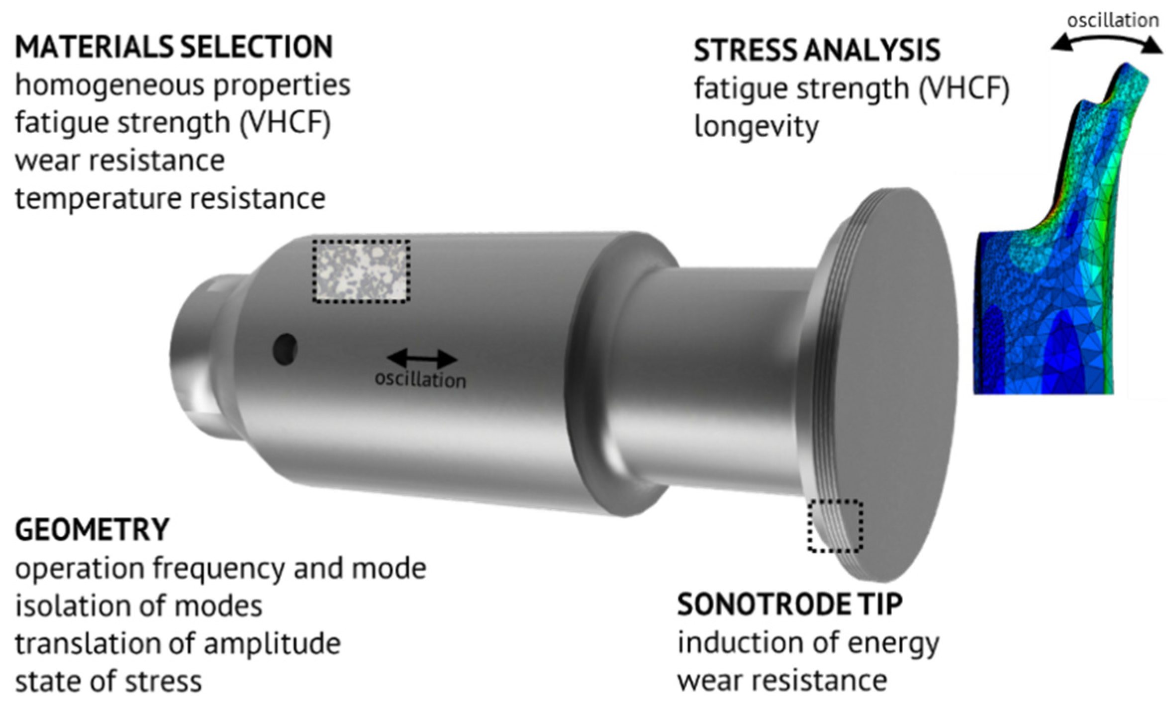
:1. Introduction
2. Materials and Methods
- Materials selection
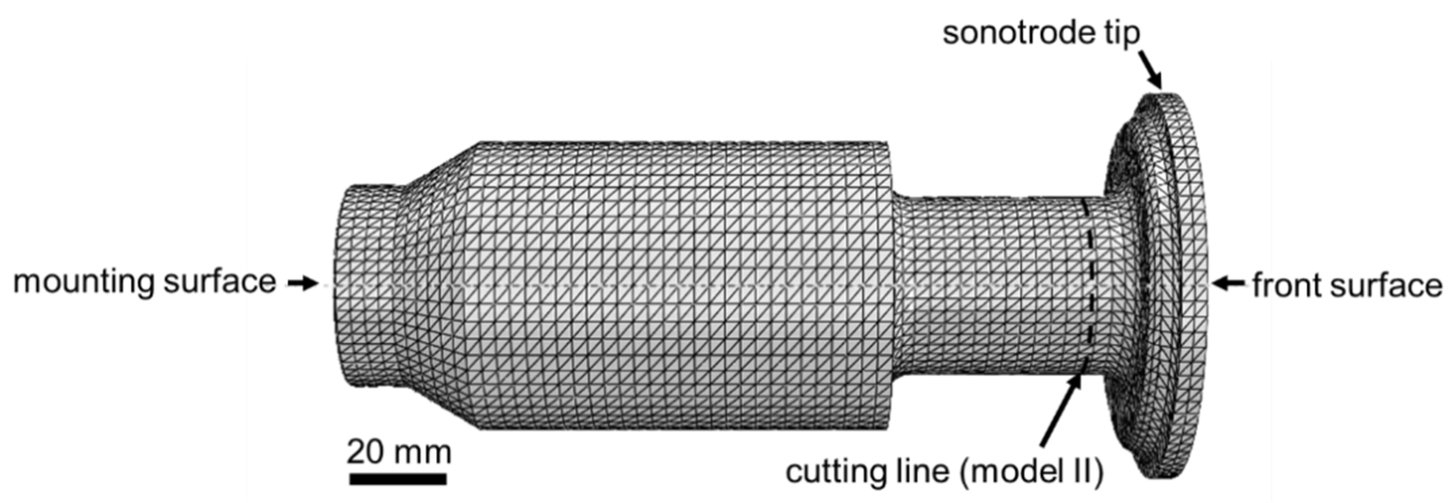
- Design of the sonotrode geometry:
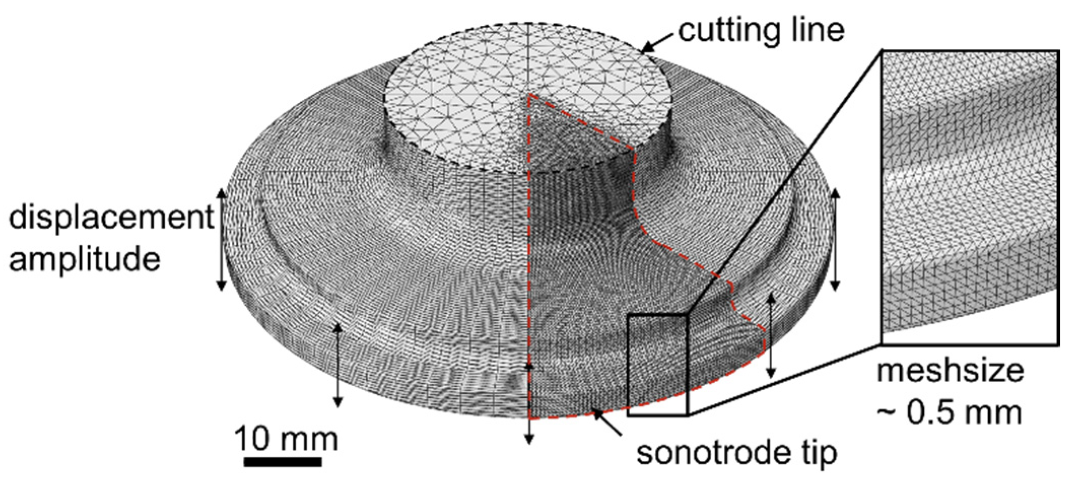
- Theoretical modal analysis (FEM model I)
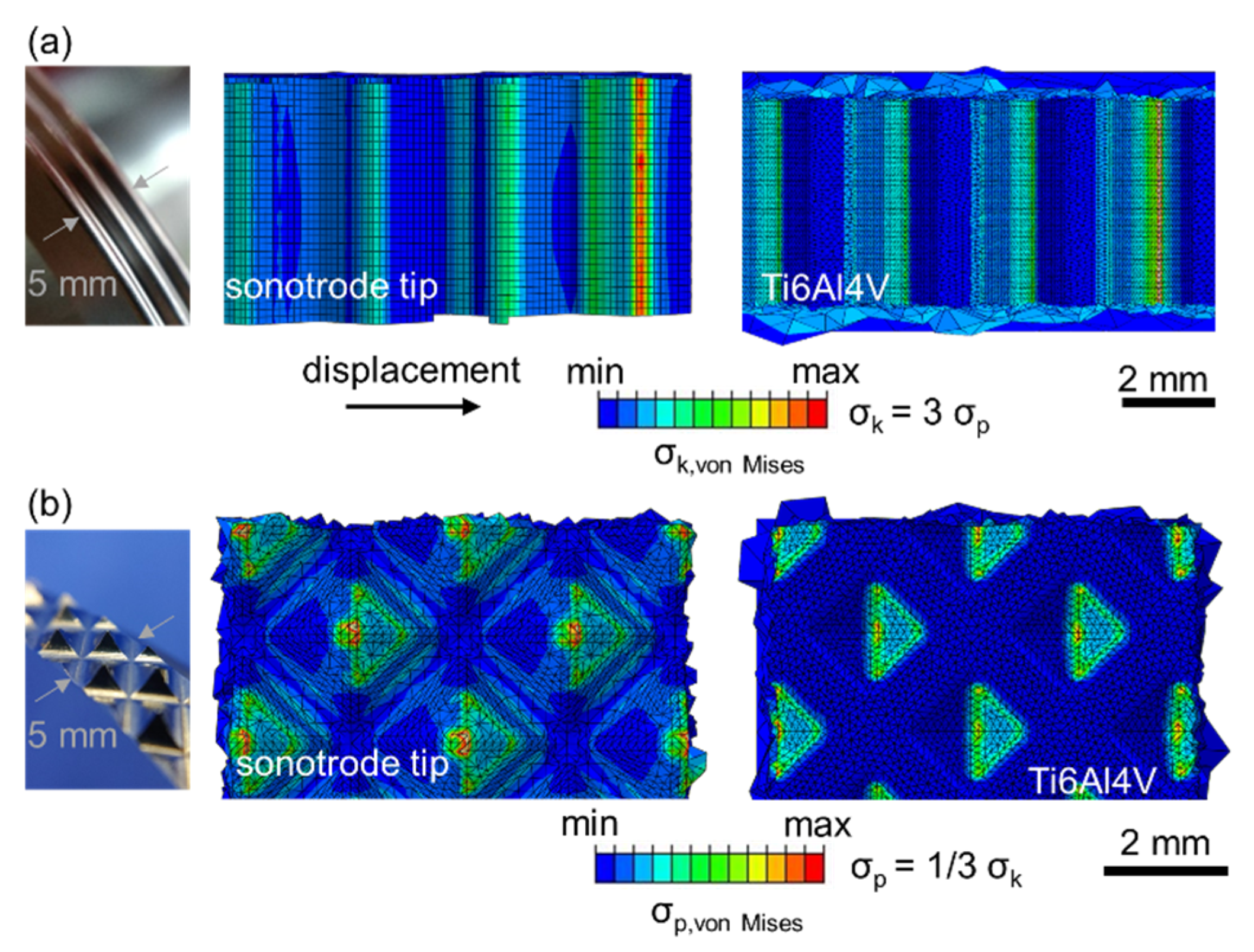
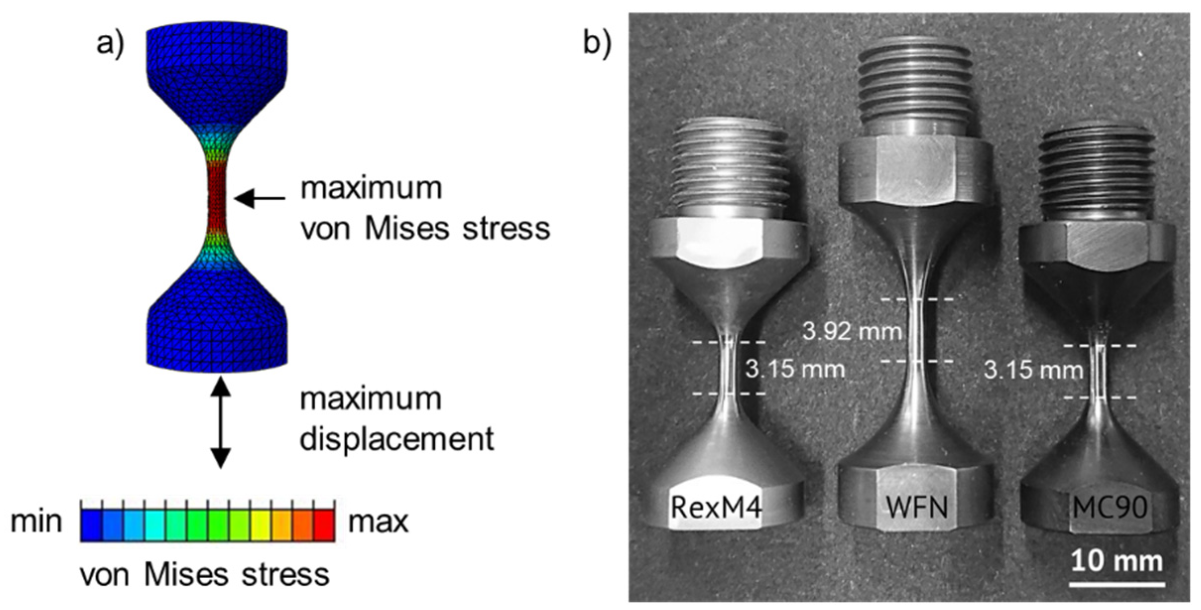
- Calculation of mechanical stresses (FEM model II)
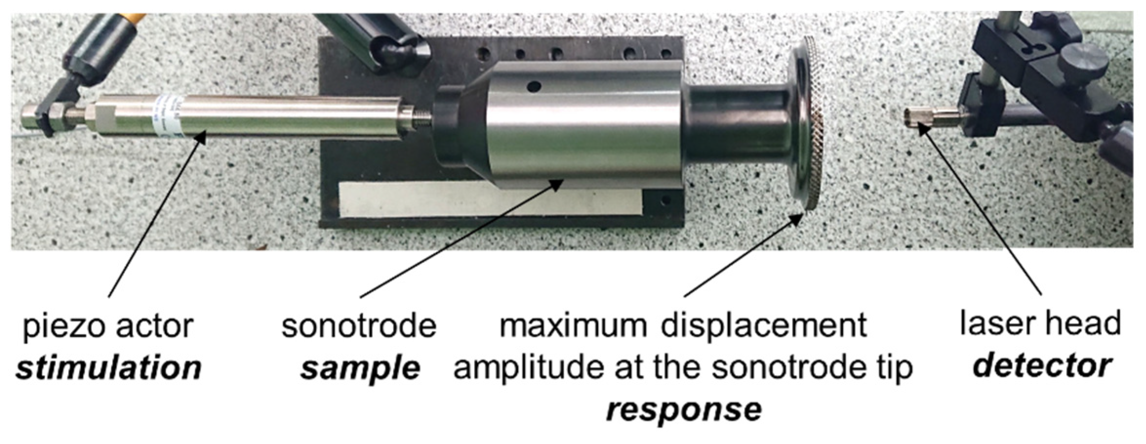
- Experimental modal analysis and validation of the oscillation behaviour
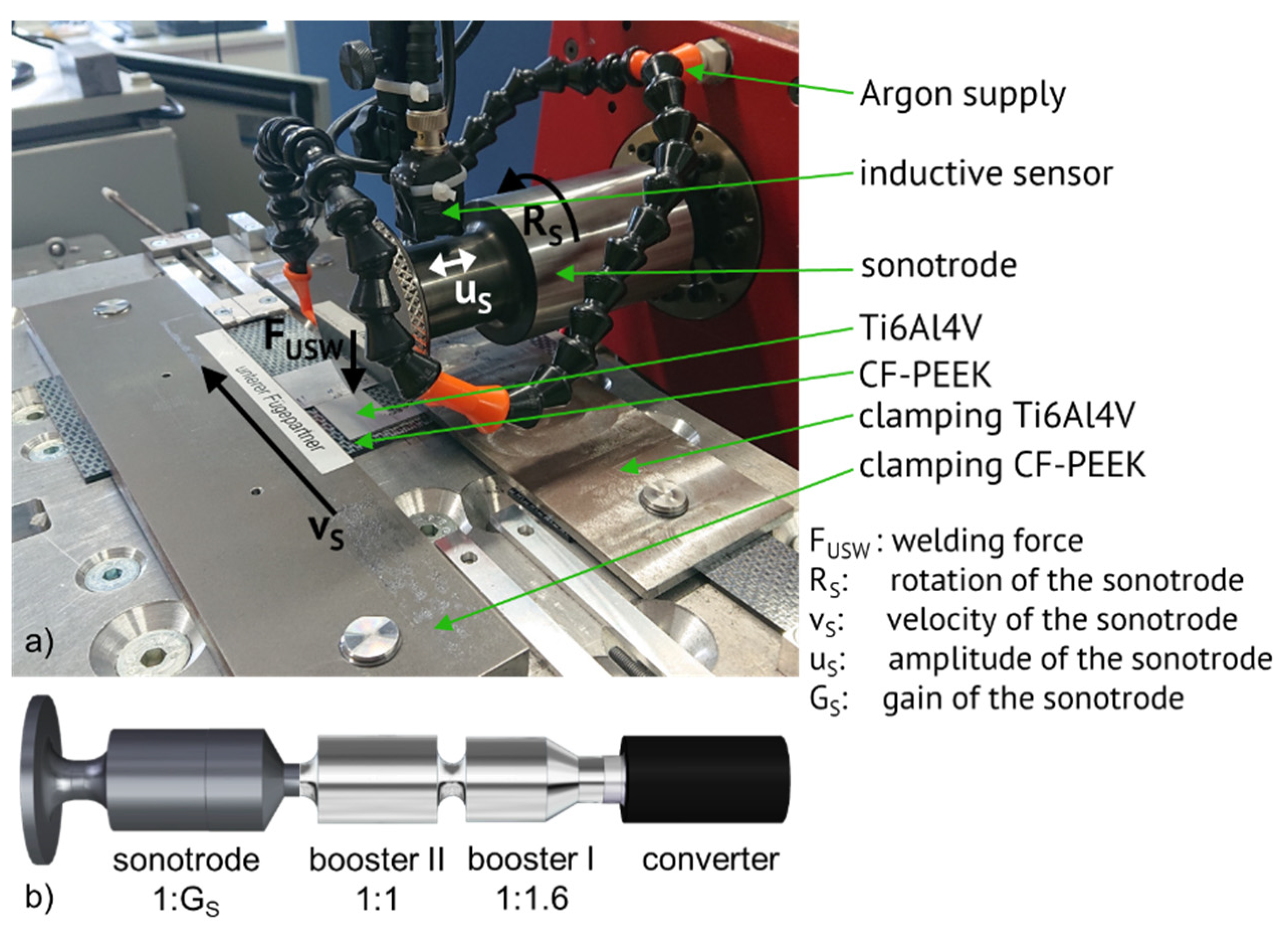
- Welding experiments
2.1. Materials Selection and Characterization
2.2. Design of the Sonotrode Geometry
2.3. Modal Analysis
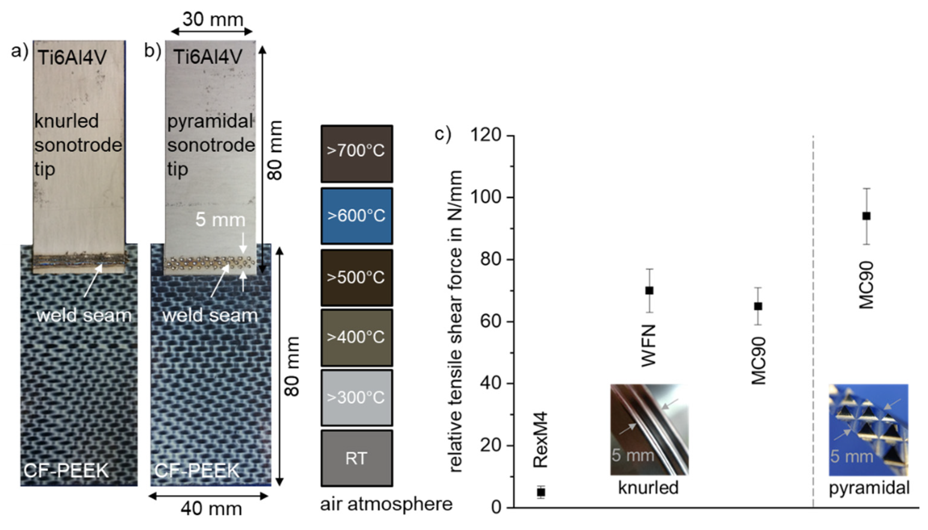
2.4. Welding Experiments and Mechanical Testing
3. Sonotrode Development and Results
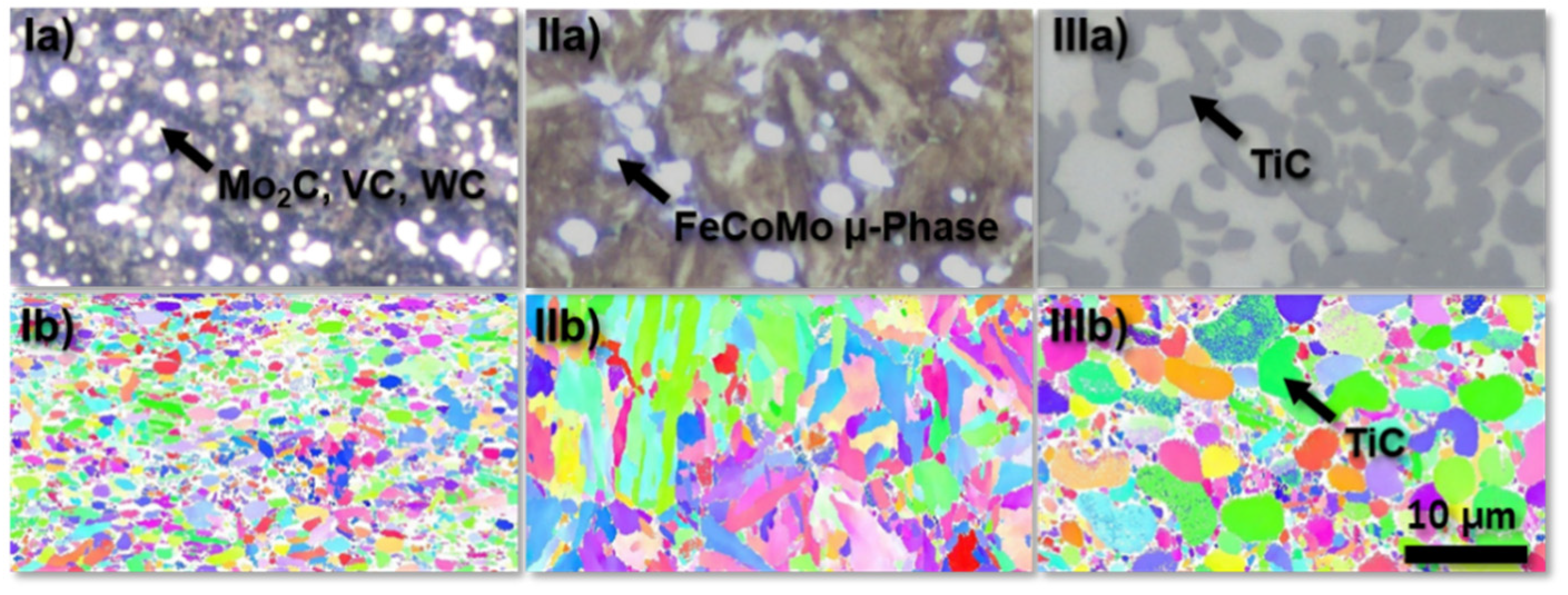
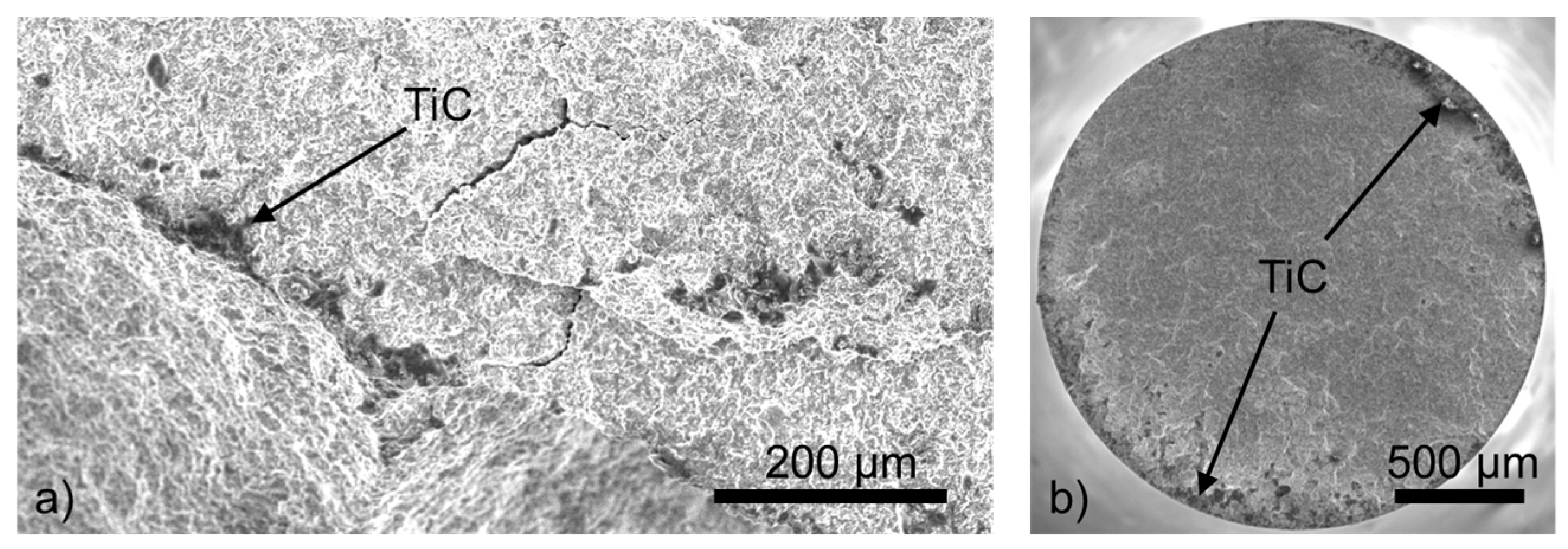
3.1. Materials Selection
3.2. Design of the Sonotrode Geometry
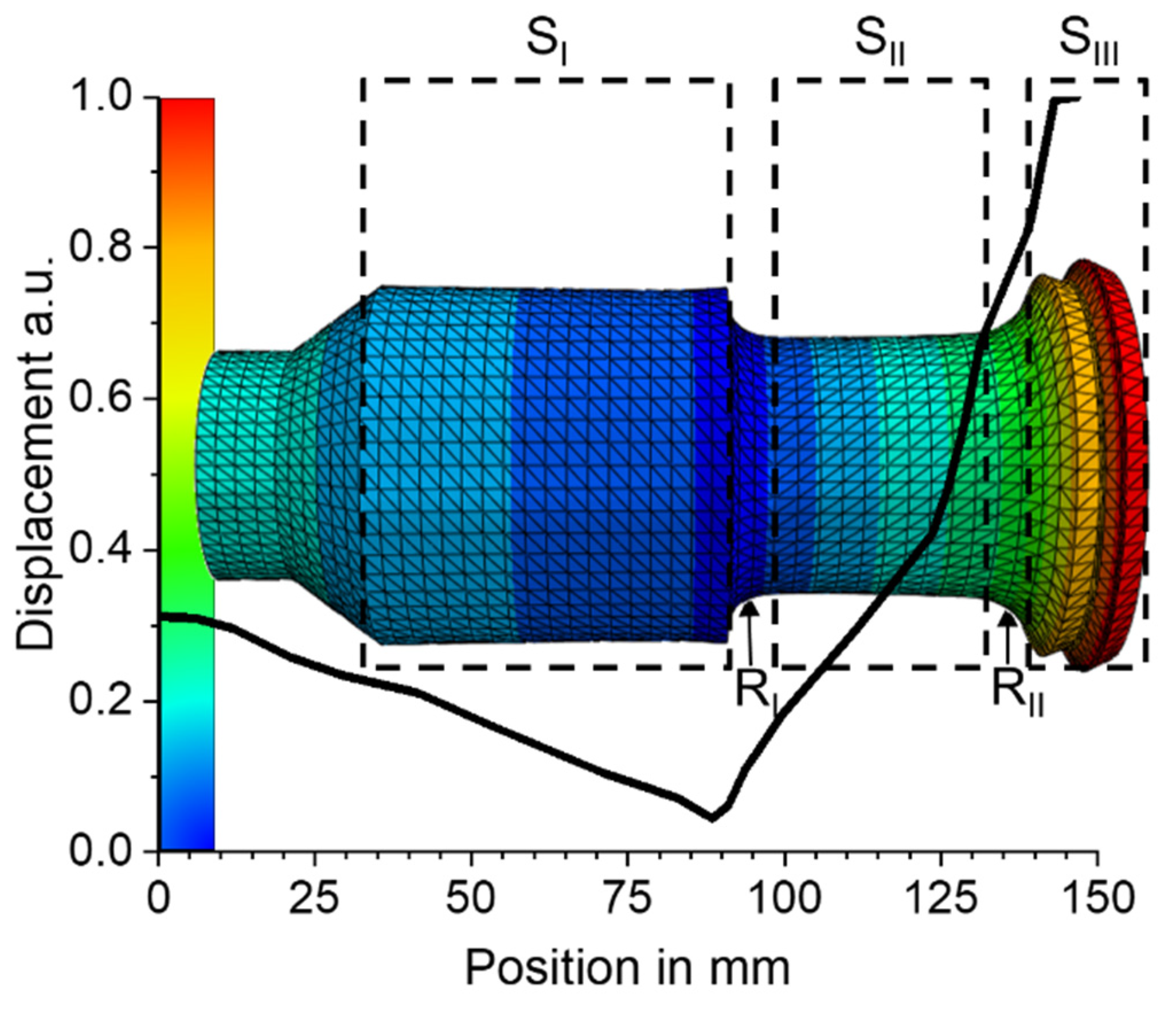
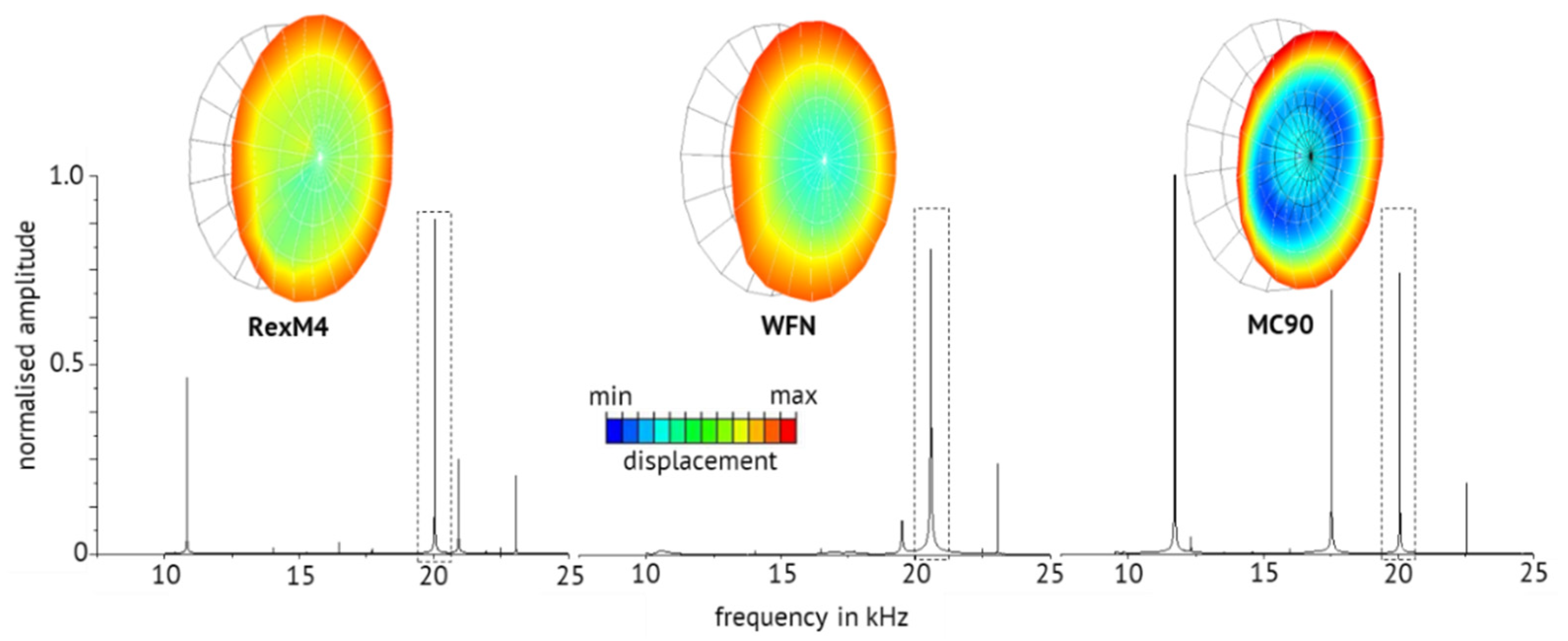
3.2.1. Modal Frequency and Modal Shape of the Operational Mode
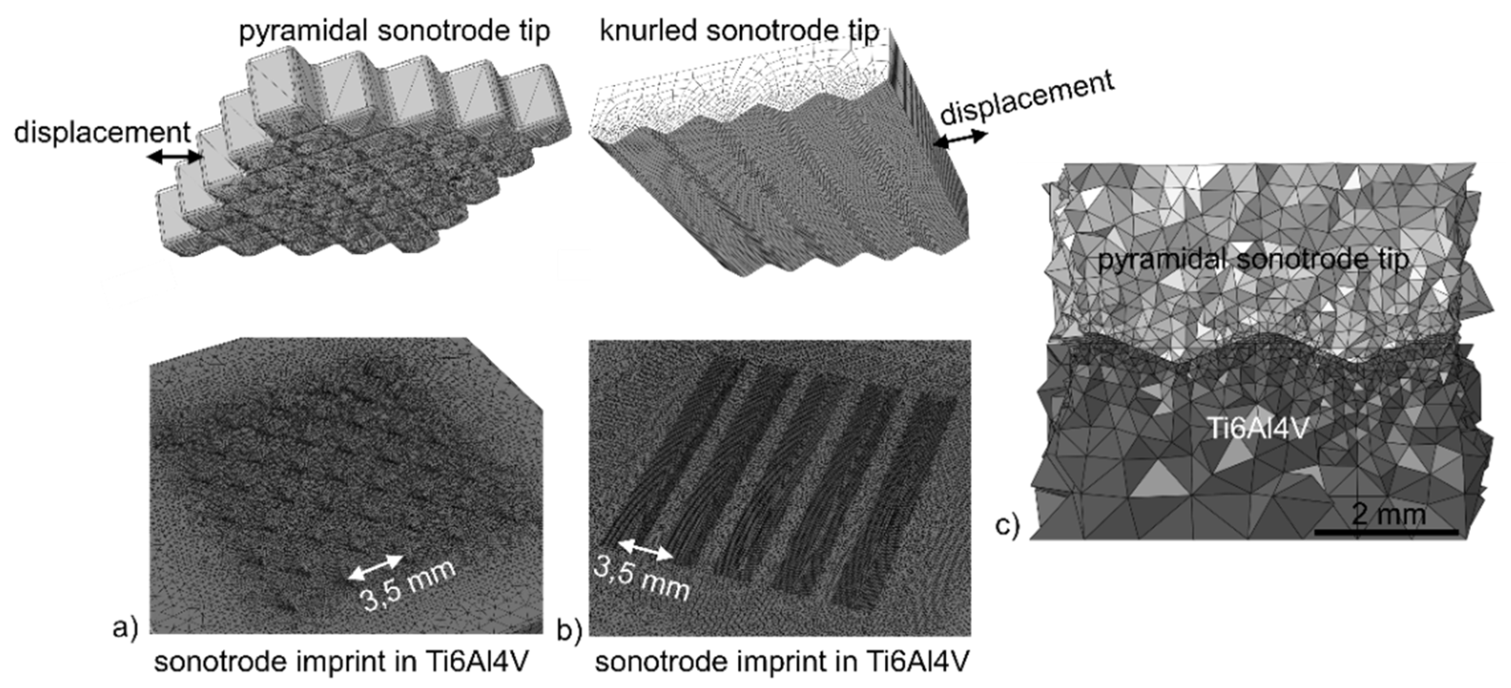
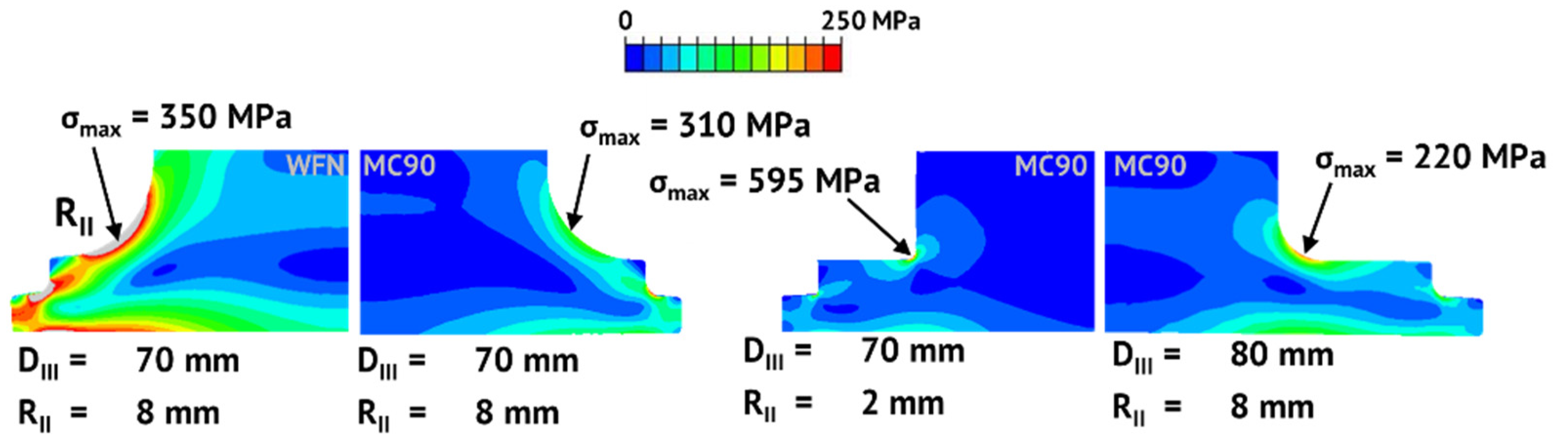
3.2.2. Mechanical Stresses Relating to Displacement Amplitude at the Sonotrode Tip
3.3. Modal Analysis
3.4. Sonotrode Suitability for Ultrasonic Welding of Ti6Al4V to CF-PEEK
4. Summary
Supplementary Materials
Author Contributions
Funding
Institutional Review Board Statement
Informed Consent Statement
Data Availability Statement
Acknowledgments
Conflicts of Interest
References
- Amancio-Filho, S.T.; Blaga, L.-A. Joining of Polymer-Metal Hybrid Structures; John Wiley & Sons, Inc.: Hoboken, NJ, USA, 2018; ISBN 9781119429807. [Google Scholar]
- Lambiase, F.; Balle, F.; Blaga, L.-A.; Liu, F.; Amancio-Filho, S.T. Friction-based processes for hybrid multi-material joining. Compos. Struct. 2021, 266, 113828. [Google Scholar] [CrossRef]
- Villegas, I.F. Strength development versus process data in ultrasonic welding of thermoplastic composites with flat energy directors and its application to the definition of optimum processing parameters. Compos. Part A Appl. Sci. Manuf. 2014, 65, 27–37. [Google Scholar] [CrossRef]
- Harman, G.; Albers, J. The Ultrasonic Welding Mechanism as Applied to Aluminum-and Gold-Wire Bonding in Microelectronics. IEEE Trans. Parts Hybrids Packag. 1977, 13, 406–412. [Google Scholar] [CrossRef]
- Staab, F.; Balle, F. Ultrasonic torsion welding of ageing-resistant Al/CFRP joints: Properties, microstructure and joint formation. Ultrasonics 2019, 93, 139–144. [Google Scholar] [CrossRef]
- Balle, F.; Wagner, G.; Eifler, D. Ultrasonic Metal Welding of Aluminium Sheets to Carbon Fibre Reinforced Thermoplastic Composites. Adv. Eng. Mater. 2009, 11, 35–39. [Google Scholar] [CrossRef]
- Balle, F.; Eifler, D. Statistical test planning for ultrasonic welding of dissimilar materials using the example of aluminum-carbon fiber reinforced polymers (CFRP) joints. Mat. Wiss. U. Werkst. 2012, 43, 286–292. [Google Scholar] [CrossRef]
- Magin, J.; Balle, F. Solid state joining of aluminum, titanium and their hybrids by ultrasonic torsion welding. Mat. Wiss. Werkst. 2014, 45, 1072–1083. [Google Scholar] [CrossRef]
- Fujii, H.T.; Goto, Y.; Sato, Y.S.; Kokawa, H. Microstructure and lap shear strength of the weld interface in ultrasonic welding of Al alloy to stainless steel. Scr. Mater. 2016, 116, 135–138. [Google Scholar] [CrossRef]
- Shimizu, S.; Fujii, H.T.; Sato, Y.S.; Kokawa, H.; Sriraman, M.R.; Babu, S.S. Mechanism of weld formation during very-high-power ultrasonic additive manufacturing of Al alloy 6061. Acta Mater. 2014, 74, 234–243. [Google Scholar] [CrossRef]
- Watanabe, T.; Sakuyama, H.; Yanagisawa, A. Ultrasonic welding between mild steel sheet and Al–Mg alloy sheet. J. Mater. Process. Technol. 2009, 209, 5475–5480. [Google Scholar] [CrossRef]
- Patel, V.K.; Bhole, S.D.; Chen, D.L. Ultrasonic spot welded AZ31 magnesium alloy: Microstructure, texture, and lap shear strength. Mater. Sci. Eng. A 2013, 569, 78–85. [Google Scholar] [CrossRef]
- Panteli, A.; Robson, J.D.; Brough, I.; Prangnell, P.B. The effect of high strain rate deformation on intermetallic reaction during ultrasonic welding aluminium to magnesium. Mater. Sci. Eng. A 2012, 556, 31–42. [Google Scholar] [CrossRef] [Green Version]
- Liesegang, M.; Arweiler, S.; Beck, T.; Balle, F. Orbital Ultrasonic Welding of Ti-Fittings to CFRP-Tubes. J. Manuf. Mater. Process. 2021, 5, 30. [Google Scholar] [CrossRef]
- Zhang, C.; Robson, J.D.; Haigh, S.J.; Prangnell, P.B. Interfacial Segregation of Alloying Elements During Dissimilar Ultrasonic Welding of AA6111 Aluminum and Ti6Al4V Titanium. Met. Mat. Trans. A 2019, 50, 5143–5152. [Google Scholar] [CrossRef] [Green Version]
- Neppiras, E.A. Very high energy ultrasonics. Br. J. Appl. Phys. 1960, 11, 143–150. [Google Scholar] [CrossRef]
- Amin, S.G.; Ahmed, M.H.M.; Youssef, H.A. Computer-aided design of acoustic horns for ultrasonic machining using finite-element analysis. J. Mater. Process. Technol. 1995, 55, 254–260. [Google Scholar] [CrossRef]
- Derks, P.P. The Design of Ultrasonic Resonators with Wide Output Cross-Sections. Ph.D. Thesis, Technische Hogeschool Eindhoven, Eindhoven, The Netherlands, 1984. [Google Scholar] [CrossRef]
- Stănăşel, I.; Buidoş, T.; Blaga, F. Design and FEM simulation of ultrasonic welding horn. Rom. Assoc. Nonconv. Technol. 2014, 18, 51–55. [Google Scholar]
- Nanu, A.S. Study on ultrasonic stepped horn geometry design and FEM simulation. Nonconv. Technol. Rev. 2011, 4/2011, 25–30. [Google Scholar]
- Roopa Rani, M.; Rudramoorthy, R. Computational modeling and experimental studies of the dynamic performance of ultrasonic horn profiles used in plastic welding. Ultrasonics 2013, 53, 763–772. [Google Scholar] [CrossRef]
- Lin, S.; Guo, H.; Xu, J. Actively adjustable step-type ultrasonic horns in longitudinal vibration. J. Sound Vib. 2018, 419, 367–379. [Google Scholar] [CrossRef]
- Emmer, Š.; Kováčik, J.; Baksa, P. Effect of microstructure on the sonotrode properties of tool materials Ferro-titanit® WFN and steel CPM 10V®. Met. Mater. 2016, 53, 423–428. [Google Scholar] [CrossRef] [Green Version]
- Emmer, Š.; Kováčik, J.; Mrkvová, S. Materials for sonotrode tools. Sci. Proc. Fac. Mech. Eng. STU Bratisl. 2013, 21, 503. [Google Scholar] [CrossRef] [Green Version]
- Thorby, D. Structural Dynamics and Vibration in Practice: An Engineering Handbook; Butterworth-Heinemann: Oxford, UK, 2008; ISBN 9780080557151. [Google Scholar]
- Lucas, M.; Cardoni, A.; Lim, F.C.N.; Cartmell, M.P.; McGeough, J.A. Effects of Modal Interactions on Vibration Performance in Ultrasonic Cutting. CIRP Ann. 2003, 52, 193–196. [Google Scholar] [CrossRef]
- Lucas, M.; Petzing, J.N.; Cardoni, A.; Smith, L.J.; McGeough, J.A. Design and Characterisation of Ultrasonic Cutting Tools. CIRP Ann. 2001, 50, 149–152. [Google Scholar] [CrossRef]
- Cardoni, A.; Lucas, M. Enhanced vibration performance of ultrasonic block horns. Ultrasonics 2002, 40, 365–369. [Google Scholar] [CrossRef]
- Cardoni, A.; Lucas, M.; Cartmell, M.; Lim, F. A novel multiple blade ultrasonic cutting device. Ultrasonics 2004, 42, 69–74. [Google Scholar] [CrossRef]
- Budairi, H.D. Design and Analysis of Ultrasonic Horns Operating in Longitudinal and Torsional Vibration. PhD Thesis, University of Glasgow, Glasgow, UK, , 2012. Unique ID: Glathesis:2012-3851. [Google Scholar]
- Brouet, F.; Twiefel, J.; Wallaschek, J. Modal interaction in ultrasonic welding block sonotrodes induced by the mistuning of the material properties. J. Sound Vib. 2016, 381, 1–13. [Google Scholar] [CrossRef]
- Harkness, P.; Lucas, M.; Cardoni, A. Coupling and degenerating modes in longitudinal-torsional step horns. Ultrasonics 2012, 52, 980–988. [Google Scholar] [CrossRef]
- Tsujino, J.; Ueoka, T.; Kashino, T.; Sugahara, F. Transverse and torsional complex vibration systems for ultrasonic seam welding of metal plates. Ultrasonics 2000, 38, 67–71. [Google Scholar] [CrossRef]
- Tsujino, J.; Harada, Y.; Ihara, S.; Kasahara, K.; Shimizu, M.; Ueoka, T. Configurations of high-frequency ultrasonics complex vibration systems for packaging in microelectronics. Ultrasonics 2004, 42, 125–129. [Google Scholar] [CrossRef]
- Tsujino, J.; Ueoka, T. Ultrasonic Seam Welding System Using a Complex Vibration Circular Disk in Transverse and Torsional Vibrations. Jpn. J. Appl. Phys. 1999, 38, 3307–3311. [Google Scholar] [CrossRef]
- Smaga, M.; Boemke, A.; Daniel, T.; Skorupski, R.; Sorich, A.; Beck, T. Fatigue Behavior of Metastable Austenitic Stainless Steels in LCF, HCF and VHCF Regimes at Ambient and Elevated Temperatures. Metals 2019, 9, 704. [Google Scholar] [CrossRef] [Green Version]
- Beck, T.; Kovacs, S.A.; Ritz, F. VHCF Behavior and Word Hardening of a Ferritic-Martensitic Steel at High Mean Stresses. Key Eng. Mater. 2015, 664, 246–254. [Google Scholar] [CrossRef]
- Nad, M. Ultrasonic horn design for ultrasonic machining technologies. Appl. Comput. Mech. 2010, 4, 79–88. [Google Scholar]
- Chen, K.; Zhang, Y. Mechanical analysis of ultrasonic welding considering knurl pattern of sonotrode tip. Mater. Des. 2015, 87, 393–404. [Google Scholar] [CrossRef]
- Qu, J.; Blau, P.J.; Watkins, T.R.; Cavin, O.B.; Kulkarni, N.S. Friction and wear of titanium alloys sliding against metal, polymer, and ceramic counterfaces. Wear 2005, 258, 1348–1356. [Google Scholar] [CrossRef]
- CES Edupack; Granta Design: Cambridge, UK, 2018.
- MC90 Intermet: Datasheet; Böhler voestalpine: Kapfenberg, Austria, 2019.
- CPM RexM4: Datasheet; Zapp Materials Engineering GmbH: Ratingen, Germany, 2016.
- Ferrotitanit: Datasheet; Deutsche Edelstahlwerke Specialty Steel GmbH & Co. KG: Krefeld, Germany, 2020.
- Foller, M. A new investigation on mechanical properties of ferro-titanit. In Proceedings of the 6th International Tooling Conferece, Karlstadt, Swede, 10–13 September 2002; pp. 1373–1389. [Google Scholar]
- CPM 10V: Datasheet; Zapp Materials Engineering GmbH: Ratingen, Germany, 2016.
- Furuya, Y.; Matsuoka, S.; Shimakura, S.; Hanamura, T.; Torizuka, S. Fatigue Strength of Ultrafine Ferrite-Cementite Steels and Effects of Strengthening Mechanisms. Met. Mat. Trans. A 2007, 38, 2984–2991. [Google Scholar] [CrossRef]
- Hamada, A.S.; Karjalainen, L.P. High-cycle fatigue behavior of ultrafine-grained austenitic stainless and TWIP steels. Mater. Sci. Eng. A 2010, 527, 5715–5722. [Google Scholar] [CrossRef]
- Chawla, N.; Shen, Y.-L. Mechanical Behavior of Particle Reinforced Metal Matrix Composites. Adv. Eng. Mater. 2001, 3, 357–370. [Google Scholar] [CrossRef]


| Ti6Al4V [41] | Sonotrode Tip [42] | |
|---|---|---|
| Young’s modulus in GPa | 110.0 | 223.3 (MC90) |
| Poisson’s ratio | 0.34 | 0.20 (MC90) |
| Friction coefficient | 0.5 [40] | |
| Fe | C | Mn | Si | Cr | V | Mo | W |
|---|---|---|---|---|---|---|---|
| 79.3% | 1.4% | 0.3% | 0.3% | 4% | 4% | 5.2% | 5.5% |
| Steelmatrix (67%) | Ceramic Phase (33%) | |||
|---|---|---|---|---|
| Fe | C | Cr | Mo | TiC |
| 82.75% | 0.75% | 13.5% | 3.0% | 100% |
| Fe | Si | Mn | Mo | Co |
|---|---|---|---|---|
| 59.2% | 0.6% | 0.2% | 15% | 25% |
| RexM4 [43] | WFN [44] | MC90 [42,45] | |
|---|---|---|---|
| Hardness HRC | 64 | 69 | 68 |
| Young’s Modulus in GPa | 214 | 294 | 223 |
| Mass density in g/cm3 | 7.97 | 6.5 | 8.28 |
| Poisson’s ratio | 0.3 | 0.24 | 0.2 |
| Machinability | + | – – | – |
| Materials | MC90 | WFN | RexM4 |
|---|---|---|---|
| Fatigue strength at 2.5 × 10⁹ load cycles in MPa | 430 | 380 | 413 |
| RexM4 | WFN | MC90 | |
|---|---|---|---|
| Grain size in µm | 1–3 | 0.3–3 | 3–6 |
| Size of reinforcing phase in µm | 1–2 | 5–8 | 1–3 |
| Content of reinforcing phase in area% | 20 | 33 | 6 |
| Modal Frequency in Hz | Transmission of the Sonotrode | |||
|---|---|---|---|---|
| fi Initial | fa Annealed | fi-fa | 1:G | |
| RexM4 | 20,540 | 20,035 | 505 | 1:2.81 |
| WFN | 20,500 | 20,230 | 270 | 1:2.67 |
| MC90 | 20,700 | 20,030 | 670 | 1:3.13 |
Publisher’s Note: MDPI stays neutral with regard to jurisdictional claims in published maps and institutional affiliations. |
© 2021 by the authors. Licensee MDPI, Basel, Switzerland. This article is an open access article distributed under the terms and conditions of the Creative Commons Attribution (CC BY) license (https://creativecommons.org/licenses/by/4.0/).
Share and Cite
Liesegang, M.; Yu, Y.; Beck, T.; Balle, F. Sonotrodes for Ultrasonic Welding of Titanium/CFRP-Joints—Materials Selection and Design. J. Manuf. Mater. Process. 2021, 5, 61. https://doi.org/10.3390/jmmp5020061
Liesegang M, Yu Y, Beck T, Balle F. Sonotrodes for Ultrasonic Welding of Titanium/CFRP-Joints—Materials Selection and Design. Journal of Manufacturing and Materials Processing. 2021; 5(2):61. https://doi.org/10.3390/jmmp5020061
Chicago/Turabian StyleLiesegang, Moritz, Yuan Yu, Tilmann Beck, and Frank Balle. 2021. "Sonotrodes for Ultrasonic Welding of Titanium/CFRP-Joints—Materials Selection and Design" Journal of Manufacturing and Materials Processing 5, no. 2: 61. https://doi.org/10.3390/jmmp5020061
APA StyleLiesegang, M., Yu, Y., Beck, T., & Balle, F. (2021). Sonotrodes for Ultrasonic Welding of Titanium/CFRP-Joints—Materials Selection and Design. Journal of Manufacturing and Materials Processing, 5(2), 61. https://doi.org/10.3390/jmmp5020061