Communication

Pressing and Infiltration of Metal Matrix Nanocomposites

1
Department of Engineering Technology and Industrial Distribution, Texas A&M University, College Station, TX 77843, USA
2
Department of Mechanical Engineering, Texas A&M University, College Station, TX 77843, USA
3
Department of Mechanical and Aerospace Engineering, University of California, Los Angeles, CA 90095, USA
*
Author to whom correspondence should be addressed.
J. Manuf. Mater. Process. 2021, 5(2), 54; https://doi.org/10.3390/jmmp5020054
Submission received: 25 April 2021 / Revised: 16 May 2021 / Accepted: 25 May 2021 / Published: 28 May 2021
(This article belongs to the Special Issue Powder Metallurgy and Additive Manufacturing/3D Printing of Materials)

Abstract

:
The ability to produce metal matrix nanocomposites via pressing and infiltration was validated. Al/TiC nanocomposite was used as the model material. Pressing the powder in a die yielded cylindrical specimens with a green density of 1.98 ± 0.05 g/cm3, which was increased to only 2.11 ± 0.12 g/cm3 by sintering. Direct infiltration of the pressed specimens at 1050 °C for 3.5 h yielded specimens with a density of 3.07 ± 0.08 g/cm3, an open porosity of 3.06 ± 1.40%, and an areal void fraction of 8.09 ± 2.67%. The TiC nanoparticles were verified to be well dispersed using energy-dispersive X-ray spectroscopy. The measured hardness of 64 ± 3 HRA makes it a promising material for structural applications in industries such as aerospace and automotive.

1. Introduction

Aluminum reinforced with ceramic microparticles becomes a metal matrix composite (MMC) with an excellent strength-to-weight ratio [1]. There are a multitude of ceramic reinforcements, such as Al2O3, SiC, TiN, and TiC, to enhance wear resistance, stiffness, and strength in composites for structural applications in aerospace and automobile industries [2,3,4]. The machining of these aluminum matrix composites is a difficult task due to the superior mechanical properties of the material wearing the tools. A common solution is the use of powder metallurgy to make near-net-shape parts from powder, which drastically reduces the need for post-machining [5]. Using a die, the feedstock powder can be pressed into a green part before sintering; however, the aluminum particle matrix presents issues for sintering.
Research shows that the porosity of the sintered aluminum product after pressing is often not acceptable for the intended use because of the poor sinterability resulting from surface oxidation [6,7]. Investigations into the manufacturing of aluminum matrix composites have often resulted in the inability to achieve full density from sintering alone [8]. To reduce the porosities of the parts, infiltration can be used. Infiltration involves wicking molten material into the voids within a preform that does not melt at the temperature required to melt the infiltrating material [9]. Cramer et al. verified that aluminum matrix composites such as Al/B4C can be manufactured by infiltrating a ceramic preform under vacuum, and relative densities of nearly 97% were achieved in their research [10]. A multitude of Al-alloys have been used to infiltrate preforms of TiC with varying degrees of success, from poor shape retention with high residual porosity to near fully dense structures that have minimal shrinkage and can be deemed near-net-shape [11,12]. Aguilar et al. found that Al-alloys have good wettability with TiC despite pure Al-1010 showing the greatest wettability as validated by the highest rate of infiltration in comparison to the investigated Al-alloys [11].
The use of nanoparticles to make preforms for infiltration is not common. The previous use of melt infiltration to manufacture MMCs has used microparticles to compose preforms [5,10,13,14], leaving a void in research on nanoparticle-reinforced MMCs or metal matrix nanocomposites (MMNCs). Introducing nanoparticles to the metal matrix as reinforcement agents has consistently shown that they improve material properties [15,16,17,18]. The advantages of nanoparticles over larger particles even in the micrometer range include higher strength attributed to larger local dislocation densities and refined grain size [16]. Other benefits are the improved homogeneity of the parts that aid in increased mechanical properties [19]. Because the mechanical properties can be achieved more readily with nanoparticles, a lower volume percentage of reinforcement is needed, which can keep the density from increasing and retain more ductility than alternative methods of strengthening [20]. This investigation aims to determine whether a preform made of Al with dispersed TiC nanoparticles can be manufactured and then infiltrated with Al-6061 as though it were a cermet by utilizing the tendency for the surface of Al to naturally oxidize. The theorized result of the process is an aluminum matrix nanocomposite with density, hardness, strength, and properties to be characterized and measured.

2. Experimental Methods

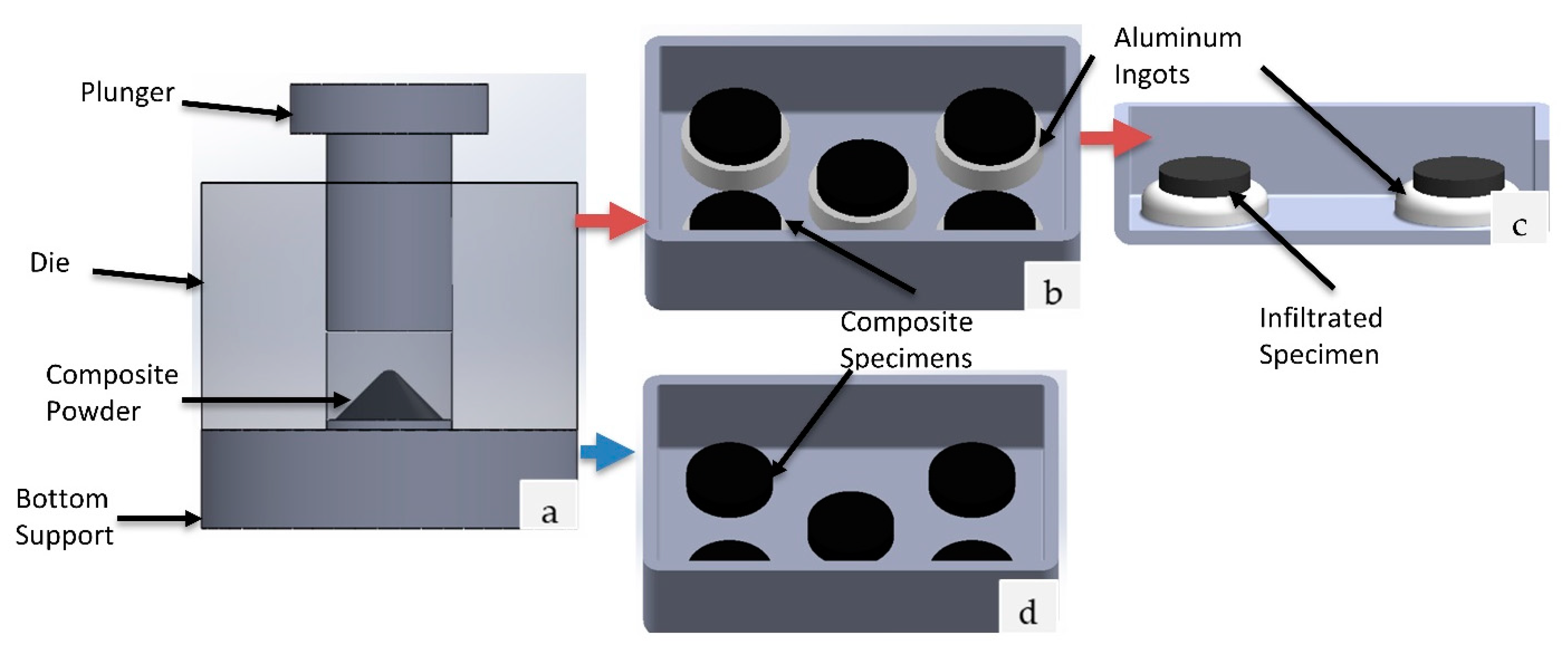
2.1. Specimen Preparation

The Al/TiC powder composed of 35 vol.% TiC nanoparticles and 65 vol.% pure Al was prepared following the method documented in a previous publication [21]. After preparing the powder that consists of spherical particles, it was sieved mechanically to obtain a size range of 20–40 μ m. Cold pressed specimens of 13.08 ± 0.02 mm diameter were created by placing 1 g of powder into a steel die, displayed in Figure 1a, under a pressure of 300 MPa. The cylindrical specimens were stored in a silica bead desiccant for a minimum of 24 h prior to use to remove any water.
Preliminary investigations proved that the pressed specimens maintain their initial shape at temperatures exceeding 1100 °C because the aluminum particles have an oxide layer that naturally forms on the surface. This characteristic allowed the direct infiltration of the preformed specimens at 1050 °C, which is about 400 degrees above the melting point for aluminum. The direct infiltration was performed in a quartz tube furnace (Zhengzhou Brother Furnace Co., Zhengzhou, China, Model: XD-1200NT) under a vacuum after an argon purge. To infiltrate, an Al-6061 ingot, which was stored in a desiccant to remove any water, was ground to remove the oxide layer from the surface that was likely to have formed, and the green part was placed above the ingot before insertion into the furnace as shown in Figure 1b. The specimens were placed in the furnace for the following cycle: ramped up from room temperature to 450 °C over 50 min, increased to 1050 °C over 60 min, held at 1050 °C for 210 min, and allowed to slowly cool to room temperature via natural convection. In Figure 1c, the infiltrated specimens are displayed as they appear after the process. Finally, the excess aluminum alloy was removed from the base of the infiltrated specimens. Some of the preforms were simply sintered under the same thermal cycle for a baseline. The specimen that was to be sintered can be seen in Figure 1d in the boat.

2.2. Measurement of Density and Porosity

The bulk density of the green specimens was determined dimensionally using calipers on more than 30 specimens. The bulk densities of 10 infiltrated and 10 sintered specimens were measured using the Archimedes method provided in Equation (1) [22]:
ρ = ρ w m d m w m s
where ρ is the bulk density of the specimen,   ρ w is the density of the water, m d is the dry mass, m w is the wet mass, and m s is the submerged mass. Mass measurements were all obtained using a balance scale with a resolution of 0.001 g. The open porosity ( ϕ ) is calculated by using the measurements used in the Archimedes method as displayed in Equation (2) [22]:
ϕ = m w m d m w m s
The complex interactions among aluminum, titanium, carbon, and the various alloying elements at an elevated temperature make it possible to have intermetallics and carbides form within the matrix; therefore, a relative density dependent on the theoretical density of the powder would be inaccurate. The total porosity was estimated using images of a polished surface of an infiltrated specimen that were captured with an Olympus BX53™ optical microscope (OM) at 20× magnification. Using ImageJ, the images were converted to black and white prior to applying a threshold, which allowed use of the software to measure the pores. By calculating the average areal fraction of the voids throughout the specimen, the porosity was quantified along with the average size of the pores.

2.3. Characterization of Microstructure and Composition

A cold field emission scanning electron microscope (SEM, JEOL JSM-7500F) was used for imaging and an energy-dispersive X-ray spectroscopy (EDS) was used for composition analysis. The microscopy was performed on the fracture surfaces of the specimens for comparison of the infiltrated and sintered specimens. The fracture surfaces were revealed by mechanically breaking the specimen near the centerline. EDS was conducted on the polished surfaces of the specimens to investigate the composition of the infiltrated specimens. The specimens were first ground with SiC sandpapers of grit sizes of 200, 400, 800, and 1500. The polishing was then carried out with three steps: a diamond slurry of 3 μ m, a diamond slurry of 1 μ m, and an alumina slurry of 0.05 μ m.

2.4. Mechanical Testing

The specimens underwent a Rockwell hardness test on a Macromet 3 digital hardness tester. The infiltrated specimens were indented with a diamond indenter under a 60 kg load, using the HRA scale, to obtain their hardness. A minimum of 10 indentations spread well across the surfaces were recorded for the 10 specimens investigated. The sintered specimens required a superficial hardness test, using the H15N scale, with a 1/16” ball indenter and a 15 kg load due to the relatively low hardness and tendency to fracture with a diamond indenter.

3. Results

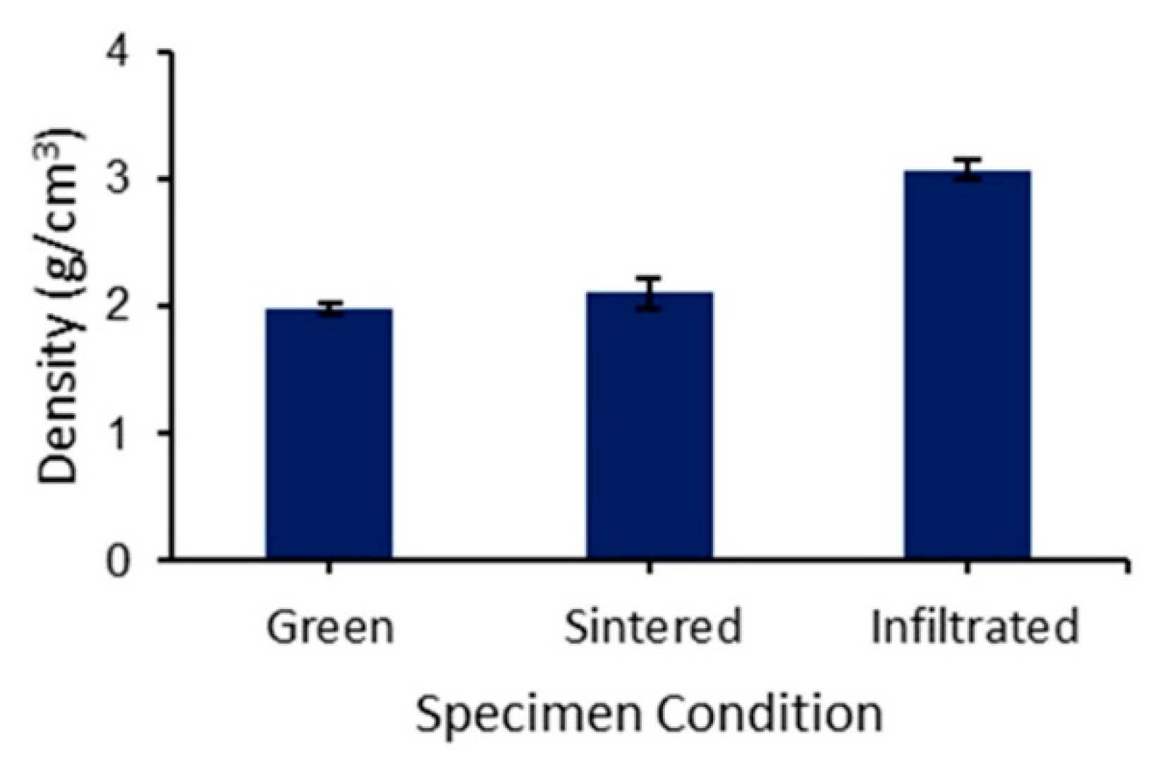
3.1. Density and Porosity

The densities of the specimens after pressing, after sintering, and after infiltration are provided in Figure 2. Sintering the specimens at 1050 °C for 210 min resulted in an average sintered density of 2.11 ± 0.12 g/cm3 from an average green density of 1.98 ± 0.05 g/cm3, which are total porosities of 39.4% and 43.1%, respectively. The increase in density was not significant, and the necessity for infiltration was highlighted. The density of the infiltrated specimens was measured to be 3.07 ± 0.08 g/cm3, while they had a near identical green density to the sintered specimens at 1.97 ± 0.04 g/cm3. The minute standard deviations show a consistent result for the pressing, the sintering, and the infiltration process. Moreover, the Archimedes method showed that the open porosities are 3.06 ± 1.40% and 39.39 ± 1.47% for the infiltrated and sintered specimens, respectively. The low open porosity verifies that infiltration was near its max.
The polished surface of the infiltrated specimen shows that the specimen has an areal void fraction of 8.09 ± 2.67%. The areal void fraction is closely aligned with total porosity, which incorporates both the open and the closed pores within the specimen. The polished surface of the infiltrated specimen is displayed in Figure 3a alongside the processed image used to quantify the areal void fraction shown in Figure 3b. The average pore size of 3.82 ± 1.51 µm2 was also quantified from the optical images. The low areal void fraction and small pore size indicate a successful densification through infiltration.
The infiltration process often requires temperatures that far exceed the melting temperature of the infiltrating material, which is 660 °C for Al, to encourage the kinetics that disperse the molten metal into the voids [23]. The ceramic nature of the preforms allows these temperatures to be reached without noticeable changes to initial geometry through the infiltration or the sintering process. The diameter changed from 13.08 ± 0.02 mm for the green specimens to 12.75 ± 0.04 mm for the infiltrated specimens and 12.76 ± 0.05 mm for the sintered specimens.

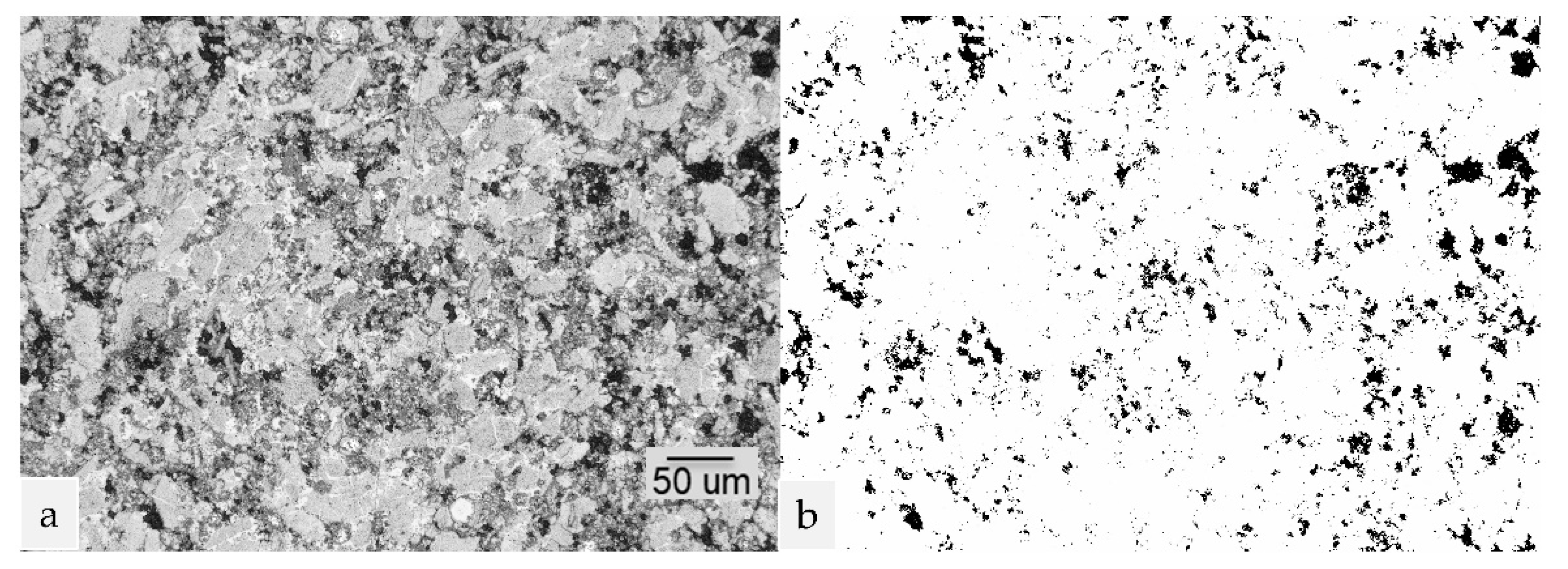
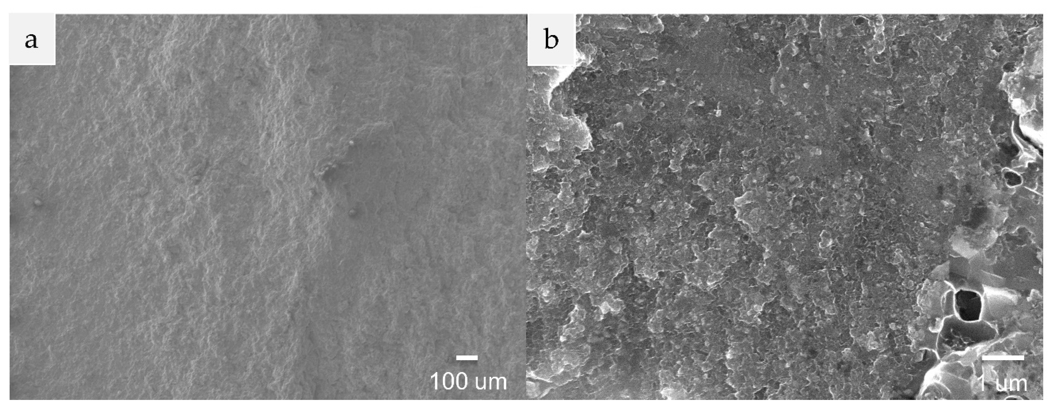
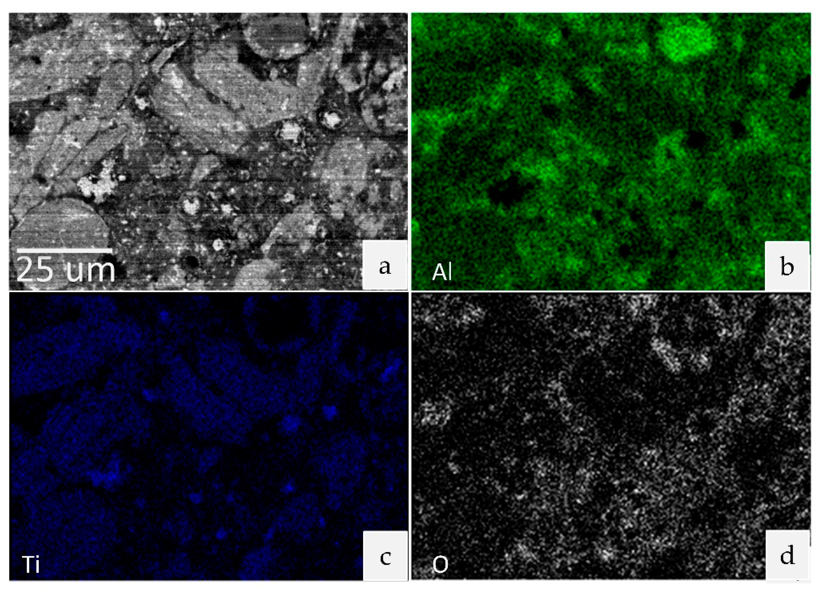
3.2. Microstructure and Composition
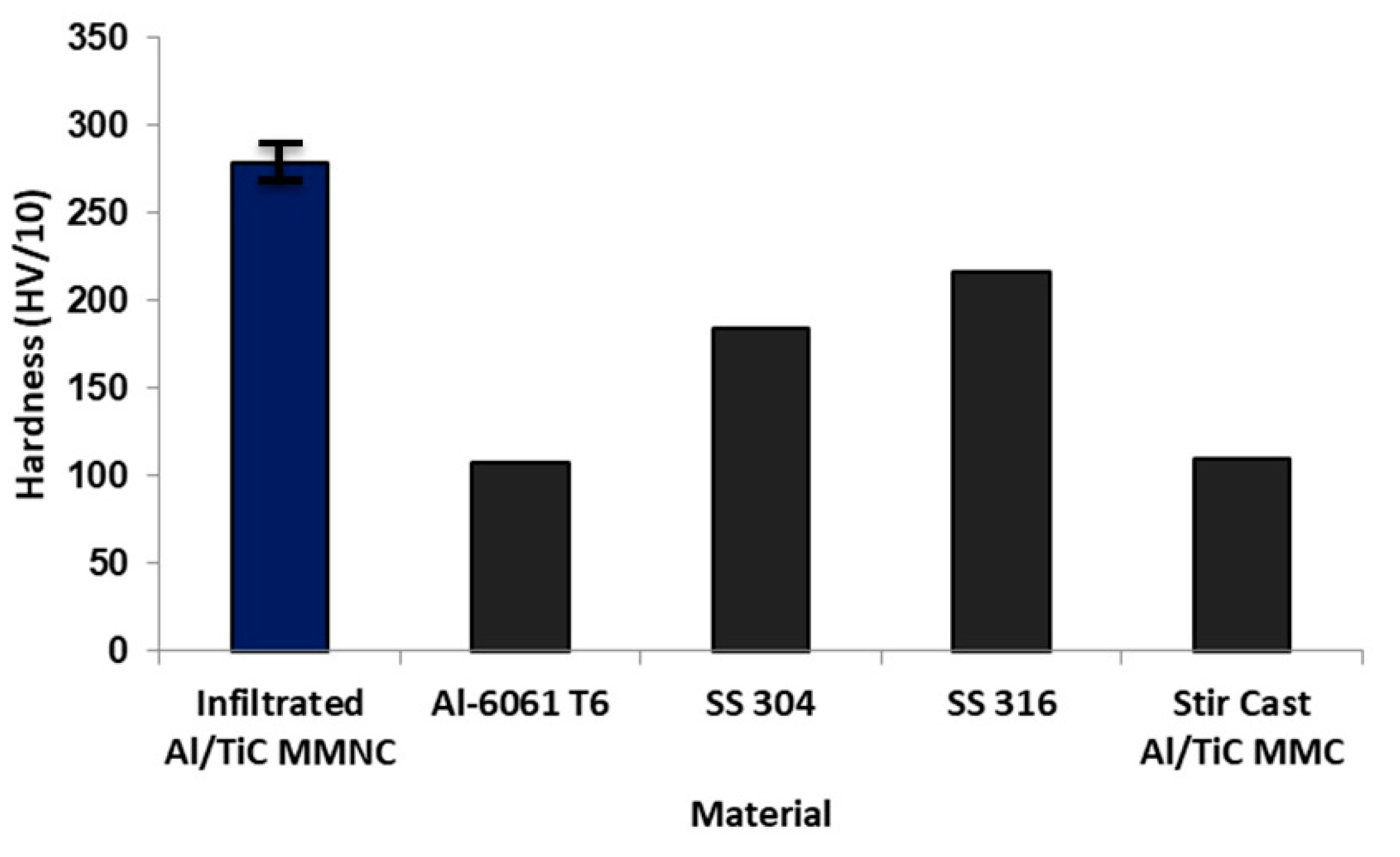
By comparing the fracture surfaces in Figure 4 and Figure 5, the differences between the infiltrated and sintered specimens can be seen. The infiltrated specimen at low magnification in Figure 4a appears dense, and the high magnification in Figure 4b shows very few voids. The sintered specimen has many voids that can be seen in the low-magnification image of Figure 5a, and a clear powder-like microstructure can be seen at the high magnification in Figure 5b. The granular nature within the sintered specimen gives little to no indication of particles merging into a non-porous solid. This is likely due to the oxidation of the surface for each of those particles increasing the melting point. Many of the present voids are the open pores that the molten Al-6061 wicked into, which is why few voids can be found in the infiltrated specimen. The remaining voids in the infiltrated specimen, such as the one seen in Figure 4b, are often closed pores that were not able to be filled by infiltration.
Further validation for successful infiltration is the change in composition. The infiltration with Al-6061 changes the ratio of the Al to Ti elements because there is no additional TiC being introduced to maintain the original composition. An example of the EDS elemental analysis for both the infiltrated and sintered specimen is provided in Table 1. From the results returned from using EDS on 20 locations of sintered specimens and on over 30 locations for infiltrated specimens, the weight percent of each element within the sintered specimens indicates that the content of Al in comparison to Ti is about 1.2:1. This ratio is essentially the baseline before the infiltration process, while the infiltrated specimens show a ratio of nearly 2:1, which indicates that infiltration was successful.
Moreover, investigations were carried out to compare the top of the specimen to the regions nearer the molten Al for any differences in composition by only inspecting the amount of Al and Ti while excluding C, O, Cu, and other trace elements likely introduced from the Al-6061. An equivalent near 2:1 ratio of Al to Ti was seen, despite the area investigated. A difference of less than 1% in the average weight percent of Al between the midsection and the top indicates that infiltration occurred through the entirety of the specimen.
In Figure 6, the polished surface of an infiltrated specimen is mapped for the elements Al, Ti, and O via EDS on an image captured with a low-angle backscattered electron detector. Highlighted in Figure 6a is the Al-alloy matrix as the darker regions with the light areas containing the TiC nanoparticles from the preform. The image shows the different grains that comprise the matrix. Some grains in Figure 6a are brighter, meaning they are largely comprised of material from the preform with a higher TiC concentration, and the darker regions with less TiC are composed of the Al-6061 that infiltrated the open pores. As Figure 6b,c show, both Al and Ti are ubiquitous throughout the specimen, meaning the TiC nanoparticles are well dispersed throughout the grains.

3.3. Hardness

The hardness of the sintered specimens was measured with a superficial test to be 48 ± 6 HR15N. A superficial test was required because of the sintered specimens being too weak for more robust testing. The infiltrated specimens showed a drastic improvement and were measured with a diamond indenter using the HRA scale. The hardness of 64 ± 3 HRA was measured for the infiltrated specimens. Figure 7 compares the Vicker’s hardness values of common structural materials from the literature with the measured hardness for the infiltrated Al/TiC MMNC. Because the sintered specimens do not reach a hardness on the same scale as the infiltrated specimens, it is not presented in the comparison of different materials in Figure 7.
While the aluminum alloy used to infiltrate the specimen does decrease the percentage of the TiC nanoparticles, the increase in density via pore filling during infiltration remains highly valuable for improving mechanical properties by achieving a near fully dense product from the powder. The hardness of the infiltrated specimens is significantly above the infiltrating material, which is owed to the reinforcing TiC nanoparticles. Comparisons to annealed Al-alloys are the most reasonable given that the cooling process after infiltration is slow and allows for grains that are far larger than feasible to be compared with tempered alloys. However, the reinforcing nanoparticles improve the hardness to a greater magnitude than the T6 heat treatment. The infiltrated specimens also have a superior hardness to stainless steels such as SS 304L despite being a lighter weight material.

4. Conclusions

The ability to manufacture Al/TiC MMNCs via pressing and infiltration has been proven. The natural oxidation of the Al/TiC powder allows a pressed preform to be densified via the infiltration of Al-6061. The process produces specimens with TiC nanoparticles that are well dispersed in the aluminum matrix. The low resultant porosity (an areal void fraction of 8.09% and an open porosity of 3.06%) combined with the high hardness (64 HRA) have potential in many structural applications.
Given that the infiltration time and temperature are relatively high, future investigations should quantify the rate at which infiltration occurs, the minimal temperature at which infiltration occurs, and the preform porosity required to allow spontaneous infiltration. An appropriate heat treatment will also be investigated in addition to tuning the green density. Both investigations can assist in optimization of material properties such as the tensile strength and Young’s modulus. Future investigations will also incorporate a binder jetting process to achieve complex shapes that cannot be created by pressing.

Author Contributions

Conceptualization, Q.P., X.L. and C.M.; methodology, Q.P., X.L. and C.M.; formal analysis, Q.P.; investigation, Q.P.; writing—original draft, Q.P.; writing—review & editing, Q.P., X.L. and C.M. resources, C.M.; supervision, C.M.; project administration, C.M. All authors have read and agreed to the published version of the manuscript.

Funding

This research received no external funding.

Data Availability Statement

The data is contained in the article.

Conflicts of Interest

The authors declare no conflict of interest.

References

  1. Samal, P.; Vundavilli, P.R.; Meher, A.; Mahapatra, M.M. Fabrication and Mechanical Properties of Titanium Carbide Reinforced Aluminium Composites. Mater. Today Proc. 2019, 18, 2649–2655. [Google Scholar] [CrossRef]
  2. Pandey, U.; Purohit, R.; Agarwal, P.; Dhakad, S.; Rana, R. Effect of TiC Particles on the Mechanical Properties of Aluminium Alloy Metal Matrix Composites (MMCs). Mater. Today Proc. 2017, 4, 5452–5460. [Google Scholar] [CrossRef]
  3. Ravi Kumar, K.; Kiran, K.; Sreebalaji, V.S. Micro Structural Characteristics and Mechanical Behaviour of Aluminium Matrix Composites Reinforced with Titanium Carbide. J. Alloy. Compd. 2017, 723, 795–801. [Google Scholar] [CrossRef]
  4. Murthy, C.A.H.; Singh, S.K. Influence of TiC Particulate Reinforcement on the Corrosion Behaviour of Al 6061 Metal Matrix Composites. Adv. Mater. Lett. 2015, 6, 633–640. [Google Scholar] [CrossRef]
  5. Arnold, J.M.; Cramer, C.L.; Elliott, A.M.; Nandwana, P.; Babu, S.S. Microstructure Evolution During Near-Net-Shape Fabrication of NixAly-TiC Cermets Through Binder Jet Additive Manufacturing and Pressureless Melt Infiltration. Int. J. Refract. Met. Hard Mater. 2019, 84, 104985. [Google Scholar] [CrossRef]
  6. Schaffer, B.G.; Sercombe, T.B.; Lumley, R.N. Liquid Phase Sintering of Aluminium Alloys. Mater. Chem. Phys. 2001, 67, 85–91. [Google Scholar] [CrossRef]
  7. Awotunde, M.A.; Adegbenjo, A.O.; Obadele, B.A.; Okoro, M.; Shongwe, B.M.; Olubambi, P.A. Influence of Sintering Methods on the Mechanical Properties of Aluminium Nanocomposites Reinforced With Carbonaceous Compounds: A Review. J. Mater. Res. Technol. 2019, 8, 2432–2449. [Google Scholar] [CrossRef]
  8. Saboori, A.; Novara, C.; Pavese, M.; Badini, C.; Giorgis, F.; Fino, P. An Investigation on the Sinterability and the Compaction Behavior of Aluminum/Graphene Nanoplatelets (GNPs) Prepared by Powder Metallurgy. J. Mater. Eng. Perform. 2017, 26, 993–999. [Google Scholar] [CrossRef]
  9. Kajikawa, Y.; Nukami, T.; Flemings, M.C. Pressureless Infiltration of Aluminum Metal-Matrix composites. Metall. Mater. Trans. A 1995, 26, 2155–2159. [Google Scholar] [CrossRef]
  10. Cramer, C.L.; Elliott, A.M.; Kiggans, J.O.; Haberl, B.; Anderson, D.C. Processing of Complex-Shaped Collimators Made via Binder Jet Additive Manufacturing of B4C and Pressureless Melt Infiltration of Al. Mater. Des. 2019, 180, 107956. [Google Scholar] [CrossRef]
  11. Aguilar, E.A.; León, C.A.; Contreras, A.; López, V.H.; Drew, R.A.L.; Bedolla, E. Wettability and Phase Formation in TiC/Al-Alloys Assemblies. Compos. Part A Appl. Sci. Manuf. 2002, 33, 1425–1428. [Google Scholar] [CrossRef]
  12. He, B.-L.; Zhu, Y.-F. Microstructure and Properties of TiC/Ni3Al Composites Prepared by Pressureless Melt Infiltration with Porous TiC/Ni3Al Preforms. Mater. Manuf. Process. 2011, 26, 586–591. [Google Scholar] [CrossRef]
  13. Plucknett, K.P.; Becher, P.F.; Waters, S.B. Flexure Strength of Melt-Infiltration-Processed Titanium Carbide/Nickel Aluminide Composites. J. Am. Ceram. Soc. 1998, 81, 1839–1844. [Google Scholar] [CrossRef]
  14. Albiter, A.; León, C.; Drew, R.; Bedolla, E. Microstructure and Heat-Treatment Response of Al-2024/TiC Composites. Mater. Sci. Eng. A 2000, 289, 109–115. [Google Scholar] [CrossRef]
  15. Ma, C.; Chen, L.; Cao, C.; Li, X. Nanoparticle-induced Unusual Melting and Solidification Behaviours of Metals. Nat. Commun. 2017, 8, 14178. [Google Scholar] [CrossRef] [PubMed] [Green Version]
  16. Saba, F.; Zhang, F.; Liu, S.; Liu, T. Reinforcement Size Dependence of Mechanical Properties and Strengthening Mechanisms in Diamond Reinforced Titanium Metal Matrix Composites. Compos. Part B Eng. 2019, 167, 7–19. [Google Scholar] [CrossRef]
  17. Chen, B.; Zhou, X.; Zhang, B.; Kondoh, K.; Li, J.; Qian, M. Microstructure, Tensile Properties and Deformation Behaviors of Aluminium Metal Matrix Composites Co-reinforced by Ex-situ Carbon Nanotubes and In-situ Alumina Nanoparticles. Mater. Sci. Eng. A 2020, 795, 139930. [Google Scholar] [CrossRef]
  18. Tan, Z.; Li, J.; Zhang, Z. Experimental and Numerical Studies on Fabrication of Nanoparticle Reinforced Aluminum Matrix Composites by Friction Stir Additive Manufacturing. J. Mater. Res. Technol. 2021, 12, 1898–1912. [Google Scholar] [CrossRef]
  19. Singh, M.; Bhandari, D.; Goyal, K. A Review of the Mechanical Performance of Nanoparticles Reinforced Aluminium Matrix Nanocomposites. Mater. Today Proc. 2020. [Google Scholar] [CrossRef]
  20. Ali, L.F.; Kuppuswamy, N.; Soundararajan, R.; Ramkumar, K.; Sivasankaran, S. Microstructural Evolutions and Mechanical Properties Enhancement of AA 6063 Alloy Reinforced with Tungsten (W) Nanoparticles Processed by Friction Stir Processing. Mater. Charact. 2021, 172, 110903. [Google Scholar] [CrossRef]
  21. Lin, T.C.; Cao, C.; Sokoluk, M.; Jiang, L.; Wang, X.; Schoenung, J.M.; Lavernia, E.J.; Li, X. Aluminum with Dispersed Nanoparticles by Laser Additive Manufacturing. Nat. Commun. 2019, 10, 4124. [Google Scholar] [CrossRef] [PubMed] [Green Version]
  22. ISO 18754:2020. Fine Ceramics (Advanced Ceramics, Advanced Technical Ceramics)—Determination of Density and Apparent Porosity; ISO: Geneva, Switzerland, 2020. [Google Scholar]
  23. Albiter, A.; Contreras, A.; Bedolla, E.; Pérez, R. Structural and Chemical Characterization of Precipitates in Al-2024/TiC Composites. Compos. Part A Appl. Sci. Manuf. 2003, 34, 17–24. [Google Scholar] [CrossRef]
  24. Properties and Selection: Irons, Steels, and High-Performance Alloys; ASM International: Almere, The Netherlands, 1990.
  25. Properties and Selection: Nonferrous Alloys and Special-Purpose Materials; ASM International: Almere, The Netherlands, 1990.
Figure 1. Illustration of the specimen preparation process. (a) Pressing the powder into the cylindrical specimen, (b) ready for infiltration, (c) upon removal from the furnace prior to being separated from the residual aluminum, and (d) ready for sintering.
Jmmp 05 00054 g001
Figure 2. Density of the green, sintered, and infiltrated specimens.
Jmmp 05 00054 g002
Figure 3. OM image of the polished surface of the infiltrated specimen: (a) the original image and (b) the processed image used to capture the areal void fraction.
Jmmp 05 00054 g003
Figure 4. SEM images of the fracture surface showing the microstructure of the infiltrated specimens (a) at low magnification and (b) at high magnification.
Jmmp 05 00054 g004
Figure 5. SEM images of the fracture surface showing the microstructure of the sintered specimens (a) at low magnification and (b) at high magnification.
Jmmp 05 00054 g005
Figure 6. Elemental maps from EDS: (a) region of interest imaged by backscattered electrons, (b) Al element distribution, (c) Ti element distribution, and (d) O element distribution.
Jmmp 05 00054 g006
Figure 7. The hardness of the infiltrated specimen compared to other metallic materials [3,24,25].
Jmmp 05 00054 g007
Table 1. Elemental analysis results from EDS.
SpecimenC (wt.%)Al (wt.%)Ti (wt.%)Cu (wt.%)
Infiltrated23.3450.3024.421.94
Sintered11.7948.0541.61-
Publisher’s Note: MDPI stays neutral with regard to jurisdictional claims in published maps and institutional affiliations.

