Article

Turbine Blade Tip Repair by Laser Directed Energy Deposition Additive Manufacturing Using a Rene 142–MERL 72 Powder Blend

1
Department of Mining and Materials Engineering, McGill University, Montreal, QC H3A 0C5, Canada
2
Liburdi Turbine Services Inc., Dundas, ON L9H 7K4, Canada
3
Department of Materials Science and Engineering, University of Toronto, Toronto, ON M5S 3E4, Canada
*
Authors to whom correspondence should be addressed.
J. Manuf. Mater. Process. 2021, 5(1), 21; https://doi.org/10.3390/jmmp5010021
Submission received: 2 February 2021 / Revised: 17 February 2021 / Accepted: 25 February 2021 / Published: 1 March 2021

Abstract

:
Laser directed energy deposition (LDED) was used with a powder blend comprising 75 wt.% Rene 142 and 25 wt.% of Merl 72 (4275M72) for turbine blade tip repair applications. Sound samples could be deposited at ambient temperature on Haynes 230. The microstructural analyses showed the presence of fine gamma prime precipitates in the as-deposited samples, while after aging, the alloy possessed around 40 vol.% with a bimodal precipitate size distribution. Also, the alloy contained Ta-Hf-W carbides in different sizes and shapes. Tensile testing from room temperature up to 1366 K was performed. The 4275M72 deposits possessed higher tensile properties compared to Rene 80 in this temperature range but lower elongations at the elevated temperatures. The creep properties of 4275M72 samples at 1255 K were superior to Rene 80. Also, the oxidation resistance of deposited 4275M72 was similar to Rene 142. The combination of high mechanical properties, creep behavior, and oxidation resistance of LDEDed 4275M72 makes it a suitable alloy for tip repair of turbine blades.

1. Introduction

Most high-pressure turbine (HPT) blades of aero and some aero-derivative industrial gas turbine (IGT) engines have been manufactured from single-crystal (SX) materials [1]. Tips of turbine blades manufactured from SX exhibit similar degradation to that of directionally solidified (DS), and equiaxed (EX) materials. Despite the outstanding mechanical properties and high oxidation resistance of SX materials, the degradation results primarily from thermal fatigue cracking, creep, oxidation, and erosion.
Since the 1980s, different materials and techniques have been used for turbine blade tip damage repair such as laser beam welding (LBW) with powder feedstock of Rene 142 (R142; ~46 vol.% γ’) and Rene 80 (R80; ~30 vol.% γ’) as well as Gas Tungsten Arc Welding (GTAW) with R142, R80, and cobalt-based Merl 72 (M72) welding wires [2,3]. Difficulties in the weld repair of turbine blades manufactured from SX materials are due to the high propensity of R142 welds to stress-strain cracking [2,4]. Also, welds of high gamma prime superalloys are prone to the heat-affected zone (HAZ) liquation cracking [5,6,7]. Cracking of R142 welds in SX material, and HAZ liquation cracking in EX and DS materials were reduced by preheating turbine blades to high temperatures prior to welding, also known as superalloys welding at elevated temperatures (SWET welding) [8]. However, SWET welding is a time-consuming and costly process. Additionally, mechanical properties of R142 SWET welds were significantly inferior to R142 EX material and Rene 80 (R80) SWET welds [2]. The mechanical properties of SWET R142, cast R142, and Gas Tungsten Arc Welds (GTAW) Rene 80 and M72 are presented in Table 1. Despite the poor weldability and mechanical properties of R142 SWET welds, it has been used more commonly than R80 for the repair of HPT blades due to its superior oxidation resistance.
In that context, an opportunity to develop and implement new repair processes and materials to further extend the service life of components exists. A new high weldability material that combines the mechanical properties of R80 with the high oxidation resistance of R142 would be the solution. This solution could be further leveraged by using processes that fall under the additive manufacturing (AM) category, such as the laser directed energy deposition (LDED) that uses a laser beam to create a metallurgical bond between the surface of the damaged part (i.e., substrate) and the added repair material [9,10,11]. This technique has lower local heat input compared to the conventional repair techniques such as laser beam welding (LBW) and SWET with welding wire, which leads to smaller HAZ and produces lower distortion. Thus, the process to repair the turbine blade tips of different geometries similar to the schematic presented in Figure 1a can be more precisely controlled to obtain a near net shape deposition at the repair site. In the context of repair of a blade with thin features, LDED has a strong advantage as it has demonstrated the possibility to fabricate thin-walled structures, also, it has been used to repair non-weldable materials or distortion-sensitive components [12,13,14,15,16]. Wilson et al. [17] demonstrated remanufacturing and repair of the turbine airfoil using the LDED process. They presented a successful repair of defective voids in turbine airfoils according to a novel semi-automated geometric reconstruction algorithm and LDED. Also, Bendeich et al. [18] studied the residual stress in a low-pressure turbine blade after repairing by LDED. This process was used to repair the eroded edges of turbine blades.
However, the development of new materials is time-consuming and expensive. Using powder blends from standard powders in lieu of the development of homogeneous powders can significantly reduce the cost of R&D and speed up implementation of new technologies. The high efficiency of this approach was previously demonstrated by the application of a Mar M247–Amdry DF3 powder blend for a repair of nozzle guide vanes (NGV) [19]. This repair example was found effective with a needed application of protective aluminizing and platinum aluminizing coatings as boron reduces the oxidation resistance of superalloys at high temperatures.
In this study, a new powder blend, composed of oxidation-resistant Rene 142 and M72 (4275M72) [20] was studied with LDED for a tip repair of high-pressure turbine (HPT) blades, which due to interference with shrouds are exposed to hot gases without protective coatings. The work focused on the characterization of the microstructure including the quantitative and qualitative analysis of precipitates and carbides in the deposit, hardness, tensile and stress rupture properties, and oxidation behavior of the LDED 4275M72.

2. Materials and Methods

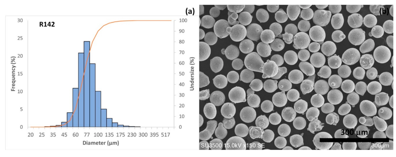
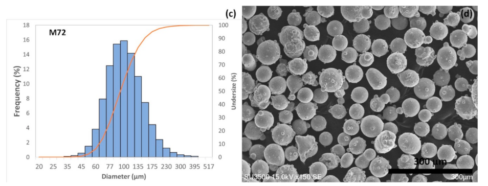
2.1. Powder Preparation and Characterization
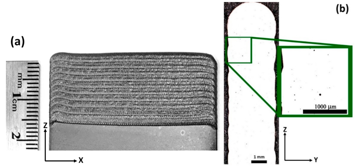
The 4275M72 powder feedstock used in this work was prepared by blending nickel-based R142 (75 wt.%) and cobalt-based M72 (25 wt.%) powders. R142 and M72 powders were blended for eight hours using a V-shaped mixer to produce a homogenized powder mixture. The particle size distribution (PSD) of the powders was analyzed using a Horiba laser particle size analyzer (Model LA-920, Horiba, Kyoto, Japan) and the morphology of powders was observed by scanning electron microscopy (SEM) using a Hitachi SU3500 SEM (Hitachi, Tokyo, Japan). The chemical composition of materials, as provided by the certificate of conformity of the supplier, was established by inductively coupled plasma (ICP) mass spectroscopy in accordance with ASTM E1613 is provided in Table 2.

2.2. LDED Procedure

Fabrication of specimens for tensile and oxidation testing was done using a Liburdi automated laser welding system (LAWS1000, Dundas, ON, Canada) equipped with 1 kW CW fiber Ytterbium IPG Photonic laser. The laser beam and coaxial conical stream of powder particles were focused on the surface of substrates as shown in Figure 1b. The powder mix was fully melted then formed a homogeneous deposited layer upon solidification. The chemical composition of deposited alloy was evaluated using inductively coupled plasma (ICP) mass spectrometry analysis.
The fabrication parameters included a deposition head speed of 1.8 mm/s, a laser beam power of 400 W focused to a spot size of 950 µm, and a powder feed rate of 4 g/min. Figure 1c shows a schematic of the 3 mm thick deposited samples. A bi-directional laser scanning strategy was used to fabricate samples for microstructural analysis, tensile and oxidation testing specimens. The samples were deposited on Haynes 230 (H230) substrate. The depositions were 10 cm in length (X), 2.5 cm in height (Z), and 0.2 cm in width (Y).

2.3. Post-Fabrication Heat Treatment

All deposited samples were subjected to post fabricated heat treatment (PFHT) prescribed for turbine blades manufactured from PWA1484 single-crystal material that comprised primary aging at 1353 K (1080 °C) for four hours, followed by secondary aging at 978 K (705 °C) for 24 h. The samples were quenched by argon flow after each heat treatment.

2.4. Microstructural Analysis

Transverse and longitudinal samples for the metallographic examination were extracted from randomly selected areas of depositions. After polishing, samples for optical microscopy were etched using standard Marble’s reagent. Samples for scanning electron microscopy (SEM) and energy dispersive spectroscopy (EDS) were electrolytically etched in 10% chromic acid. The Light Leica DM ILM optical microscope, KEYENCE VHX-5000, (Keyence, Mississauga, Canada), Canada, digital microscope, Hitachi SU-3500 and SU-8000 (Hitachi, Tokyo, Japan), scanning electron microscopes (SEM) equipped with EDS were used to study defects, microstructure, and distribution of alloying elements in the samples in both as-built and heat-treated conditions. Using the micrographs of optical microscopy, pores were quantitatively analyzed then bulk density was calculated. The quantitative analyses of pores and microstructure were performed according to ASTM E1382 employing image analysis using ImageJ version 1.50i software.
The X-ray diffraction (XRD) study was performed using a Bruker D8 Discover diffractometer (Bruker, Germany) with a Co Kα1 radiation (wavelength, λ = 1.78897 Å) running at 35 kV and 45 mA. The XRD scans were performed on the X-Z planes of the polished surfaces of the samples.

2.5. Mechanical Testing

Vickers microhardness test was performed using a Clark CM-100AT (Sun-tec, Novi, USA) automated microhardness equipment with 500 gf load with a 10 s dwell time.
Subsized samples for tensile and stress rupture tests were manufactured as per ASTM E8. After machining, samples were subjected to a radiographic inspection as per ASTM E1032 to meet the acceptance criteria as part of AWS D17.1/D17.1M:2010 Class A.
Tensile testing of samples at room temperature was conducted as per ASTM E8. Tensile tests were performed using a Tinius Olsen, USA machine equipped with stress–strain records and strain pacer via AMDET QUATTRO software. High-temperature tensile testing was done according to ASTM E21. The stress rupture testing was performed in accordance with ASTM E139. The dwell time at each test temperature was 30 min, and stress was kept constant during the test. Three sets of samples were manufactured, tests were repeated at each temperature using the manufactured samples, then an average value is reported in this manuscript.

2.6. Oxidation Testing

Cyclic oxidation testing of pins of 5 mm in diameter and 25.6 mm in length were manufactured from 4275M72, R80, and R142 welds of 7 × 7 × 60 mm in size. Cyclic oxidation testing of the first group of samples was conducted in still air at 1268 K (995 °C) for 1000 h to simulate service conditions of turbine blades of industrial gas turbine engines (IGT). One cycle duration was 100 h for a total test time of 1000 h (10 cycles). The second group of samples was subjected to cyclic oxidation at 1393 K (1120 °C) to simulate the takeoff condition of an aero turbine engine. The cycle exposed the second group of samples to 1393 K (1120 °C) for 50 min followed by cooling and reheating back to 1393 K (1120 °C) for 10 min. The full testing campaign was 500 h. The weight of each group of samples was measured every 100 h.

3. Results and Discussion

3.1. Powder Characterization

Figure 2 shows the PSD analysis and morphology of R142 and M72 powders used to prepare the 4275M72 powder blend. An average particle size of 76 and 96 µm was measured for R142 and M72 powders, respectively. R142 powder showed a narrow spread of particle size compared to the M72 powder. Detailed quantification of PSD analysis is presented in Table 3. Also, particles of both powders mainly possessed spherical shape with some satellites on the particles. M72 particles had more satellites and particles with irregular shapes compared to the R142 powder.

3.2. Compatibility of 4275M72 with LDED
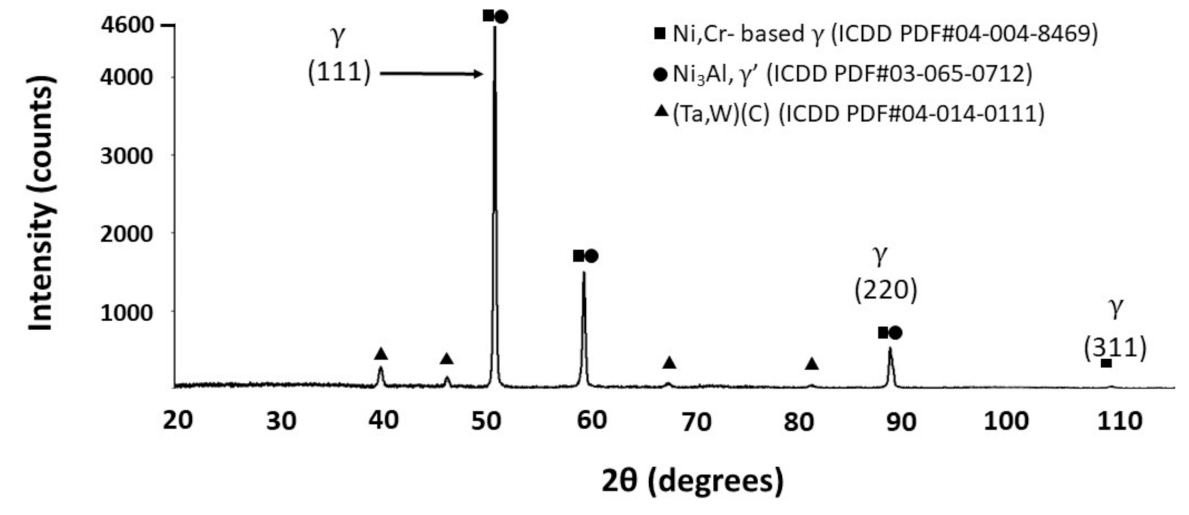
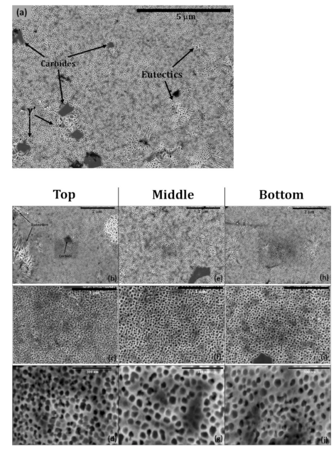
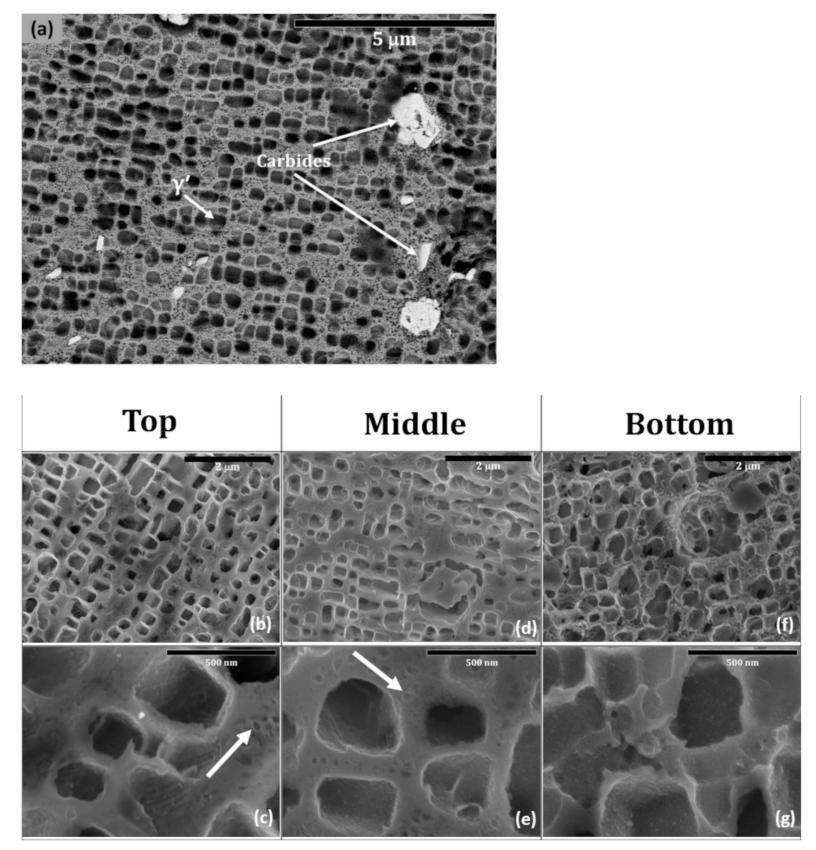
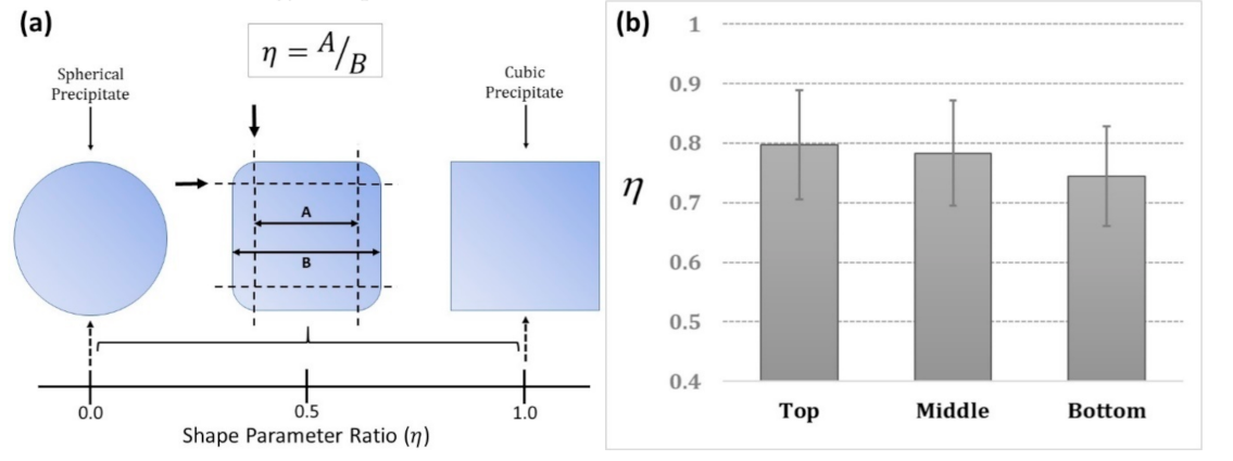
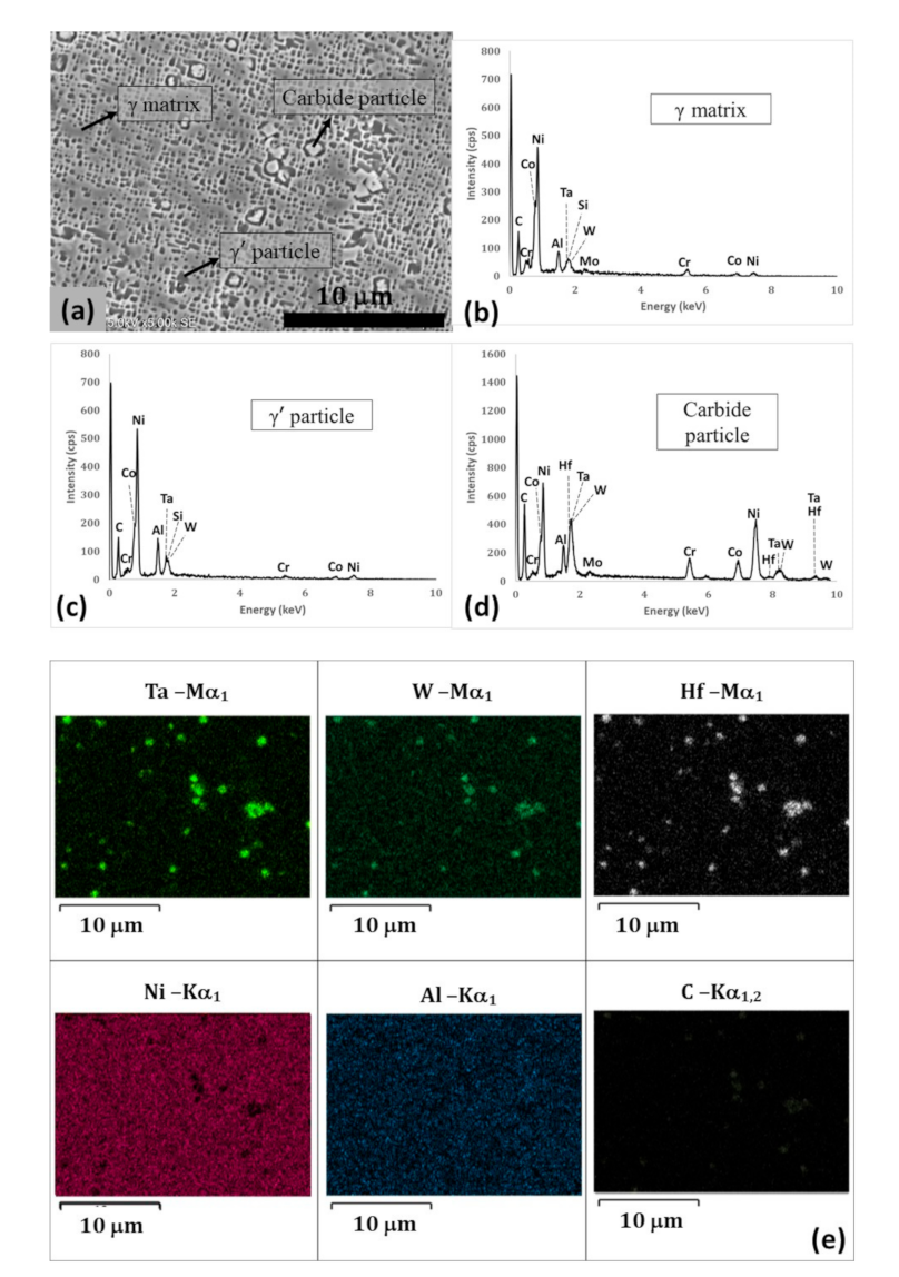
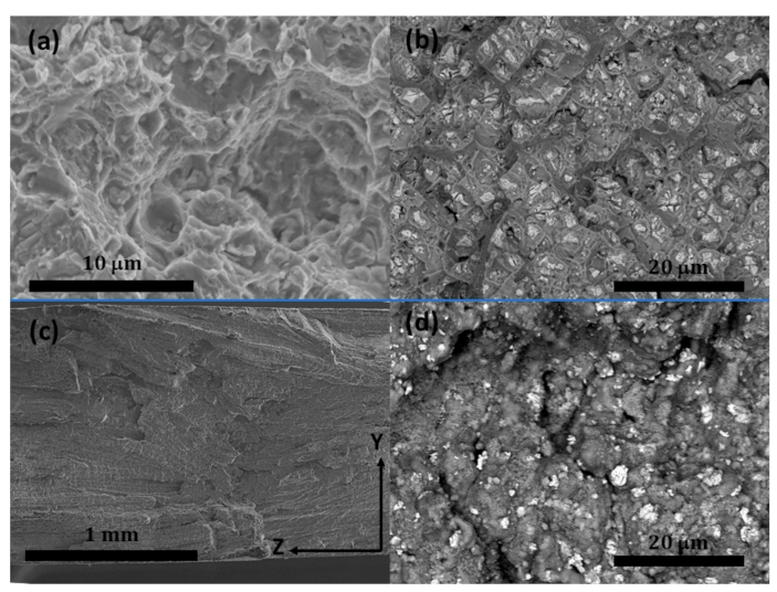
A typical multi-layer 4275M72 LDED built on the H230 substrate in the as-built condition is shown in Figure 3a. Figure 3b shows the polished cross-section of a deposited sample, which was used for image analysis to measure the bulk density of the as-deposited sample. Spherical pores with an average diameter of 65 µm were observed in the builds which were scattered through the build. The smallest pore diameter was around 15 µm and the largest was 135 µm. The average porosity of as-built samples was around 0.8%. Considering the pores as the dominant defects that reduce the density, then the expected density in these parts is 99.2% (±0.1). The micrographs confirmed the accomplishment of crack-free and sound deposition of 4275M72 with the selected LDED parameters.

3.3. Microstructure

The epitaxial grain growth resulted in a formation of a microstructure shown in Figure 4. Generally, in LDED, the formation of columnar grains occurs epitaxially from the substrates and the orientation of the grains is tied to the laser scanning direction [21]. The optical micrograph showed that dendrites grew directionally along the build direction, yet they were contained within the layer and did not grow across the layer interfaces, which resulted in a zigzag fashion grain morphology in the build and the grains had a wide range of intersection angles due to the bi-directional deposition process [22,23,24]. At some interfaces, some grains became fully horizontal, i.e., parallel to the movement of the heat source, which is typical for the solidification of laser depositions [25].
The chemical composition of the 4275M72 samples is presented in Table 4. Also, Figure 5 shows the XRD pattern of deposited 4275M72 after the dual-aging heat treatment. The presence of three phases is evident; a (Ni, Cr, Co)-based phase which denotes the γ matrix of the alloy, an Ni3Al (γ’) precipitate, and a carbide phase of Ta and W (MC type).
Figure 6 shows SEM images of three different sections of the LDED 4275M72 sample in the as-built condition. The as-built samples contained four microstructural features: γ matrix, very fine γ’, γ/γ’ eutectics, and carbide-based particles. The presented phases are in agreement with the XRD analysis. Quantitative analysis of the micrographs, according to ASTM E1382, showed a variation of size and percentage of γ’ in three different sections of the build. The size of γ’ was 39 nm ± 1 in the top section, 64 nm ± 6 in the middle, and 50 nm ± 5 at the bottom part of the build. The volume fraction of γ’ was measured to be around 33% ± 4, 42% ± 3, and 38% ± 2 in the top, middle, and bottom sections, respectively. In the present analysis, the upper deposited layer was not evaluated since this layer is normally removed during the post-fabrication processes. The evaluated top section was around 0.5 mm from the top surface. Cyclic reheating of built layers during multi-pass deposition resulted in precipitation of ultrafine γ’ phase in the as-built condition. The top layers experienced a smaller number of reheating cycles thus the size of precipitates is smaller compared to the rest of the build. The middle section showed the largest precipitates, but at the bottom, although a greater number of reheating cycles was experienced, the size of precipitates was smaller than the middle section. This can be due to the quick sinking of the heat through the substrate adjacent to this section.
Figure 7 shows the microstructure of the build after aging heat treatment. The microstructure of the build after aging consisted of three phases, i.e., γ matrix, γ’ precipitates, and carbide-based particles. When compared with the as-built, the eutectic features were no longer present after the heat treatment, which has been reported in other heat-treated Ni-based superalloys [26]. In general, the microstructure in all three sections of the build after aging seemed more homogenous compared to the as-built sample. These samples showed bimodal size distribution of precipitates including larger secondary γ’ precipitates and very fine tertiary γ’ precipitates. The quantitative analysis of the micrographs showed that the volume fraction of γ’ precipitates after aging was very close to the as-built sample resulted in 37% ± 4, 35% ± 5, 37% ± 4 at the top, middle, and bottom sections, respectively. However, during aging, secondary γ’ precipitates grew and formed larger particles. The average primary γ’ precipitates size was 354 nm ± 41 in the top, 315 nm ± 51 in the middle, and 341 nm ± 23 in the bottom sections. On average, the size of secondary γ’ precipitates in the heat-treated sample was around eight times larger than the γ’ precipitates in the as-built condition. The growth rate of secondary γ’ precipitates under the same heat treatment condition depends on the Al content available in the matrix. More Al was available around smaller γ’ precipitates (in the as-built sample) than that around larger γ’ precipitates. Accordingly, during the aging step, the number of formation elements diffusing into larger γ’ precipitates was less in the areas with larger γ’ [27].
Very fine tertiary γ’ precipitates ranging in size from 20 to 70 nm were observed in the γ-matrix channels as illustrated with arrows in Figure 7c,e. These ultrafine tertiary precipitates represent roughly 3 vol.% of the sample. Generally, the round tertiary γ’ precipitates form during the cooling after solution treatment and aging [28] and similarly to the secondary γ’ precipitates, they contribute to the strengthening.
The shapes of γ’ precipitates can be quantitatively assessed using shape parameter ratio, η, as is graphically shown in Figure 8a. Values of η = 1 and η = 0, represent a cube or sphere shape, respectively [29]. To obtain η in different regions of the cross-section, a minimum of 40 precipitates in each region of the cross-section were analyzed. Where the shape of the precipitate was irregular, two rectangles in two different orientations of each precipitate were drawn, then an average of A and B for the precipitate was taken into account. Figure 8b shows a comparison between η of the top, middle, and bottom sections of the aged sample. The result indicated that all sections possessed secondary γ’ precipitates shaped closer to a cuboidal geometry. Considering the standard deviations of the measurements, there was no significant difference between the shape of the precipitates in different sections. None of the sections possessed a single mode of precipitate shape but large standard deviations of η values show a variation of precipitate shapes in all sections. Changes in the shape of precipitates have been described in the literature as γ’ dissolution behavior in Ni-based superalloys [30,31]. Wang et al. [31] observed precipitates of cubical, cuboidal, and spherical morphology and explained the determination of precipitate morphology due to a competition between the interfacial energy and elastic energy components.
The 4275M72 contains 0.19 wt.% C that drives the formation of carbide precipitates with the refractory elements. Figure 9 shows EDS analysis of the middle section of the build after heat treatment. The carbides were found to be rich mostly in refractory elements (Ta, Hf, and W). These particles were in blocky, cuboidal, and elongated shapes from sub-micrometer up to 3 µm in size.
The heat treatment resulted in a formation of a partially homogenized γ–γ’ structure as shown in Figure 7. However, qualitative EDS analysis showed that the average Al content in γ’ precipitates was 2.5–3 times greater than in γ-matrix.

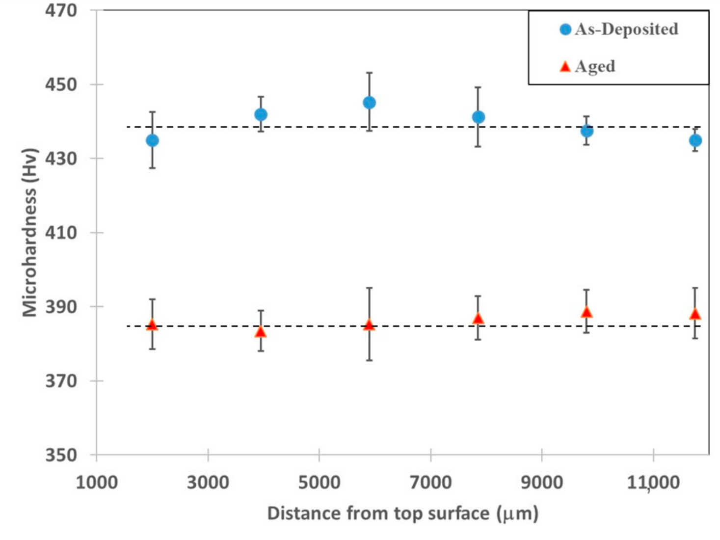
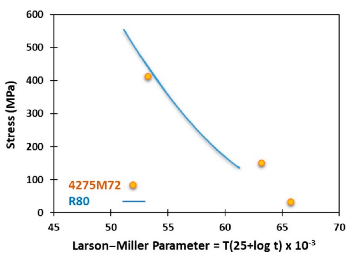
3.4. Mechanical Properties

The microhardness test was performed on the XZ plane of the as-deposited and aged samples. Figure 10 shows the average microhardness values on several lines from top to bottom along the deposition direction. In the as-deposited sample, the hardness values were similar along the build direction although a slight variation in the hardness was observed that can be attributed to the observed variation in the volume fraction and size of precipitates. The contribution of γ’ precipitates to the strength and hardness of the alloy is related to the size, volume fraction, and shape of the precipitates [32,33]. In the as-deposited samples, although the size of precipitates changed along the build direction, the change in the volume fraction of precipitates somehow compensated this size variation and resulted in a more homogenous hardness distribution across the build. In the aged samples, more homogenous average hardness values were observed as it was expected since the size and volume fraction of γ’ precipitates were more homogenous in different areas of the aged sample. However, the average hardness value of the aged sample (385 Hv) was around 13.5% lower than the maximum hardness in the as-deposited sample (445 Hv), which could be related to the formation of the oversaturated solid solution during cooling of welds and differences in the size of γ’ precipitates. As it was shown in the microstructural analysis, the average volume fraction of γ’ precipitates in both as-built and aged sample were very close (around 40%) and the ultrafine tertiary precipitates in the aged samples only possessed around 3 vol.% of the sample, however, the average size of the precipitates after aging was eight times larger than the as-built condition. Finer precipitates of γ’ in the as-deposited sample and potentially higher Al content in the oversaturated solution of gamma matrix can be the main cause of higher hardness in this sample.
Tensile testing was performed on the aged samples since this alloy is a precipitate hardened alloy and practically should be used only after aging post-weld heat treatment. Table 5 shows the tensile properties of LDEDed 4275M72 from room temperature up to 1366 K (1093 °C). The strength of 4275M72 was superior to R80 (see Table 1) in almost the entire test temperature range. At room temperature, the ultimate tensile strength (UTS) and yield strength of 4275M72 were 26% and 22% higher than those of R80, respectively, when it demonstrated 50% higher ductility. However, at elevated temperatures R80 possessed higher ductility compared to 4275M72.
The superior strength of 4275M72 deposits when compared to R80 tensile properties provided in Table 1 can be attributed to higher volume fraction of γ’ precipitates (around 40 vol.% compared to 28 vol.%), Re solid solution strengthening [34], and precipitation of a larger amount of carbides due to higher carbon content. Re can effectively lower the coarsening rate of the γ’ precipitates, which is mostly due to its very slow diffusion rate in nickel. Additionally, the presence of Re in the solid solution is believed to increase the activation energy of dislocation motion in the matrix [35].
Fracture analysis of tensile samples at room temperature showed carbides linked by areas of ductile dimple fracture as shown in Figure 11a,b. These fractographs exhibit ductile fracture characteristics with dimples and decohesion being the main features in these fractured surfaces. The backscattered electron image in Figure 11b showed the presence of brittle carbide particles, which were cracked, within and between the dimples (bright particles). The fracture mode varied with the increasing of the test temperature, resulting in a fracture transformation from 100% dimple transgranular at room temperature to 100% interdendritic decohesion at 1255 K (982 °C). Figure 11c,d shows that quasi-cleavage and decohesion are the main characteristics in fractured surfaces of the samples tested at 1255 K (982 °C). It seems that at this temperature the interdendritic region softened and broke but there was no sign of cracks in the carbides thus the weakened interdendritic provided a crack propagation path, which resulted in dendritic characteristic exhibition in the fractured surface of these samples [36]. This fracture behavior can be attributed to a lower content of aluminum in an interdendritic γ-Ni-Co-Cr-Re-based solid solution of welds that did not undergo homogenization solution heat treatment, which will be studied and discussed in following publications. Also, the high content of Co in this solid solution weakened boundaries at high temperatures resulting in the alternation of a fracture to an interdendritic mode.
The comparison of Larson–Miller plots of R80 and 4275M72 presented in Figure 12 shows that stress rupture properties of LDEDed 4275M72 were superior to R80.

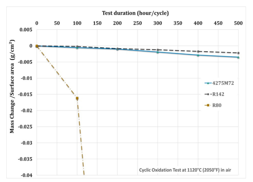
3.5. Oxidation Properties

Figure 13 shows cyclic oxidation resistance test results at 1120 °C (1393 K), a comparison of LDEDed 4275M72 with R142 and R80 welds. Deposited 4275M72 samples demonstrated superior oxidation resistance over standard R80. The oxidation resistance of 4275M72 was very competitive compared to R142, and showed a very similar behavior until 200 h of test duration, and then after this R142 possessed slightly higher resistance compared to 4275M72 up to 500 h of test duration. After 500 h of oxidation test, R142 lost 0.002 g/cm2, 4275M72 lost 0.003 g/cm2 while mass loss of R80 sample exceeded 0.49 g/cm2. A similar trend was observed when the samples were tested at 1269 K (995 °C) for 1000 h. At this temperature 4275M72 lost 0.0006 g/cm2 in 500 h and the loss of R80 was 0.0065 g/cm2, which was not as drastic as at 1393 K (1120 °C).
The 4275M72 deposits inherited high oxidation resistance from R142 and M72, which was attributed to a high content of Al and Cr while low oxidation resistance of R80 at 1393 K (1120 °C) was attributed mostly to a high content of Ti.

4. Conclusions

The quickness and precision of the turbine blade repair process are major advantages of the LDED process compared to the conventional repair techniques. This technique gives the opportunity to the end-users to redesign and repair components without the intervention of any external supplier by using their own experience and knowledge. In the presented work, a 4275M72 powder blend comprising of 75 wt.% of Rene 142 and 25 wt.% of Merl 72 powders demonstrated good weldability and produced sound LDED welds at an ambient temperature which is a major advantage compared to using homogeneous superalloys with a similar chemical composition that are prone to cracking and require preheating to temperatures exceeding 1173 K (900 °C) to produce crack-free welds. The proposed process showed the capability of producing high uniformity without any cracking. The manufacturing freedom as a result of using LDED process can lead to turbine tip repair applications such as squealer tip repair, solid tip cap repair, and even full tip replacement. All these applications have been practiced at Liburdi Turbine Services Inc. with accommodation of the LDED flexibility and material performance presented in the current work.
Mechanical properties of 4275M72 deposits were superior to mechanical properties of Rene 80 welds due to the precipitation of 40 vol.% of gamma prime phase in the ductile Ni-Co-Cr-Re based gamma matrix as well as interdendritic and intergranular W-Ta-Hf-C carbides. Also, oxidation properties of 4275M72 were superior to R80 welds at temperatures up to 1394 K (1120 °C) due to the high content of aluminum in the titanium-free weld metal. Based on a combination of good weldability with sufficient mechanical and oxidation properties LDED with the 4275M72 powder blend can be recommended for a tip repair of turbine blades in lieu of a tip repair with Rene 80 and Rene 142 welding materials. Due to the lower cost of M72 powder compared to R142, the 4275M72 powder blend costs 10–15% less than an R142 powder supply for a repair application.
In future work, the development of an alloy such that its composition will be identical to the overall 4275M72 powder blend composition can be carried out. Also, a more comprehensive high-temperature mechanical testing and creep behavior investigation, as well as studying the adhesion bonding of the deposition and the substrate and its interface will be part of future studies.

Author Contributions

Conceptualization, M.K.K. and A.G.; methodology, M.K.K. and A.G.; formal analysis, M.K.K., A.C., and D.K.; investigation, M.K.K.; resources, P.L.; writing—original draft preparation, M.K.K.; writing—review and editing, A.G., P.L., and M.B.; supervision, M.B.; funding acquisition, M.B. All authors have read and agreed to the published version of the manuscript.

Funding

The authors would like to thank the research support from the Natural Sciences and Engineering Research Council (NSERC) of Canada (NSERC Project Number: CRDPJ 539429-19).

Data Availability Statement

The data presented in this study are available on request from the corresponding author. The data are not publicly available since sharing the data requires industrial partner approval.

Conflicts of Interest

The authors declare no conflict of interest.

References

  1. Pollock, T.M.; Tin, S. Nickel-based superalloys for advanced turbine engines: Chemistry, microstructure and properties. J. Propul. Power 2006, 22, 361–374. [Google Scholar] [CrossRef]
  2. Ross, E.W.; O’hara, K.S. Rene’142- A high strength, oxidation resistant DS turbine. Superalloys 1992, 257–265. [Google Scholar]
  3. Gontcharov, A.; Tian, Y.; Lowden, P.; Tollett, R.; Brochu, M. Advanced Welding Materials and Technologies for Repair of Turbine Engine Components Manufactured of High Gamma Prime Nickel Based Superalloys. In Proceedings of the ASME Turbo Expo 2018: Turbomachinery Technical Conference and Exposition, Oslo, Norway, 11–15 June 2018; American Society of Mechanical Engineers Digital Collection: New York, NY, USA, 2018. [Google Scholar]
  4. Anderson, T.; Dupont, J. Stray grain formation and solidification cracking susceptibility of single crystal Ni-based superalloy CMSX-4. Weld. J. 2011, 90, 27–31. [Google Scholar]
  5. Banerjee, K.; Richards, N.; Chaturvedi, M. Effect of filler alloys on heat-affected zone cracking in preweld heat-treated IN-738 LC gas-tungsten-arc welds. Metall. Mater. Trans. A 2005, 36, 1881–1890. [Google Scholar] [CrossRef]
  6. Keshavarz, M.K.; Gontcharov, A.; Lowden, P.; Brochu, M. A Comparison of Weldability, Structure, and Mechanical Properties of CM64 and Tribaloy T-800 Welds for Hard-Facing of Turbine Blades. J. Manuf. Sci. Eng. 2020, 142, 101004. [Google Scholar] [CrossRef]
  7. Keshavarz, M.K.; Turenne, S.; Bonakdar, A. Solidification behavior of inconel 713LC gas turbine blades during electron beam welding. J. Manuf Process. 2018, 31, 232–239. [Google Scholar] [CrossRef]
  8. Pallos, K. Gas. Turbine Repair Technology; GE Energy Services Technology, GE Power Systems: Atlanta, GA, USA, 2001. [Google Scholar]
  9. Graf, B.; Gumenyuk, A.; Rethmeier, M. Laser metal deposition as repair technology for stainless steel and titanium alloys. Phys. Procedia 2012, 39, 376–381. [Google Scholar] [CrossRef]
  10. Beaman, J.; Bourell, D.L.; Seepersad, C.; Kovar, D. Additive Manufacturing Review: Early Past to Current Practice. J. Manuf. Sci. Eng. 2020, 142, 110812. [Google Scholar] [CrossRef]
  11. Laureijs, R.E.; Roca, J.B.; Narra, S.P.; Montgomery, C.; Beuth, J.L.; Fuchs, E.R. Metal additive manufacturing: Cost competitive beyond low volumes. J. Manuf. Sci. Eng. 2017, 139, 081010. [Google Scholar] [CrossRef]
  12. Mudge, R.P.; Wald, N.R. Laser engineered net shaping advances additive manufacturing and repair. Weld. J. 2007, 86, 44. [Google Scholar]
  13. Saboori, A.; Aversa, A.; Marchese, G.; Biamino, S.; Lombardi, M.; Fino, P. Application of directed energy deposition-based additive manufacturing in repair. Appl. Sci. 2019, 9, 3316. [Google Scholar] [CrossRef] [Green Version]
  14. Gasser, A.; Backes, G.; Kelbassa, I.; Weisheit, A.; Wissenbach, K. Laser Additive Manufacturing: Laser Metal Deposition (LMD) and Selective Laser Melting (SLM) in Turbo-Engine Applications. Laser Tech. J. 2010, 7, 58–63. [Google Scholar] [CrossRef]
  15. Liu, R.; Wang, Z.; Sparks, T.; Liou, F.; Newkirk, J. Aerospace Applications of Laser Additive Manufacturing. In Laser Additive Manufacturing; Elsevier: Amsterdam, The Netherlands, 2017; pp. 351–371. [Google Scholar]
  16. Singamneni, S.; Yifan, L.; Hewitt, A.; Chalk, R.; Thomas, W. Additive manufacturing for the aircraft industry: A review. J. Aeronaut. Aerosp. Eng 2019, 8, 2. [Google Scholar] [CrossRef] [Green Version]
  17. Wilson, J.M.; Piya, C.; Shin, Y.C.; Zhao, F.; Ramani, K. Remanufacturing of turbine blades by laser direct deposition with its energy and environmental impact analysis. J. Clean. Prod. 2014, 80, 170–178. [Google Scholar] [CrossRef]
  18. Bendeich, P.; Alam, N.; Brandt, M.; Carr, D.; Short, K.; Blevins, R.; Curfs, C.; Kirstein, O.; Atkinson, G.; Holden, T. Residual stress measurements in laser clad repaired low pressure turbine blades for the power industry. Mater. Sci. Eng. A 2006, 437, 70–74. [Google Scholar] [CrossRef]
  19. Gontcharov, A.; Tian, Y.; Lowden, P.; Brochu, M. Mechanical properties and structure of laser beam and wide gap brazed joints produced using Mar M247–Amdry DF3 powders. J. Eng. Gas Turbines Power 2019, 141, 041031. [Google Scholar] [CrossRef]
  20. Gontcharov, A.; Liburdi, J.; Lowden, P. High Gamma Prime Nickel Based Superalloy, its Use, and Method of Manufacturing of Turbine Engine Components. Patent EP18214006 2020.
  21. Parimi, L.L.; Ravi, G.; Clark, D.; Attallah, M.M. Microstructural and texture development in direct laser fabricated IN718. Mater. Charact. 2014, 89, 102–111. [Google Scholar] [CrossRef]
  22. Dinda, G.P.; Dasgupta, A.K.; Mazumder, J. Texture control during laser deposition of nickel-based superalloy. Scripta Mater. 2012, 67, 503–506. [Google Scholar] [CrossRef]
  23. Xiao, H.; Li, S.; Xiao, W.; Li, Y.; Cha, L.; Mazumder, J.; Song, L. Effects of laser modes on Nb segregation and Laves phase formation during laser additive manufacturing of nickel-based superalloy. Mater. Lett. 2017, 188, 260–262. [Google Scholar] [CrossRef]
  24. Ma, M.; Wang, Z.; Zeng, X. Effect of energy input on microstructural evolution of direct laser fabricated IN718 alloy. Mater. Charact. 2015, 106, 420–427. [Google Scholar] [CrossRef]
  25. David, S.; Vitek, J. Correlation between solidification parameters and weld microstructures. Int Mater. Rev. 1989, 34, 213–245. [Google Scholar] [CrossRef]
  26. El-Bagoury, N.; Waly, M.; Nofal, A. Effect of various heat treatment conditions on microstructure of cast polycrystalline IN738LC alloy. Mater. Sci. Eng. A 2008, 487, 152–161. [Google Scholar] [CrossRef]
  27. Gao, S.; Hou, J.-S.; Dong, K.-X.; Zhou, L.-Z. Influences of cooling rate after solution treatment on microstructural evolution and mechanical properties of superalloy Rene 80. Acta Metall. Sin. 2017, 30, 261–271. [Google Scholar] [CrossRef] [Green Version]
  28. Locq, D.; Marty, M.; Caron, P. Optimisation of the Mechanical Properties of a New PM Superalloy for Disk Applications; Office National d Etudes et de Recherches Aerospatiales Onera-Publications: Palaiseau, France, tp(4); 2001. [Google Scholar]
  29. MacSleyne, J.; Simmons, J.; De Graef, M. On the use of 2-D moment invariants for the automated classification of particle shapes. Acta Mater. 2008, 56, 427–437. [Google Scholar] [CrossRef]
  30. Balikci, E.; Raman, A. Characteristics of the γ′ precipitates at high temperatures in Ni-base polycrystalline superalloy IN738LC. J. Mater. Sci 2000, 35, 3593–3597. [Google Scholar] [CrossRef]
  31. Wang, T.; Wang, X.; Zhao, Z.; Zhang, Z. Dissolution behaviour of the γ′ precipitates in two kinds of Ni-based superalloys. Mater. High. Temp. 2016, 33, 51–57. [Google Scholar] [CrossRef]
  32. Lapin, J.; Gebura, M.; Bajana, O.; Pelachová, T.; Nazmy, M. Effect of size and volume fraction of cuboidal gamma’precipitates on mechanical properties of single crystal nickel–based superalloy CMSX-4. Kovove Mater. 2009, 47, 129–138. [Google Scholar]
  33. Ali, M.A.; López-Galilea, I.; Gao, S.; Ruttert, B.; Amin, W.; Shchyglo, O.; Hartmaier, A.; Theisen, W.; Steinbach, I. Effect of γ′ precipitate size on hardness and creep properties of Ni-base single crystal superalloys: Experiment and simulation. Materialia 2020, 12, 100692. [Google Scholar] [CrossRef]
  34. Yu, J.; Sun, X.; Jin, T.; Zhao, N.; Guan, H.; Hu, Z. Effect of Re on deformation and slip systems of a Ni base single-crystal superalloy. Mater. Sci. Eng. A 2007, 458, 39–43. [Google Scholar] [CrossRef]
  35. Huang, M.; Zhu, J. An overview of rhenium effect in single-crystal superalloys. Rare Met. 2016, 35, 127–139. [Google Scholar] [CrossRef]
  36. Du, B.; Sheng, L.; Hu, Z.; Cui, C.; Yang, J.; Sun, X. Investigation on the microstructure and tensile behavior of a Ni-based IN792 superalloy. Adv. Mech. Eng. 2018, 10, 1687814017752167. [Google Scholar] [CrossRef] [Green Version]
  37. Klopp, W. Aerospace Structural Metals Handbook; National Technical Information Service: Springfield, VA, USA, 1992; p. 39. [Google Scholar]
Figure 1. (a) Schematic of a typical turbine blade tip with a squealer rim, inset shows cross-section of the tip and hypothetically repaired squealer tip (b) schematic of LDED head with coaxial powder feeding, and (c) schematic of a bi-directionally deposited sample and orientation of extracted tensile specimen in respect to the build direction.
Jmmp 05 00021 g001
Figure 2. PSD analysis and powder morphology of (a,b) R142, and (c,d) M72 powders.
Jmmp 05 00021 g002aJmmp 05 00021 g002b
Figure 3. (a) A multi-layer 4275M72 deposition on an H230 substrate using LDED, and (b) polished cross-section of deposited layers showing pores.
Jmmp 05 00021 g003
Figure 4. Optical micrographs of (a) bi-directionally deposited sample, and (b) higher magnification of the selected area in panel (a).
Jmmp 05 00021 g004
Figure 5. XRD patterns of LDEDed 4275M72 after heat treatment. The PDF numbers of matching phases are shown in parentheses.
Jmmp 05 00021 g005
Figure 6. (a) Typical microstructural features of LDEDed 4275M72 in the as-built condition, and evolution of γ’ precipitates in (bd) 0.5 mm from the top, (eg) 15 mm from the top of the build (middle), and (hj) 2 mm from the substrate interface (bottom).
Jmmp 05 00021 g006
Figure 7. (a) A typical back-scattered electron image of aged 4275M72 deposition, and evolution of γ’ precipitates after aging in (b,c) 1 mm from the top, (d,e) 15 mm from the top of the build (middle), and (f,g) 2 mm from the substrate interface (bottom).
Jmmp 05 00021 g007
Figure 8. (a) Definition of shape parameter ratio (η) to quantitatively evaluate γ’ shapes, and (b) average values of η in three sections of aged 4275M72 LDEDed sample. The error bars represent standard deviations of the values.
Jmmp 05 00021 g008
Figure 9. (a) The 4275M72 deposits produced from the powder blend after PFHT depicting precipitation of γ’ phase and Ta-Hf-W-based carbides in the γ-matrix, (bd) EDS spectra of phases indicated in panel (a), and (e) EDS elemental maps of carbides in panel (a).
Jmmp 05 00021 g009
Figure 10. Vickers microhardness measurement results in as-deposited and aged 4275M72 samples along the build direction from the top layer towards the substrate.
Jmmp 05 00021 g010
Figure 11. Fractographs of tensile testing samples of LDEDed 4275M72 depicting (a) a secondary electron (SE) image and (b) a backscattered (BSE) image of samples tested at room temperature, and (c) SE image and (d) BSE image of the sample tested at 1366.5 K.
Jmmp 05 00021 g011
Figure 12. Larson–Miller plot of 4275M72 compared to R80 [37].
Jmmp 05 00021 g012
Figure 13. Cyclic oxidation resistance of LDEDed 4275M72 compared to R142 and R80 welds at 1120 °C (1393 K).
Jmmp 05 00021 g013
Table 1. Tensile properties of M72, R80, and R142 materials [3].
MaterialTest Temp.
K
UTS,
MPa
YS,
MPa
ε
%
M72 Welds125512910886.8
1366.5815955.8
R142 Cast Rods12554914861.0
1366.52842152.4
R142 SWET Welds1255240-2.7
1366.51391375.3
Rene 80 GTAW Welds29410358178.0
58970355519.4
125538131316.5
1366.52531688.8
Table 2. Chemical composition of materials used in this work in wt.%.
CoCrMoWNbTaAlHfReZrTiBCNi
R142126.81.54.9-6.36.11.22.80.02-0.0150.12Bal.
M72Bal.20-9.0-34.51.0-0.20.45-0.415
R809.51444--3--0.01550.0150.12Bal.
Table 3. PSD analysis of R142 and M72 powders.
D10 (µm)D50 (µm)D90 (µm)
R1425376101
M726396150
Table 4. Chemical composition of deposited 4275M72.
CoCrMoWTaAlHfReZrYBFeCTiNi
20101.05.65.25.71.12.20.0150.110.0110.010.190.12Bal.
Table 5. Tensile properties of LDEDed 4274M72.
MaterialTemp. (K)UTS, (MPa)YS, (MPa)ε, (%)
4275M72
LDEDed
Metal
294130399912.0
5897927203.1
12554634298.8
1366.52161745.0
UTS: ultimate tensile strength, YS: yield strength, δ: elongation.
Publisher’s Note: MDPI stays neutral with regard to jurisdictional claims in published maps and institutional affiliations.

