1. Introduction
Friction stir welding (FSW) is a welding process that has proven its advantages against more traditional methods, such as GMAW (gas inert arc welding) and GTAW (gas tungsten arc welding), for joining aluminum, magnesium light alloys and dissimilar, allowing one to obtain welds without the most common discontinuities, such as microsegregations, materials phase changes and geometry distortion [
1,
2]. The reason for those benefits is related to the process itself; FSW uses a non-consumable tool with specific geometrical characteristics, such as a shoulder, a pin, and some features that aid in retaining and stirring the bulk material while the tool rotates and advances at a constant speed along the welding faces. Because it is a joining method derived from friction processes, the energy input is lower compared with the arc counterparts, without involving any melting, despite the extreme plastic deformation, helping to obtain uniform results and less distortion [
3].
In Colombia, the FSW technique has been studied since the late 2000s, with attempts regarding its implementation using available and traditional machinery and employing simple FSW tooling [
4], followed by subsequent investigations assessing the weldability of 2000, 5000, and 7000 aluminum alloy series, and parameter development [
5,
6,
7,
8]. This was later supported by investigations around the residual stresses and numerical models applied to the tools and welded region [
9,
10,
11]. All of this has led to a solid knowledge around the process from an academic perspective, but the lack of a bridge between industry and academy is reflected in the absence of implementation by engineers and domestic manufacturers.
Since the 1990s, the railway industry has observed great potential in the usage of FSW in the construction of cabins, frames, and other structural components, because it is possible to use aluminum to enhance structural integrity while reducing weight, which translates to lighter wagons, lower energy usage in daily operation, and greater safety. Examples of those accomplishments come from the Shinkansen and Hitachi in Japan [
12,
13], and Hydro Marine and Sapa in Europe [
14] (along with other cases around the world), but it is not locally implemented to manufacture train components.
The railway industry in Colombia, is focused on operation and maintenance, not on new train manufacture. However, the projected refurbishment of trains, specifically some aluminum components used by Metro de Medellín (MdM) [
15], linked with the government inversions in the multimodal transportation grid and future funds and acquisitions, has generated interest in the manufacture of these parts by processes such as FSW, which finally will help to settle a better relationship between local knowledge and further developments, aiming for fewer imports and the greater competitivity of regional industries. All of these require testing in similar machinery, and the evaluating not only of the cost of production, but also the possible geometries to be manufactured.
The component selected for this case study is a “C”-shaped channel, which provides support for the gate mechanism that opens and closes the wagon doors of the MAN trains in use by MdM trains. These were originally manufactured using a tailor-made extrusion die in conjunction with arc-welded parts, which were then machined to the final requirements. Replacement parts are no longer available from the OEM (Original Equipment Manufacturer), and due to the projected number of components to be made in the near future, the reproduction of the original fabrication route is uneconomical using aluminum extrusion.
In this article, the considerations required to implement FSW as a feasible way to fabricate components using conventional machinery, without tilting the FSW tool, are presented along with details regarding design criteria and welding parameters for complete welds, followed by a construction of a prototype made to evaluate the application. This is additionally paired with the usage of a novel tool with a scroll and particular geometrical features around the pin, to guarantee a sound weld without tilting, in order to exemplify the real-world applications of the studies that report possible welds without tilting [
16,
17,
18,
19,
20,
21].
The results show that the process can be performed with adequate joint characteristics and lower distortion, compared to existing working components that were manufactured and repaired with arc welding, and without the requirement of further investments by locals and the successful fulfilment of mechanical requirements.
2. Materials and Methods
The component selected for this study case is presented in
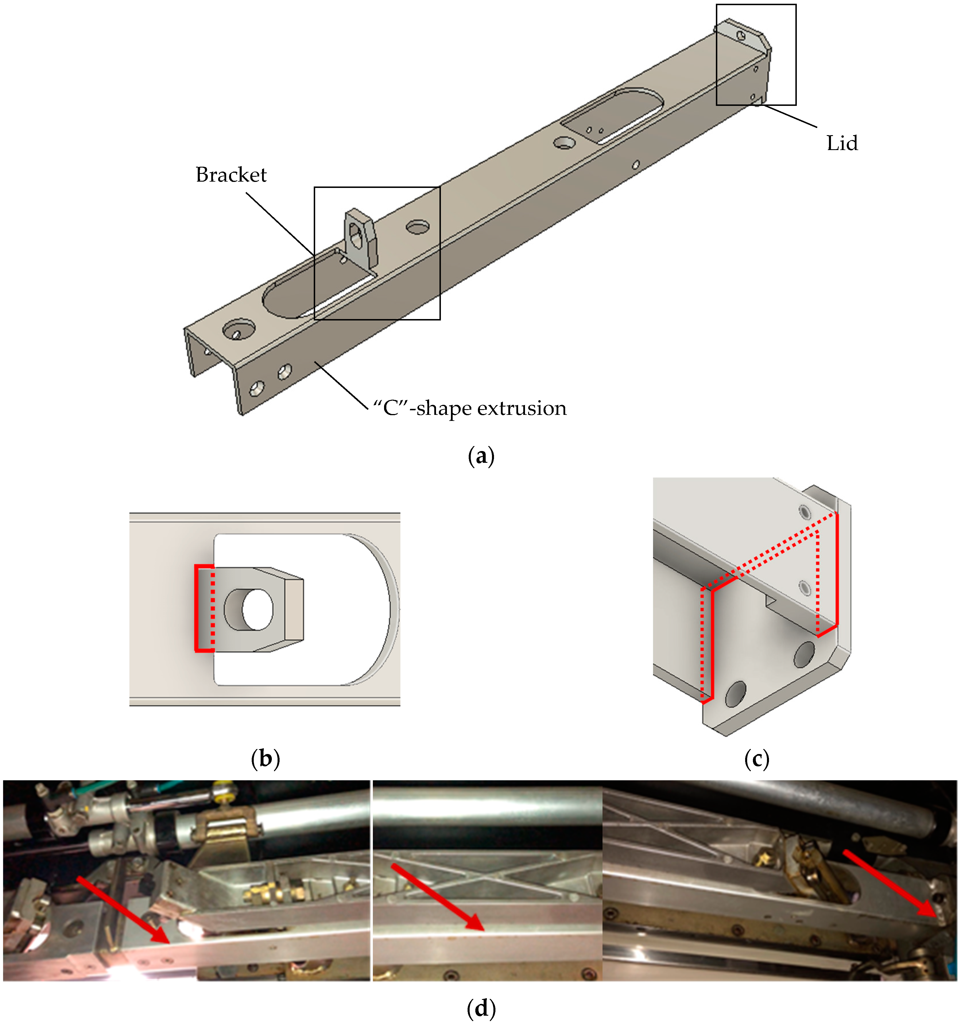
Figure 1. This MAN original part from MdM is an 800 mm long “C”-shaped extrusion, with two welded pieces designated as the bracket and lid (identified in
Figure 1) joined along the edges, represented by the dotted lines, using GMAW welding. The AA6063-T6 aluminum alloy was implemented for the construction of this tailor-made component [
22].
Since no off-the-shelf extrusions could be found that fulfill the C-shaped geometry and thickness requirements, the most suitable manufacturing approach was to reconstruct the component from two L-shaped profiles, thereby minimizing material waste in comparison with the locally used manufacturing approach, i.e., machining from solid bar (
Figure 1a,b).
Two locally available aluminum alloys were considered, with similar or greater yield and ultimate tensile strength compared to the original alloy (214 MPa and 241 MPa, respectively [
23]). These were AA6082-T6 (250 MPa/290 MPa [
24]) and AA7075-T6 (503 MPa/572 MPa [
25]). The base metal selected for this application was a 6.5 mm thickness AA6082-T6, as this is widely available and commonly used in railway applications.
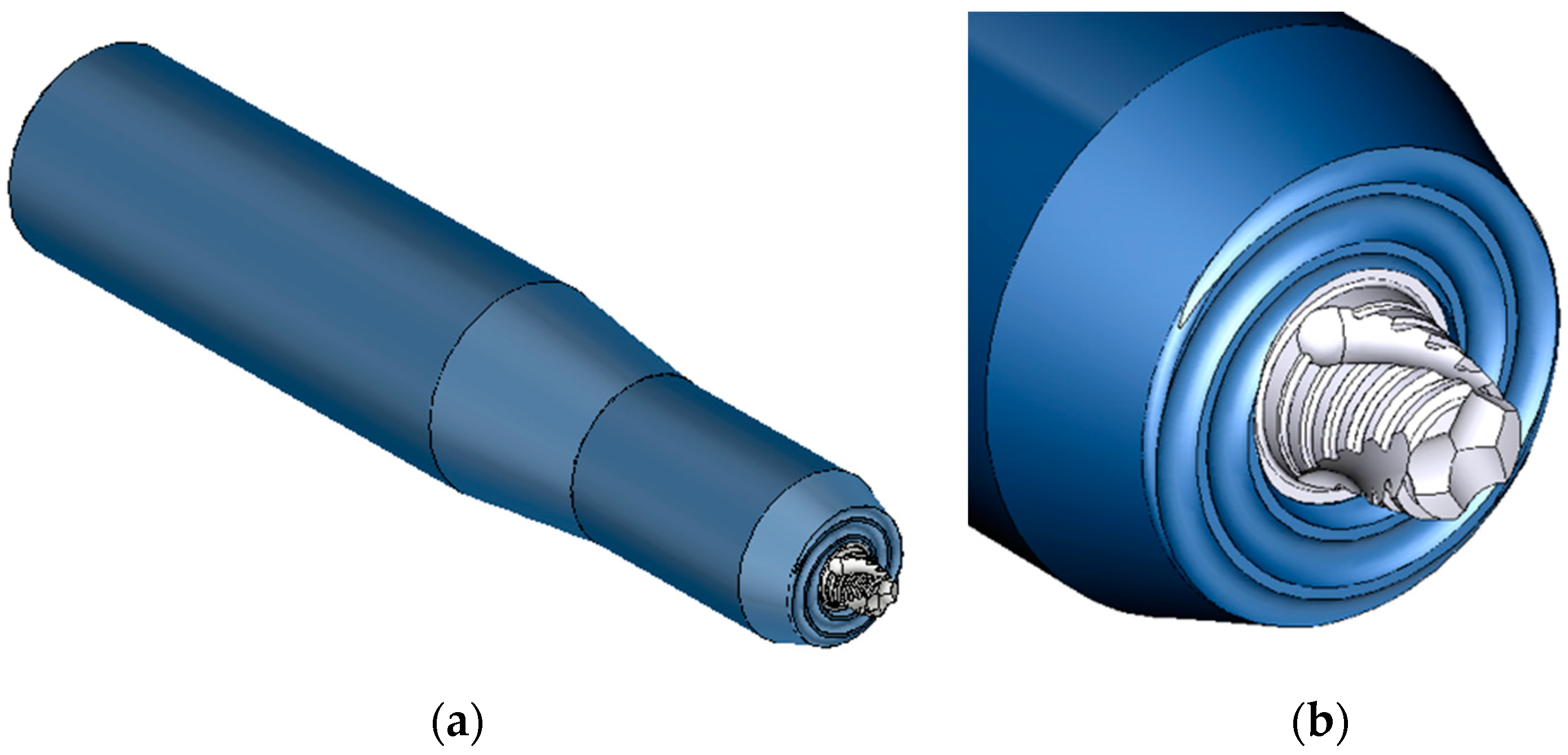
Due to the FSW machine constraints, a tool was designed specifically for operation with zero tilt angle. A heat-treated H13 scrolled shoulder and MP159 threaded probe with tri-flute features was designed and manufactured [
16]. The general tool geometry is shown in
Figure 2; it has a shoulder diameter of 16 mm. The probe length was adjustable to allow for small variations in the material thickness.
Since the original part shown in
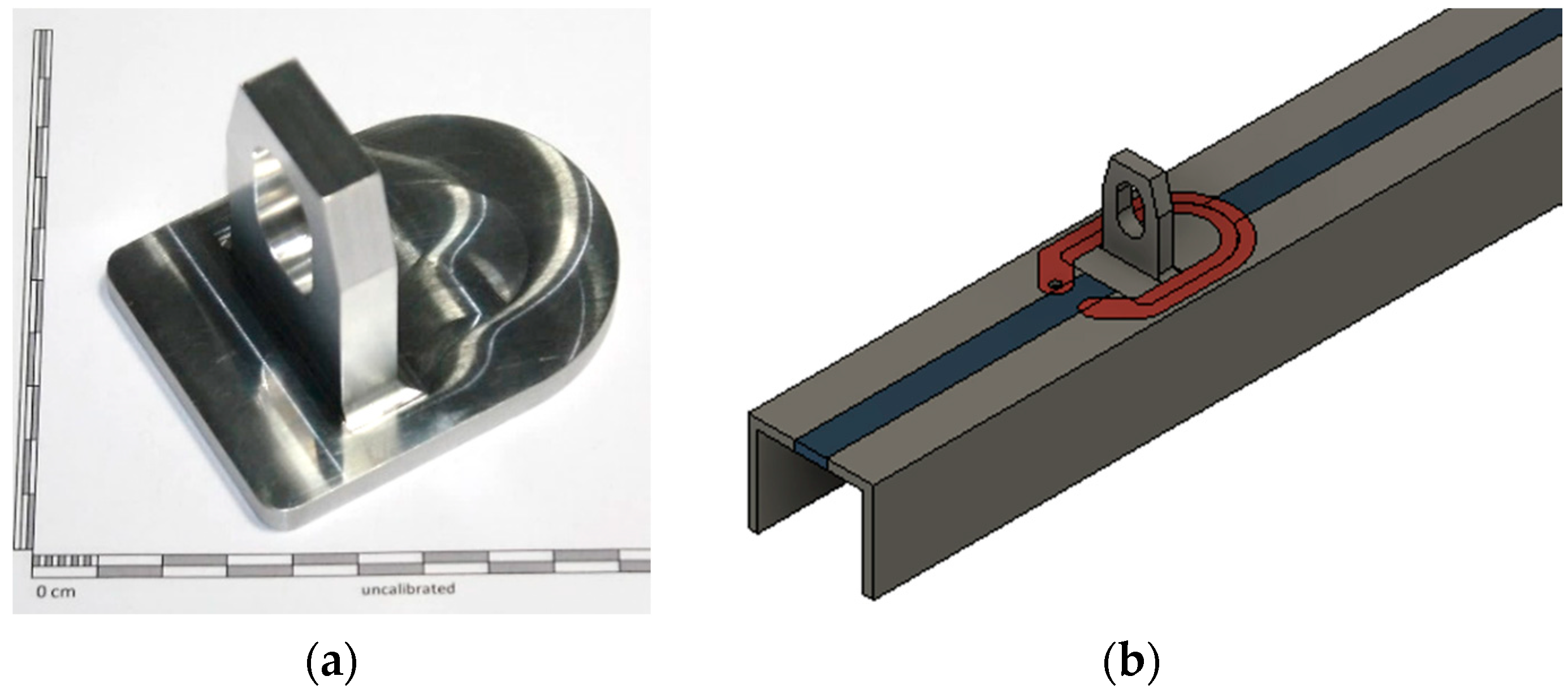
Figure 1 was designed for arc welding, some features had to be re-designed to make them suitable for FSW. The bracket was originally joined to the C-shaped extrusion by a fillet joint, which was not possible by FSW. Instead, the bracket was machined from an AA6082-T6 block (
Figure 3a), and then friction stir-welded in a butt-joint configuration to the C-shaped extrusion using the 2D tool path trajectory (red) shown in
Figure 3b.
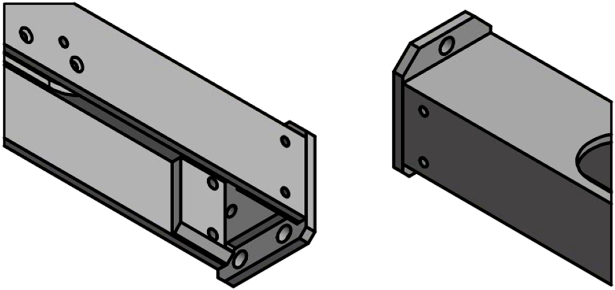
Because the lid presented some difficulties for the implementation of the FSW process, taking into consideration the limitations of manipulating the tool along a non-linear weld path during welding, using the available machinery, a mechanical assembly of the part was proposed, as observable in
Figure 4. This design decision was supported and verified by MdM as the end-user.
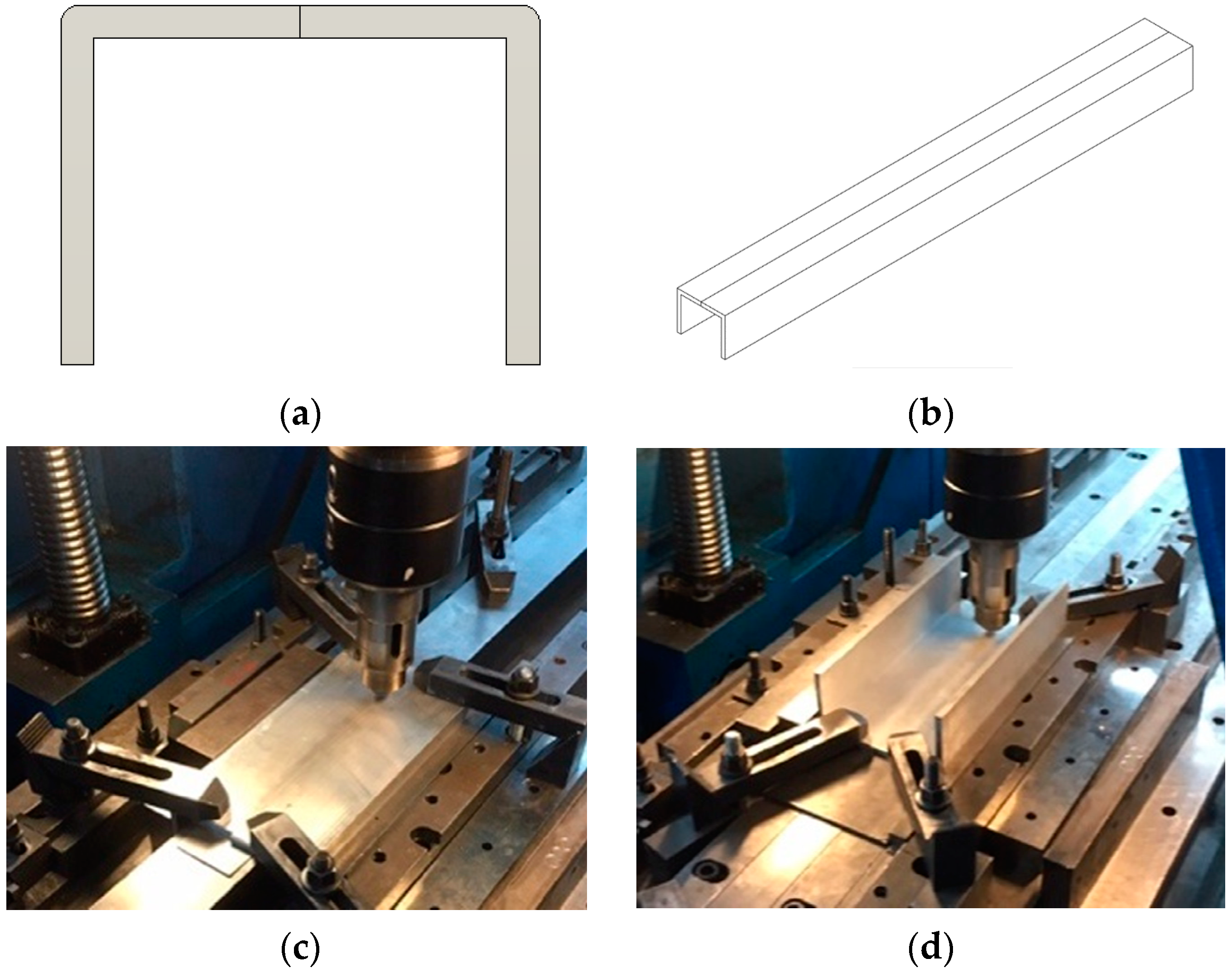
The primary challenge with the longitudinal weld was to reduce fixturing complexity while maintaining FSW tool access in the available machinery. Two different configurations were trialed with the L-profiles in upward and downwards configurations, presented in
Figure 5c,d in a similar manner as that which the Colombian equipment permitted. This helped to evaluate the fixture requirements, tool clearance, visual inspection of the seam, initial setup and proper tool probe penetration configuration.
During the development of the welding procedures, the welding parameters were selected, and the welding forces produced were kept within the capability of the machines available in Columbia.
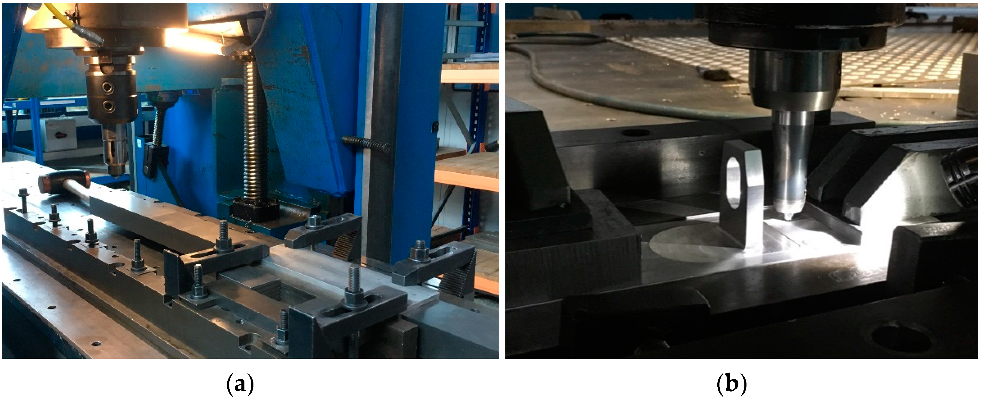
Two specialized FSW machines were used and operated in position control and with a 0° tool tilt angle during the welding operation (
Figure 6), taking into consideration the machines available in Colombia. The welding parameters used were a tool rotation speed of 600 rpm and a welding speed of 600 mm/min for all the welds. This was based on previous experience acquired by TWI (The Welding Institute), when welding this alloy grade and thickness combination.
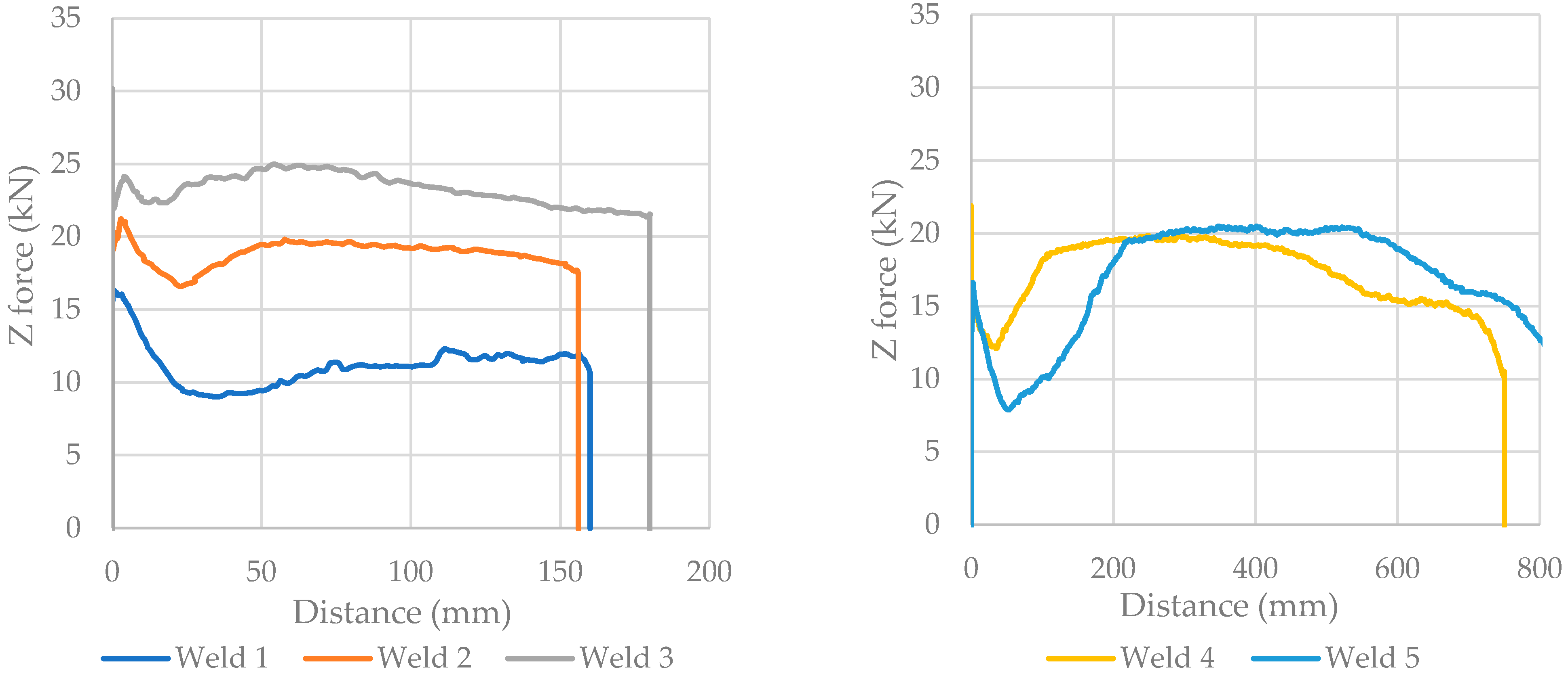
For the data acquisition of the axial force values, 5 different welds were performed, 3 of them with a maximum length of 185 mm and the last 2 were 820 mm long, similar to the final weld length required. All of them were in the downwards configuration. For the bracket seam, 5 paths were established to adjust the tool set-up prior to the prototype weld.
Samples of the longitudinal and bracket welds were transversally cut and polished with emery paper from grits 400 to 3000, followed by micro-diamond polish and Keller etching to evaluate the tool’s penetration and possible discontinuities using the European norm “Friction stir welding—Aluminium (ISO 2523)” as guide [
26,
27,
28,
29,
30]. Microhardness data were acquired using an
Indenter ZHµ machine, set to 300 g and 10 s per sample, locating the horizontal line at 300 μm from the top of the weld to obtain a value comparable with the base metal.
Finally, for the economic evaluation, a comparison between the manufacturing costs and material prices was considered using FSW against the acquisition of pieces by MdM, to provide a baseline cost for local implementation.
3. Results
3.1. C-Shaped Weld
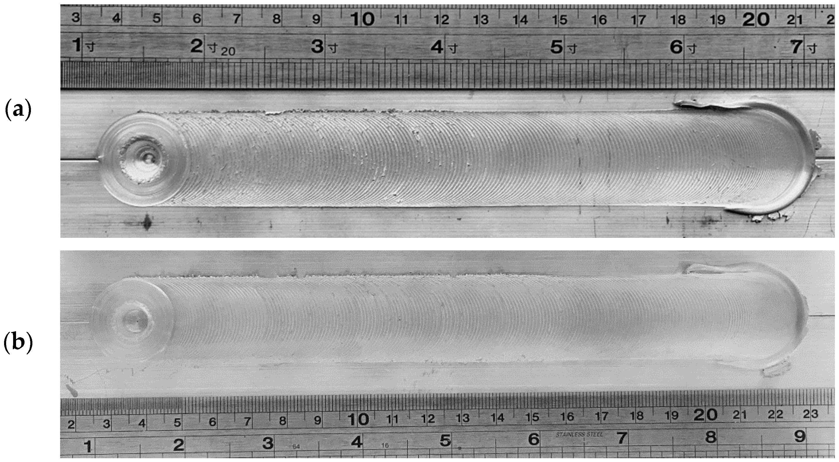
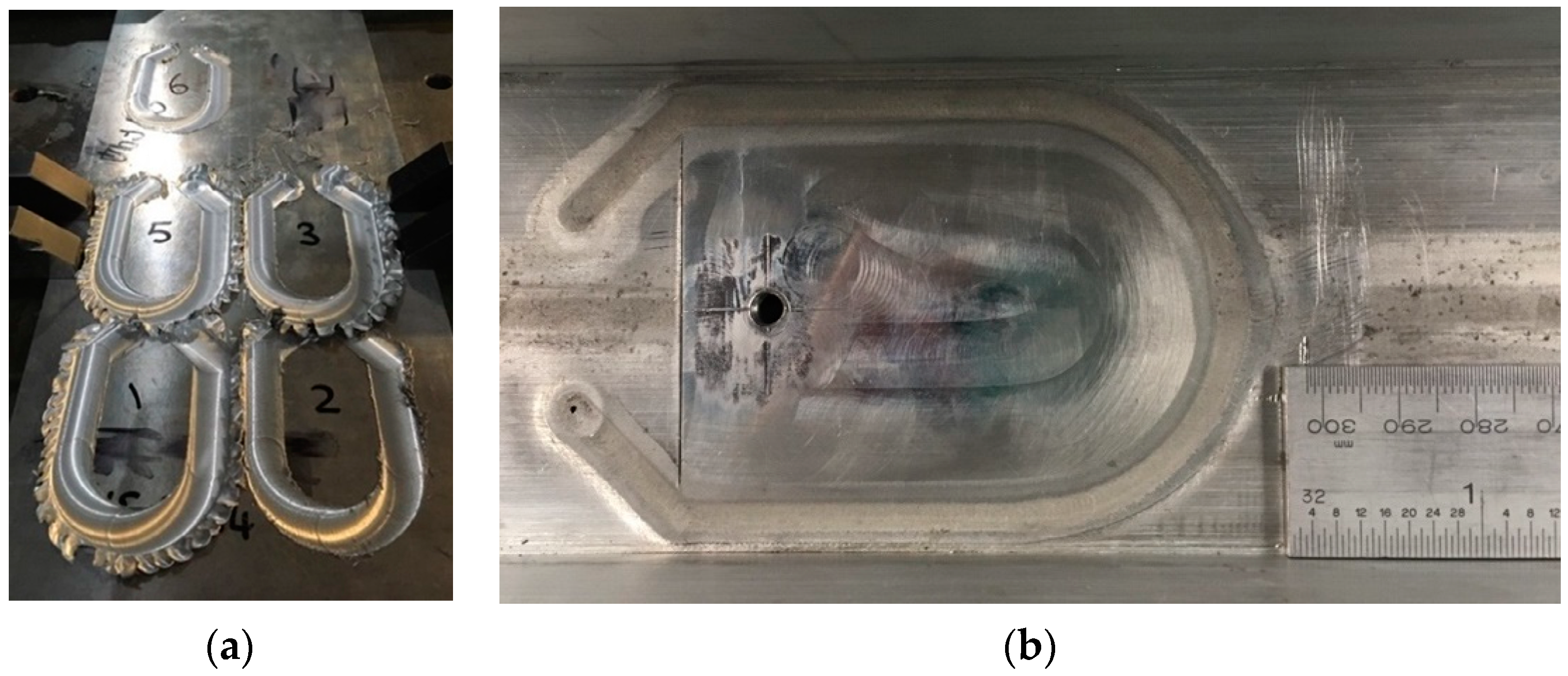
The results for each weld trial configuration (upwards and downwards against the anvil, as shown previously in
Figure 5) are presented in
Figure 7. All the welds had a similar appearance without any visual or significant underfill of the joint due to excessive tool penetration compared with the base metal, meaning that the parameters chosen were correct and in accordance with the quality control and TWI’s experience.
The main difference between these welding configurations relates to how easy it is to fixture the parts. The upward setup presents a more convenient backing plate arrangement which can be a basic flat surface; however, this requires a tighter space for the free movement of the tool to allow collision-free welds inside the C-shape. Furthermore, sufficient clearance is required considering the potential tool deflection on a compliant FSW machine, due to the reaction forces experienced by the machine. Based on this, the downward-facing arrangement was eventually chosen for the demonstrator piece.
The forces recorded in the longitudinal weld trials are presented in
Table 1, which are related to the traverse and axial force. These data help to identify the maximum loading that local equipment has to withstand for this application.
The axial force values presented in
Figure 8 correspond to the five different welds mentioned before, three of which with a maximum length of 185 mm and the last two being 820 mm long (the final weld length), with the same configuration and thickness. These seams follow the typical behavior of FSW welds, highlighting that the maximum force experienced by the machine is due to the initial plunge of the tool in the material for a small period of time, followed by a lower magnitude during the process, on average 10.4 kN, making the selected parameters adequate for local machinery.
3.2. Bracket Weld
In correspondence with the trials described in 3.1, the results for the two-dimensional paths employed are presented in
Figure 9. The main weld flaw obtained was excessive flash, leading to a thickness reduction in the weld region, related to an over-penetration of the tool; as the heat built up in the part, the tool was reset to finally obtain acceptable welds for the application that were in accordance with the ISO 2523 (“Friction stir welding—Aluminum”) [
30].
3.3. Weld Evaluation
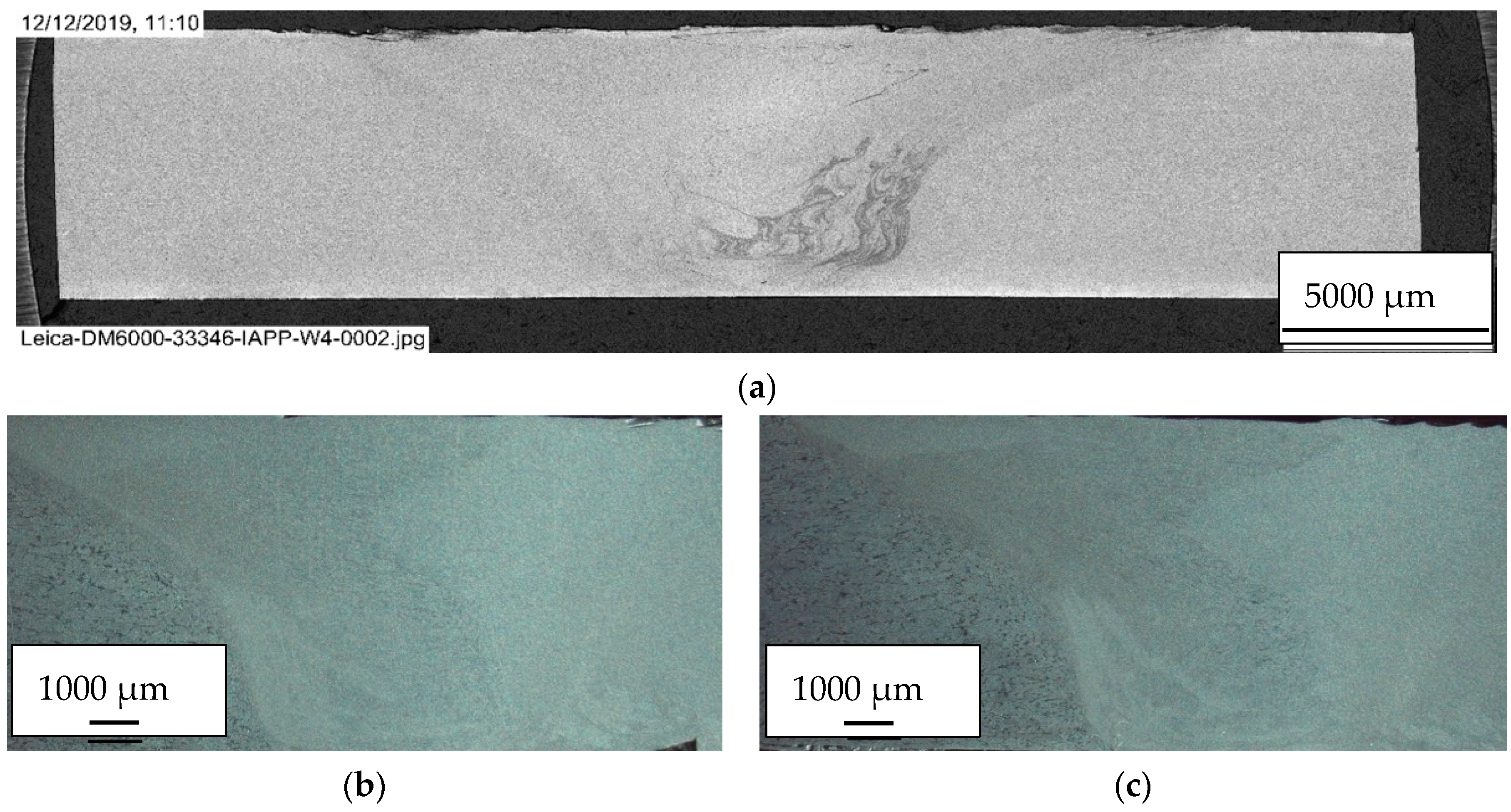
Figure 10 shows the two welds performed; (a) corresponds to the macrograph of the C-shaped longitudinal weld, and (b) and (c) to the bracket on the right and left sides, respectively. Full penetration of the tool is also observable, represented by a stir zone left through the thickness of the material, without any visible void or tunnel defects in the middle of the weld, as expected from a sound weld. Additionally, a superficial roughness on top of the seam is observable, which corresponds to the spirals of the tool (
Figure 3), aligned with the material’s flow, indicating that the geometry does serve as a feature that not only guarantees the containment of the metal, but that also contributes to a stir pattern directed to the pin, helping to obtain satisfactory welding without tilting. Finally, a “lazy-S”-shaped joint line remnant is visible in the nugget zone in correspondence with the material’s agitation left by the pin without a significant underfill.
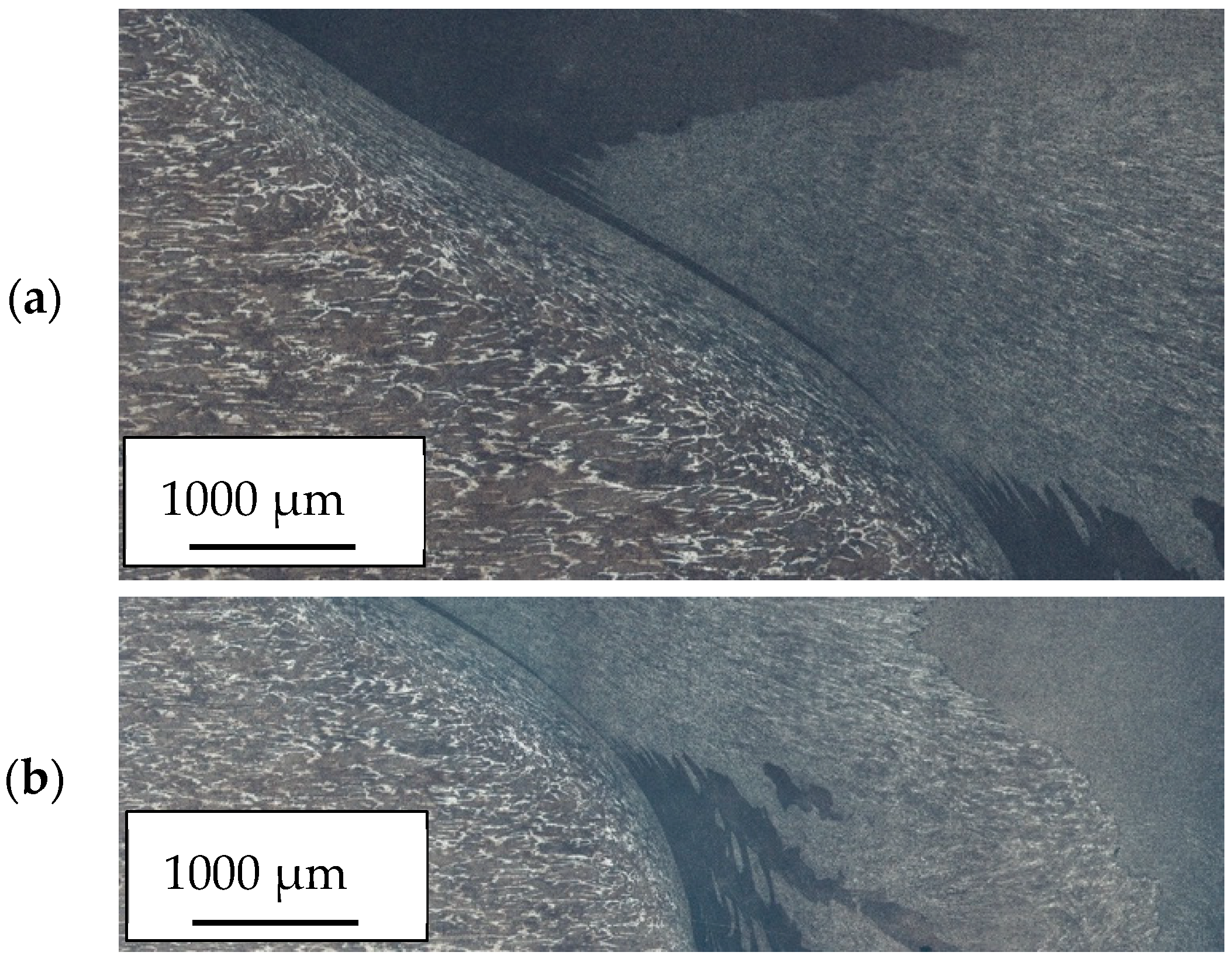
Higher magnification macrographs of the bracket weld around the thermomechanical affected zone (TMAZ) of the right-side show material flow in accordance with the movement of the probe, and the differences between grains due to the dynamic recrystallization tested in FSW (
Figure 11).
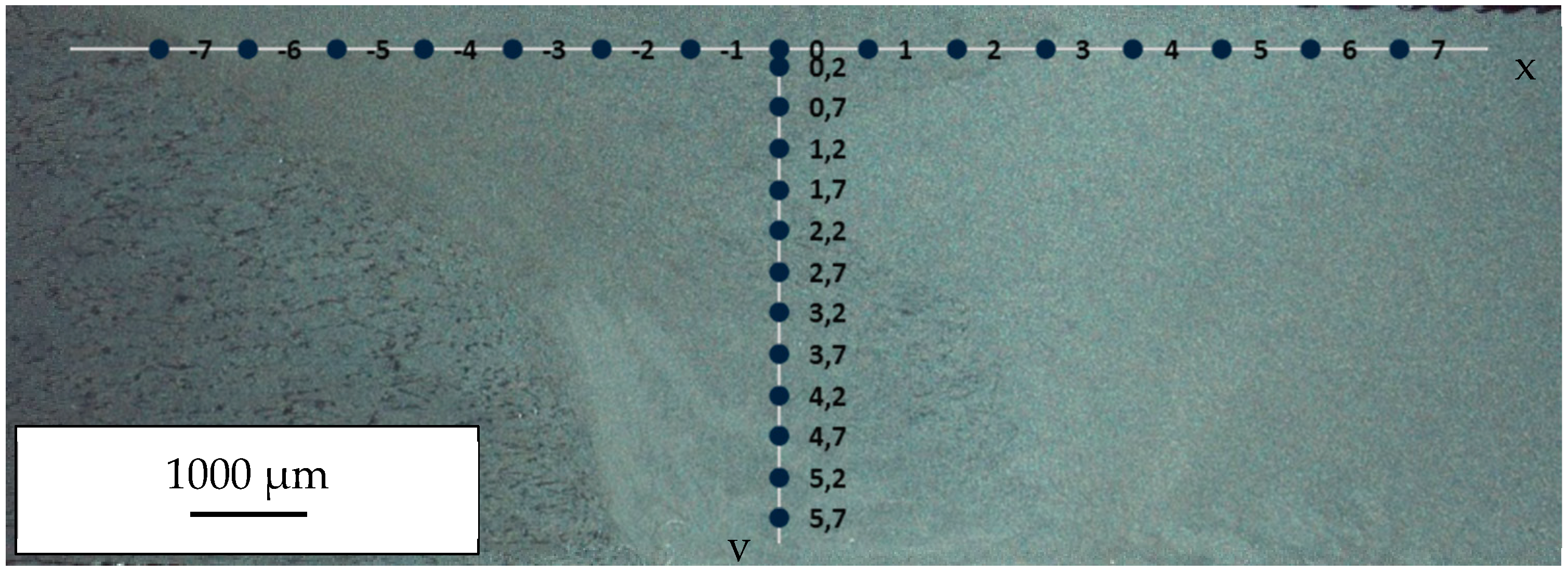
As mentioned before, microhardness data were measured as illustrated in
Figure 12, locating the horizontal line at 300 μm from the top of the weld. The results taken from the bracket weld show values between 65.6 HV and 73.4 HV (on average 69.5 HV), with a standard deviation of 3.9 HV (
Figure 13), a little higher than the average base metal value of 65 HV [
31]. It is observable in both profiles (left and right) that higher hardness values match with the advancing side of the tool, possibly meaning that the special geometry does greatly stir the metal until it is stopped by the retreating side, resulting in the higher recrystallization observable in
Figure 11; in spite of that, the shape is fairly constant, in accordance with other authors, around the 6XXX alloy [
32], but does not present a valley around the weld zone [
33], ascribable to the special geometry of the novel tool, and possibly related with the lesser modifications made to the mechanical properties.
Applying the correlation between hardness and strain proposed by Porter et al. [
34] for aluminum alloys (Equations (1) and (2)), the results show on average
S0.002 = 143.2 MPa and
Su = 233.2 MPa. This gives a 95% proficiency related with the base alloy [
32], which supports the behavior of the hardness and the values obtained around the pin in relation with the geometry of the tool.
3.4. Local Implementation
Locally available data and reported information about the available machinery that could be used for FSW were presented by Jaramillo et al. [
35], and a comprehensive evaluation was made using the force data obtained previously. For the intended purpose, the local equipment was divided between type, capability and industry owner, in order to identify possible local manufacturers to perform FSW (all of these ranging from traditional milling machines to CNC).
Table 2 presents the summary of the locally available machines which can firstly be used for the intended purpose because they can support the average loads during the manufacturing process discussed before, around 10.4 kN; have sufficient space to perform the minimum seam length of 1000 mm required for the construction of the component; are able to use the tooling mentioned for 0° tilting welds, and finally, have the fixing required to adjust to the downward configuration mentioned at the beginning.
It is important to notice that the longitudinal weld can be performed on any of these machines, but the bracket weld requires a CNC capability due to the 2D tool path, in which, for this component, any implementation does require this kind of capability.
Despite the lack of dedicated FSW machines in Colombia, the possibility of using local equipment that can withstand the requirements makes viable the local implementation of this specific component. Further development work is required to transfer this development onto the selected machine for industrial implementation.
3.5. Final Prototype
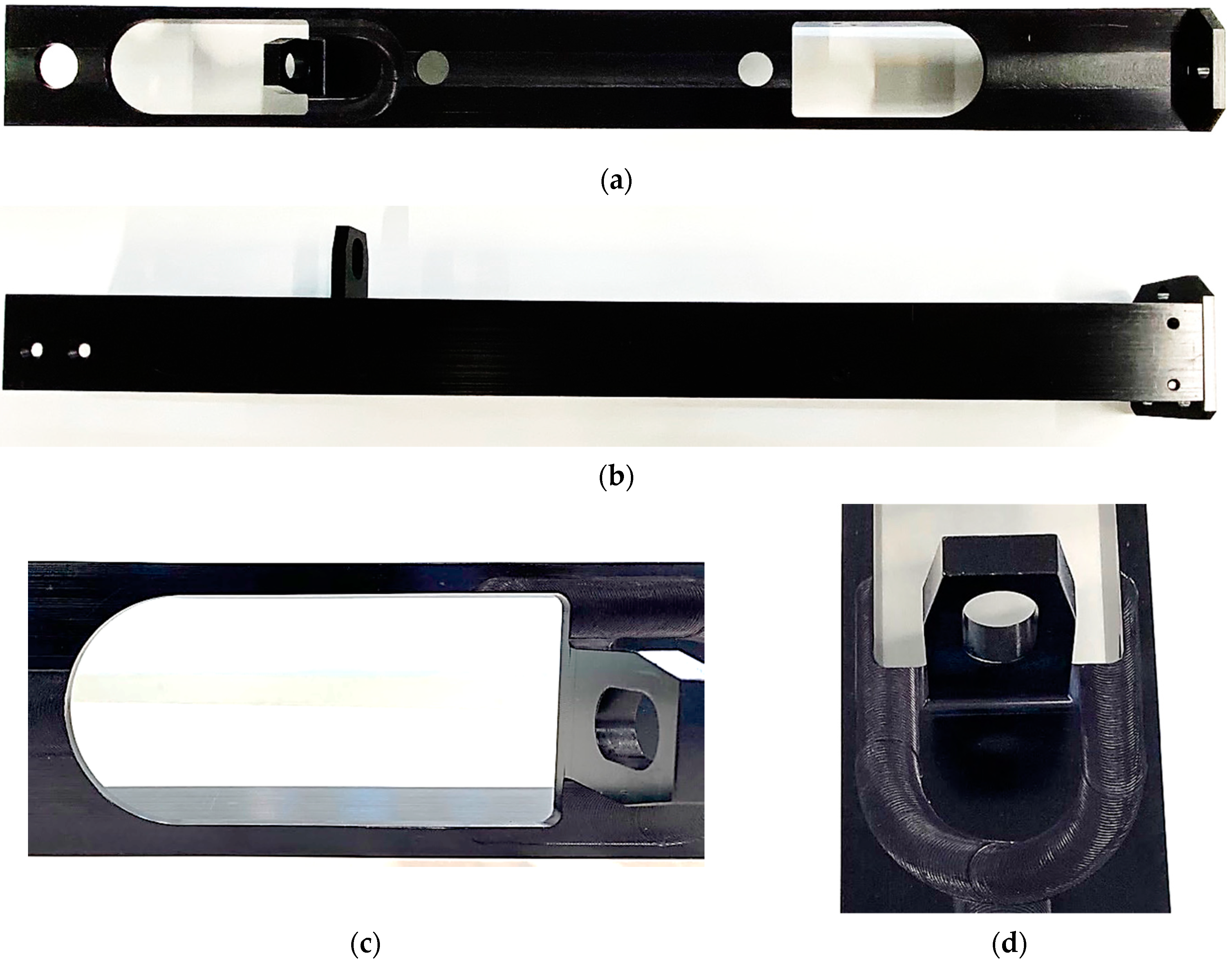
Using the information gathered as mentioned before, the prototype is presented in
Figure 14a,b, the images in which are the top and side views of the C-shaped profile, the bracket and the mechanically attached lid.
Figure 14c,d shows a part of the component, where the longitudinal and the bracket welds intersect. The parameters selected and the initial setup of the tool are adequate to keep the surface quality of the welds, and do not present any excessive flash that could jeopardize the final thickness. Lastly, the FSW process, with a 0° tool tilt, can be successfully implemented to obtain aluminum components that could match the original counterparts without any major problems, and have the alignment and dimensional accuracy needed for the mechanism without any further modifications.
3.6. Economic Evaluation
For the development of this manufacturing strategy by local industries, an economic evaluation of the metal mechanic processes was made to compare FSW against the commercially available replacements previously bought by MdM. The baseline for the analysis is the value of each local manufactured component, around COP 3,200,000 (approximate USD 842), and in
Table 3 the approximate cost of purchasing the materials needed to perform the welds and labor is presented in conjunction with the typical lead time to obtain the material or service, leading to an approximate total value of COP 1,947,000 (about USD 516); 39% less than the locally manufactured product.
Additionally, the tools and anvil used increase the overall price of the component because they are needed to perform the welds but are reusable, lowering the gap from 39% to nearly 30%, depending the estimated volume of components.
This leads to the feasibility of the implementation due to the lower manufacturing price and the possibility of using available machinery, as mentioned before.
4. Conclusions
FSW is a welding process with advantages in comparison with traditional arc methods, making it suitable for its implementation on aluminum alloy components in different applications, such as in railway components.
Through surveys, the requirements of local manufacturers in Colombia were captured, including machine specifications, the availability of alloys, extrusion designs, etc. These requirements were then used for the development of a demonstrator part, a railway door actuator part, to be produced locally. Through process parameter development, tool design, tool materials, component geometry and materials, and re-designs of geometric features of the component involved, the implementation of the FSW process was proven to be viable for local production of the actuator replacement part, using existing local machinery.
The weld performance was assessed in accordance with “Friction stir welding—Aluminium (ISO 25239)”. It was found that the use of FSW tools with a scrolled shoulder, specifically designed for zero-tilt operation and the selection of appropriate weld parameters, enabled the production of void-free welds without tilting. This finding was supported by the literature [
16,
17,
18,
19,
20,
21]. The zero-tilt approach enables future local usage of the welding process on inexpensive, one- or two-axis machinery. The welds were sensitive to variations in tool penetration, requiring particular attention from the operator during setup to avoid lack of penetration.
The economic evaluation leads to a feasible implementation of FSW, and a reduction in the manufacturing cost in the order of 30%.
The information gathered supports the great opportunity for locals to implement the advantages in FSW. Further development is needed to spread awareness of the advantages, and for future developments aiming for Colombian engineering progress.
