Article

Numerical and Experimental Study of AlSi Coating Effect on Nugget Size Growth in Resistance Spot Welding of Hot-Stamped Boron Steels

1
School of Mechanical Engineering, University of Tehran, North Kargar at Jalal-Exp Way, Tehran 1439957131, Iran
2
Department of Mechanical Engineering, Technical University of Denmark, Produktionstorvet 425, 2800 Kgs. Lyngby, Denmark
*
Author to whom correspondence should be addressed.
J. Manuf. Mater. Process. 2021, 5(1), 10; https://doi.org/10.3390/jmmp5010010
Submission received: 26 December 2020 / Revised: 11 January 2021 / Accepted: 13 January 2021 / Published: 15 January 2021
(This article belongs to the Special Issue Metal Forming and Joining)

Abstract

:
In recent years, increasing automotive safety by improving crashworthiness has been a focal point in the automotive industry, employing high-strength steel such as press hardenable steel (PHS). In addition to the improved strength of individual parts in the body of the vehicle, the strength of the resistance-spot-welded joints of these parts is highly important to obtain a safe structure. In general, dimensions of weld nuggets are regarded as one of the criteria for the quality of spot-welded joints. In the presented research, a three-dimensional axisymmetric finite element model is developed to predict the nugget formation in resistance spot welding (RSW) of two types of PHS: the uncoated and AlSi-coated 1.8 mm boron steel after hot stamping. A fully coupled electro-thermo-mechanical analysis was conducted using the commercial software package Abaqus. The FE predicted weld nugget development is compared with experimental results. The computed weld nugget sizes show good agreement with experimental values.

1. Introduction

Resistance spot welding (RSW) is one of the most widely used methods for joining multiple parts in many industrial production lines such as the automotive industry, aerospace industry, and home appliances [1,2]. Increasing automotive safety for improving their crashworthiness while reducing vehicle weight to decrease their fuel consumption and air pollution has been a focal point of attention in recent years. To this end, a wide range of high-strength steels have been employed [3,4]. Press hardenable steels (PHS), which are formed through hot stamping, are considered as one of the most applicable high-strength steels in the automotive industry. During the hot stamping process, the blank is first heated in an approximate temperature of 910 °C for 6 min to become austenitized. Next, the austenitized blank is formed and quenched simultaneously. This process creates a martensitic microstructure in the part, and as a result, improves its strength up to approximately 1500 MPa [5]. In addition to improving the strength of individual parts in the body of the vehicle, the strength of the resistance-spot-welded joints of these parts is highly important [6]. Currently, in the majority of industries, dimensions of weld nuggets are considered as one of the most important parameters in determining the quality of the weld. Many sources emphasize the correlation between the weld nugget dimensions and the load-carrying capacity of the welded joint [7].
RSW is based on generating heat at the interface of two metal parts by applying an electrical current through their joint, which permits the metal to melt and form the weld. In general, there is a direct relationship between heat generation and nugget size in RSW. According to the electrical heat generation equation, the magnitude of heat is proportional to the electrical resistance at the interface of two parts and of course the welding time and the square of the current. Therefore, because of the influence of the contact resistance, the surface conditions such as the presence or absence of coating affects the RSW parameters [8]. Since the parts have to be heated up to 910 °C in the austenitizion phase of the hot stamping, different coatings including AlSi have been used to prevent oxidation on the surface of these parts [5]. Although coating will protect the PHS against surface oxide scale formation during the hot stamping process, the coating will affect the weldability of this kind of steel. From studies comparing the effects of coating on resistance spot welding of steels, it was found that because of the differences between the electrical resistivity and melting point of the coated layer and the substrate, the coating significantly affected the appropriate welding parameters for attaining an acceptable joint [9].
Nowadays, application of PHS in car bodies is very widespread, but there is limited information concerning spot weldability of these steels. Hence, investigating RSW behavior of this material is of importance.
In order to improve the quality of welded joints, many studies have been carried out on RSW by experimental and numerical methods [10,11,12,13]. Experimental tests for studying on nugget growth during RSW have limitations and require expensive equipment. Using numerical simulation can be an appropriate tool to reduce the expenses of experimental costs.
In recent years, some researchers have already studied the modeling of the RSW process and the effect of parameters on nugget formation. Gould [10] measured the dimensions of weld nuggets by using metallographic examination and created a one-dimensional thermal model based on the finite difference method. There were some differences between the experimental and computational results, which were due to underestimation of the heat generation at the faying surface. Tsai et al. used a two-dimensional symmetric model to predict the effect of welding parameters on nugget development. This model was created in the commercial FEM program, ANSYS [11,12]. Nied presented a coupled electrical-thermal-structural axisymmetric model. By using this model, the stress distributions and the displacements of the electrode and workpiece during welding were studied [14]. Cho et al. proposed a finite-difference-based model to predict the temperature and voltage distributions during nugget formation [15]. Eisazadeh et al. introduced a finite element model for parametric study of nugget size during RSW. They verified their results by comparing with published experimental data. The objective of this research was to investigate the effect of electrode force on nugget growth. They observed that by increasing electrode force, nugget dimensions decreased due to reducing electrical contact resistance [16]. Moshayedi et al. investigated on nugget size growth in resistance spot welding of an austenitic stainless steel by experimental and numerical studies. They developed a two-dimensional axisymmetric finite element model to study the effects of welding parameters on nugget formation by using ANSYS commercial software package. According to the results, the dimensions of computed weld nuggets agree well with experimental measurements [17]. Another commercial software, SORPAS®, has been specialized in resistance welding; see, e.g., [18] for the theoretical developments and [19] for application of the software to analyze electrode misalignment in spot welding.
Over the last decade, some studies have been conducted to investigate the effects of coating on resistance spot welding of PHS. Cheon et al. reported that in the case of RSW of Zn-coated PHS, expulsion happened at low current because of fast heat generation at the faying interface [20]. Ji et al. studied the effects of two types of metallic coating such as AlSi and Zn coating on nugget geometry of hot-stamped boron steel subjected to RSW. They found that in the presence of AlSi coating the acceptable welding current was wide enough, while no suitable weld current was found for Zn coating [21]. Ighodaro et al. compared the effects of galvannealed and AlSi coatings on weldability of hot-stamped steels. They expressed that the coating influences the appropriate welding current because of different electrical resistance arising from the different coatings [22].
In this study, a three-dimensional axisymmetric finite element model has been developed to investigate the distribution of temperature and nugget formation of spot weld by using the commercial software package Abaqus. A coupled electro-thermo-mechanical model was set up to study the effects of welding parameters such as applied current and welding time on the nugget size in resistance spot welding of one type of PHS in both AlSi-coated and uncoated forms.
In order to verify the FEM model, various samples of spot welds on coated and uncoated steels in different combinations of current and time were prepared; then, their weld nuggets were measured by an optical microscope after metallography. It is necessary to point out that employing a metallographic cross-section tends to underestimate the actual nugget size and omits ovality effects. The results of finite element analyses were compared with the experimental measurements to verify the model. According to the results, the existing AlSi coating has a significant effect on choosing acceptable welding parameters. The computational results were in good agreement with experimental studies. These findings can yield useful information on the profit and costs resulting from the selection of coated or uncoated steels in the hot stamping process. These results can also be used to optimize the RSW parameters for these materials and coatings.

2. Materials and Methods

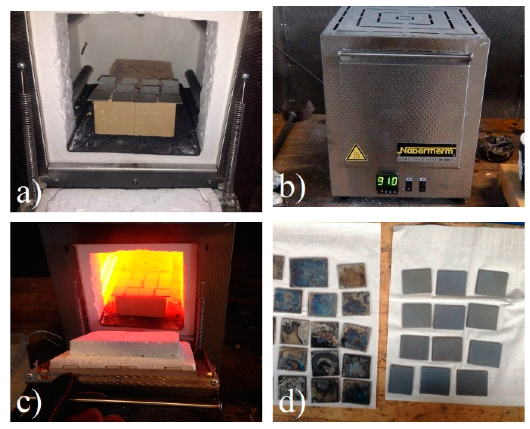
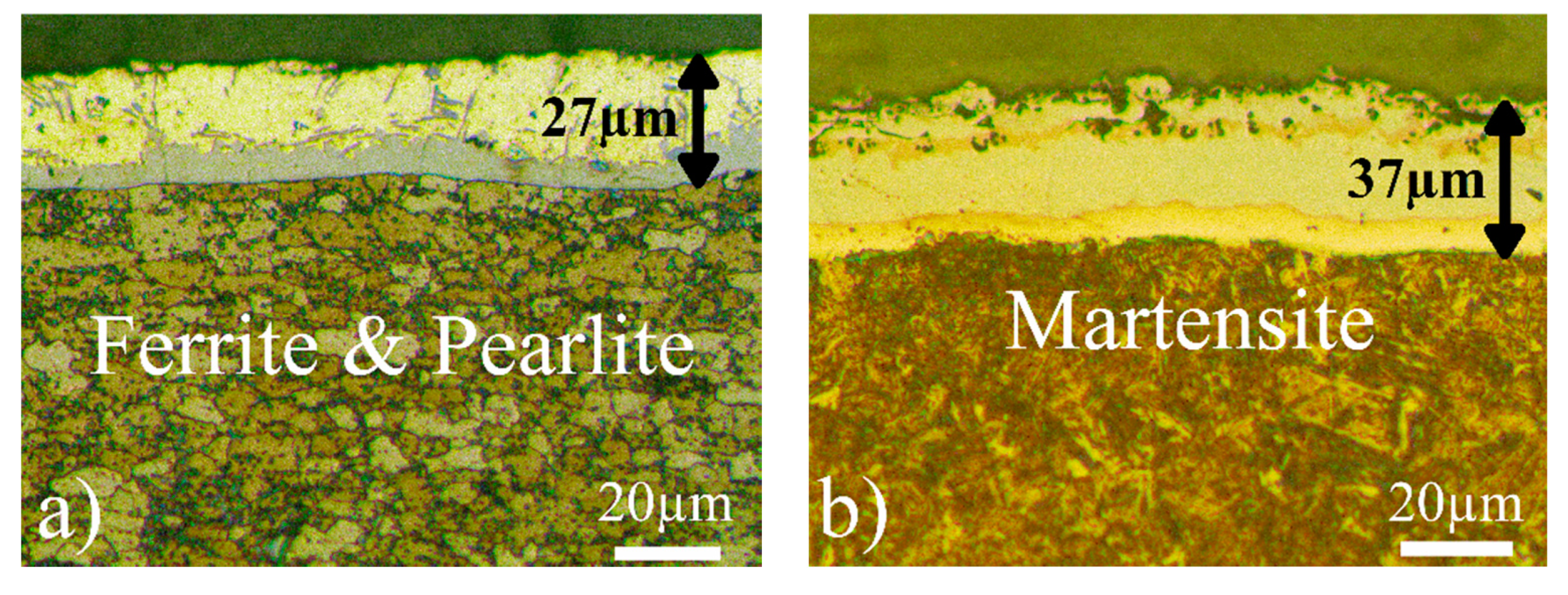
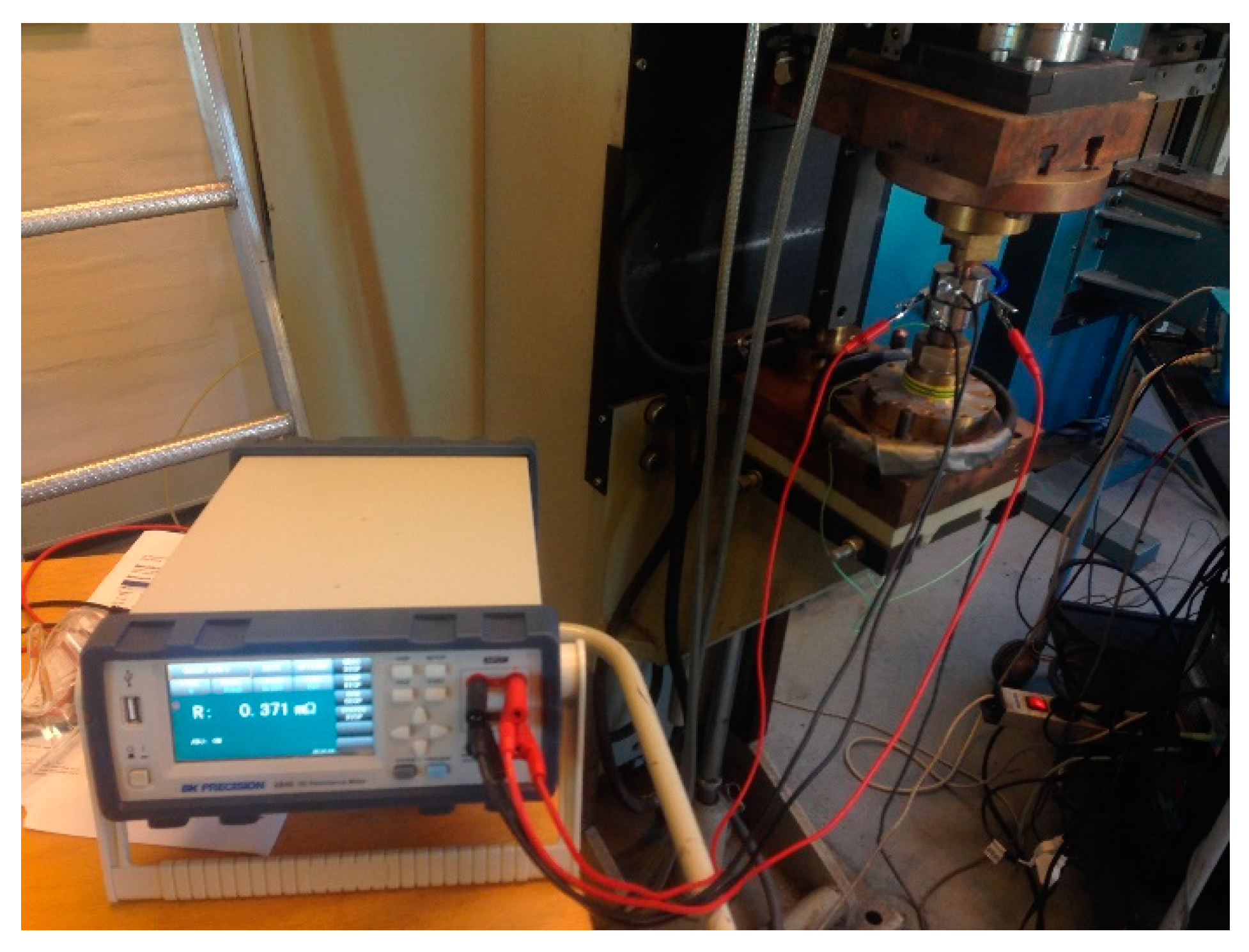
2.1. Experimental Work
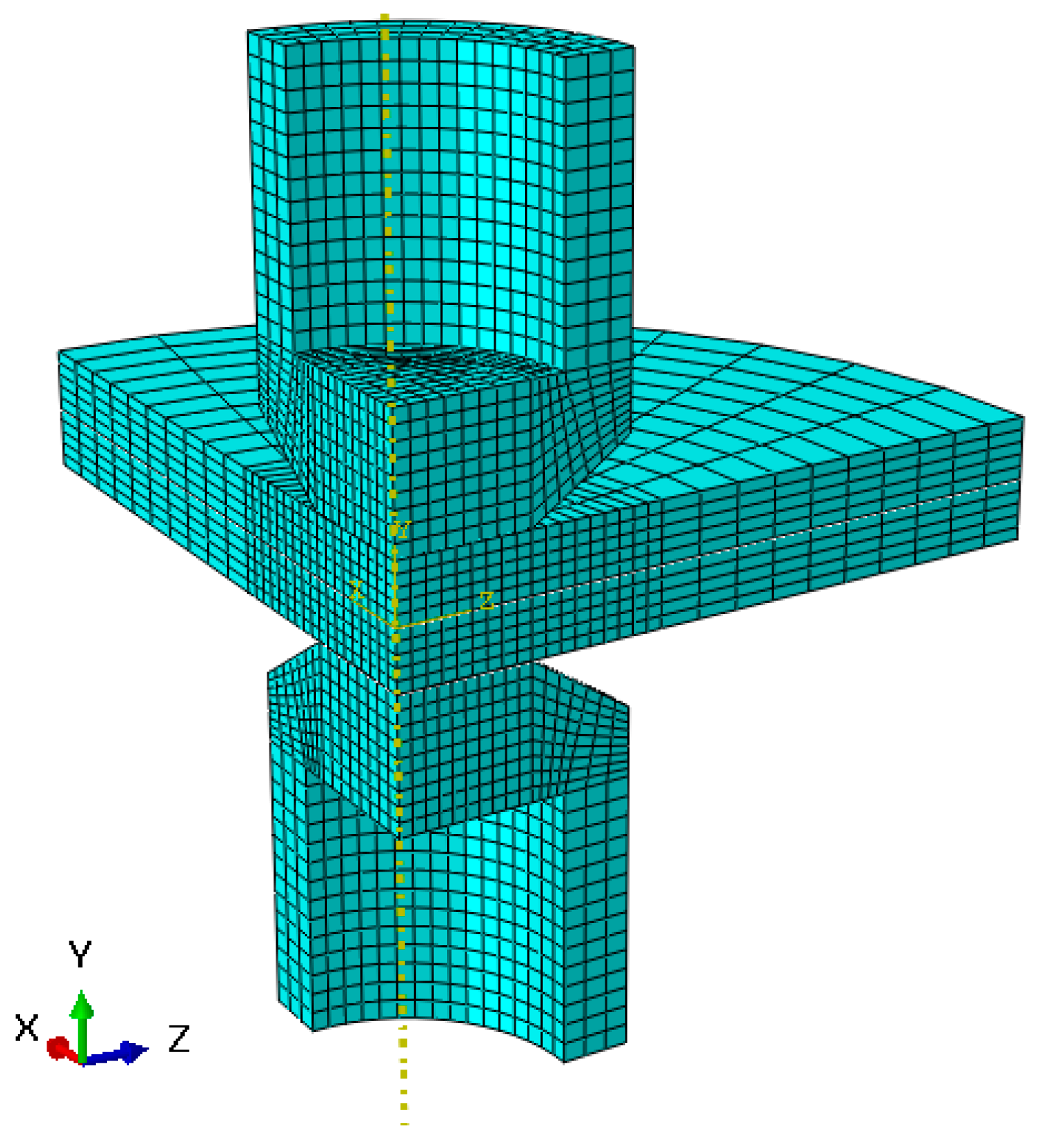
The materials used in this study were Usibor 1500 boron steel in uncoated and AlSi-coated forms. The thickness was 1.8 mm in both cases. The chemical composition of these two steel sheets is reported in Table 1. The steels were cut into 25 mm × 35 mm pieces. The cut pieces underwent a thermal process under similar hot stamping conditions without any forming. As is shown in Figure 1a–c, the cut workpieces were placed in a furnace by Nabertherm, Lilienthal/Bremen, Germany and austenitized for 6 min at 910 °C, then the austenitized specimens were quenched in water. The quenched specimens consisting of coated and uncoated material are shown in Figure 1d. This process creates a martensitic microstructure in the parts, and as a result improves its strength up to approximately 1500 MPa. The oxides formed on uncoated pieces were removed from the surface by sandblasting.
During the hot stamping process, the aluminum-silicon coating diffused to the base metal converted into an alloyed intermetallic layer. Figure 2 shows the microstructure and coating changes for AlSi-coated material. The microstructure of the as-received material is a combination of ferrite and pearlite, which is transformed into a martensite microstructure and the average thickness of the layer increased after heat treatment similar to hot stamping.
This coating influences the RSW joints due to its effect on electrical contact resistance associated with the faying surface between the sheets. Spot welding was performed using a Tecna 8105 AC welding machine by applying 3 pulses with 2 cycles cooling time between pulses, 30 cycles holding time and 5.6 kN electrode force, which are recommended for the RSW of hot-stamped boron steel sheets by PSA PEUGEOT CITROEN/E34.03.180.G standard. According to AWS D8.9, welding electrodes were RWMA Group A, Class 2, truncated cone nose, with face diameter of 8 mm.
In order to determine the dimensions of weld nugget, a metallographic section of spot welds was prepared. At first, the welded specimens were cross-sectioned by using a cutting machine (Accutom-50), and secondly, they were mounted using a polymer casting machine (Prontopress-20). The samples were ground and polished using a polisher machine (RotoPol-22) with successively finer abrasive media. Each sample was etched approximately 3 s with 2% Nital reagent in order to reveal microstructure and grain boundaries. All equipment for cross-sectional analysis is from Struers in Ballerup, Denmark.
For measuring electrical contact resistance associated with the faying surface between the sheets, a measurement set up consisting of a 4-wire micro ohm meter was used, as shown in Figure 3.

2.2. RSW Simulation

In this work, nugget formation during the RSW process for hot-stamped boron steel sheets in AlSi-coated and uncoated forms has been studied by using FEM. Due to the axisymmetric nature of loading conditions and geometry of the electrodes and the workpieces, a quarter of the physical model of electrodes and steel sheets for three-dimensional analysis is considered. The simulation of this process requires a high coupling level to account for the interactions between electrical, thermal, and mechanical phenomena. A finite-element-based program, Abaqus, was employed for its powerful automatic mechanism for fully coupled electro-thermo-mechanical analysis. This is however only possible in Abaqus in 3D simulations, which explains why the present study is not done in a simpler 2D axisymmetric model. Physical and mechanical characteristics of hot-stamped boron steel sheets and copper alloy electrodes are given in Table 2 and Table 3, respectively [23,24,25]. In order to improve the accuracy, all of the material properties for sheets and electrodes were defined temperature dependent.
In this model, 8-node brick elements of type Q3D8 for electro-thermo-mechanical analysis were utilized. Figure 4 shows the initial mesh of the developed model. The mesh is refined near the contact area for higher accuracy.

2.3. Governing Equation

All the equations in this study are defined in a three-dimensional rectangular coordinate system. The governing differential equation for transient heat transfer, which involves an internal electrical resistance heat source, is as follows:
x ( K T x ) + y ( K T y ) + z ( K T z ) + Q ˙ = ρ c T t
where x, y, and z are axial coordinates and K, ρ, and c are thermal conductivity, density and specific heat respectively. Q ˙ refers to the heat generation which expressed by Joule’s law as Equation (2).
Q = R I 2 t
where Q is the generated heat, R the electrical resistance, I the welding current, and t the duration of current passage. Electrical resistance consists of bulk resistivity of electrodes and sheets and contact resistance of electrode–sheet interfaces and faying surface between the sheets.
The governing equation for the electrical field is similar to the thermal model in Equation (1) without the source term and the transient term.
For stress and strain analysis, the constitute equation of the materials is described in the Equation (3).
{ Δ σ } = [ D ] { Δ ε } + [ C ] Δ T
where vectors ∆σ, ∆ε and ∆T are stress, strain, and temperature increments respectively. Matrix D and vector C are related to material constants.

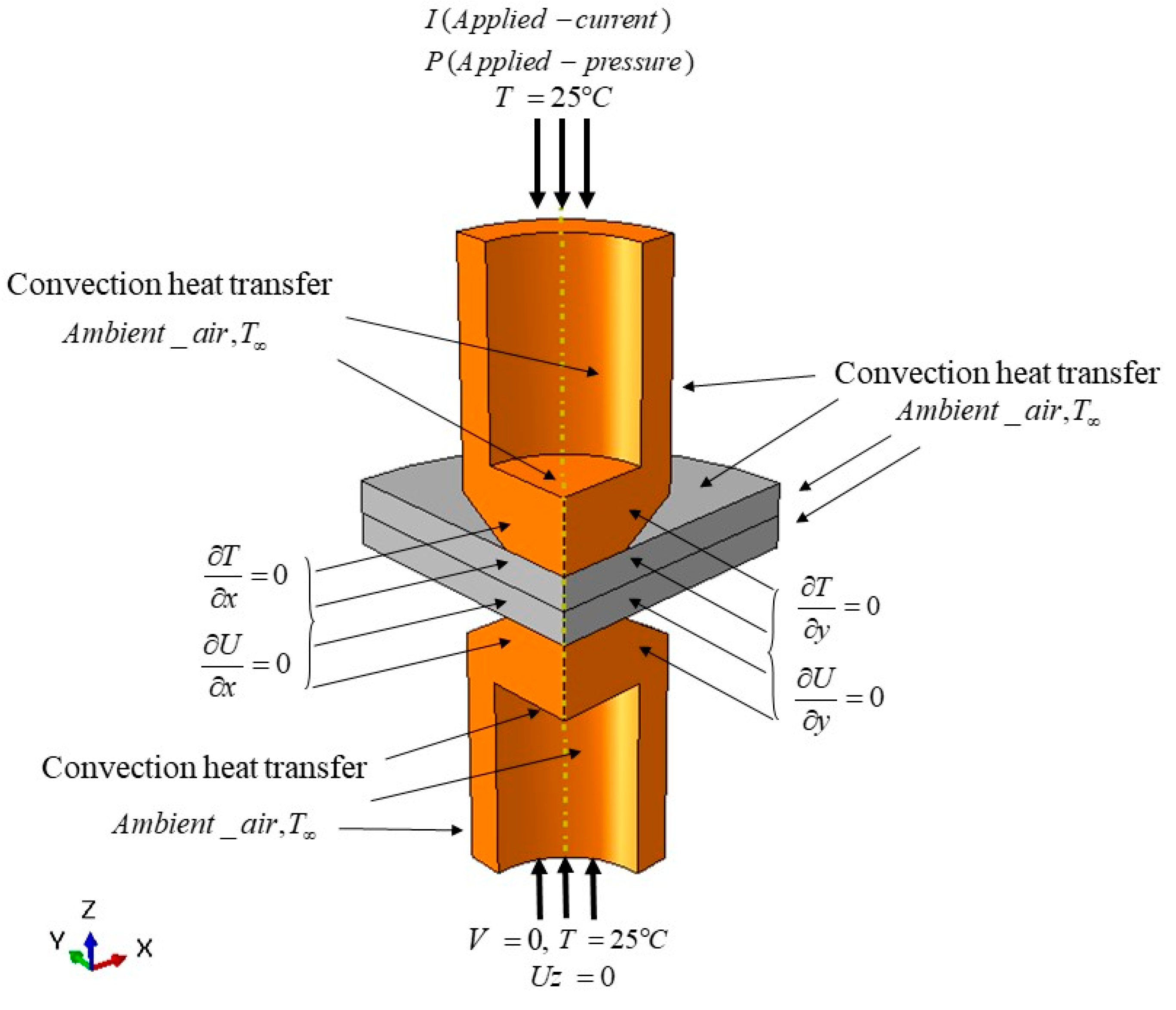
2.4. Boundary Conditions

In numerical analysis, boundary conditions must be properly defined in order to achieve realistic results. The imposed boundary conditions used in the finite element model are presented in Figure 5.
The applied electrical, thermal, and mechanical boundary conditions for solving the governing equations are expressed in the following subsections.

2.4.1. Mechanical Boundary Condition

Mechanical force is applied as a pressure condition at the top of the upper electrode. It is increased linearly during the squeeze time and kept constant during the welding time. The compressive force between the two electrodes causes the two sheets to contact. The bottom surface of the lower electrode is constrained in the z-direction.
According to the axisymmetric nature of geometry, angular displacement is zero and the radial displacement along the central axisymmetric axis of the model is zero.

2.4.2. Electrical Boundary Condition

The electrical input is imposed as an electrical potential at the top surface of the upper electrode relative to the zero reference potential at the bottom surface of the lower electrode.
Heat generation at the faying surface during RSW is a result of contact resistance of two sheets. Since mathematical modeling of contact conditions at the interface of the sheets is important, different theories have been developed for modeling contact resistance. In this paper, a practical representation of electrical contact resistance, which was introduced by Tsei et al., was considered. This model can be expressed by Equation (4).
R c ( T ) = R c ( 20 ° C ) σ Y ( T ) σ Y ( 20 ° C )
where Rc (T) and σY (T) are electrical contact resistance and yield strength at T °C, respectively. According to our measurement, by applying 5.4 kN electrode force at 20 °C, the electrical contact resistance at the electrode–workpiece interface and sheets-faying surface is 30 µΩ and 8 µΩ for AlSi-coated and 24 µΩ and 6 µΩ for uncoated steel, respectively.

2.4.3. Thermal Boundary Condition

According to the axisymmetric conditions of the model, the angular temperature gradient is zero. On the lateral surfaces of the electrodes and sheets in contact with the ambient air, and also the inner surfaces of electrodes in contact with air, the boundary conditions of heat transfer are convective. The temperature of ambient air stays constant during the welding process. In this study, the amount of convection and temperature of ambient air was taken as 15 W/m2·K.

3. Results and Discussion

The weld nugget size is often considered as a criterion for the quality and strength of spot-welded joints. In this study, an incrementally coupled electro-thermo-mechanical analysis was used to simulate the formation of RSW joints on PHS in order to predict the nugget size of the weldment. In our simulations, the weld nugget can be determined by the region that experiences the melting temperature during the welding process. Among different RSW parameters, time and current have the most influence on the nugget size. According to this fact, in this section, the effect of welding time and welding current on nugget formation of RSW joints on PHS in both coated and uncoated forms is studied and compared with experimental results.
Figure 6 and Figure 7 show the temperature distribution and nugget growth of the weldment at the end of applying 7 kA in three pulses each with seven cycles for uncoated and AlSi-coated samples, respectively. The maximum temperature in the weld zone is at the middle of the samples. The red color region, which experiences the melting point (1480 °C) of base metal, specifies the nugget dimensions.
Comparison between Figure 6 and Figure 7 indicates that the difference between temperature profiles despite applying the same welding parameter is due to the effect of AlSi coating, which can change the electrical contact resistance. This shows that the coating plays a critical role in electrical contact resistance and nugget formation during RSW. By changing welding parameters and boundary conditions, the temperature profile determining the weld nugget dimensions could be changed. To validate the FEM model, some experimental spot weld tests have been performed to compare with simulation results. The images of weld nuggets are from the metallographic analyses of the welded zone based on the difference in its microstructure compared to other regions. Figure 8 shows a comparison between the experimental and predicted weld nugget dimensions at a welding current of 8.33 kA and a welding time of three pulses each with five cycles for uncoated steel.
Figure 9 shows a comparison between experimental and predicted weld nugget dimensions at a welding current of 8.55 kA and a welding time of three pulses each with seven cycles for AlSi-coated steel.
As shown in these figures, a good agreement is observed between the finite element predictions and experimental measurements. In order to investigate the effect of welding current and welding time on nugget dimensions, some spot weld simulations and experimental tests were performed on both types of materials by applying different combination of welding parameters.
Figure 9 shows the effects of welding current on the nugget diameter of spot-welded AlSi coated and uncoated specimens at 5.7 kN of electrode force and nine cycles of welding time each of three pulses. According to the ANSI/AWS/SAE/D8.9-97 (1997) standard, the minimum acceptable nugget diameter is defined as 4 t , so due to 1.8 mm thickness of the sheets, the minimum weld nugget diameter would be at least 5.4 mm which is shown by the dotted line in Figure 10.
The results indicate that the minimum acceptable nugget diameter for AlSi-coated samples initiated at the welding current higher than 7.0 kA. Then nugget dimensions raised with increasing welding current until the expulsion occurred at 9.3 kA, while the minimum acceptable diameter for uncoated samples initiated at the welding current higher than 7.6 kA and the first expulsion occurs at 10.2 kA of welding current. In both materials, as the welding current increases, the nugget size increases but the nugget growth rate decreases.
By increasing weld nugget dimensions, the faying contact area of the sheets enlarges and consequently the current intensity reduces which causes a reduction in the heat generation rate at the faying surface of workpieces.
Figure 11 indicates the effects of welding time on the nugget diameter of spot-welding both types of specimens by applying 10.5 kA at 5.7 kN of electrode force in three pulses. The results show that the minimum acceptable nugget diameter initiated after five cycles for the AlSi-coated and seven cycles for the uncoated specimen. With increasing welding time, the dimensions of weld nugget growth continued until the expulsion happened at welding time more than 13 cycles.
As shown in Figure 11, by increasing welding time, the rate of weld nugget growth decreases. This is because of increasing heat transfer with increasing welding time, which causes more heat losses from the weld zone by conduction, convection, and radiation. It was observed that the nugget size for both types of materials increasesd with increasing welding current and time. Comparison between Figure 10 and Figure 11 indicates that the weld nugget diameter was more sensitive to welding current than welding time, which can be explained by the Joule heating phenomenon. In the Joule heating formula, the welding current has the greatest effect on the generation of heat at the faying surface, and there is a direct correlation between heat generation and nugget size in the RSW process.
Based on the results in the present study, it was seen that by applying the same parameters, the formed nugget for coated steel is larger than for uncoated steel. The welding current for attaining the minimum acceptable nugget diameter is less for AlSi coated steels than that for uncoated steels. On the other hand, the maximum applicable welding current for the coated steel is more limited than the uncoated steel, since expulsion occurs at a lower welding current for coated steel in comparison with uncoated steel. These findings indicate that when applying the same welding parameters, the level of produced heat at the faying interface of coated steel is higher than uncoated steel. Since electrical contact resistance is a surface property, coatings can affect the behavior of RSW of steel sheets. According to some published work, the dynamic electrical resistance of AlSi-coated hot-stamped steel was higher than uncoated hot-stamped steel during the weld time [26]. Saha et al. [27] reported that the presence of AlSi coating in the faying interface results in inhomogeneous current flow and violent heat production, in agreement with the earlier occurrence of expulsion presented here. To further understand this issue, the components of electrical contact resistance for an AlSi-coated steel after hot stamping is explained. Electrical contact resistance is generally composed of film resistance and constriction resistance. Film resistance results from electrical bulk resistance of the material, and constriction resistance relates to the contact surface, which depends upon surface hardness. In the case of AlSi-coated steel, after hot stamping, the AlSi coating reacts with the substrate steel, gradually becomes enriched with Fe, and finally transforms into a layer structure consisting of continuous Fe(Al, Si) and intermetallic phases such as FeAl2 and Fe2SiAl2 in a solid solution that influences the electrical resistance of the coating due to their intrinsic physical properties and their influence on the coating surface hardness. These phases are much harder than the substrate, and their roughness is also higher than that of the uncoated surface, which causes the portion of constriction resistance in electrical contact resistance to increase. Because of the low thickness of the coating, the portion of film resistance in electrical contact resistance related to the bulk electrical resistance of the coating material is unnoticeable. Therefore, Al-Si coating on the surface of hot-stamped steel causes the electrical contact resistance at the faying surface to increase due to high constriction resistance resulting from high surface hardness. Due to the effect of AlSi coating on weldability of the material, it would be important to develop a model to predict the behavior of coating according to its specifications such as thickness.

4. Conclusions

In the present work, a three-dimensional axisymmetric finite element model of RSW is generated to predict temperature distribution and nugget growth in spot welded joints for two types of PHS: uncoated and AlSi-coated 1.8 mm Usibor 1500 boron steel after heat treatment similar to that in hot stamping. A fully coupled electro-thermo-mechanical analysis was conducted to investigate the effects of welding current and time on nugget diameter. Furthermore, some experimental spot welds were performed to validate the simulation results by comparing nugget sizes. The calculated weld nugget sizes show good agreement with experimental measurements. The FEM model developed in the present study can be used to optimize the RSW parameters for this kind of material without performing a large number of physical experiments.
According to the results obtained from this research, the conclusions are as follows.
1-
In the case of AlSi hot-stamped boron steel, because of the existence of some intermetallic phases in the coating, the electrical contact resistance at the faying interface increases. This plays a key role during RSW and affects the weldability of steel.
2-
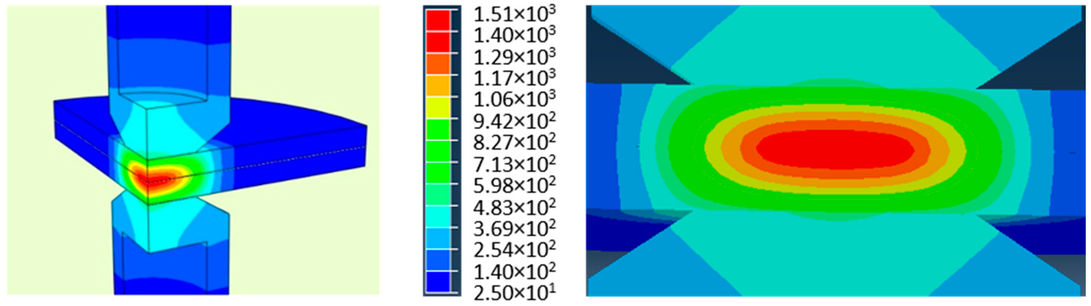
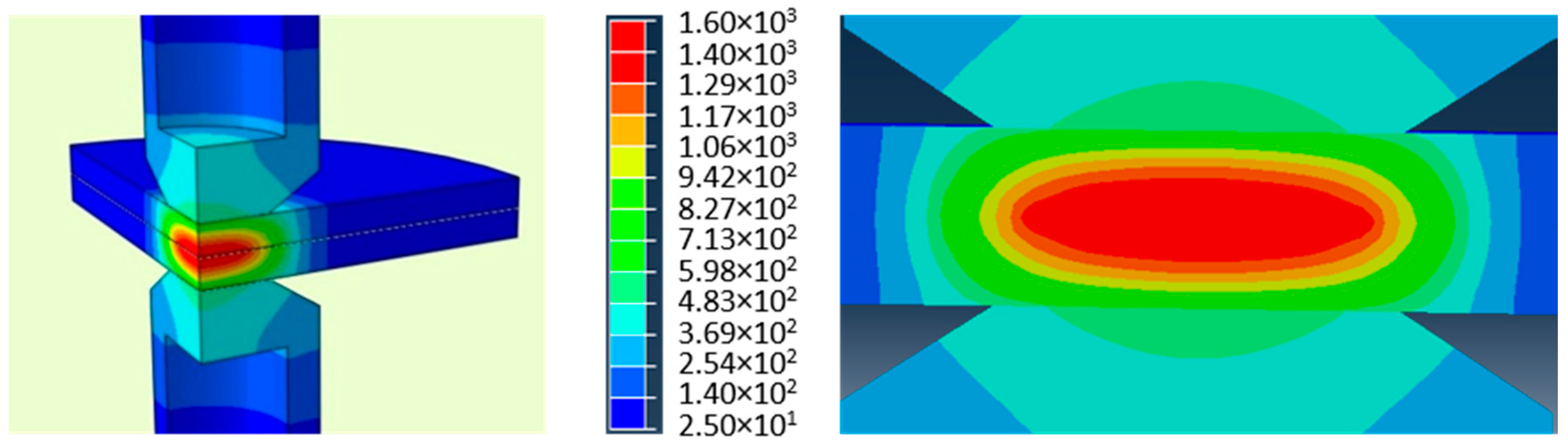
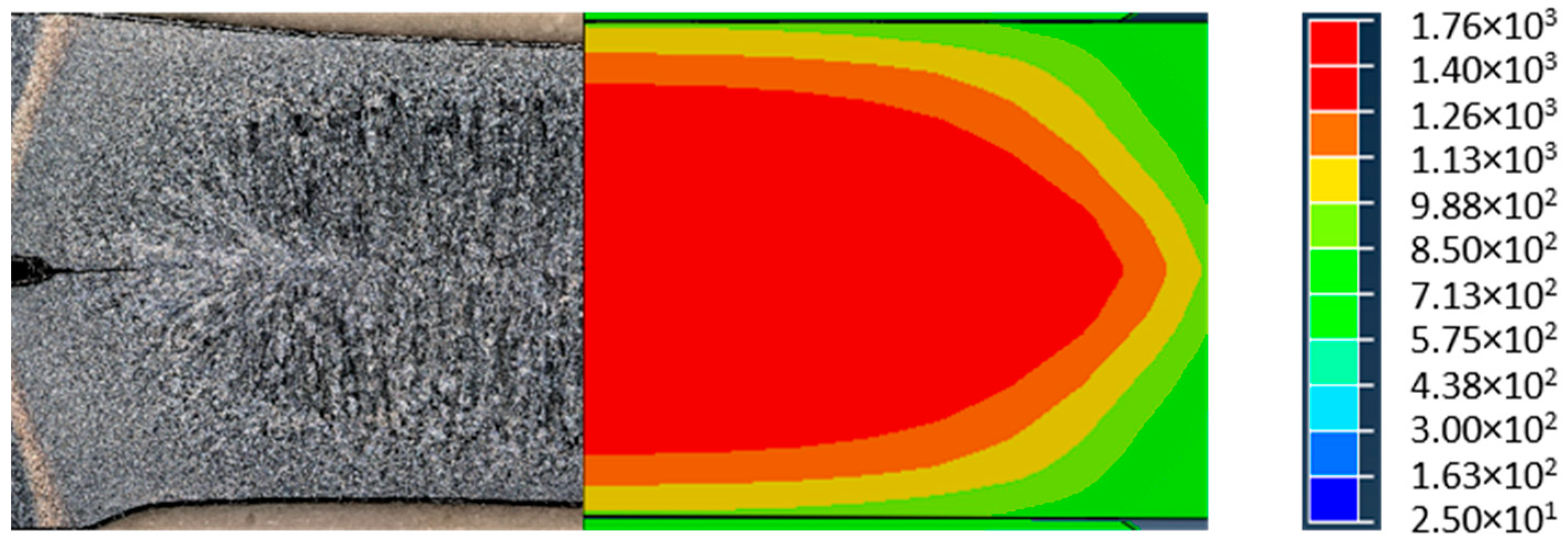
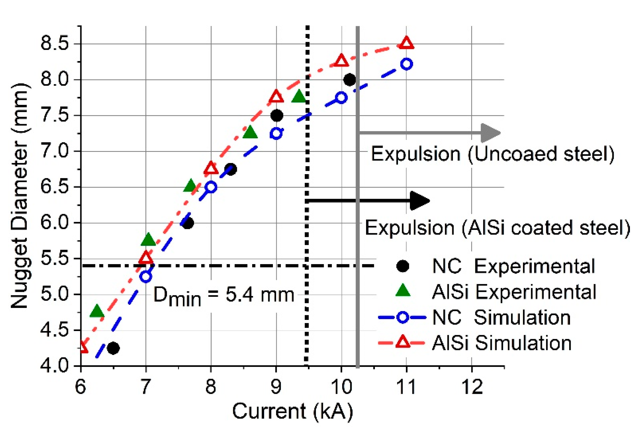
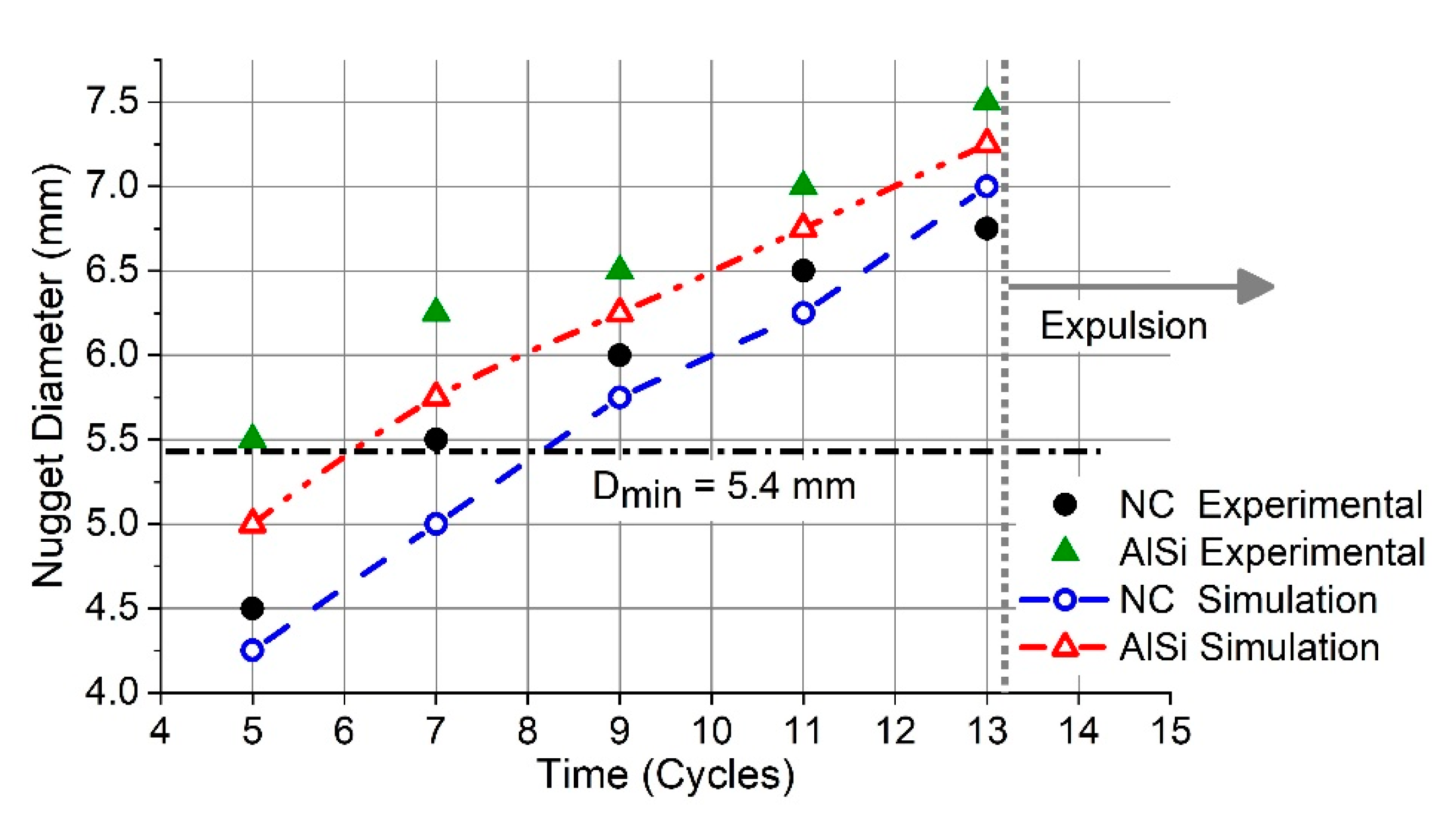
At the same welding parameters, the dimensions of the formed nugget for AlSi-coated steel is larger than for uncoated steel.
3-
AlSi coated steel requires a smaller electrical current for attaining the minimum nugget diameter in comparison with uncoated steel.
4-
The maximum welding current for an expulsion-free welded joint for uncoated steel is higher than for AlSi-coated steel.

Author Contributions

Conceptualization, A.A. and M.H.; methodology, A.A. and M.H.; software, A.A.; validation, A.A.; investigation, A.A., M.H. and C.V.N.; writing—original draft preparation, A.A.; writing—review and editing, A.A., M.H. and C.V.N.; visualization, A.A.; supervision, M.H. and C.V.N. All authors have read and agreed to the published version of the manuscript.

Funding

This research received no external funding.

Data Availability Statement

The data presented in this study are available on request from the corresponding author.

Conflicts of Interest

The authors declare no conflict of interest.

References

  1. Huh, H.; Kang, W. Electrothermal analysis of electric resistance spot welding processes by a 3-D finite element method. J. Mater. Process. Technol. 1997, 63, 672–677. [Google Scholar] [CrossRef]
  2. Chao, Y.J.; Wang, K.; Miller, K.; Zhu, X.-K. Dynamic separation of resistance spot welded joints: Part I—Experiments. Exp. Mech. 2010, 50, 889–900. [Google Scholar] [CrossRef]
  3. Kim, C.; Kang, M.; Park, Y. Laser welding of Al-Si coated hot stamping steel. Procedia Eng. 2011, 10, 2226–2231. [Google Scholar] [CrossRef] [Green Version]
  4. Suehiro, M.; Maki, J.; Kusumi, K.; Ohgami, M.; Miyakoshi, T. Properties of Aluminized Steels for Hot-Forming; 0148-7191; SAE Technical Paper: Warrendale, PA, USA, 2003. [Google Scholar]
  5. Karbasian, H.; Tekkaya, A.E. A review on hot stamping. J. Mater. Process. Technol. 2010, 210, 2103–2118. [Google Scholar] [CrossRef]
  6. Sun, X.; Khaleel, M.A. Dynamic strength evaluations for self-piercing rivets and resistance spot welds joining similar and dissimilar metals. Int. J. Impact Eng. 2007, 34, 1668–1682. [Google Scholar] [CrossRef]
  7. Zhou, M.; Zhang, H.; Hu, S. Relationships between quality and attributes of spot welds. Weld. J. N. Y. 2003, 82, 72-S. [Google Scholar]
  8. Zhang, H.; Senkara, J. Resistance Welding: Fundamentals and Applications; CRC Press: Boca Raton, FL, USA, 2011. [Google Scholar]
  9. Cha, J. A Study on Resistance Spot Weldability of Aluminum Coated Sheet Steels. Master’s Thesis, Pukyong National University, Busan, Korea, 2002. [Google Scholar]
  10. Gould, J. An examination of nugget development during spot welding, using both experimental and analytical techniques. Weld. J. 1987, 66, 1s–10s. [Google Scholar]
  11. Tsai, C.; Papritan, J.; Dickinson, D.; Jammal, O. Modeling of resistance spot weld nugget growth. Weld. J. 1992, 71, 47. [Google Scholar]
  12. Tsai, C.; Jammal, O.; Dickinson, D. Study of nugget formation in resistance spot welding using finite element method. In Proceedings of the 2nd International Conference on Trends in Welding Research, Materials Park, OH, USA, 1–5 June 1998. [Google Scholar]
  13. Chang, B.; Zhou, Y. Numerical study on the effect of electrode force in small-scale resistance spot welding. J. Mater. Process. Technol. 2003, 139, 635–641. [Google Scholar] [CrossRef]
  14. Nied, H. The finite element modeling of the resistance spot welding process. Weld. J. 1984, 63, 123. [Google Scholar]
  15. Cho, H.; Cho, Y. A study of the thermal behavior in resistance spot welds. Weld. J. 1989, 68, 236s–244s. [Google Scholar]
  16. Eisazadeh, H.; Hamedi, M.; Halvaee, A. New parametric study of nugget size in resistance spot welding process using finite element method. Mater. Des. 2010, 31, 149–157. [Google Scholar] [CrossRef]
  17. Moshayedi, H.; Sattari-Far, I. Resistance spot welding and the effects of welding time and current on residual stresses. J. Mater. Process. Technol. 2014, 214, 2545–2552. [Google Scholar] [CrossRef]
  18. Nielsen, C.; Zhang, W.; Alves, L.; Bay, N.; Martins, P. Coupled Finite Element Flow Formulation. In Modeling of Thermo-Electro-Mechanical Manufacturing Processes; Springer: Berlin/Heidelberg, Germany, 2013; pp. 11–36. [Google Scholar]
  19. Nielsen, C.V.; Zhang, W.; Perret, W.; Martins, P.A.; Bay, N. Three-dimensional simulations of resistance spot welding. Proc. Inst. Mech. Eng. Part D: J. Automob. Eng. 2015, 229, 885–897. [Google Scholar] [CrossRef]
  20. Cheon, J.Y.; Vijayan, V.; Murgun, S.; Do Park, Y.; Kim, J.H.; Yu, J.Y.; Ji, C. Optimization of pulsed current in resistance spot welding of Zn-coated hot-stamped boron steels. J. Mech. Sci. Technol. 2019, 33, 1615–1621. [Google Scholar] [CrossRef]
  21. Ji, C.-W.; Jo, I.; Lee, H.; Choi, I.-D.; Do Kim, Y.; Park, Y.-D. Effects of surface coating on weld growth of resistance spot-welded hot-stamped boron steels. J. Mech. Sci. Technol. 2014, 28, 4761–4769. [Google Scholar] [CrossRef]
  22. Ighodaro, O.; Biro, E.; Zhou, Y. Comparative effects of Al-Si and galvannealed coatings on the properties of resistance spot welded hot stamping steel joints. J. Mater. Process. Technol. 2016, 236, 64–72. [Google Scholar] [CrossRef]
  23. Lövenborn, D. 3D FE Simulations of Resistance Spot Welding; KTH Royal Institute of Tchnology: Stockholm, Sweden, 2016. [Google Scholar]
  24. Zhang, P.; Zhu, L.; Xi, C.; Luo, J. Study on Phase Transformation in Hot Stamping Process of USIBOR® 1500 High-Strength Steel. Metals 2019, 9, 1119. [Google Scholar] [CrossRef] [Green Version]
  25. Moshayedi, H.; Sattari-Far, I. Numerical and experimental study of nugget size growth in resistance spot welding of austenitic stainless steels. J. Mater. Process. Technol. 2012, 212, 347–354. [Google Scholar] [CrossRef]
  26. Ji, C.-W.; Choi, I.; Kim, Y.D.; Park, Y.-D. Study on coating melting behavior on weld growth mechanism for Al-Si coated hot-stamped boron steels in resistance spot welding. Korean J. Met. Mater. 2014, 52, 931–941. [Google Scholar]
  27. Saha, D.; Ji, C.; Park, Y. Coating behaviour and nugget formation during resistance welding of hot forming steels. Sci. Technol. Weld. Join. 2015, 20, 708–720. [Google Scholar] [CrossRef]
Figure 1. Photographs for thermal processing of the samples (a) Putting specimens in a furnace; (b) Setting the temperature to 910 °C; (c) Taking the austenitized specimens out of the furnace after 6 min; (d) Specimens after quenching.
Jmmp 05 00010 g001
Figure 2. Microstructure of material and appearance of AlSi coating (a) as-received condition; (b) after heat treatment similar to the hot-stamped condition.
Jmmp 05 00010 g002
Figure 3. Measurement setup for electrical contact resistance.
Jmmp 05 00010 g003
Figure 4. Initial mesh of the developed model.
Jmmp 05 00010 g004
Figure 5. Boundary conditions in the axisymmetric resistance spot welding (RSW) model.
Jmmp 05 00010 g005
Figure 6. A typical temperature distribution of the weldment at the end of RSW of uncoated steel. The scale bar shows the temperature in degrees Celsius.
Jmmp 05 00010 g006
Figure 7. A typical temperature distribution of the weldment at the end of RSW of AlSi-coated steel. The scale bar shows the temperature in degrees Celsius.
Jmmp 05 00010 g007
Figure 8. A representative comparison between (a) experimental and (b) numerical weld nugget size for uncoated steel. The scale bar shows the temperature in degrees Celcius.
Jmmp 05 00010 g008
Figure 9. A representative comparison between (a) experimental and (b) predicted weld nugget size for AlSi coated steel. The scale bar shows the temperature in degrees Celsius.
Jmmp 05 00010 g009
Figure 10. A representative comparison between experimental and predicted weld nugget sizes for AlSi coated steel and non-coated (legend: NC) steel.
Jmmp 05 00010 g010
Figure 11. A representative comparison between experimental and predicted weld nugget sizes for AlSi-coated steel and non-coated (legend: NC) steel. The welding time axis represents the number of cycles in each of the three pulses, such that the total welding time is found by multiplying by 3.
Jmmp 05 00010 g011
Table 1. Chemical composition of Usibor 1500 boron steel.
SteelChemical Composition in wt%
FeCMnSiCrB
Uncoated steel980.251.140.270.190.003
Al-Si coated steel980.231.140.270.180.003
Table 2. Mechanical and physical properties of hot-stamped boron steel [23,24].
Temp.
(°C)
Density
(kg/m3)
Electrical Resistivity µ·ΩmThermal Conductivity
(W/m·K)
Specific Heat
(J/kg·K)
Thermal
Expansion Co.
(10−6 × K−1)
Yield Stress (MPa)Flow Stress at 0.4 of Strain
(MPa)
Young’s Modulus
(GPa)
2079000.3626.21712501840200
10078800.41228.346117.412101820193
20078300.46331.54951811501800185
40077500.65130.153319.110801300176
60076600.90827.164819.67001200167
80075601.1225.267520.2480900159
100075101.1927.450020.4400800151
120073701.2331.320.720040060
140073201.2734.721.39020020
150073201.2823621.62010
Table 3. Mechanical and physical properties of the employed copper electrode [25].
Temp.
(°C)
Density
(kg/m3)
Electrical Resistivity 10−9·ΩmThermal Conductivity
(W/m·K)
Specific Heat
(J/kg·K)
Thermal Expansion Co. (10−6 × K−1)Yield Stress
(MPa)
Young’s Modulus
(GPa)
Poisson’s Ratio
10890026.4390.339716.5831240.32
9330380.640216.7105
20440370.141917.193
31650.5355.143117.582
42761.9345.444017.855
53869.9334.946518.438
6498032047718.525
76089.8315.518.916
87194.8310.319.314
98299.83055027
Publisher’s Note: MDPI stays neutral with regard to jurisdictional claims in published maps and institutional affiliations.

