Article

Influence of Softening Mechanisms on Base Materials Plastic Behaviour and Defects Formation in Friction Stir Lap Welding

1
Universidade de Coimbra, CEMMPRE, Departamento de Engenharia Mecânica, Rua Luís Reis Santos, 3030-788 Coimbra, Portugal
2
ISEL, Department of Mechanical Engineering, Polytechnic Institute of Lisbon, Rua Conselheiro Emídio Navarro 1, 1959-007 Lisboa, Portugal
3
Universidade de Coimbra, ISISE, Departamento de Engenharia Mecânica, Rua Luís Reis Santos, 3030-788 Coimbra, Portugal
*
Author to whom correspondence should be addressed.
J. Manuf. Mater. Process. 2020, 4(4), 120; https://doi.org/10.3390/jmmp4040120
Submission received: 15 October 2020 / Revised: 7 December 2020 / Accepted: 10 December 2020 / Published: 13 December 2020
(This article belongs to the Special Issue Friction Stir Welding and Related Technologies)

Abstract

:
The AA6082-T6 and AA5754-H22 aluminium alloys were selected as the base materials to fabricate similar and dissimilar friction stir lap welds. Three lap configurations, AA6082/AA5754, AA5754/AA6082 and AA6082/AA6082, were produced using three pin profiles and tested to analyse the role of the plastic behaviours of the base materials on the welding conditions. The macrostructural characterisation was carried out to understand the material flow response and hook defect formation. The mechanical characterisation of the joints was done by microhardness and lap tensile shear testing. The finite element analysis and phase simulation were conducted to predict the phase dissolution temperatures and the softening kinetics. The welding torque and axial forces registered were analysed to quantify differences in the alloy’s flowability during welding. The analysis of the welding machine outputs enabled to conclude that higher axial forces were registered when the AA5754 alloy was placed at the top of the dissimilar lap joint, showing that the non-heat-treatable alloy has lower flowability than the heat-treatable alloy. These results were associated with the flow-softening of the AA6082 alloy in plastic deformation at high temperatures. The coupled experimental and numerical analysis revealed that the plastic behaviour of the base materials strongly influenced the material flow and, in this way, the hook defect formation and the shear tensile properties of the welds.

1. Introduction

The outstanding property combinations of aluminium makes it a very relevant material for many industries, such as the automotive, shipbuilding, railway, etc. With the development of solid-state welding processes, such as friction stir welding (FSW), the joining of aluminium has become more efficient and much less complex. However, although a very relevant increase in knowledge has been achieved in the FSW of aluminium and its alloys over the last 30 years, there are many aspects that still need to be more explored, especially in which concerns the joining of aluminium alloys with different properties, such as the heat-treatable AA6XXX and non-heat-treatable AA5XXX aluminium alloys. The optimisation of the welding parameters requires the full understanding of the thermomechanical phenomena occurring during the welding of these alloys, which strongly depends on their plastic behaviour at high temperatures and strain rates [1,2]. In spite of significant research that has been conducted on dissimilar welding of AA5XXX and AA6XXX aluminium, most of the published works were focused on butt joining. For this joint configuration, numerical and experimental studies have been developed in order to understand the influence of the rotation and traverse speeds [3,4], tool design [5,6] and relative positioning of the base materials [7] on the welding conditions. The morphological, microstructural and mechanical properties of the butt welds have already been characterised by some authors [8,9,10,11].
Regarding AA5XXX/AA6XXX friction stir lap welding (FSLW), the research is much more incipient, and it has been essentially developed over the last five years. Costa et al. [12] conducted one of the first works focused on dissimilar lap welding of these alloys. The authors reported a strong influence of the base materials positioning on the hook defect formation and, therefore, on the weld strength. The influence of the base materials’ relative positioning on the weld strength was also studied by Yoon et al. [13] in A6111/A5023 welding. However, unlike that concluded by Costa et al. [12], the maximum tensile–shear load was reported to be obtained for welds in which the non-heat-treatable A5023 alloy was located at the top of the lap joint, which makes the influence of base materials positioning on the lap weld quality still an open question.
The morphology of dissimilar AA5XXX/AA6XXX friction stir lap welds was especially addressed by Yoon et al. [14]. The formation of onion ring structures in the nugget of the welds was found to be strongly correlated to the use of a threaded pin. Moreover, the authors reported that the formation of voids in these welds results from the coupled effect of the remnant of the original interface between the base materials and the asymmetrical material flow around the tool. In turn, Park et al. [15] studied the effect of the shoulder diameter and the rotation and traverse speeds on the tensile–shear strength of AA6111/AA5023 lap welds. According to these authors, the maximum tensile–shear load was obtained by welding with a shoulder diameter of 10 mm and with a traverse-to-rotation speeds ratio of 0.9 mm/rev.
A numerical simulation is another tool to study the different responses of the dissimilar materials. Tang and Shen [16] simulated the FSLW of dissimilar aluminium materials and observed a drastic change in temperature distribution at the interface due to differences in specific heat capacities, viscosity and thermal conductivity. In another similar work, Hamilton et al. [17] observed a difference in temperature evolution and material flow between dissimilar aluminium materials. The study also related the temperature distribution with the different precipitate availability and hardness recorded in the various zones. The temperature evolution in the AA5086/AA6061 FSW was predicted by Jamshidi et al. [18] and concluded that the loss in hardness at the AA6061 side was attributed to the attainment of the precipitate dissolution temperature.
In spite the diversity of the studies/results on dissimilar aluminium alloy friction stir lap welding, the relationship between the heat-treatable alloys softening at a high temperature, its plastic behaviour and the welding thermomechanisms is a topic which remains almost unexplored in FSW literature. In this research, the characterisation of the weld morphology and mechanical properties were used as tools to assess the material flow during welding and the presence and severity of lap-welding defects. Then, the flowability of the base materials in dissimilar welding was assessed by process output analysis. Finally, numerical simulation tools were used to determine the thermal cycles and the AA6082-T6 precipitation kinetics associated with them. Based on these results, defect formation mechanisms were related to the plastic properties at high temperatures of the heat-treatable alloys and base materials’ relative positioning in the joint.

2. Experimental Procedure

Dissimilar lap welds were produced using 1 mm thick plates of heat-treatable (AA6082-T6) and a non-heat-treatable (AA5754-H22) aluminium alloys in an MTS I-Stir PDS machine (MTS Systems Corp., Eden Prairie, MN, USA) operating in the position control. Similar AA6082-T6 lap welds were also produced using the same equipment and control modes. The evolutions of the torque and of the axial load were recorded during the welding.
The room temperature mechanical properties of the base materials are displayed in Table 1. In the dissimilar welding, two different base material combinations were tested, i.e., whereas some welds were produced with the AA6082 alloy as the top plate, in contact with the welding tool, other welds were produced with the reverse positioning of the base materials. As shown in Figure 1, three tools, with different pin geometries, were used in the investigation. In the text, each tool will be identified according to the pin design (CN and CL for the conical and cylindrical pin geometry, respectively) and the pin tip diameter. The welding parameters, which are displayed in Table 2, were defined based on the work conducted by Costa et al. [19]. In the next section, the similar welds (S) will be labelled as S6, and the dissimilar welds (D) will be identified according to the base materials positioned in the lap joint. So, the D65 nomenclature will be used to identify the joints produced with the AA6082 and AA5754 alloys as the top and the bottom plates in the joint, respectively, and the D56 for the welds produced with the reverse-base materials positioning.
After welding, cross-section samples were collected from the welds and prepared following the standard metallographic procedures. The morphological characterisations of the welds were conducted by optical microscopy (OM) and scanning electron microscopy (SEM) using Leica DM4000M LED (Leica Microsystems, Wetzlar, Germany) and PHILIPS XL30 SE (Philips, Eindhoven, The Netherlands) microscopes, respectively. The local weld properties and the joint strengths were assessed by microhardness and lap tensile–shear testing, respectively. The microhardness measurements (HV0.2) were performed along the transverse cross-section of the welds, at the top and the bottom of the lap joint (at middle thickness), using a Struers Duramin tester (Struers, Ballerup, Denmark). The lap tensile–shear tests were performed in quasistatic loading conditions (5 mm/min), using a 5-kN universal testing machine Shimadzu Autograph AG-X (Shimadzu, Kyoto, Japan). Two loading modes were tested in order to quantify the strength mismatch between the advancing (AS) and retreating (RS) sides of the welds. Schematics of both loading modes (AS and RS loading) are illustrated in Figure 2. During testing, the strain distribution in the specimens was acquired by digital image correlation (DIC) using GOM Aramis 5M (GOM, Braunschweig, Germany). The specimens were prepared following the procedures reported in Leitão et al. [1].

3. Numerical Simulation Methodology

A thermomechanical analysis of the AA6082-T6 similar lap welding was done using the finite element (FE) package COMET [20] in order to correlate the maximum temperature distribution in the lap joints with the precipitation kinetics of the alloy in the different lap weld regions. Since, in the analysis of the experimental results, the properties of the S6 weld were used as a reference for comparison with the dissimilar ones, in the numerical simulation work, only the similar lap welding of the heat-treatable aluminium alloy, with the CN8 tool, was simulated.
The base material plastic behaviour was modelled using the Norton-Hoff constitutive model:
σ e q ( ε ˙ e q , T ) = 3 μ ( T ) ( 3 ε ˙ e q ) m ( T ) ,
in which σeq is the equivalent stress, ε ˙ e q is the equivalent strain rate and µ(T) and m(T) are parameters that determine the strength and the strain rate sensitivity, respectively, of the base material. The constitutive law parameters were taken from Dialami et al. [21], following the recommendations presented by Andrade et al. [22]. The temperature-dependent thermal properties of the base material, i.e., the thermal conductivity, specific heat and density, were also taken from Dialami et al. [21].
Norton’s friction law:
τ = a(T) ‖Δvsq−1Δvs,
was used to model the friction between the tool and the workpiece. In Equation (2), τ is the friction shear stress, Δ v s is the relative sliding velocity between the tool and the workpiece, q is the sensitivity to the sliding velocity and a ( T ) is the consistency parameter. Both q and a(T) were selected according to Andrade et al. [23].
The model geometry and mesh discretisation are shown in Figure 3. As shown in the figure, in COMET [21], the tool is modelled in a Lagrangian framework, while the stirring zone and the base material are modelled using the Arbitrary Lagrangian/Eulerian (ALE) and Eulerian frameworks, respectively. Based on the experimental results and on the findings from Costa et al. [24], the 1 mm thick lap plates were modelled as a single plate, with 2 mm thickness. The tool was modelled in contact with the upper plate, with only 0.2 mm pin penetration in the bottom half-plate thickness. The full computational model comprised 15,724 nodes and 79,820 tetrahedral elements.
The metallurgical simulation package Thermocalc was used for the prediction of the temperatures at which the phase dissolution occurs for the AA6082-T6 alloy. These data were coupled with the maximum temperatures previewed by COMET in order to determine the precipitation kinetics in the different weld regions and to associate it with local base material softening mechanisms. The weight percentage of the alloy elements of the AA6082 aluminium alloy was used as the input for the metallurgical simulation to plot the phase dissolution curves.

4. Results and Discussion

In the next section, the mechanical and morphological characterisation results will be analysed in order to assess the lap weld defect severities and to relate them with the AA6082 and AA5754 alloy properties and relative positioning in the dissimilar welds. Then, the FSW machine output data (torque and axial force) will be used as parameters for measuring the flowability of the two base materials under the stirring action of the tool. Finally, the flowability of the AA6082 will be explained by analysing, through the numerical simulation results, the influence of the thermal cycles and related precipitation kinetics on the alloy strength and plastic properties at high temperatures.

4.1. Macrostructure and Morphology

Macro- and micrographs of the advancing side of the similar and dissimilar welds produced with the CN8 tool are shown in Figure 4. Since the morphology of the welds was found to be more influenced by the base material positioning in the lap joint than by pin geometry, the macrographs of the welds produced with the CN6 and CL6 tools are not displayed in the figure. The entire cross-sections of the welds are also not shown in the figure, since no macroscopic defects, such as voids or tunnels, were formed in the welds, regardless of the tool geometry or of the base material combinations (S and D welds) and their relative positions in the lap joint (D65 and D56 welds). The morphology of the lap interface, at the retreating side of the welds, was also similar for all the welds and was characterised by a continuous straight interface, with no clear evidence of the base materials stirring across it. Contrary to this, a well-defined hook-shaped interface was observed at the advancing side of the S6 (Figure 4a) and D56 (Figure 4c) welds but not in the D65 weld (Figure 4b). The material discontinuity associated with the hook-shaped interface is well-illustrated in the SEM micrograph displayed in Figure 4d, which corresponds to the region signalised in the cross-section of the D56 weld. The figure shows that the hook corresponds to an unbonded interface, which results from the upward flow of the lower plate material through the lap interface. The similarities between the hook shape in the S6 and D56 welds, as well as the absence of a well-defined hook in the D65 weld, makes also possible to infer that this defect is influenced by the properties of the base materials being joined, as well as by their relative positioning in the lap joint. Since the precise size of the unbonded interface is very difficult to measure, the severity/size of the hook, in the different welds, will be evaluated by comparing the joint strengths.

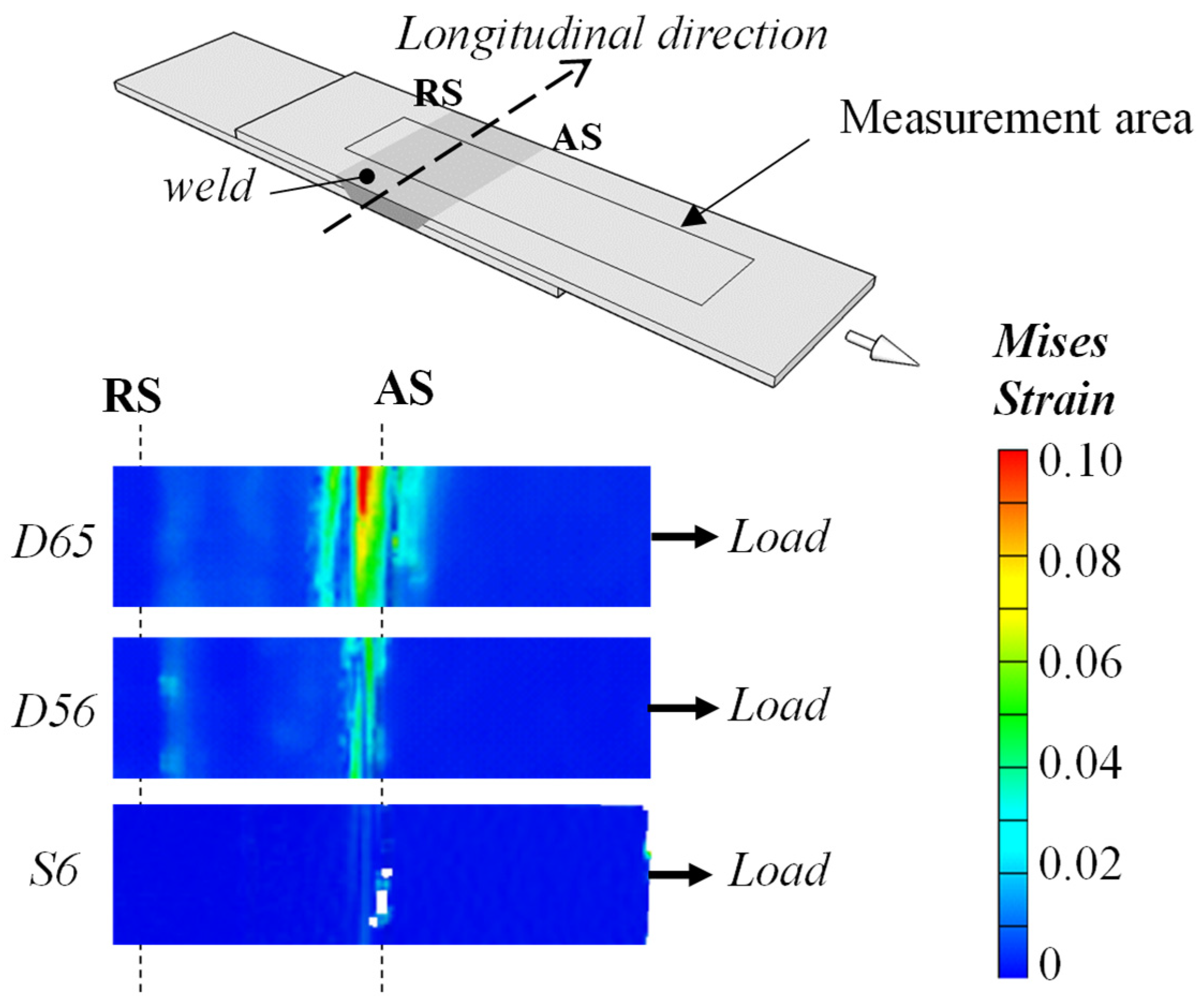
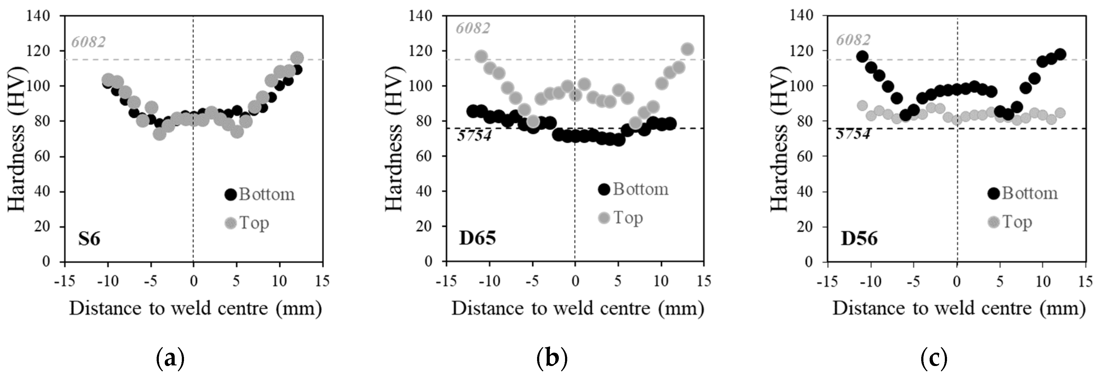
4.2. Mechanical Properties

The normalised maximum loads (NML) for all the welds produced in this work are compared in Figure 5. For each weld, the NML was calculated as the ratio between the maximum load of the joint, obtained from the tensile–shear tests, and the maximum load, in uniaxial tension, of the AA6082 alloy, which is the reference material in this investigation. From Figure 5a–c, it can be concluded that lower NML values were registered for the S6 welds, regardless of the welding conditions (CN6, CL6 or CN8 tools) or of the loading mode (AS or RS). It is also possible to conclude that the NML values of the AS-loaded specimens were lower than that of the RS-loaded specimens for all the S6 welds, which agrees well with the formation of the hook-shaped discontinuity at the advancing side (Figure 4a) independently of the tool used to produce it. The hook-shaped discontinuity reduces the effective thickness of the top plate and, consequently, the load-bearing area of the tested specimens, which is the reason this feature is regularly labelled as a hook defect.
The presence of the hook defect also promoted an important asymmetry in strength between the AS and RS-loaded specimens for all the dissimilar welds, except that produced with the CN8 tool. Figure 5 also shows that the NML values registered for the RS-loaded dissimilar welds were different from those registered for the S6 welds. Despite the similarities in weld morphologies, an improvement in the RS strength, relative to the S6 welds, was noticed for all the welds but mainly for that produced with the CL6 and CN8 tools. These results indicate that mechanical testing is a suitable tool for signalising the presence of lap welding defects not always visible in optical microscopy.
The comparison of the NML values between the dissimilar welds also enables us to conclude that the highest strength values in AS loading were always registered for the D65 welds. These results enabled us to conclude that higher joint strengths can be achieved by combining the AA6082 alloy with the AA5754 alloy and positioning the non-heat-treatable alloy as the bottom plate in the lap joint. The gain in strength associated with this dissimilar base material combination is especially noticeable for the dissimilar joints produced with the CN8 tool, for which a symmetry in strength was registered, as already noticed above. The symmetry in strength between the AS and RS-loaded samples for the CN8 tool is in good agreement with the absence of a well-defined hook-shaped interface in the macrograph of Figure 4b.
The absence of the hook in the D65 welds produced with the CN8 tool is also illustrated in Figure 6, which compares the Von Mises strain maps, at maximum load, for the similar and dissimilar AS-loaded specimens. The figure enables us to observe that the D65 joints had a failure for higher plastic strain values than the S6 and D56 joints due to the absence of severe hook defects acting as stress concentrators. The same did not happen when the AA6082 alloy was positioned as the bottom plate, even when welding with the CN8 tool.
The microhardness profiles, registered along the top and bottom parts of the welds produced with the CN8 tool, are illustrated in Figure 7. The average hardness values of the base materials are also displayed in the figure using dashed lines. In Figure 7a, corresponding to the S6 welds, it can be observed the W-shaped hardness profiles, usually associated with the AA6082-T6 welds. The hardness decrease relative to the base material in both the upper and lower parts of the weld is one of the reasons for the very low NML values registered in the S6 tensile–shear tests. The similarities between the hardness profiles of the upper and lower parts of the weld also indicate that, although the FSW tool was mostly in contact with the upper plate, there was an almost homogeneous heat distribution across the entire lap joint thickness. This assumption supported the decision of modelling the two plates as a single plate with double thickness in the numerical simulation of the similar AA6082 friction stir lap welding.
For the dissimilar welds, different hardness profiles were obtained for the top and bottom parts of the lap joints (Figure 7b,c). However, while similar W-shaped profiles were registered for the AA6082 part of the welds, independent of the base material relative positions in the joint; the same was not registered for the AA5457 part. For this alloy, different hardness values relative to the base material were registered in the weld, according to the dissimilar base material combinations, i.e., when the AA5754 alloy was positioned as the top plate, an increase in hardness relative to the base material was registered. In turn, when this alloy was positioned at the bottom of the joint, no significant changes in the hardness relative to the base material were registered. The hardness increase in the D56 combination showed that the AA5457 alloy was slightly hardened due to the plastic deformation promoted by the tool when the alloy was in contact with it. The increase in the strength of the alloy, relative to the base material, indicated that the stirred material was not fully recovered, resulting in a strain hardened microstructure after welding.

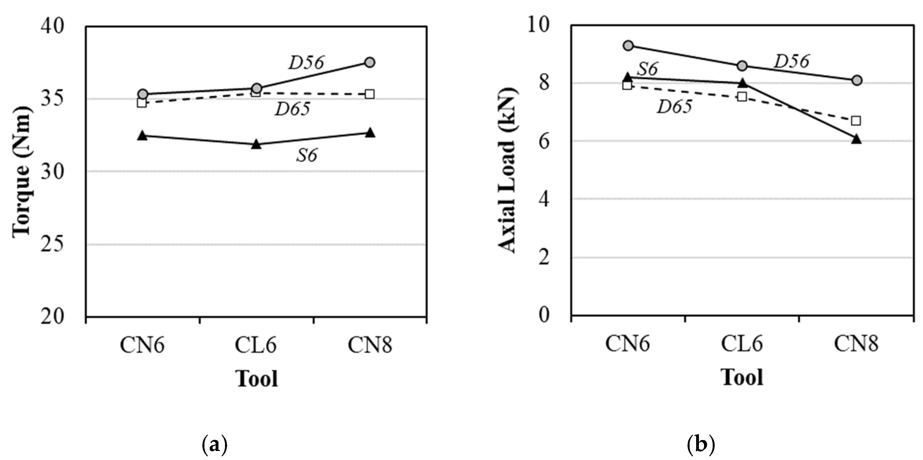
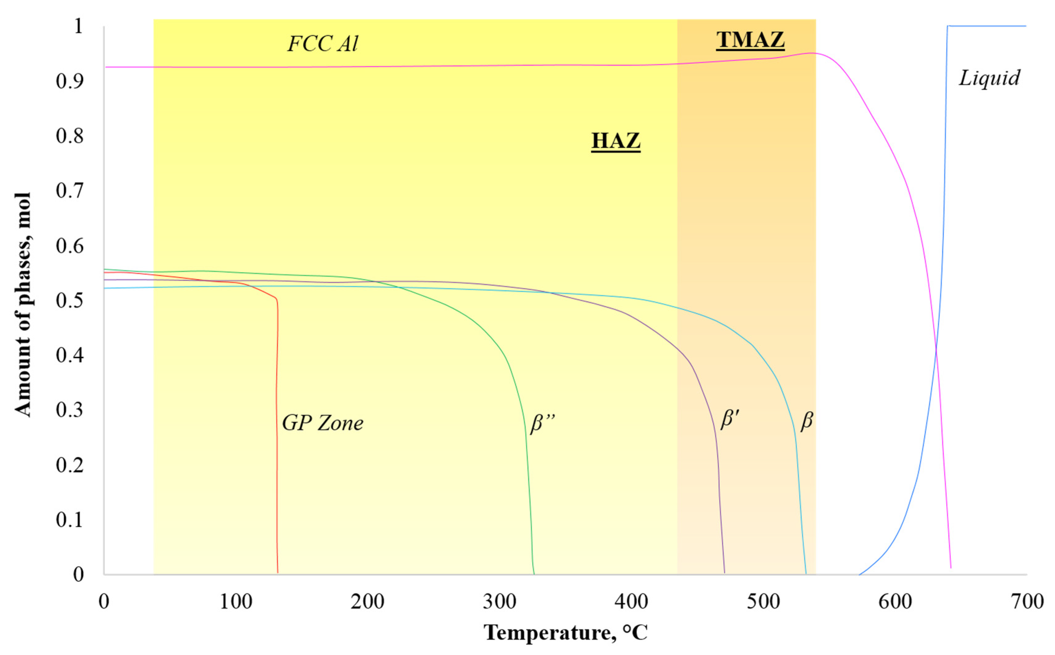
4.3. Thermomechanical Analysis

In order to understand the thermomechanical conditions experienced during welding, the machine output parameters, i.e., the torque and the axial force, were registered and processed. The average torque and axial load values were used to assess the flowability of the base materials during welding, as all the welds were fabricated in the position control. The average values of the torque and axial load, computed considering only the steady-state part of the torque–time and force–time plots, are displayed in Figure 8. From Figure 8a, it can be concluded that the average torque values registered in the dissimilar welding operations were always higher than those registered in the similar welding of the AA6082 alloy. These results show that the presence of the AA5754 alloy, regardless of being located at the bottom or at the top of the lap joint, promoted an increase in the energy required to perform the weld, indicating a strong influence of the base material properties/interactions on the thermomechanical conditions experienced during welding. Since, according to Table 1, at room temperature, the AA5457 alloy had much lower strength than the AA6082 alloy, the base material properties influencing the energy required for the welding have to be related to important differences in the flowability of the base materials during welding, i.e., with differences in the plastic properties of the base materials at the stirring temperature. Actually, analysing the axial load values displayed in Figure 8b, it is possible to conclude that much lower force values were required to maintain the tool in position when the AA6082 alloy was the top plate and/or the CN8 tool was used. Since, as it is well-known, the tool geometry has a strong influence on the material flow, it is again possible to conclude that there was an important influence of the alloy’s flowability (plastic properties) on the required axial force. However, it is also possible to conclude that the load required for maintaining the tool in position is lower when the AA6082 alloy is the top plate, i.e., the base material being stirred by the tool. Lower axial forces must be related to the lower base material resistance to the tool penetration and stirring. Since, as already stated, the AA6082 alloy has a much higher room temperature strength than the AA5457 alloy, the lower resistance of the AA6082 alloy to the stirring has to be related to the thermal softening of the heat-treatable alloy under the thermal cycles imposed during welding.
The temperature distributions in the longitudinal and the transverse cross-sections of the similar AA6082 welds, determined using the FE-based analysis, are shown in Figure 9. From the figure, it can be concluded that strong temperature gradients were previewed across the longitudinal and the transverse sections of the welds. It is also possible to observe that peak temperature values of about 550 °C and 450 °C were determined to be reached in the stir zone and at the TMAZ/HAZ interface, respectively.
The precipitation kinetics of the AA6082 alloy was predicted, using Thermocalc software, to be as illustrated in Figure 10, where the phase dissolution curves are correlated with the maximum temperatures in the different weld zones, represented by coloured squares. From the figure, it was concluded that the predicted dissolution temperatures of the second-phase particles are 133 °C for the Guinier–Preston (GP) zones and 325 °C, 468 °C and 530 °C for the β”, β’ and β precipitates, respectively. The figure also shows that the temperatures in the TMAZ were in the same range of the dissolution temperature of the second-phase particles, which is corroborated by the hardness profiles in Figure 7 for this alloy. The predicted dissolution temperatures also well-agree with the transmission electron metallographic (TEM) study made by Sahil et al, where the microstructure contained dissolution zones and recorded the lowest hardness [25]. Similar observations relating to precipitates with hardness were also reported by Jandaghi et al. [26], and, therefore, the lowest hardness recorded at the TMAZ of AA6082 was attributed to the absence of strengthening precipitates. On the other hand, the SZ recorded a slightly higher hardness than TMAZ; this is due to the attainment of a higher temperature than TMAZ (Figure 9), which is sufficient for dissolution, followed by the formation of a GP zone. This inference is confirmed with the similar observation in a TEM study made by Xu et al. where the formation of GP zones were more related to the hardness increments than the TMAZ zone [27].
Since the hook formation results from the upward material flow at the advancing side of the tool [28], it can be inferred that the formation of this defect will be facilitated when an alloy with very low flow stress is positioned at the bottom of the joint, since it can be easily squeezed upward under the tool pressure and stirring action. Leitão et al. [2], who compared the plastic behaviour of the AA6082 and AA5083 aluminium alloys at high temperatures, concluded that the AA6082 alloy displays flow softening in the temperature range previewed for the TMAZ. The hypothesis of AA6082 softening during welding is corroborated by the previsions of the full second-phase particles dissolution at the temperatures previewed for the TMAZ and is in very good agreement with the lower axial force values registered when welding with this alloy positioned at the top of the lap joint (Figure 8b). Regarding the AA5754 aluminium, since it is a non-heat-treatable alloy, its softening mechanisms are not associated with changes in the structure and density of second-phase particles but with the competing effects of strain-hardening, recovery and recrystallisation phenomena during welding. For this alloy, flow softening is only possible for temperatures well inside the recrystallisation temperature range. However, the hardness increase in the hardness profile of the D56 welds in Figure 7 shows that the temperatures reached during welding were not in the recrystallisation range of this alloy for a long time and that, for these reasons, no flow softening could take place during welding. This is in good agreement with the higher axial forces registered when welding with the AA5457 alloy placed in contact with the tool during dissimilar welding. The absence of base material softening also explains the absence of upwards material flow when welding in the D65 base materials combination.
Finally, the small differences in the torque values between the D56 and D65 welds may be also explained by the differences in mechanical properties between the two alloys at high temperatures. In fact, according to Andrade et al. [22], the torque registered during welding is influenced by the temperatures reached, due to its influence on base material softening, and by the volume of materials stirred by the tool. Naturally, for a fixed tool geometry, a higher volume of material will be dragged by the tool when the alloy with better flowability, i.e., higher softening, is located at the top of the lap joint. The higher stirred volume prevents a strong decrease in torque during D65 welding, since it balances the effects of the lower flow stress of the AA6082 alloy.

5. Conclusions

The influence of the base material properties on AA5754 to AA6082 friction stir lap weld properties, fabricated under the same processing parameters, were analysed, and the following conclusions were framed:
  • The thermomechanical conditions (temperature, strain and strain rate) experienced during dissimilar AA5754 to AA6082 friction stir lap welding strongly depend on the plastic behaviour of the base materials at high temperatures.
  • The thermal softening experienced by the AA6082 alloy, due to precipitate dissolution, increased its flowability, and so, it promoted a very intense upward material flow when this alloy was located at the bottom of the lap joint, giving rise to the formation of a hook defect in the welds.
  • The hook defect reduces the load-bearing area of the welds, promoting lower NML values. Similarly, due to precipitate dissolution, the stir zone and TMAZ of the AA6082 similar welds recorded lower hardness.
  • On the other hand, when the AA5754 aluminium alloy is positioned at the bottom of the lap joint, the vertical material flow is minimised, and welds with high NML values are achieved, and due to absence of precipitate-related softening, the hardness values are almost near to the base material hardness values.

Author Contributions

Conceptualization, C.L. and D.M.R.; methodology, C.L. and D.M.R.; software, S.S. and C.L.; formal analysis, S.S., I.G., C.L. and D.M.R.; writing—original draft preparation, S.S., I.G. and C.L.; writing—review and editing, S.S., I.G., C.L. and D.M.R.; supervision, D.M.R.; project administration, C.L. and D.M.R. and funding acquisition, C.L. and D.M.R. All authors have read and agreed to the published version of the manuscript.

Funding

This research was sponsored by FEDER funds through Portugal 2020 (PT2020); by the Competitiveness and Internationalization Operational Program (COMPETE 2020) and national funds through the Portuguese Foundation for Science and Technology under the projects: UIDB/00285/2020, UIDB/04029/2020, POCI-01-0145-FEDER-007633 and Friction 4.0 (POCI-01-0145-FEDER-032089).

Acknowledgments

The authors express their gratitude to the Portuguese Foundation for Science and Technology for the financial support.

Conflicts of Interest

The authors declare no conflict of interest.

References

  1. Leitão, C.; Galvão, I.; Leal, R.M.; Rodrigues, D.M. Determination of local constitutive properties of aluminium friction stir welds using digital image correlation. Mater. Des. 2012, 33, 69–74. [Google Scholar] [CrossRef]
  2. Leitão, C.; Louro, R.; Rodrigues, D.M. Analysis of high temperature plastic behaviour and its relation with weldability in friction stir welding for aluminium alloys AA5083-H111 and AA6082-T6. Mater. Des. 2012, 37, 402–409. [Google Scholar] [CrossRef]
  3. Jamshidi Aval, H.; Serajzadeh, S.; Kokabi, A.H. Experimental and theoretical evaluations of thermal histories and residual stresses in dissimilar friction stir welding of AA5086-AA6061. Int. J. Adv. Manuf. Technol. 2012, 61, 149–160. [Google Scholar] [CrossRef]
  4. Donatus, U.; Thompson, G.E.; Zhou, X.; Wang, J.; Beamish, K. Flow patterns in friction stir welds of AA5083 and AA6082 alloys. Mater. Des. 2015, 83, 203–213. [Google Scholar] [CrossRef]
  5. Palanivel, R.; Koshy Mathews, P.; Murugan, N.; Dinaharan, I. Effect of tool rotational speed and pin profile on microstructure and tensile strength of dissimilar friction stir welded AA5083-H111 and AA6351-T6 aluminum alloys. Mater. Des. 2012, 40, 7–16. [Google Scholar] [CrossRef]
  6. Ahmadnia, M.; Shahraki, S.; Kamarposhti, M.A. Experimental studies on optimized mechanical properties while dissimilar joining AA6061 and AA5010 in a friction stir welding process. Int. J. Adv. Manuf. Technol. 2016, 87, 2337–2352. [Google Scholar] [CrossRef]
  7. Ahn, E.-Y.; Das, H.; Hong, S.-T.; Han, K.-S.; Miles, M.; Lee, K.-J.; Park, J.-W.; Han, H.N. Process responses and resultant joint properties of friction stir welding of dissimilar 5083 and 6061aluminum alloys. J. Mech. Sci. Technol. 2017, 31, 3955–3960. [Google Scholar] [CrossRef]
  8. Jamshidi Aval, H.; Serajzadeh, S.; Kokabi, A.H. Evolution of microstructures and mechanical properties in similar and dissimilar friction stir welding of AA5086 and AA6061. Mater. Sci. Eng. A 2011, 528, 8071–8083. [Google Scholar] [CrossRef]
  9. Leal, R.M.; Leitão, C.; Loureiro, A.; Rodrigues, D.M.; Vilaça, P. Material flow in heterogeneous friction stir welding of thin aluminium sheets: Effect of shoulder geometry. Mater. Sci. Eng. A 2008, 498, 384–391. [Google Scholar] [CrossRef] [Green Version]
  10. Gungor, B. Mechanical, fatigue and microstructural properties of friction stir welded 5083-H111 and 6082-T651 aluminum alloys. Mater. Des. 2014, 7, 84–90. [Google Scholar] [CrossRef]
  11. Wang, B.; Lei, B.; Zhu, J.; Feng, Q.; Wang, L.; Wu, D. EBSD study on microstructure and texture of friction stir welded AA5052-O and AA6061-T6 dissimilar joint. Mater. Des. 2015, 87, 593–599. [Google Scholar] [CrossRef]
  12. Costa, M.I.; Verdera, D.; Leitão, C.; Rodrigues, D.M. Dissimilar friction stir lap welding of AA 5754-H22/AA 6082-T6 aluminium alloys: Influence of material properties and tool geometry on weld strength. Mater. Des. 2015, 87, 721–731. [Google Scholar] [CrossRef]
  13. Yoon, T.-J.; Jung, B.-H.; Kang, C.-Y. The quantitative investigation of mechanical properties and characterization of fractured position for friction stir lap welded A6111/A5023. Mater. Des. 2015, 83, 377–386. [Google Scholar] [CrossRef]
  14. Yoon, T.-J.; Yun, J.-G.; Kang, C.-Y. Formation mechanism of typical onion ring structures and void defects in friction stir lap welded dissimilar aluminum alloys. Mater. Des. 2016, 90, 568–578. [Google Scholar] [CrossRef]
  15. Park, S.-W.; Yoon, T.-J.; Kang, C.-Y. Effects of the shoulder diameter and weld pitch on the tensile shear load in friction-stir welding of AA6111/AA5023 aluminum alloys. J. Mater. Process. Technol. 2017, 241, 112–119. [Google Scholar] [CrossRef]
  16. Tang, J.; Shen, Y. Numerical simulation and experimental investigation of friction stir lap welding between aluminum alloys AA2024 and AA7075. J. Alloys Compound. 2016, 666, 493–500. [Google Scholar] [CrossRef]
  17. Hamilton, C.; Kopyściański, M.; Węglowska, A.; Dymek, S.; Pietras, A. A numerical simulation for dissimilar aluminum alloys joined by friction stir welding. Metall Mater. Trans. A 2016, 47, 4519–4529. [Google Scholar] [CrossRef]
  18. Jamshidi Aval, H.; Serajzadeh, S.; Kokabi, A.H. Thermo-mechanical and microstructural issues in dissimilar friction stir welding of AA5086–AA6061. J. Mater. Sci. 2011, 46, 3258–3268. [Google Scholar] [CrossRef]
  19. Costa, M.I.; Leitao, C.; Rodrigues, D.M. Influence of the aluminium alloy type on defects formation in friction stir lap welding of thin sheets. Soldag. Insp. 2018, 23, 32–42. [Google Scholar] [CrossRef]
  20. Chiumenti, M.; Cervera, M.; Agelet de Saracibar, C.; Dialami, N. Numerical modeling of friction stir welding processes. Comput. Meth. Appl. Mech. Eng. 2013, 254, 353–369. [Google Scholar] [CrossRef]
  21. Dialami, N.; Chiumenti, M.; Cervera, M.; Agelet de Saracibar, C. An apropos kinematic framework for the numerical modeling of friction stir welding. Comput. Struct. 2013, 117, 48–57. [Google Scholar] [CrossRef]
  22. Andrade, D.G.; Leitão, C.; Dialami, N.; Chiumenti, M.; Rodrigues, D.M. Modelling torque and temperature in friction stir welding of aluminium alloys. Int. J. Mech. Sci. 2020, 182, 105725. [Google Scholar] [CrossRef]
  23. Andrade, D.G.; Leitão, C.; Dialami, N.; Chiumenti, M.; Rodrigues, D.M. Analysis of contact conditions and its influence on strain rate and temperature in friction stir welding. Int. J. Mech. Sci. 2021, 191, 106095. [Google Scholar] [CrossRef]
  24. Costa, M.I.; Leitão, C.; Rodrigues, D.M. Parametric study of friction stir welding induced distortion in thin aluminium alloy plates: A coupled numerical and experimental analysis. Thin-Walled Struct. 2019, 134, 268–276. [Google Scholar] [CrossRef]
  25. Salih, O.S.; Neate, N.; Ou, H.; Sun, W. Influence of process parameters on the microstructural evolution and mechanical characterisations of friction stir welded Al-Mg-Si alloy. J. Mater. Process. Technol. 2020, 275, 116366. [Google Scholar] [CrossRef]
  26. Jandaghi, M.R.; Badini, C.; Pavese, M. Dissimilar friction stir welding of AA2198 and AA7475: Effect of solution treatment and aging on the microstructure and mechanical strength. J. Manuf. Process. 2020, 57, 712–724. [Google Scholar] [CrossRef]
  27. Xu, Z.Z.; Liu, C.Y.; Zhang, B.; Huang, H.F.; Cheng, W. Effects of base metal state on the microstructure and mechanical properties of Al–Mg–Si alloy friction stir-welded joints. J. Manuf. Process. 2020, 56, 248–257. [Google Scholar] [CrossRef]
  28. Liu, H.; Hu, Y.; Peng, Y.; Dou, C.; Wang, Z. The effect of interface defect on mechanical properties and its formation mechanism in friction stir lap welded joints of aluminum alloys. J. Mater. Process. Technol. 2016, 238, 244–254. [Google Scholar] [CrossRef]
Figure 1. FSW tools used to produce the welds: (a) CL6, (b) CN6 and (c) CN8. CN and CL for the conical and cylindrical pin geometry.
Jmmp 04 00120 g001
Figure 2. Loading modes in lap tensile–shear testing: (a) advancing side (AS) and (b) retreating side (RS).
Jmmp 04 00120 g002
Figure 3. Model geometry and mesh discretisation: (a) workpiece and (b) tool.
Jmmp 04 00120 g003
Figure 4. Transverse cross-section of the welds: (a) S6, (b) D65, (c) D56 macrographs and (d) D56 micrograph.
Jmmp 04 00120 g004
Figure 5. NML values of the welds produced with the tools: (a) CN6, (b) CL6, (c) CN8.
Jmmp 04 00120 g005
Figure 6. Von Mises strain maps at the maximum load for the welds produced with the CN8 tool.
Jmmp 04 00120 g006
Figure 7. Microhardness profiles registered along the transverse cross-section of the welds: (a) S6, (b) D65 and (c) D56.
Jmmp 04 00120 g007
Figure 8. FSW machine output parameters: (a) torque and (b) axial load.
Jmmp 04 00120 g008
Figure 9. Temperature distribution in the transverse and the longitudinal cross-sections of the welds.
Jmmp 04 00120 g009
Figure 10. Phase dissolution curves for the AA6082 aluminium alloy.
Jmmp 04 00120 g010
Table 1. Room temperature mechanical properties of the base materials.
Base MaterialsHardness (HV0.2)Yield Stress (MPa)Ultimate Tensile Strength (MPa)
AA6082-T6115300400
AA5754-H2276165285
Table 2. FSW parameters used to produce the welds.
Rotational Speed (rpm)Traverse Speed (mm·min−1)Tilt Angle (deg.)Plunge Depth (mm)
60030021.2
Publisher’s Note: MDPI stays neutral with regard to jurisdictional claims in published maps and institutional affiliations.

