Hybrid Additive Manufacturing of Collector Coins

 ,
, 
 ,
, 
Abstract
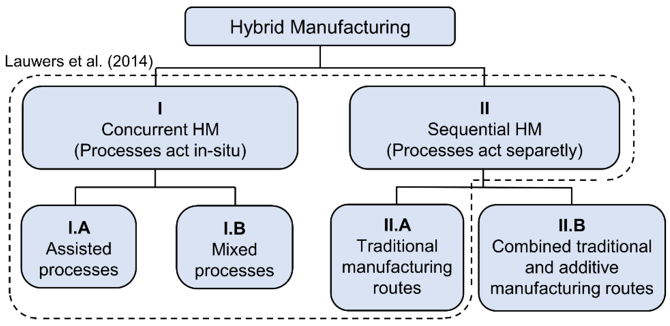
1. Introduction
2. Materials and Methods
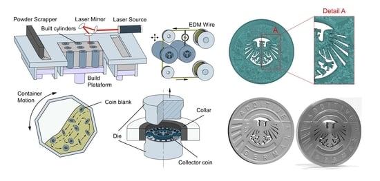
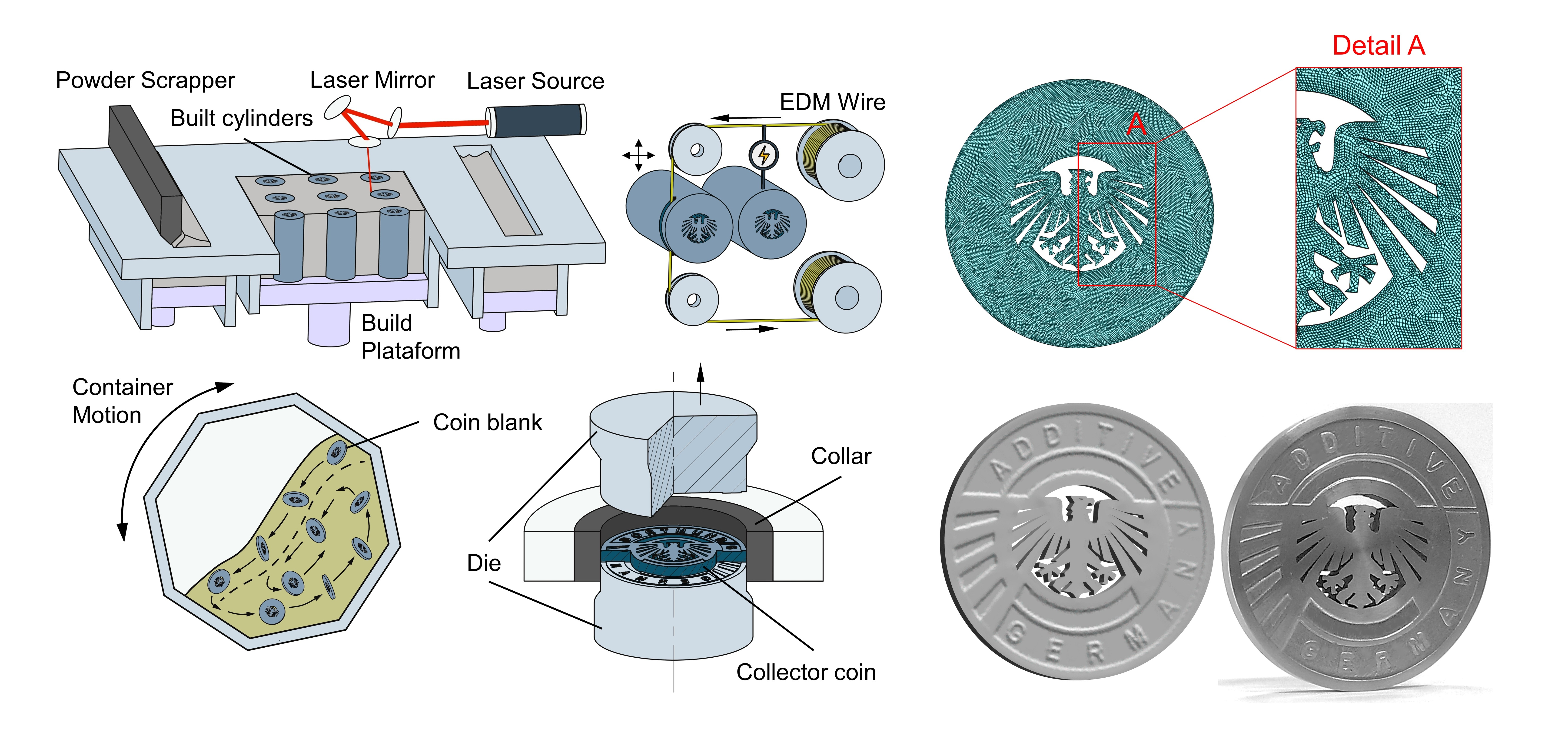
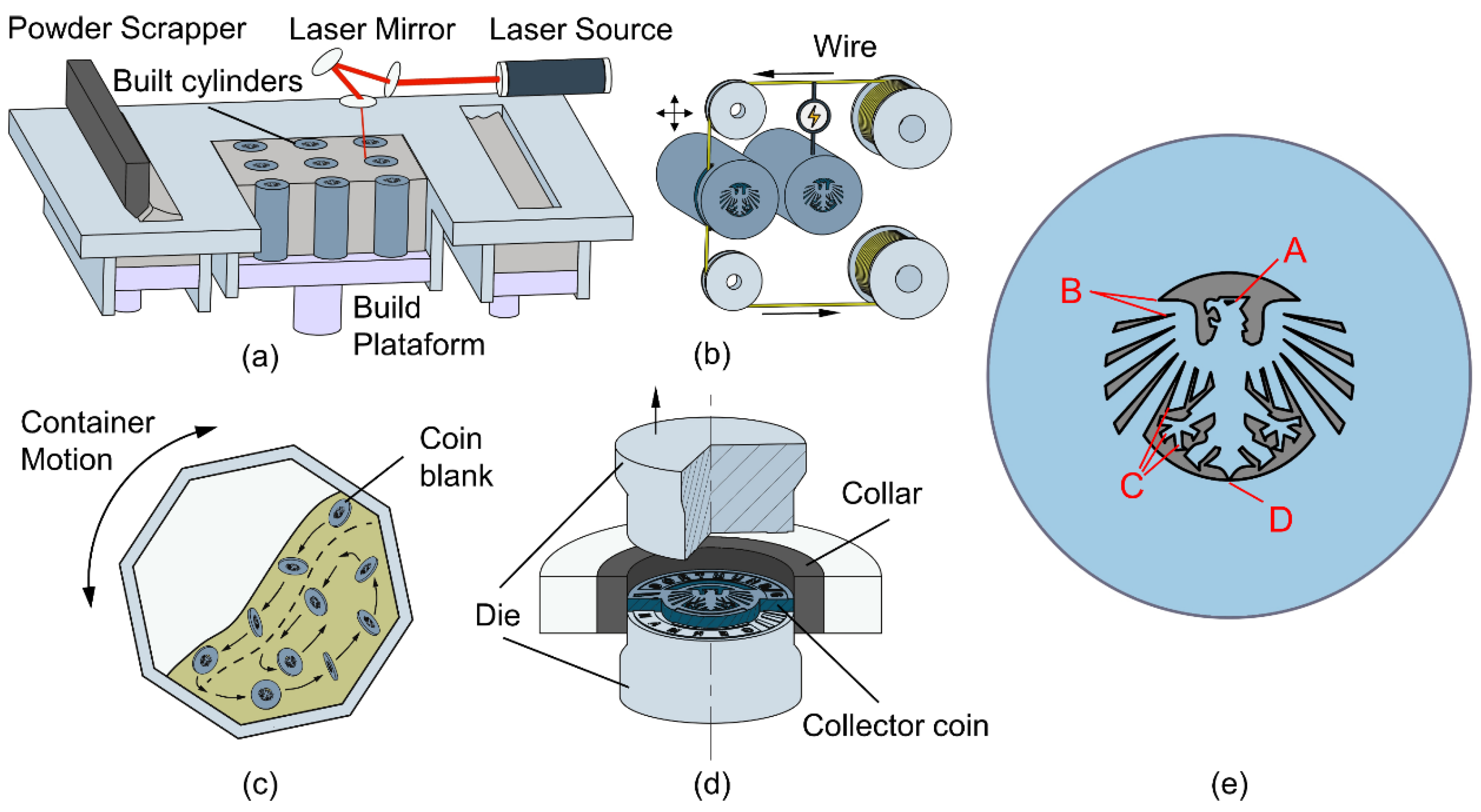
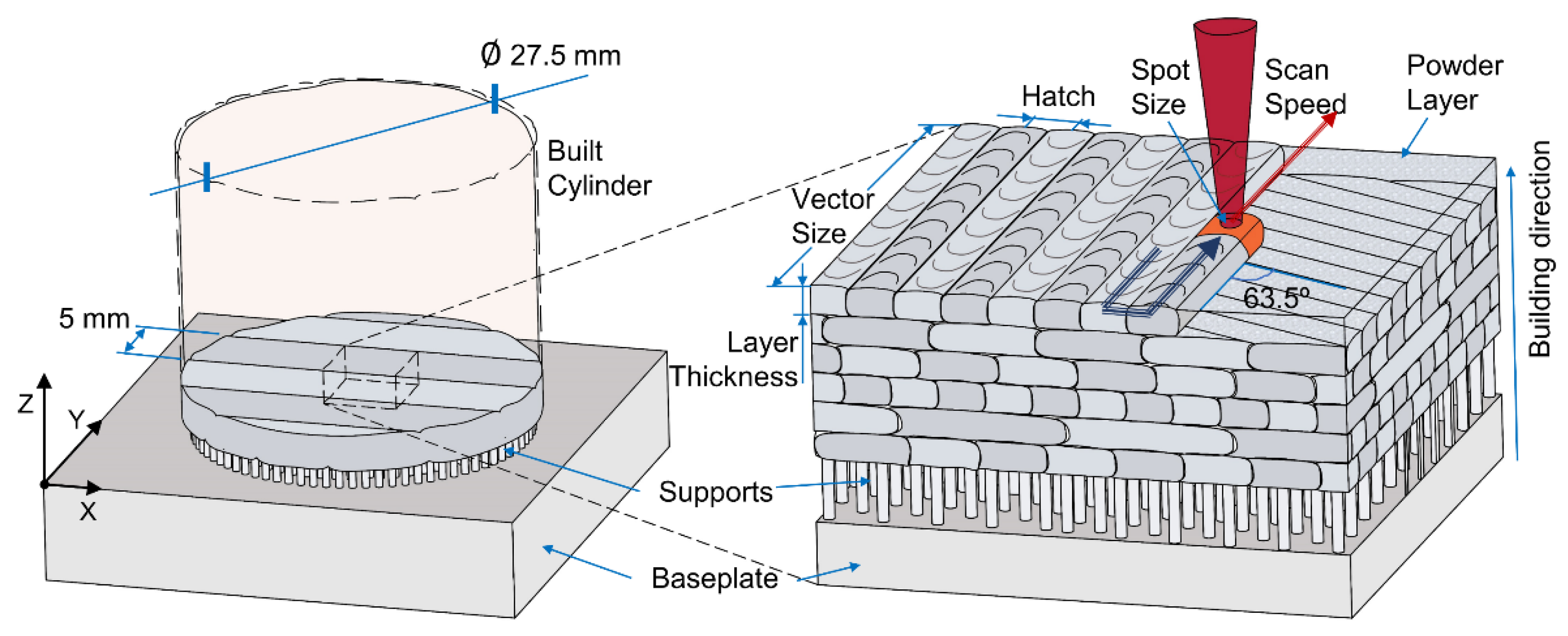
2.1. Additive Manufacturing
2.2. Testing Procedures
2.2.1. Relative Density
2.2.2. Flow Curve
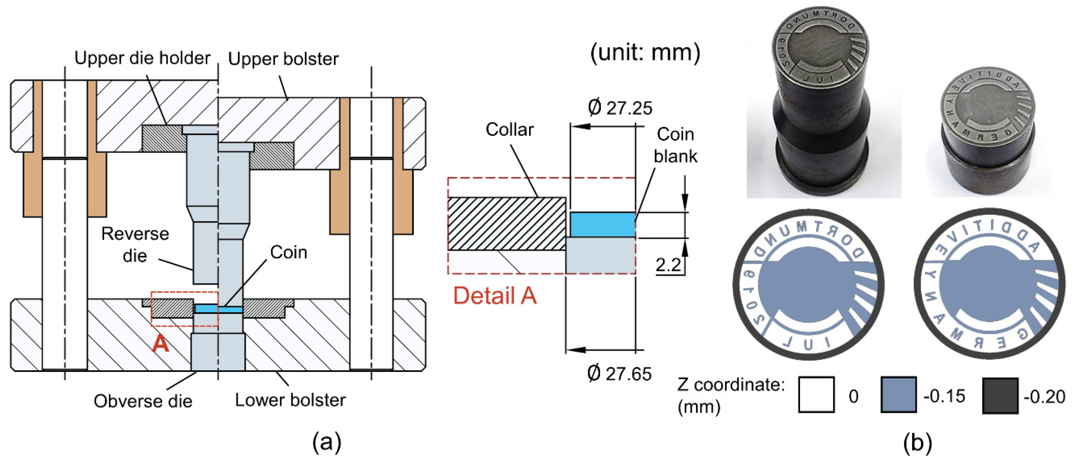
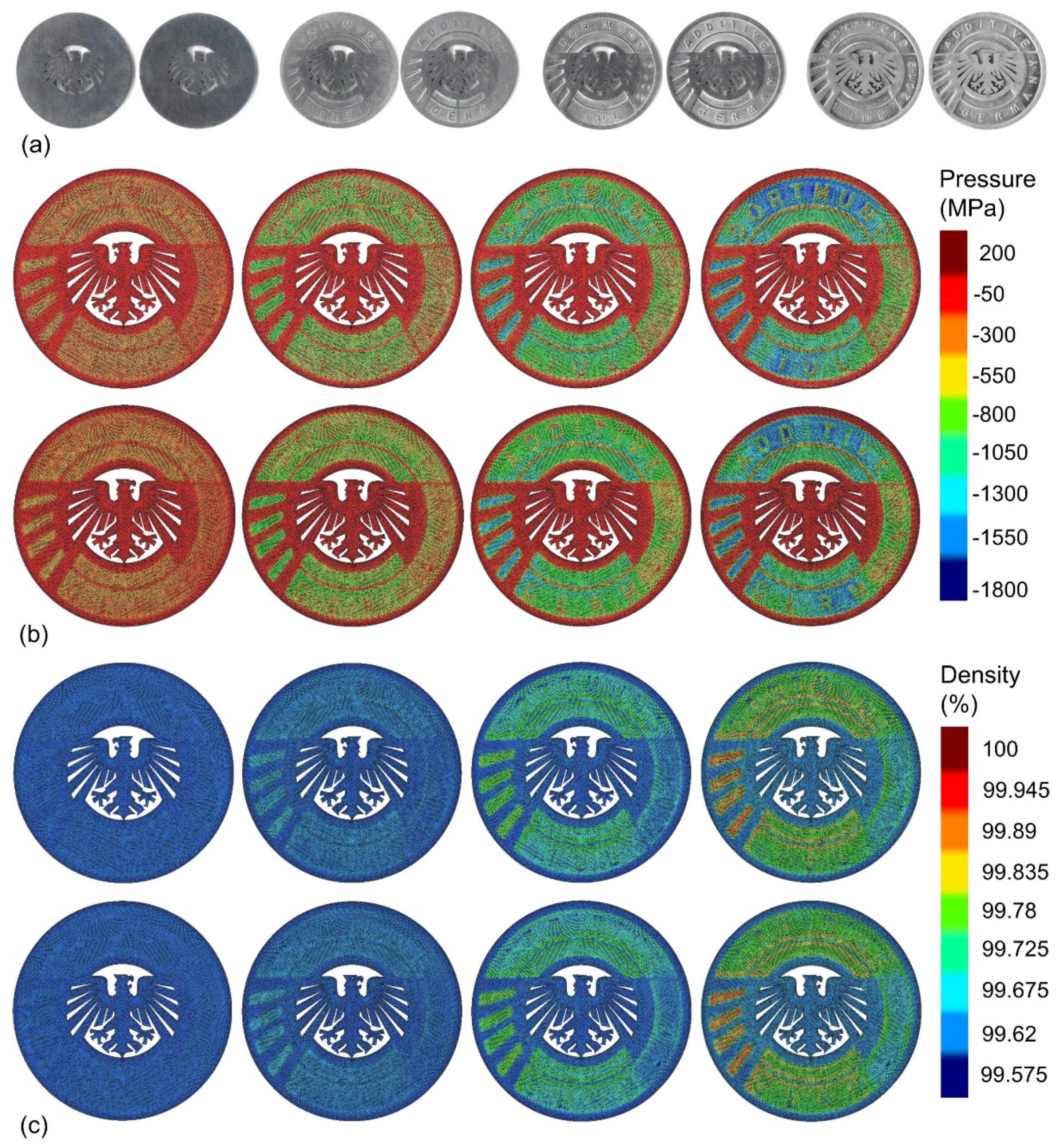
2.2.3. Coin Minting
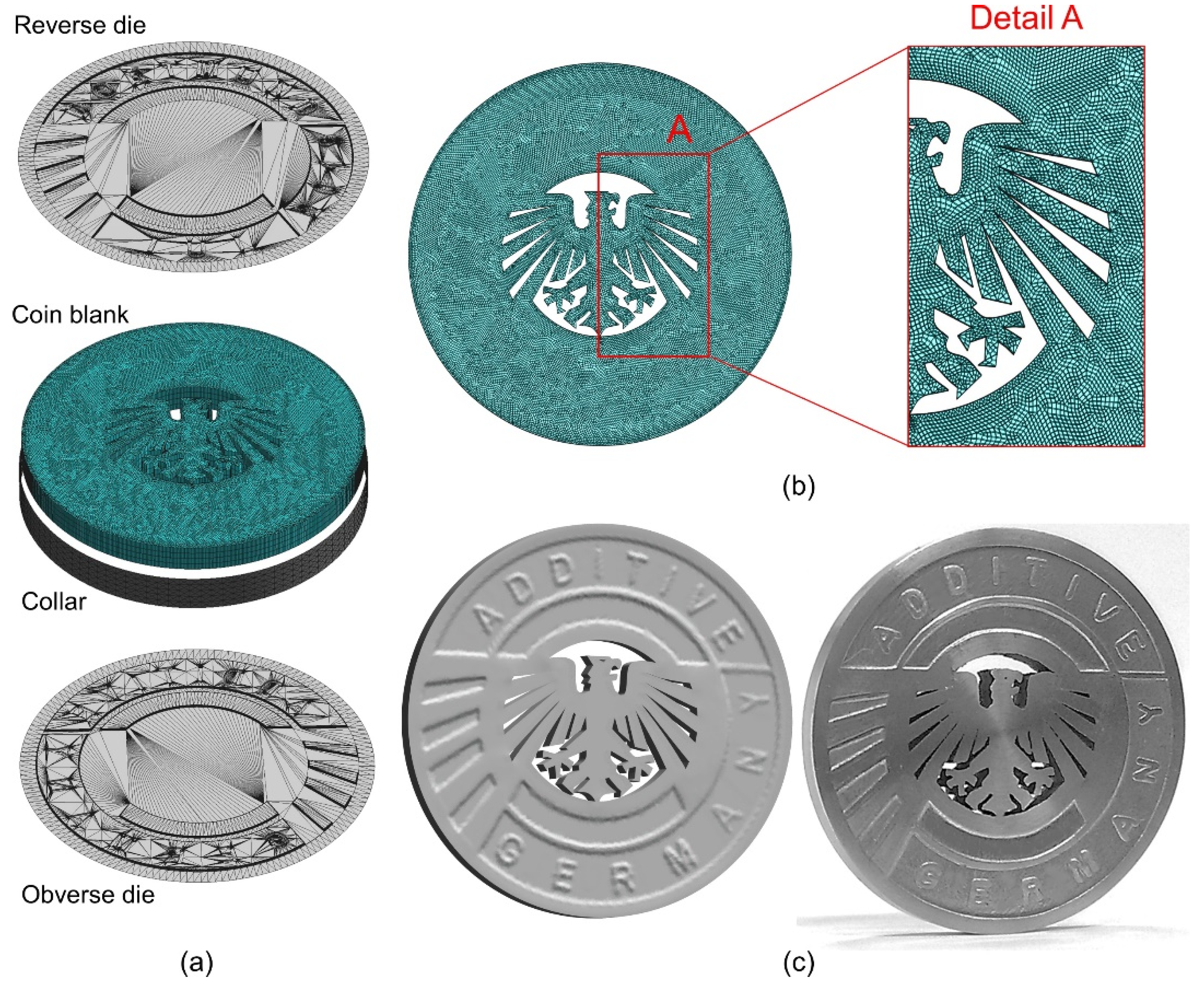
2.3. Numerical Modeling
3. Results and Discussion
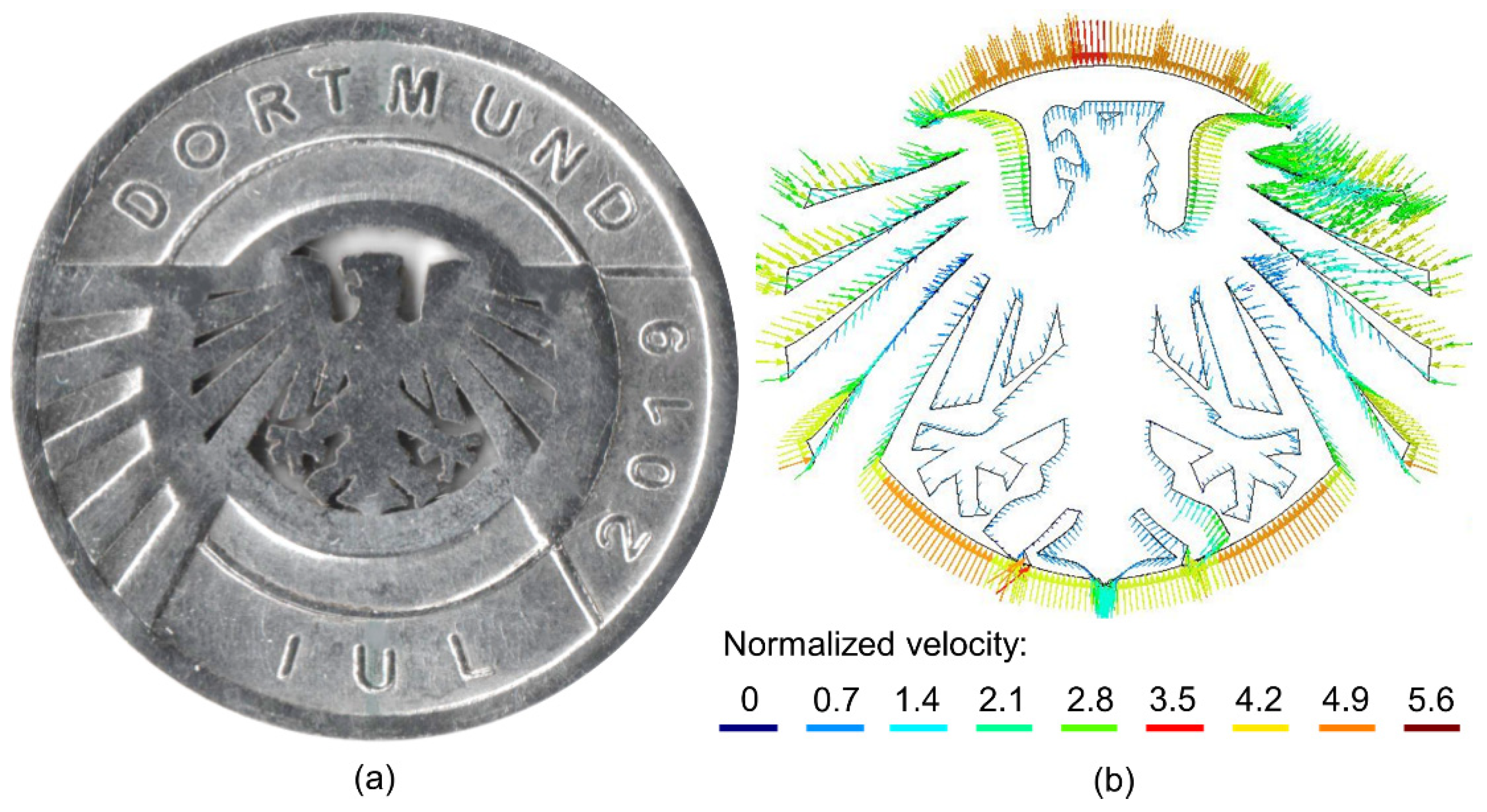
3.1. Material Flow
3.2. Eccentricity of the Vertical Force Resultant
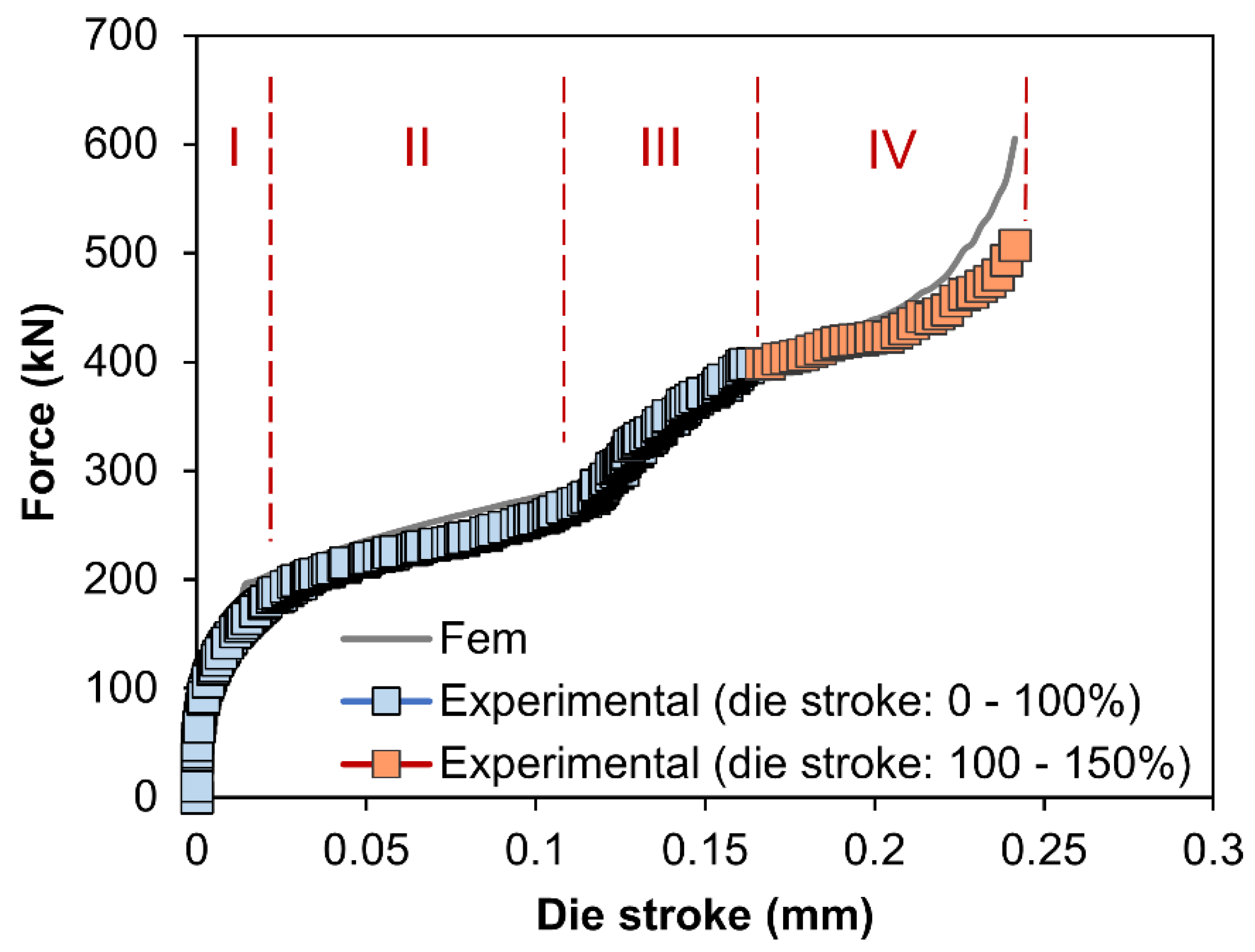
3.3. Force vs. Die Stroke Evolution
4. Conclusions
Author Contributions
Funding
Conflicts of Interest
References
- Lauwers, B.; Klocke, F.; Klink, A.; Tekkaya, A.E.; Neugebauer, R.; Mcintosh, D. Hybrid processes in manufacturing. Cirp Ann. Manuf. Technol. 2013, 63, 561–583. [Google Scholar] [CrossRef]
- Pragana, J.P.M.; Sampaio, R.F.V.; Bragança, I.M.F.; Silva, C.M.A.; Martins, P.A.F. Hybrid metal additive manufacturing: A state-of-the-art review. Adv. Ind. Manuf. Eng. 2020. under review. [Google Scholar]
- Fessler, J.R.; Merz, R.; Nickel, A.H.; Prinz, F.B.; Weiss, L.E. Laser Deposition of Metals for Shape Deposition Manufacturing. 1996 International Solid Freeform Fabrication Symposium. 1996. Available online: http://hdl.handle.net/2152/69928 (accessed on 5 December 2020).
- Klocke, F.; Wirtz, H.; Meiners, W. Direct Manufacturing of Metal Prototypes and Prototype Tools. 1996 International Solid Freeform Fabrication Symposium. 1996. Available online: http://hdl.handle.net/2152/69931 (accessed on 5 December 2020).
- Hölker, R.; Jäger, A.; Ben Khalifa, N.; Tekkaya, A.E. Process and Apparatus for the Combined Manufacturing of Workpieces by Incremental Sheet Metal Forming and Manufacturing Methods in One Set-Up. German Patent DE 10,201414202.7, 2014. [Google Scholar]
- Hafenecker, J.; Papke, T.; Huber, F.; Schmidt, M.; Merklein, M. Modelling of hybrid parts made of Ti-6Al-4V sheets and additive manufactured structures. In Production at the Leading Edge of Technology; Behrens, B.-A., Brosius, A., Hintze, W., Ihlenfeldt, S., Wulfsberg, J.P., Eds.; Springer: Berlin/Heidelberg, Germany, 2020; pp. 13–22. [Google Scholar] [CrossRef]
- Silva, C.M.A.; Bragança, I.M.F.; Cabrita, A.; Quintino, L.; Martins, P.A.F. Formability of a wire arc deposited aluminium alloy. J. Braz. Soc. Mech. Sci. Eng. 2017, 39, 4059–4068. [Google Scholar] [CrossRef]
- Sizova, I.; Bambach, M. Hot workability and microstructure evolution of pre-forms for forgings produced by additive manufacturing. Procedia Eng. 2017, 207, 1170–1175. [Google Scholar] [CrossRef]
- Pragana, J.P.M.; Cristino, V.A.; Bragança, I.M.F.; Silva, C.M.A.; Martins, P.A.F. Integration of forming operations on hybrid additive manufacturing systems based on fusion welding. Int. J. Precis. Eng. Manuf. Green Technol. 2019, 1–13. [Google Scholar] [CrossRef]
- Baptista, R.J.S.; Pragana, J.P.M.; Bragança, I.M.F.; Silva, C.M.A.; Alves, L.M.; Martins, P.A.F. Joining aluminium profiles to composite sheets by additive manufacturing and forming. J. Mater. Proc. Technol. 2020, 279, 116587. [Google Scholar] [CrossRef]
- Sokolov, P.; Aleshchenko, A.; Koshmin, A.; Cheverikin, V.; Petrovskiy, P.; Travyanov, A.; Sova, A. Effect of hot rolling on structure and mechanical properties of Ti-6Al-4V alloy parts produced by direct laser deposition. Int. J. Adv. Manuf. Technol. 2020, 107, 1595–1603. [Google Scholar] [CrossRef]
- Colegrove, P.A.; Coules, H.E.; Fairman, J.; Martina, F.; Kashoob, T.; Mamash, H.; Cozzolino, L.D. Microstructure and residual stress improvement in wire and arc additively manufactured parts through high-pressure rolling. J. Mater. Process. Technol. 2013, 213, 1782–1791. [Google Scholar] [CrossRef]
- Maamoun, A.H.; Elbestawi, M.A.; Veldhuis, S.C. Influence of shot peening on AlSi10Mg parts fabricated by additive manufacturing. J. Manuf. Mater. Process. 2018, 2, 40. [Google Scholar] [CrossRef]
- Rosenthal, S.; Platt, S.; Hoelker-Jaeger, R.; Soeren, G.; Kleszczynski, S.; Tekkaya, A.E.; Witt, G. Forming properties of additively manufactured monolithic Hastelloy X sheets. Mater. Sci. Eng. A 2019, 753, 300–316. [Google Scholar] [CrossRef]
- Hoelker, R.; Tekkaya, A.E. Advancements in the manufacturing of dies for hot aluminum extrusion with conformal cooling channels. Int. J. Adv. Manuf. Technol. 2015, 83, 1209–1220. [Google Scholar] [CrossRef]
- Barroqueiro, B.; Andrade-Campos, A.; Valente, R.A.F.; Neto, V. Metal additive manufacturing cycle in aerospace industry: A comprehensive review. J. Manuf. Mater. Process. 2019, 3, 52. [Google Scholar] [CrossRef]
- Moshiri, M.; Candeo, S.; Carmignato, S.; Mohanty, S.; Tosello, G. Benchmarking of laser powder bed fusion machines. J. Manuf. Mater. Process. 2019, 3, 85. [Google Scholar] [CrossRef]
- Xu, J.P.; Liu, Y.Q.; Li, S.Q.; Wu, S.C. Fast analysis system for embossing process simulation of commemorative coin–CoinForm. Comput. Model. Eng. Sci. 2008, 38, 201–215. [Google Scholar] [CrossRef]
- Alexandrino, P.; Leitao, P.J.; Alves, L.M.; Martins, P.A.F. Numerical and experimental analysis of coin minting. J. Mater. Des. Appl. 2019, 233, 842–849. [Google Scholar] [CrossRef]
- Pragana, J.P.M.; Rosenthal, S.; Alexandrino, P.; Araújo, A.; Bragança, I.M.F.; Silva, C.M.A.; Leitão, P.J.; Tekkaya, A.E.; Martins, P.A.F. Coin minting by additive manufacturing and forming. J. Eng. Manuf. 2020. [Google Scholar] [CrossRef]
- Alexandrino, P.; Leitão, P.J.; Alves, L.M.; Martins, P.A.F. Finite element design procedure for correcting the coining die profiles. Manuf. Rev. 2018, 5, 3. [Google Scholar] [CrossRef]
- Pragana, J.P.M.; Pombinha, P.; Duarte, V.R.; Rodrigues, T.A.; Oliveira, J.P.; Bragança, I.M.F.; Santos, T.G.; Miranda, R.M.; Coutinho, L.; Silva, C.M.A. Influence of processing parameters on the density of 316L stainless steel parts manufactured through laser powder bed fusion. J. Eng. Manuf. 2020, 234, 1246–1257. [Google Scholar] [CrossRef]
- Nielsen, C.V.; Zhang, W.; Alves, L.M.; Bay, N.; Martins, P.A.F. Coupled Finite Element Flow Formulation. In Modelling of Thermo-Electro-Mechanical Manufacturing Processes with Applications in Metal Forming and Resistance Welding; Springer: Berlin/Heidelberg, Germany, 2013. [Google Scholar] [CrossRef]
- Tekkaya, A.E.; Martins, P.A.F. Accuracy, reliability, and validity of finite element analysis in metal forming: A user’s perspective. Eng. Comput. 2009, 26, 1026–1055. [Google Scholar] [CrossRef]
- Doraivelu, S.M.; Gegel, H.L.; Gunasekera, J.S.; Malas, J.C.; Morgan, J.T.; Thomas, J.F. A new yield function for compressible P/M materials. Int. J. Mech. Sci. 1984, 26, 527–535. [Google Scholar] [CrossRef]


| Laser Power (W) | Spot Size (µm) | Scan Speed (mm/s) | Layer Thickness (µm) | Hatch Spacing (µm) | Vector Size (mm) | Shielding Gas |
|---|---|---|---|---|---|---|
| 250 | 100 | 750 | 50 | 100 | 5 | Argon |
| Wrought Blank | HAM Blank | HAM Coin | |
|---|---|---|---|
| Density (g/cm3) | 7967 | 7937 | 7953 |
| Relative density | 1 | 0.996 | 0.998 |
Publisher’s Note: MDPI stays neutral with regard to jurisdictional claims in published maps and institutional affiliations. |
© 2020 by the authors. Licensee MDPI, Basel, Switzerland. This article is an open access article distributed under the terms and conditions of the Creative Commons Attribution (CC BY) license (http://creativecommons.org/licenses/by/4.0/).
Share and Cite
Pragana, J.P.M.; Rosenthal, S.; Bragança, I.M.F.; Silva, C.M.A.; Tekkaya, A.E.; Martins, P.A.F. Hybrid Additive Manufacturing of Collector Coins. J. Manuf. Mater. Process. 2020, 4, 115. https://doi.org/10.3390/jmmp4040115
Pragana JPM, Rosenthal S, Bragança IMF, Silva CMA, Tekkaya AE, Martins PAF. Hybrid Additive Manufacturing of Collector Coins. Journal of Manufacturing and Materials Processing. 2020; 4(4):115. https://doi.org/10.3390/jmmp4040115
Chicago/Turabian StylePragana, João P. M., Stephan Rosenthal, Ivo M. F. Bragança, Carlos M. A. Silva, A. Erman Tekkaya, and Paulo A. F. Martins. 2020. "Hybrid Additive Manufacturing of Collector Coins" Journal of Manufacturing and Materials Processing 4, no. 4: 115. https://doi.org/10.3390/jmmp4040115
APA StylePragana, J. P. M., Rosenthal, S., Bragança, I. M. F., Silva, C. M. A., Tekkaya, A. E., & Martins, P. A. F. (2020). Hybrid Additive Manufacturing of Collector Coins. Journal of Manufacturing and Materials Processing, 4(4), 115. https://doi.org/10.3390/jmmp4040115