Article

Suppression of Polycrystalline Diamond Tool Wear with Mechanochemical Effects in Micromachining of Ferrous Metal

1
Department of Mechanical Engineering, National University of Singapore, 9 Engineering Drive 1, Singapore 117575, Singapore
2
School of Dental Technology, College of Oral Medicine, Taipei Medical University, Taipei City 110, Taiwan
3
Research Center for Biomedical Devices, Taipei Medical University, Taipei City 110, Taiwan
*
Author to whom correspondence should be addressed.
J. Manuf. Mater. Process. 2020, 4(3), 81; https://doi.org/10.3390/jmmp4030081
Submission received: 10 July 2020 / Revised: 24 July 2020 / Accepted: 6 August 2020 / Published: 11 August 2020
(This article belongs to the Special Issue Progress in Precision Machining)

Abstract

:
A mechanochemical effect is investigated to reduce diamond tool wear by means of applying a surfactant to low-carbon magnetic iron during diamond turning. Orthogonal microcutting demonstrates the manifestation of the mechanochemical effect through the reduction of cutting forces by 30%, which supports the notion of lower cutting temperatures for reduced tribo-chemical wear. This is affirmed by the reduction in tool flank wear by up to 56% with the mechanochemical effect during diamond turning. While wear suppression increases by 9.4–16.15% with feeds from 5–20 μm/rev, it is not proportional to the reduction in cutting forces (31–39.8%), which suggests that the reduction in cutting energy does not directly correspond with the reduction in heat energy to sustain tribo-chemical tool wear. The strain localization during chip formation is proposed to serve as a heat source that hinders the wear mitigation efficiency. Finite element simulations demonstrate the heat generation during strain localization under the mechanochemical effect, which counteracts the reduced heat conversion from the plastic deformation and the transfer from tool–chip contact. Hence, this paper demonstrates the effectiveness of the mechanochemical method and its ability to reduce tool wear, but also establishes its limitations due to its inherent nature for heat generation.

1. Introduction

Diamond is one of the hardest materials on the Earth with excellent thermal conductivity, low thermal expansion and a low coefficient of friction, which makes it one of the most ideal cutting tool materials [1]. Presently, there is a strong demand in diamond turning for precision products in the aerospace, semiconductor and biomedical industries [2]. The wide variety of tool geometries of diamond tools available allows the fabrication of complex shaped components with excellent surface finish such as Fresnel lenses and aspherical surfaces [3]. Materials such as aluminum, copper, silver and gold are termed “diamond-turnable” in view of the possibility to be machined over long distances without causing significant tool damage [4,5]. On the other hand, ferrous metals have been often reported to possess a high chemical affinity with carbon, which leads to excessive diamond tool wear during machining [6]. Steels are the most commonly used metals due to the low costs, high strength and good machinability properties. The 316L stainless steel is one of the choice materials used in artificial implant applications due to its corrosion resistance and biocompatibility properties [7,8]. Hardened steels used in the molding industry require mirror finishing and complex geometries that precision machining is capable of achieving at high productivity rates [9]. The increasing need for the durable ferrous metal used in the manufacturing of optics encourages the research on innovative methods to improve the diamond tool life in cutting steels.
Commendable efforts in various past achievements must be acknowleged in identifying the root causes and proposing innovations to suppressing diamond tool wear when cutting ferrous metals. In diamond turning, tribo-chemical wear occurs at an accelerated rate when the diamond and ferrous metal surfaces are in contact to initiate a chemical reaction based on the thermodynamics of carbon phase transition, where diamond is an unstable form of carbon and transforms into graphite under the right temperature and pressure conditions. One of the earliest theories leading to a greater understanding of the wear mechanism was introduced by Paul et al. [10] where a link was drawn between the severity of tool wear and the number of unpaired ‘d’ electrons of the metallic workpiece, such that the existence of unpaired electrons would suggest that the material element is not diamond-turnable. It has also been generalized that the surface layers of sp3 carbon of diamond restructure themselves into the powdery sp2 graphite form, in the presence of iron as a catalyst [11]. In other words, the interaction with a ferritic material acts as a catalyst to reduce the transition energy required for the stretching of C–C bonds that allows the restructuring of carbon atoms and eventually stabilizes in the graphite configuration [1]. Therefore, the root causes for reaction in tribo-chemical wear can be narrowed down to: (i) the interfacial temperature and (ii) the reactants involved.
In recent decades, several diamond tool wear mitigation techniques have been proposed to tackle the root causes as summarized in Table 1, which can be categorized into three main groups that either alter the machining environment, enhance the tool, or modify the work material. Multiple techniques have been shown to be highly successful at mitigating tool wear and producing optical-grade finishing, but the methods may have produced other undesirable implications on the final product surface.
Cryogenic turning can effectively reduce diamond tool wear by magnitudes of 10 after a cutting distance of 1000 m [13,14]. The retarded graphitization process enables the achievement of excellent surface finishing of <25 nm Ra [12]. However, how the intensely low-temperature machining environments affect the mechanical properties of the produced component has not been established. Ultrasonic elliptical vibration assisted machining (UEVAM) is also an effective wear reduction technique [19], which becomes particularly idealistic when coupled with the supply of oxygen into the cutting zone, to form oxide layers that serve as barriers between the cutting tool and workpiece [20]. However, oxide films will exhibit different mechanical responses to applied stresses such as the change in near-surface dislocation mobility [21].
While protective coatings [13] and the ion doping [17,18] of the cutting tool may not have any or present any obvious implications on the machined surface, each of these methods have their unappealing downsides. The coating method is still susceptible to abrasive wear, which would eventually leave the diamond tool exposed to chemical wear. In addition, the protective layer increases the effective tool edge radius, which gives up the unique advantage of a single crystal diamond cutting tool with a nanometric edge radii. The success of the ion implantation method is still questionable with a generally positive wear reduction outcome and few reports on higher wear rates when using doped tools [13].
The intentional alteration of work material composition has also showcased the reduction in diamond wear, such as the increase in carbon content [22] and the nitriding of steels [13]. Strictly speaking, this methodology bypasses the diamond tool wear problem by replacing the work material with a de facto surface-modified sample, rather than solving the problem directly. Recently, a rise in research activity on the benefits of a mechanochemical effect in machining can be observed, where the mechanical properties of the workpiece surface is temporarily altered under the influence of a surfactant [23]. To date, there have been no reports on the mechanochemical effect as a workpiece modification technique to suppress diamond tool wear when cutting ferrous metals. Thus, the aim of this paper is to explore this method as an alternative technique to mitigate diamond tool wear without adversely altering the machined surface.

2. Mechanochemical Effect

The phenomenon to temporarily alter the material properties has been realized through the chemical interaction (chemisorption) of a surfactant on a metal surface. The adsorption of surface-active media (SAM) was believed to reduce the surface energy of a material, which resulted in the embrittlement or enhanced plasticity in a solid [24]. This effect, named after its discoverer P.A. Rehbinder [25] as the “Rehbinder effect”, inadvertently influences the machining process by altering the plastic deformation during chip formation. Chaudhari et al. [26] applied marker ink in the microcutting process of copper and aluminum and saw a reduction in machining forces by 50% and 30%, respectively. Together with the reduction in cutting forces, thinner chips with reduced plastic deformation were observed when machining the surfactant-applied metal surfaces. Udupa et al. [27] also witnessed the transition from sinuous chip flow to a segmentation type with fractures on the free surface during the orthogonal mesoscale cutting of copper with glue as the SAM.
Under normal microcutting circumstances, the work material grains were presumably forced to shear by slip deformation toward the free surface of the chip resulting in a sinuous flow of repeated folds on the free surface of the chip [28]. Each of these folds was a result of the individual grains being deformed by slip toward the free surface where dislocations were allowed to “escape”. Naturally, higher stresses were expected to support the excessive plastic deformation of the chip. However, the presence of surface-active media on the free surface was believed to alter the workpiece surface properties and restrict the dislocation movement at the surfactant–workpiece interface [29]. It was assumed that the pile-up led to high stress concentrations and eventual brittle failure on the free surface of the chip, in contrast to the conventional folding of the chips by plastic deformation. Rehbinder’s theory [25] for fracture toughness, based on the well known Griffith’s formula for fracture stress (Equation (1)), predicted the lowering of material strength when the surface energy (γs) was reduced under the influence of a surface-active medium. Hence, the lower fracture criterion indicated that the reduction in stresses was required for crack propagation or an eventual brittle failure, which can be beneficial in metal-cutting processes through reduced energy consumption. The correlation between the fracture toughness and the effective cutting forces proposed by Atkins [30,31] was validated by Chaudhari et al. [26] to describe the expected reduction in cutting forces with lower fracture toughness:
K = c o n s t E γ s / a
where E is the Young’s modulus and a is the initial crack length. In theory, heat generation during machining should be reduced and the reduction in diamond tool wear can be expected with the reduction in plastic deformation during chip evolution and the lower cutting energy. However, this application has not yet been explored in tool wear investigations and it is the aim of this paper to shed light on the subject. Although the study of tool wear may appear to be rudimentary, the driving factors behind the tribo-chemical tool wear may also give new impetus to understand the mechanochemical effect. Moreover, this method showed the reversibility of the chemisorbed material properties upon removal of the SAM [24,26], which would reduce the adverse implications on the machined surface. Therefore, the mechanochemical effect on diamond tool wear was investigated through the application of surfactant on iron during diamond turning wear tests.

3. Experiments

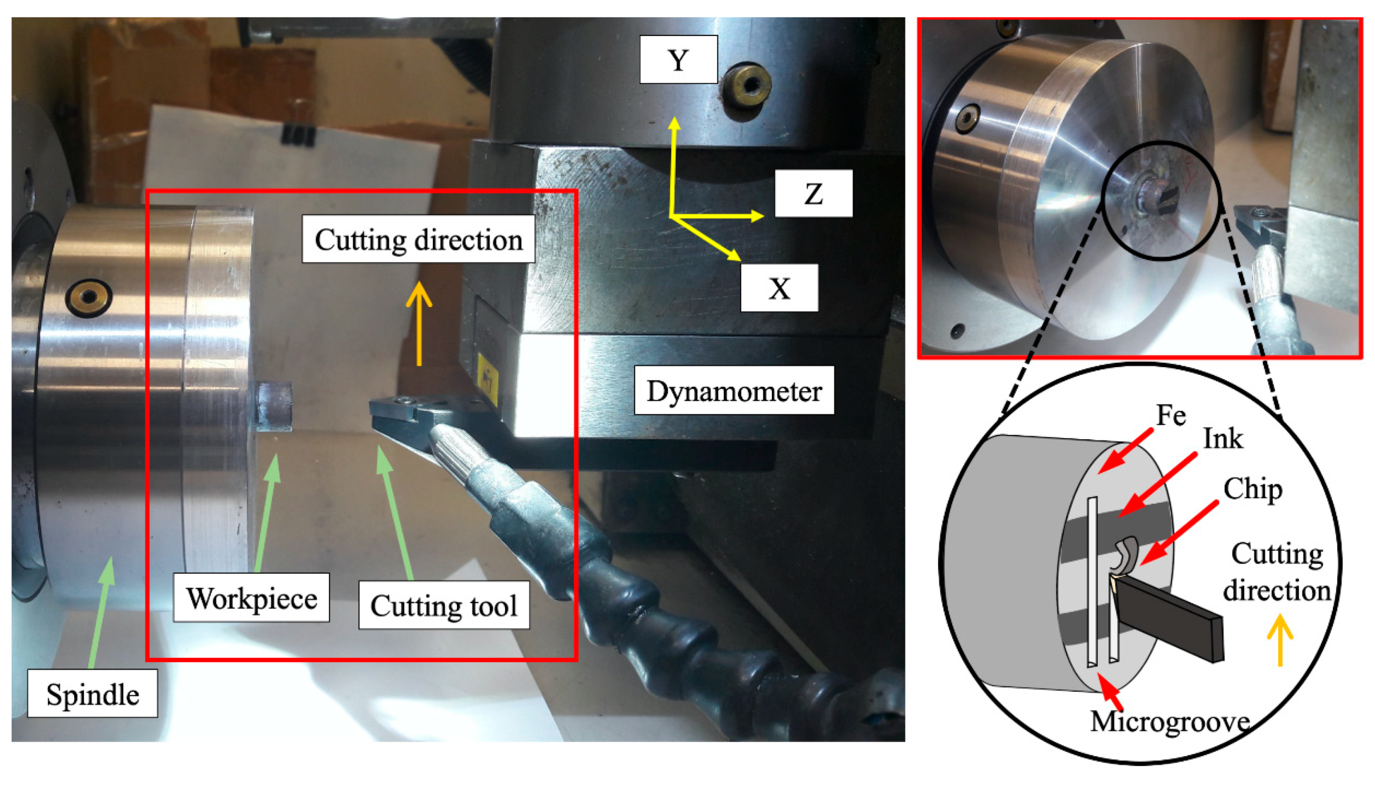
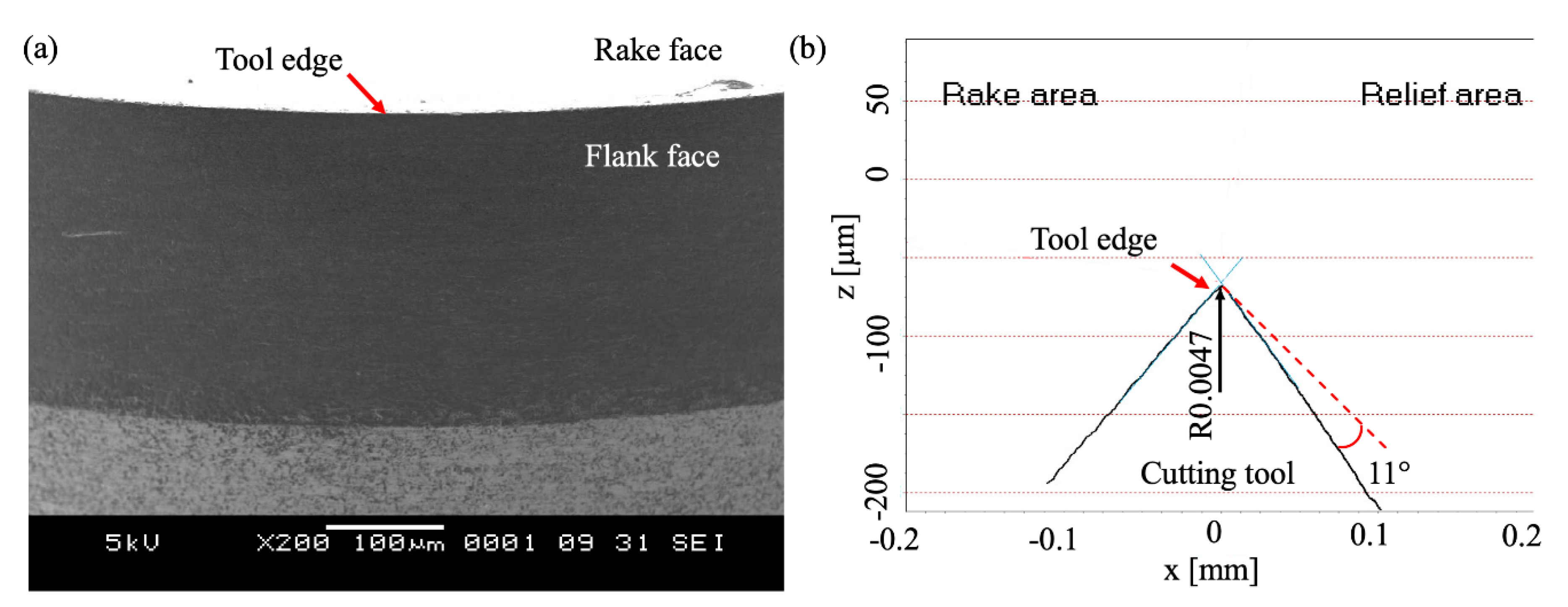
3.1. Mechanochemical Effect Validation

A series of experiments was conducted on low-carbon magnetic iron (ASTM-A848-01) procured from Kim Ann Engineering Pte. Ltd., Singapore, using an ULG-100 ultraprecision machining center manufactured by Toshiba Machine Co. Ltd., Shizuoka, Japan. The material composition is listed in Table 2. The influence of SAM on the work material was first verified through orthogonal microcutting tests, followed by the evaluation of diamond tool wear in diamond turning experiments. To ensure the flatness of the 12.7 mm-diameter sample surfaces before the start of each test phase, face trimming was performed using a 0.8 mm nose radius cubic boron nitride (CBN) cutting tool with a 0° rake angle and 7° clearance angle. The trimming feed was set at 15 µm/rev with a 2 µm nominal depth of cut. To verify the mechanochemical effect, two stripes (2 mm wide) stripes of Dykem High Purity marker ink (44404) were applied across the trimmed surface along the X direction. Subsequently, orthogonal microgrooves were conducted in perpendicular to the stripes at a constant cutting speed and depth of 50 mm/min and 12 µm as shown in Figure 1. Machining forces were measured using a Kistler 9256C1 dynamometer and type 5051A amplifiers with a sampling rate of 10 kHz. The cutting, thrust and lateral forces were oriented along the Y, Z, and X directions shown in Figure 1. Cutting chips were studied using a Jeol JSM-5500 scanning electron microscopy (SEM). The manifestation of the mechanochemical effect during orthogonal microcutting will be determined based on the reduction in cutting forces and the changes in chip morphology.

3.2. Diamond Turning Wear Tests

After validating the mechanochemical effect on the work material, two sets of face turning experiments were conducted with polycrystalline diamond (PCD) cutting tools to assess (i) the progression of wear over the cutting distance and (ii) the mechanochemical influence on the degree of wear. In face turning, the sample rotates along the Z axis at a constant spindle speed, while the cutting tool is fed into the workpiece with the nominal cutting depth along the Z-direction and at a constant feed rate along the X direction.
PCD tools with a 0.8 mm nose radius, 0° rake angle, and 11° clearance angle were used in the first set of wear tests (Figure 2a). The tool edge radius was measured to be 4.7 µm using a MikroCAD 3D optical imaging system as shown in Figure 2b. The test parameters were controlled at 600 rpm rotational speed, 9 mm/min feed rate and 2 µm nominal depth of cut. All experiments were completed under dry conditions to avoid the secondary effects of cutting fluids such as cooling and lubrication [32]. A set of tests was performed without the ink to serve as a reference. The cutting tool wear land was measured using optical imaging after each turning pass, following which, a new workpiece and cutting tool were used to evaluate the wear progression with the application of SAM. Optical imaging and the measurement of wear lands were captured using a Leica DM2500 M optical microscope. The ink was fully applied onto the work material surface in between each turning pass. Similarly, the wear land of the cutting tool was measured using the optical microscope after each turning pass and the machined surface roughness measurement was conducted using a Taylor Hobson Form Talysurf-120 profiler at the end of the diamond wear tests.
The second set of diamond tool wear tests were performed on the iron workpiece using PCD tools with a 0.4 mm nose radius. The diamond turning parameters were kept constant at 600 rpm spindle speed and 2 µm nominal depth of cut, while the feed rate was varied over 3, 6, and 12 mm/min, to achieve effective feeds of 5, 10 and 20 μm/rev, respectively. Diamond turning was performed continuously over a fixed cutting distance of 50.4 m, for both conventional turning and cutting with the mechanochemical effect for comparison. Dykem ink was reapplied to the workpiece surface prior to each trimming pass.

3.3. Surface Microhardness Tests

The Vickers microhardness test was employed to understand the implications of the surfactant on the surface mechanical properties. A Shimadzu HMV-2 microhardness test setup was used to apply indentation loads of 1.0 N with a dwell time of 15 s. Three indentations were tested on the iron surface, a surface adsorbed with Dykem ink, the iron surface after removing the surfactant with ethanol, and an iron surface after wiping with ethanol. The latter was necessary to validate the temporal effects of surface adsorbed by Dykem ink.

4. Experimental Results

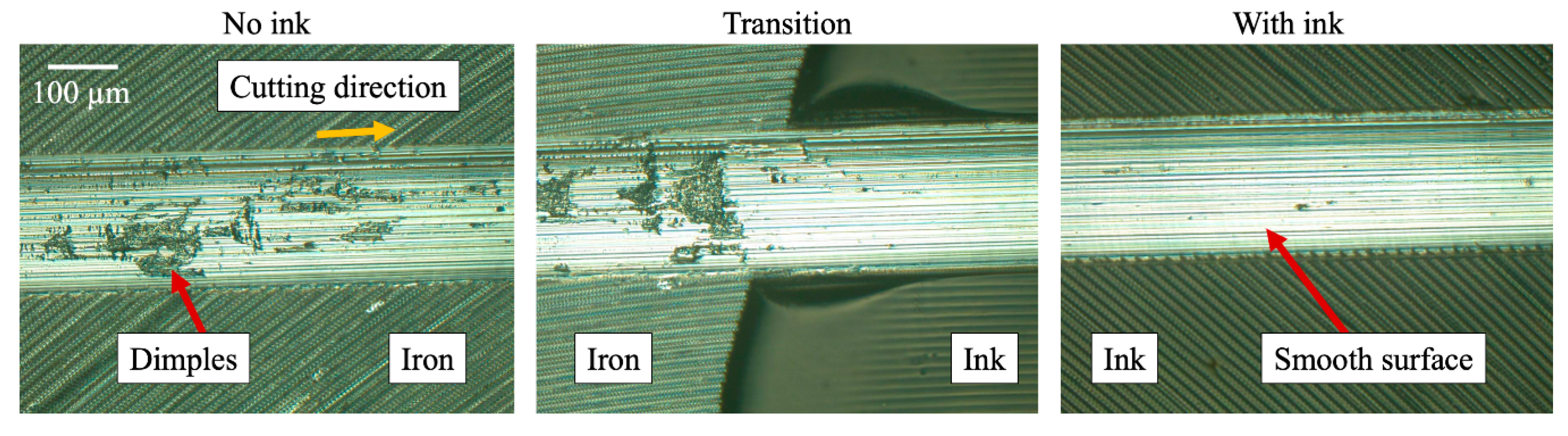
4.1. Validation of Workpiece Modification

Cutting force observation is an effective method to verify the influence of SAM on a work material. Figure 3a shows the drastic reduction in cutting force by approximately 30% when the tool removes the surface-affected layer, and correspondingly produces thinner deformed chips (Figure 3b) during orthogonal microcutting. Figure 3c shows a top view of the chip formation from the orthogonal microcutting tests on iron with variations in chip morphology according to the order of surface-active media-affected sections. It is evident that the thicker chips exhibit multiple folds that are attributed to the plastic deformation of the chip, while an immediate change occurs from the mushroom-like features for the unaltered surface to the sharp edges for the surfactant-affected segments. This can be attributed to the embrittlement of the chips as a result of the reduction in plastic deformation (i.e., brittle failure of the chips) under the influence of the surface-active medium [33].
Although not commonly reported, the mechanochemical effect also improves the machined surface quality [23]. A sharp distinction in machined surface topography can be observed between that produced with and without SAM, as shown in Figure 4. Unique surface defects in the form of dimples are prominent in the regions without ink, which is similar to the observations in the micromachining of AISI 1045 steel [34]. In microcutting, considerations for material deformation characteristics of individual grains must be adopted, such that plastic deformation occurs by shearing along the slip planes of the grain crystallographic orientation. The randomly oriented grains then result in changes to the material removal process such as the deformation features in the chips [35] and the machined surface [36]. The misalignment of shearing forces for favourable slip deformation would result in machined surface defects [36], taking the form of the dimples observed in Figure 4. On the contrary, smooth defect-free machined surfaces can be produced with the application of ink, which suggests that the shearing action occurs with ease along the slip system under the mechanochemical effect. It is good to note that the transition to a smoother machined surface is not dependent on the coating thickness, which rules out the mechanical implications of the ink as a solidified coating that was observed by Lee et al. [37] during the micromachining of brittle materials. The observations of the characteristic features of the Rehbinder effect in machining [26,28] verify the effectiveness of the mechanochemical effect on the iron workpiece and serve as the fundamental mechanism to explain the differences in diamond tool wear.

4.2. Diamond Tool Wear

Significant tool wear can be observed on the flank face of all cutting tools after the diamond turning of iron over a cutting distance of 58.8 m. The wear patterns show vertical streaks perpendicular to the cutting edge, which is a characteristic feature for chemical tool wear on diamond tools. Although chemical wear is inevitable due to the high chemical affinity between the workpiece and diamond, the wear land is reduced under the mechanochemical effect as shown by the wear progression in Figure 5a.
The wear progression of the tool under conventional cutting conditions presents the typical flank wear development plot where rapid wear initially occurs within a short time, followed by a stable progression and finally ending off with an acceleration before failure. The increased rate of wear under conventional cutting occurs as the cutting distance goes beyond 42 m. In contrast, the wear development under the mechanochemical effect remains as a gentle inclined gradient, which indicates that the tool has not reached the critical stage before failure. The wear land, defined by the maximum height of the wear marks (VBmax), is lower by 56% under the Rehbinder effect. Naturally, the lower tool wear led to a 27% improvement in the final surface roughness of 41.8 nm Ra as compared to 57.2 nm Ra under normal conditions (Figure 5b). The produced surface roughness is dependent on the cutting tool geometry (i.e., wear morphology) and tool-tip vibrations induced by the material microstructure characteristics [38]. Hence, the disparities in surface roughness are determined to be caused by the differences in tool profile as a result of tool wear and the enhanced material removal mechanism that reduces tool-tip vibrations.
The second set of tool wear tests, using 0.4 mm nose-radius cutting tools, demonstrates the magnitude of the mechanochemical effect on tool wear at different feed rates as shown in Figure 6. Although the overall cutting distance for each cutting parameter was the same, the wear lands are drastically different with increasingly devastating wear at higher feeds regardless of any mechanochemical influence. This is due to the effectively larger volume of the engaged material that increases the cutting forces during machining as shown in Figure 7, and translates to the overall heat generation that leads to tribo-chemical wear. Moreover, the cutting forces increase over time due to the degradation of the cutting edge geometry that results in the instabilities of the machining process, such as vibrations and the irregular build-up of work materials.
The machined surface is also presented for each cutting condition by pictorally examining the optical quality of the surface. Extremely poor surface conditions at a small feed of 5 μm/rev are observed before achieving near-mirror finishing at higher feed rates. This can be attributed to the relative tool sharpness size effect, which invokes rubbing as the material deformation process when the tool edge radius is significantly larger than the effective uncut chip thickness [39]. Although it would be interesting to investigate further the correlation between the mechanochemical effect and the material removal mechanism, the topic is out of the scope of this paper, which focuses on the mechanochemical influence on diamond tool wear.
At higher feeds of 10 and 20 μm/rev, where shearing is the material removal mechanism, the reflected images appear to be clearer under the mechanochemical effect when compared with the surfaces produced by conventional cutting. In addition to the enhanced surface quality expected under the mechanochemical influence (Figure 5), the clearer reflections are also results of the reduced wear lands. As the wear land increase, the machined surface quality is expected to deteriorate due to the degraded tool geometry that could change the material removal mechanism. Nonetheless, diamond tool wear is reduced, regardless of the material removal mechanism, with increasing feeds from 5 to 20 μm/rev, corresponding to magnitudes of 9.4%, 14.78%, and 16.15%. In the meantime, it is good to note that the difference in percentage wear reduction between the two different wear tests is in the size of the nose-radius, where wear rates are often higher for smaller nose-radii [40].
As the spindle revolution was kept constant throughout the tests with the 0.4 mm nose radii tools, the change in feed rate changes the feed per revolution, which determines (i) the effective area of the uncut chip thickness during turning and (ii) the surfactant-affected length as shown in Figure 8. These are two main factors that define the degree of influence that the mechanochemical effect has on the material response. The effective uncut chip thickness corresponds to the degree of plastic deformation during material removal, which would affect the performance of the mechanochemical effect. It was suggested that the physicochemical phenomenon is even more effective to cause embrittlement when dealing with ‘gummy’ metals that exhibit high plasticity during deformation and are challenging to cleanly cut [27]. Therefore, a thicker uncut chip thickness that should correspond to a higher degree of plasticity in the chips would call for a more significant influence of the mechanochemical effect. The geometrical aspects between the feed and the effective uncut chip thickness have been covered in detail by Chaudhari and Wang [29] and the principals may be applied to explain the different magnitude of tool wear reduction under the mechanochemical effect. In general, the increase in feed enlarges the effective uncut chip thickness and therefore improves the effectiveness of the mechanochemical effect due to the increase in plastic deformation.
The effective coverage of the surfactant during turning is directly proportional to the feed, such that larger feeds would encounter larger volumes of surfactant-affected material that would influence the manifestation of the Rehbinder effect. However, it is also important to consider the proportion of surfactant-affected material to the main bulk of material that is not covered with ink. Figure 9 illustrates the influence of feed and nominal cutting depth on the proportions of surface lengths that are under the mechanochemical effect. During turning, the length of surfactant-affected material is equivalent to the feed (f) and the length of unaffected material p when cutting with a round-nosed tool can be determined by Equation (A3) in Appendix A. The surfactant coverage can then be calculated by Equation (2):
η = f f + p %
The percentage increase in surfactant coverage shows an increasing trend with a larger feed, similar to the trend observed in the reduction of cutting forces during the experimental wear test. This verifies the increasing influence of the mechanochemical effect with larger feeds. Curiously, the percentage reduction in wear does not directly coincide with the reduction in cutting forces and the influence of surfactant coverage. While other factors such as the tool-tip vibrations and the tribo-chemical nature of diamond tools may also participate in the wear progression, these factors should not affect the results to this degree. This intriguing question will be answered as the mechanism of the mechanochemical effect on tool wear is progressively discussed in the subsequent sections.
In the meantime, it may appear that larger feeds should be used during machining to a ensure wider coverage of the material under the mechanochemical effect, but the use of larger feeds would increase the theoretical peak-to-valley height of the machined surface and incur larger machining forces as observed in Figure 7. Hence, it is suggestive to say that there exists an optimal balance between low feeds for better surface finishing and the proportion of surfactant-affected material, which can be achieved through a series of systematic controlled tests involving a large quantity of cutting tools.
While larger feeds may accommodate a larger proportion of surfactant-affected material, the nominal cutting depth also presents its significant influence on the proportion of surfactant coverage where the surfactant coverage increases as the cutting depth decreases. Herein lies a critical need to study the Rehbinder effect in micromachining due to the increasing influence of the mechanochemical effect as the cutting characteristic length decreases further into the microscale. To this end, the working principle of the mechanochemical effect on this work material must be evaluated before explaining the occurrence of wear reduction.

5. Discussion

Influence of the Surface-Active Medium

Microhardness tests show that the surfactant increases the surface hardness of the iron sample by 9.3% from 335.3 HV0.1 to 369.7 HV0.1. After removing the surfactant, the sample returns to its original hardness that averages 336.7 HV0.1. The reversion of microhardness presents a key characteristic of the mechanochemical effect, which is a highly beneficial factor of this methodology to reduce diamond tool wear without permanent modifications to the mechanical properties of the fabricated component. Moreover, it can be observed that the ethanol has a negligible influence on the material surface, which makes it a suitable solvent for this temporary workpiece modification process.
The increase in hardness may be explained by a sequence of events that involves the stresses for dislocation nucleation at the onset of plastic deformation, dislocation mobility and the pileup of dislocations. An ease in dislocation nucleation and emission within the adsorbed material can be ascribed to the increase in free electron concentrations and the corresponding decrease in local shear modulus [41]. Teus et al. [42] identified the similar phenomenon with surfactants on iron and explained that dislocation emission stresses in Equation (3) will be reduced with a corresponding increase in dislocation mobility, due to the reduced line tension in Equation (4). However, the enhanced dislocation activity would reduce the distance between the pile-up dislocations at grain boundaries, which would subsequently increase the shear stresses (τL) required for plastic deformation (Equation (5)), and congruently reflect a higher microhardness value with a smaller indentation marking:
τ 2 μ b / L
Γ [ μ b 2 4 π ] / log ( 5 b )
τ L = n τ = ( π μ b ) / [ 16 ( 1 υ ) d ]
where µ is the shear modulus, b is the burgers vector, L is the distance between pinning points, ℜ is the dislocation curvature radius, υ is the Poisson’s ratio, n is the number of dislocations, and d is the distance between dislocations.
The explanation for the increase in microhardness can also be adapted to elucidate the results observed in microcutting, beginning with the adsorbed chip-free surface that undergoes embrittlement due to the influence of the surfactant. Malkin [24] describes this phenomenon of free surface generation as a favourable energy system to break the interatomic bonds in the bulk material and form interatomic bonds with the surfactant. Lee and Wang [23] applied this concept to propose the sequence of events along the primary deformation zone that leads to the embrittlement process. As shown in Figure 10, the dislocation activity is enhanced from the surface under the Rehbinder effect, due to the breakage of interatomic bonds of the work material and crack formation. Subsequently, dislocation pile-up occurs when the dislocations of increased density entangle with those emitted from the tool tip to result in strain localization within the chip. It is important to emphasize that the crack formation shown in Figure 10 only serves as an illustration of a simple crack geometry during embrittlement, along the primary deformation zone, and does not exemplify the mode of crack formation. In reality, not only does the embrittlement process involve a tensile stress component for crack-opening (i.e., stress intensity factor Mode I), but also the typical shear stresses observed during cutting that induce crack-sliding (i.e., Mode II). Understandably, Griffith’s relation (Equation (1)) describes macroscopic crack formations, while the surfactant-workpiece interaction manifests on the molecular level. At this scale, surface forces become increasingly influential towards the fracture stress, which then invokes the atomistic relationships in Equations (3)–(5) to explain the embrittlement process. Although it is unnecessary for microcracks to be present on the pre-machined surface, high stress concentrations due to the pile-up of dislocations along the shear plane and the favourable energy conditions would cause the nucleation of cracks on the free surface of the chip [26]. On the other hand, pre-machined surface defects will enhance the chemisorption interactions with crack tips [24] as well as the surfactant–workpiece interaction at the molecular level.
Coincidentally, the described phenomenon resembles the sequence of events during the adiabatic shear band (ASB) formation, which is also speculated to initiate from the free surface of the chip [43]. ASBs are commonly formed during the machining of difficult-to-machine materials, in a competition between work hardening under deformation and catastrophic failure by abrupt thermal softening effects. However, the mechanochemical effect on chip formation differs from the conventional observations of ASB formation, in that the failure from the free surface of the chip occurs at a higher frequency compared to the visibly periodic saw-tooth chip formation associated with ASBs.
With the application of SAM prior to machining, the work material is affected at the free surface of the chip, which does not come in contact with the diamond tool. Hence, lubrication effects at the tool–chip interface are negligible, as also clearly demonstrated in orthogonal microcutting tests. Morevoer, the mechanochemical effect does not have a direct influence on the flank face where tool wear manifests, because the surfactant does not contact the machined surface. Following the common understanding of the two main factors leading to diamond tool wear during the machining of ferrous metals—temperature and catalytic material—any change in wear progression is improbable to be the direct result of the surface property alteration, but rather an effect of the change in heat generated at the tool–workpiece interface. The volumetric wear of diamond is understood to increase with the rise in temperature during thermal erosion tests, regardless of the workpiece composition [22]. Since the workpiece composition remains the same in this work, the reduced tool wear is likely a result of lower temperatures at the cutting zone.
Based on this premise, the significant mechanochemical influence on the machining forces may be used to explain its indirect impact on the heat generated in the cutting tool. The reduction in cutting forces would correspond to the reduction in overall heat generated from the three plastic deformation zones and friction at each contact interface shown in Figure 11 [44]. The reduction in the plastic deformation of the chips under the mechanochemical effect presents a direct proposition for the decline in work–heat energy conversion. In addition, the chip compression ratio (λ) determines the shear angle (ϕ), which corresponds to the tool–chip contact length, Lc, such that a thinner chip will reduce the contact length [45]. This is particularly important as the heat generation at the tool–chip interface is severely influenced by friction and thermal transfer from the primary and secondary shear process [46]. The thin chip segment with a large curvature in Figure 3b proves the propensity for reduced tool–chip contact lengths under the mechanochemical effect. The reduction in diamond cutting tool wear can therefore be attributed to the reduced heat generated by plastic deformation during chip formation, which lowers the rate of the tool–workpiece chemical reaction.
However, the severe strain localization in the primary deformation zone under the mechanochemical effect may also lead to substantial heat generation that hinders the effectiveness of the mechanochemical method to reduce diamond tool wear. This would explain the scaled-down improvements in tool wear resistance, when comparing to the magnitudes of reduction in cutting forces. Further analyses are necessary to investigate this possibility. Unfortunately, the measurement of cutting temperatures at the microscale is generally difficult to perform at this point, but conventional macroscopic theoretical models are capable of providing fundamental insights to the heat generated in the cutting zone.

6. Finite Element Analysis

Numerical analysis offers an approach to investigate the heat generated during chip formation, which was described to cause the catastrophic diamond tool wear when cutting ferrous metals. It is necessary to note that the simulation of diamond tool wear with finite element analysis (FEA) at the microscale has not been developed due to the mandatory participation of chemical interaction between the tool and the workpiece. Although FEA is capable of illustrating material failure, the limited time scale and extreme hardness of diamond make it impossible to accurately model diamond tool wear at this point in time. While interatomic potential considerations in molecular dynamics (MD) simulations could describe the chemical interaction during machining [47], the cutting length scale is limited to the nanometric range and is computationally too expensive to model microscopic deformation. Therefore, the FEA theoretical study in this paper was only aimed at studying the heat generation during the chip formation under the simulated mechanochemical phenomenon, with no considerations for the tool–workpiece chemical affinity.

6.1. Model Setup

The simulation was performed using commercially acquired software ABAQUS/Explicit with the in-built Johnson–Cook (J–C) material model [48]. The J–C constitutive model captures the material viscoplasticity during the deformation of metals under large strain, high strain rates and the influence of thermal softening. A 0° rake-angled cutting tool with an edge radius of 2 μm was modeled as a rigid surface to assume the strong mechanical properties of diamond. The cutting speed was set at 50 mm/min and the cutting depths were modeled as 10 μm. The two-dimensional workpiece was built with 10,253 CPE4R elements with an average mesh size of 0.5 μm. Specific cutting forces were determined by the cutting force per unit width of material removed.
During deformation, the material stress–strain response comprises three main stages as illustrated in Figure 12. The region a–b comprises the linear elastic region that is governed by Young’s modulus and the yield strength, before enduring plastic deformation with strain hardening effects in the region b–c. The equivalent plastic flow stress during elastic–plastic evolution is described by Equation (6). Upon reaching the maximum load-carrying capacity, the material strength degrades in the region c–d before its eventual failure. This region follows the damage initiation and evolution laws in the J–C shear failure model described in Equation (7). Initiation occurs when the scalar damage parameter in Equation (8) exceeds the nominal value of 1:
σ = [ A + B ε n ] [ 1 + C ln ( ε ˙ ε ˙ 0 ) ] [ 1 ( T T r T m T r ) m ]
ε D = [ D 1 + D 2 exp ( D 3 σ m σ ) [ 1 + D 4 ln ( ε ˙ / ε ˙ 0 ) ] [ 1 + D 5 ( T T r T m T r ) ] ]
ω =   ε ε D
where A is the yield stress, B is a strain hardening constant, n is the strain rate hardening parameter, C is the strain rate factor, and ε is the equivalent plastic strain. D1D5 are the failure parameters, σm is the mean stress, and ε ˙ 0 is the reference strain rate. As the J–C material parameters for ASTM-A848-01 have not been established, the material parameters of a well verified annealed aluminum alloy (AA6061-T6) were adopted to describe the differences in heat generated during microcutting with the mechaniochemical effect. This follows the established influence of the Rehbinder effect on AA6061-T6 [26]. The material parameters for AA6061-T6 are listed in Table 3 and Table 4.
Chaudhari et al. [26] previously attempted to use numerical simulations to describe the mechanochemical effect on the microcutting of copper by assuming a superficial hardened layer to initiate crack propagation and model the characteristic embrittlement features on the chip. The assumption is consistent with the experimental microhardness findings in this work, but this modeling method may involve the physical response of a hardened coating layer that could potentially influence the contact mechanics during cutting [37]. They also considered the combination of hard and soft grains in the simulations to emulate the “mushroom-like” features during microcutting. This method of polycrystalline material simulations has been adopted with multiple variations to model the plastic deformation characteristics on the free surface of the chips [35,36]. Although it may be meaningful to consider the anisotropic and randomness of grain orientations and mechanical properties, this study is primarily focused on assessing the influence of the mechanochemical effect on heat generation during cutting. Therefore, the workpiece in this paper was modelled as a homogeneous body that assumes the validated material parameters determined from experiments on a polycrystal. The mechanochemical effect was simulated by adjusting the fracture energy material parameter, based on the fundamental theory of the Rehbinder effect on fracture toughness.

6.2. Simulated Mechanochemical Effect

The fracture energy material parameter in the J–C simulations (Equation (9)) is based on the Hillerborg fracture energy dissipation method [51] that describes the stress–displacement material softening response during damage evolution. This was calculated for each element to determine the damage variable in Equations (10) and (11), which would correspond to the participation of an element at each incremental step. Equation (12) described the equivalent plastic stress of an element at the end of an incremental calculation step. When the damage parameter D reached its maximum value of 0.99, the element would no longer hold any stresses and would be removed from the simulation by element deletion:
G f = ε D ε f L σ y d ε
D = L ε u f = u u f
u f = 2 G f σ y
σ = ( 1 D ) σ ¯
where u is the equivalent plastic displacement initiating from 0 at the onset of damage evolution. L is the characteristic element diagonal length, ε D is the failure initiation strain, and ε f is the ultimate failure strain. σ ¯ corresponds to the effective stress at the start of each increment.
Numerical studies on the dynamics of metal cutting [52,53] have often used the fracture energy parameter to modify chip formation characteristics. This is due to the direct correlation between the material parameter and the fracture toughness of the material under the fracture modes I and II (i.e., the forces perpendicular to the crack propagation plane and the shear forces parallel to the crack plane) [54]. In that sense, the energy for free surface generation is defined by the fracture energy parameter in simulations. The fundamental mechanism of the Rehbinder effect is the reduction in surface free energy in the presence of a surface-active medium. Hence, it was reasonable to model the mechanochemical effect in simulations by modifying the failure criterion that describes the free surface energy. Although the depth of material that is affected by the mechanochemical effect is still not clear, the overall decline in chip thickness describes the effective change in fracture toughness of the material being removed, as reported by Chaudhari et al. [26], based on the theoretical foundation of chip formation by Atkins and Liu [31]. Therefore, the effective material fracture energy G f r   of the uncut volume of material was lowered as a fraction of the fracture energy used for the conventional cutting simulation.
Another key characteristic of the mechanochemical effect during metal cutting is the embrittlement of the chip. Thus, the model setup for the mechanochemical effect comprises two layers of affected material: (i) a thin layer of severely affected material with thickness L2 located at the surface of the workpiece, and (ii) the remaining thickness of the material within the uncut chip thickness t0. The fracture energy of L2 ( G f r ) was set to be substantially low at 10% of the bulk fracture energy for microcrack formation during chip evolution and the material parameter for L1 ( G f r ) was defined by averaging in Equation (13). L2 was defined as 0.5t0:
G f r = 1 t 0 L 2 [ G f r ( t 0 ) G f r ( L 2 ) ]
The fracture energy parameter was first determined by trial and error to achieve a chip morphology without heavy distortion. Subsequently, the material fracture energy G f r   under the Rehbinder effect was reduced by 30% as an estimate based on the reported average percentage reduction in cutting forces when machining AA6061-T6 by Chaudhari et al. [26].

6.3. Simulation Results and Discussion

Figure 13 illustrates the simulated chip morphologies that present the characteristic folding on the free surface of a thicker chip under normal cutting conditions, and the embrittlement features on the thinner chip under the influence of the mechanochemical effect. The length of the primary deformation plane adequately illustrates the difference in deformed chip thickness. Moreover, the tool–hip interfacial length Lc of the conventional cutting chip is longer by an approximate magnitude of 1.25. This supports the fundamental concept for heat generation by friction at the tool–chip interface. Simulated cutting forces (Figure 14) show the reduction of 12.7% from average values of 7.16 N/mm to 6.25 N/mm under the simulated mechanochemical effect. The simulations may not agree well with the experimental work by Chaudhari et al. [26] as their experimental procedure included time for the surfactant to dry, which may influence the cutting forces [37]. Nonetheless, the proposed model in this paper will sufficiently capture the effects of the reduced fracture energy on the temperature distribution during cutting that influences the diamond tool wear rates when machining ferrous metals.
The simulation results in Figure 13 show the temperature in the chip and the machined surface where a visible difference in the volume of heated material within the machined surface can be observed under conventional cutting. On the other hand, this occurrence is not as consistent and involves lesser material under the mechanochemical effect. In this simulation, the temperature profile on the machined surface is a result of the energy transfer from the plastic work done to heat. The alterations to the degree of plasticity observed during chip formation influence the machined surface quality where plastic dissipation energy extends into the subsurface and emerges as a highly deformed machined surface [36]. This can also be observed by the flow of heat across the tool-tip to the machined surface. By simply observing at the temperature profile along the tool-tip, it is justifiable to understand that the heat generated during cutting is lower in this deformation zone and would translate to the suppression in diamond tool wear when machining ferrous metals.
The temperature gradient in the chips presents another interesting observation of heat generation during cutting with the mechanochemical effect. A smoother temperature gradient connects the heat generated from the free surface of the chip to the tool tip (i.e., along the primary deformation zone) under the mechanochemical effect. On the other hand, the temperature distribution in the conventionally produced chip is irregular with a notable gap between the free surface of the chip and the tool tip. The heat generation in the chip is a result of stress concentrations initiated from both ends of the chip [43]. In this case, the hastened linkage in temperature profile along the primary deformation zone under the mechanochemical effect exemplifies the strain localization theory, where the pile-up of mobile dislocations concentrates the stresses along the shear plane leading to the local temperature increase.
It can also be observed that areas in the chip with higher temperatures correspond to the locations where embrittlement occurs on the free surface of the chip. Although the frequency of embrittlement features in this simulation is not as high as observed in experimental findings, the temperature profile suggests that the embrittlement of the surface in experiments may be associated with the local temperature rise, which would induce thermal softening effects during metal cutting. As explained earlier, the mechanochemical effect on chip formation resembles the formation of ASBs, however, the significantly larger frequency of embrittlement features postulates an overall thermal softening effect on the chip, which subsequently aids the reduction in cutting forces. This heat may have transferred from the strain localization process to the machined surface, which would explain the experimental observations where the magnitude of wear reduction does not correspond well to the percentage reduction in cutting forces and surfactant coverage. In other words, the reduced plastic deformation in the chip may correspond well with the reduced cutting energy and heat generated to influence diamond tool wear, but the heat generated from strain localization under the mechanochemical effect may also counteract the benefits of lower cutting energy. Thus, the mechanochemical method may reduce diamond tool wear, but cannot be directly assessed from the reduction in cutting forces. This is an unprecedented finding on the heat generated during chip formation under the mechanochemical effect.

7. Conclusions

In this paper, the mechanochemical effect, known as the Rehbinder effect, was investigated as a simple and effective method to reduce polycrystalline diamond tool wear during the micromachining process of ferrous metal. The application of Dykem High Purity marker ink as a surfactant during the diamond turning of low-carbon magnetic iron (ASTM-A848-01) was performed and the conclusions of this study are as follows:
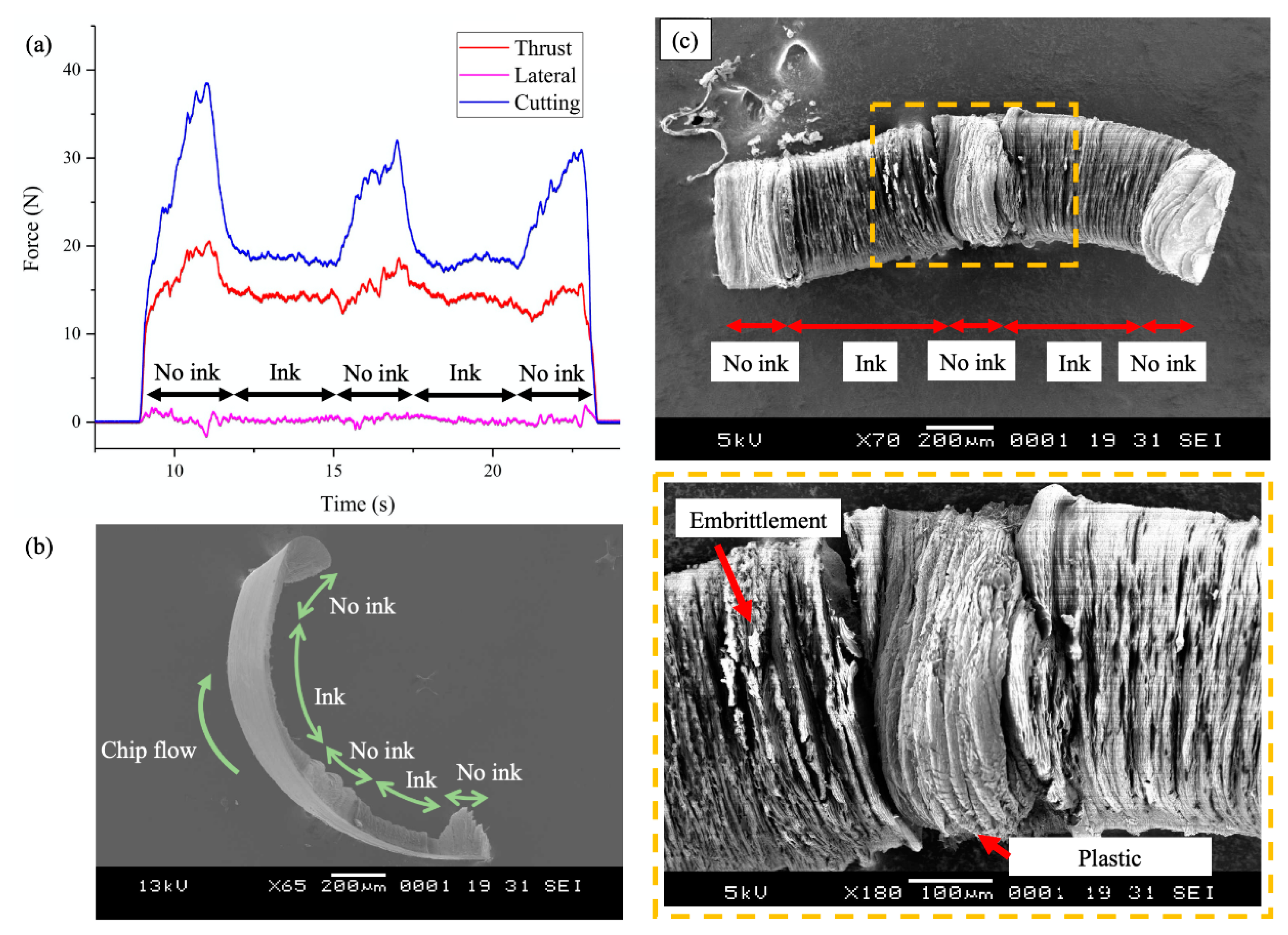
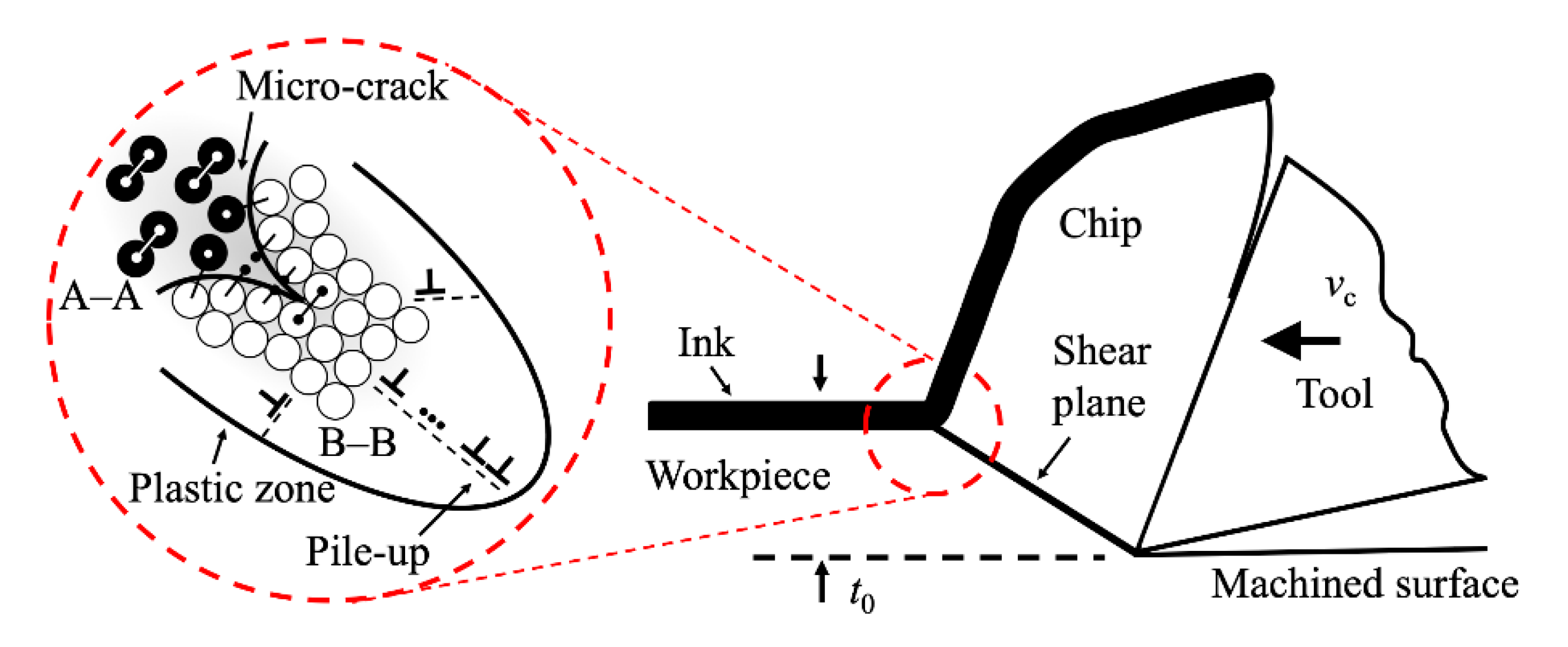
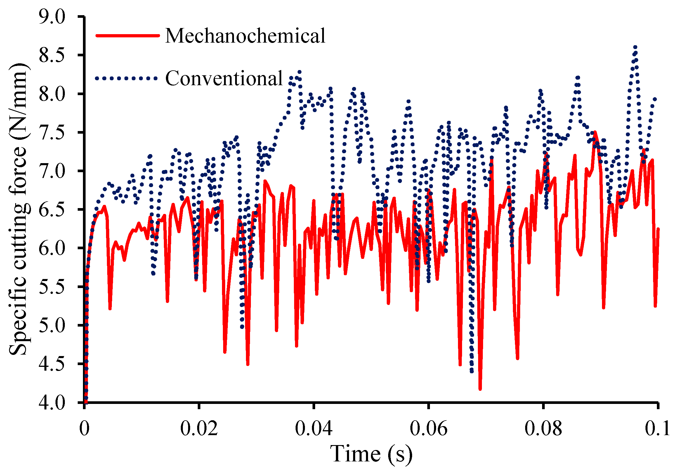
  • The phenomenon is validated on iron by a 30% reduction in cutting forces and the production of thinner chips with embrittlement characteristics during orthogonal microcutting with a cubic boron nitride (CBN) cutting tool;
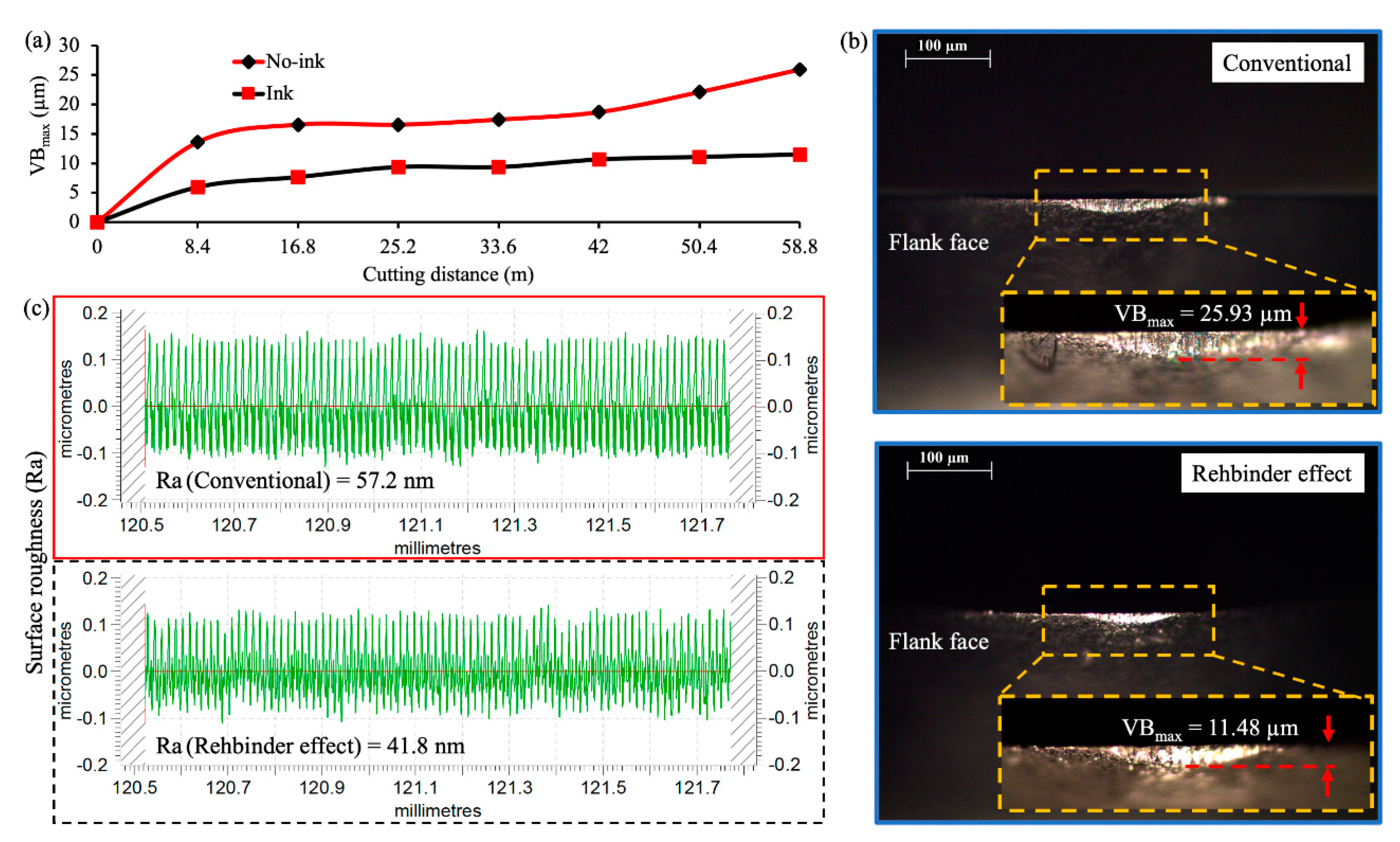
  • Diamond turning with polycrsyalline diamond (PCD) on a chemisorbed workpiece can reduce flank wear by up to 56% and improve the surface roughness by 27% over a machining distance of 58.8 m;
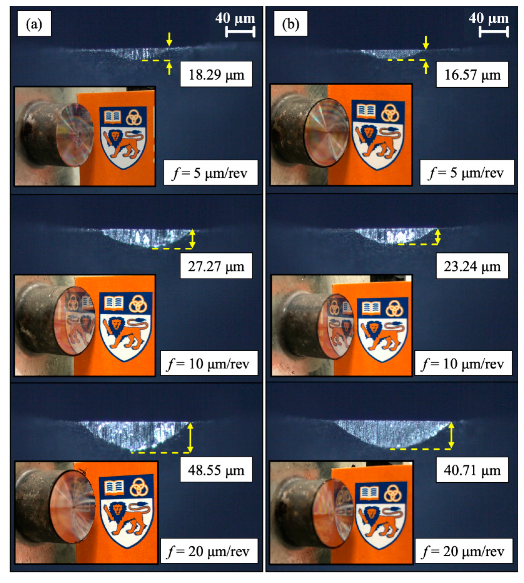
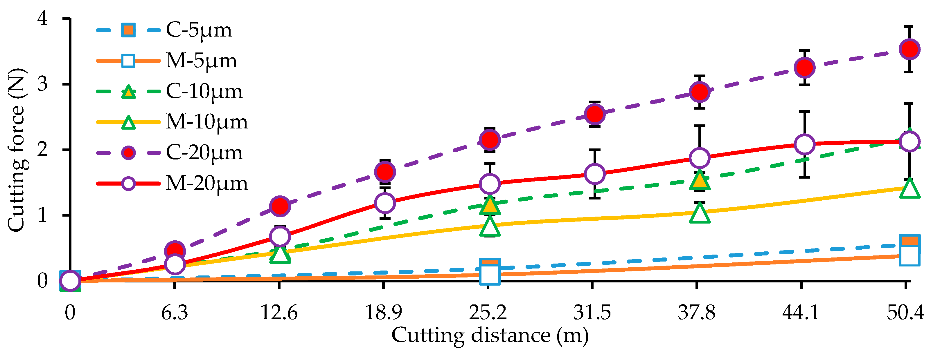
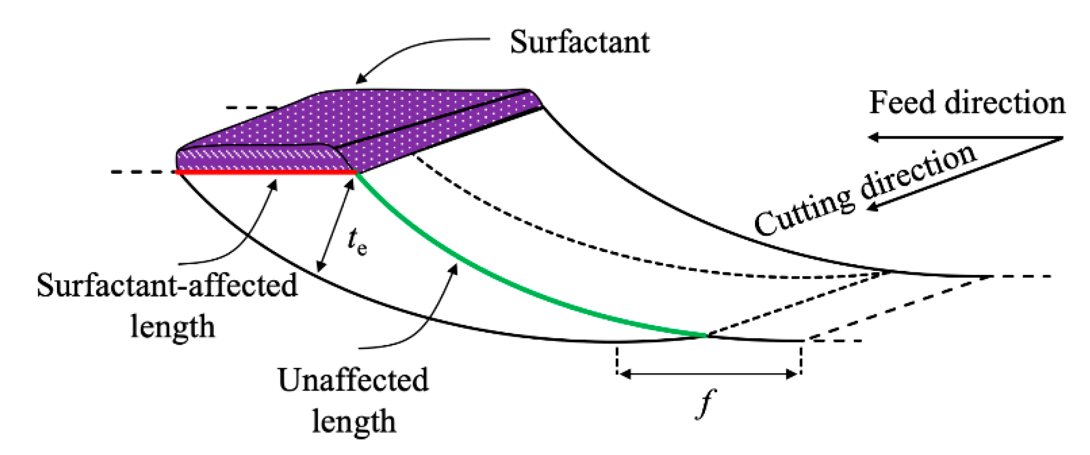
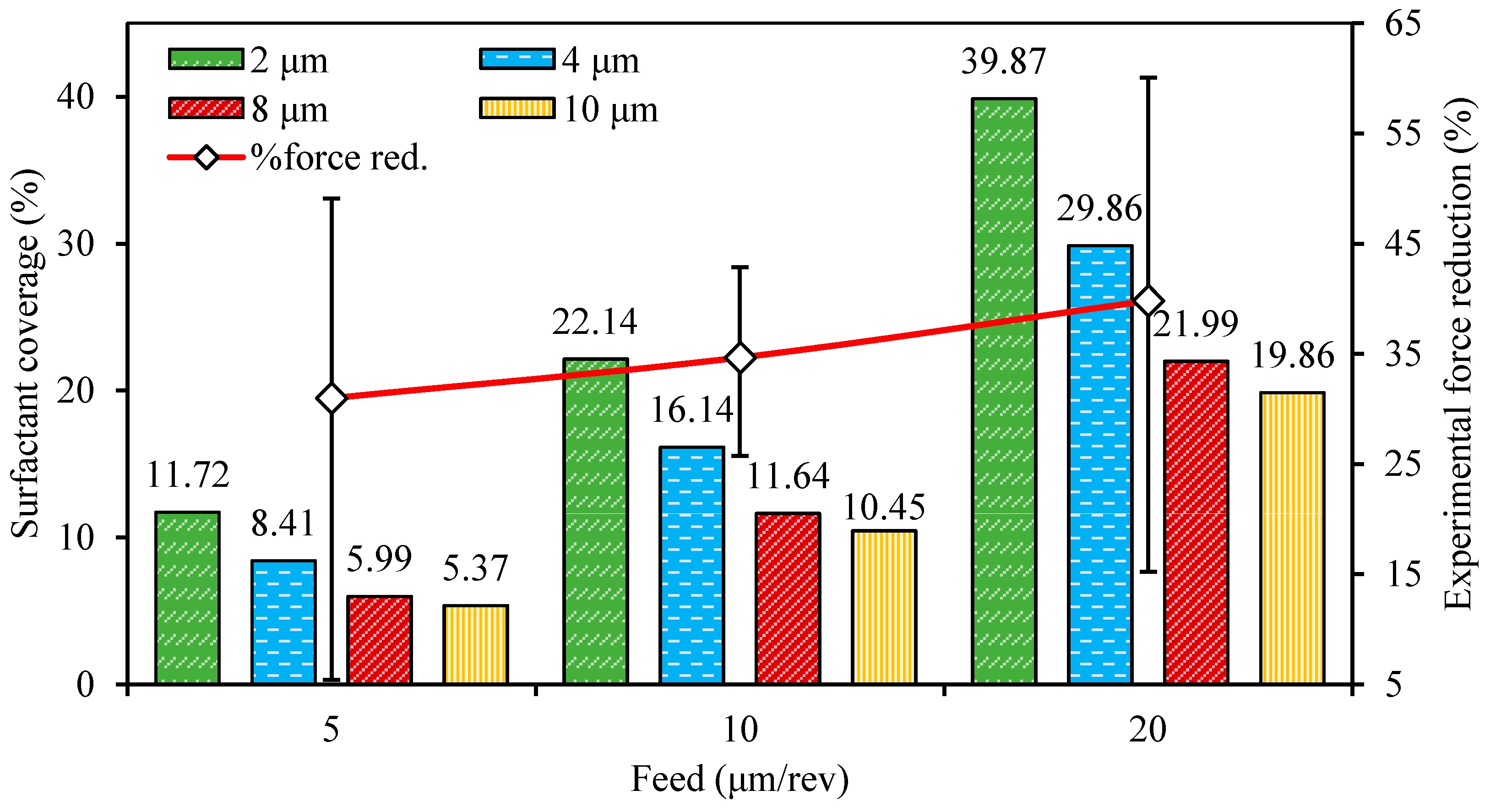
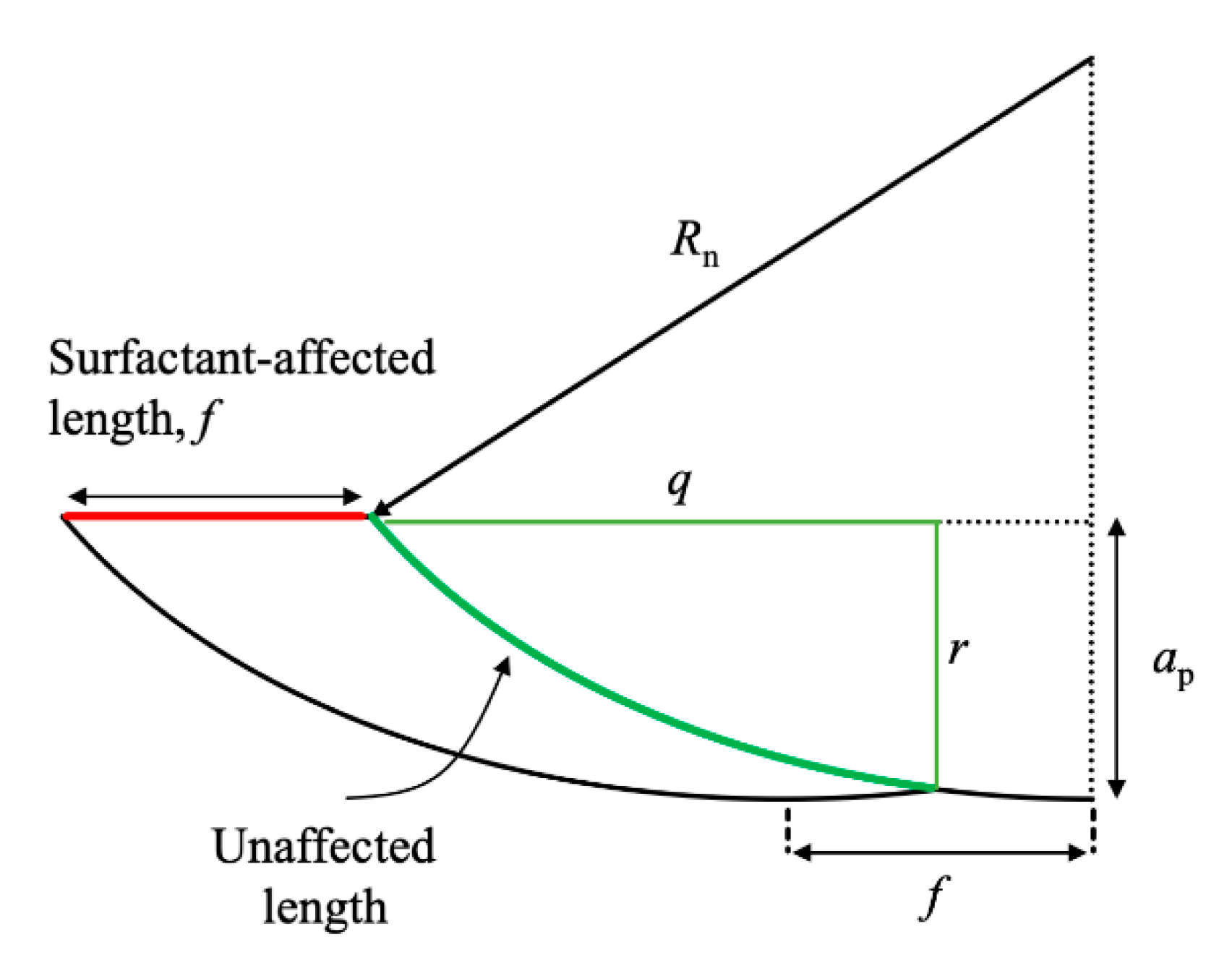
  • The percentage reduction in cutting forces and tool wear during diamond turning with the mechanochemical effect increases with feed due to the enlargement of effective uncut chip thickness and surfactant-affected material;
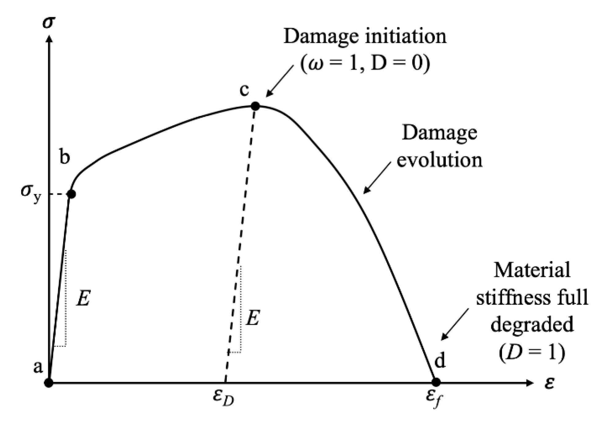
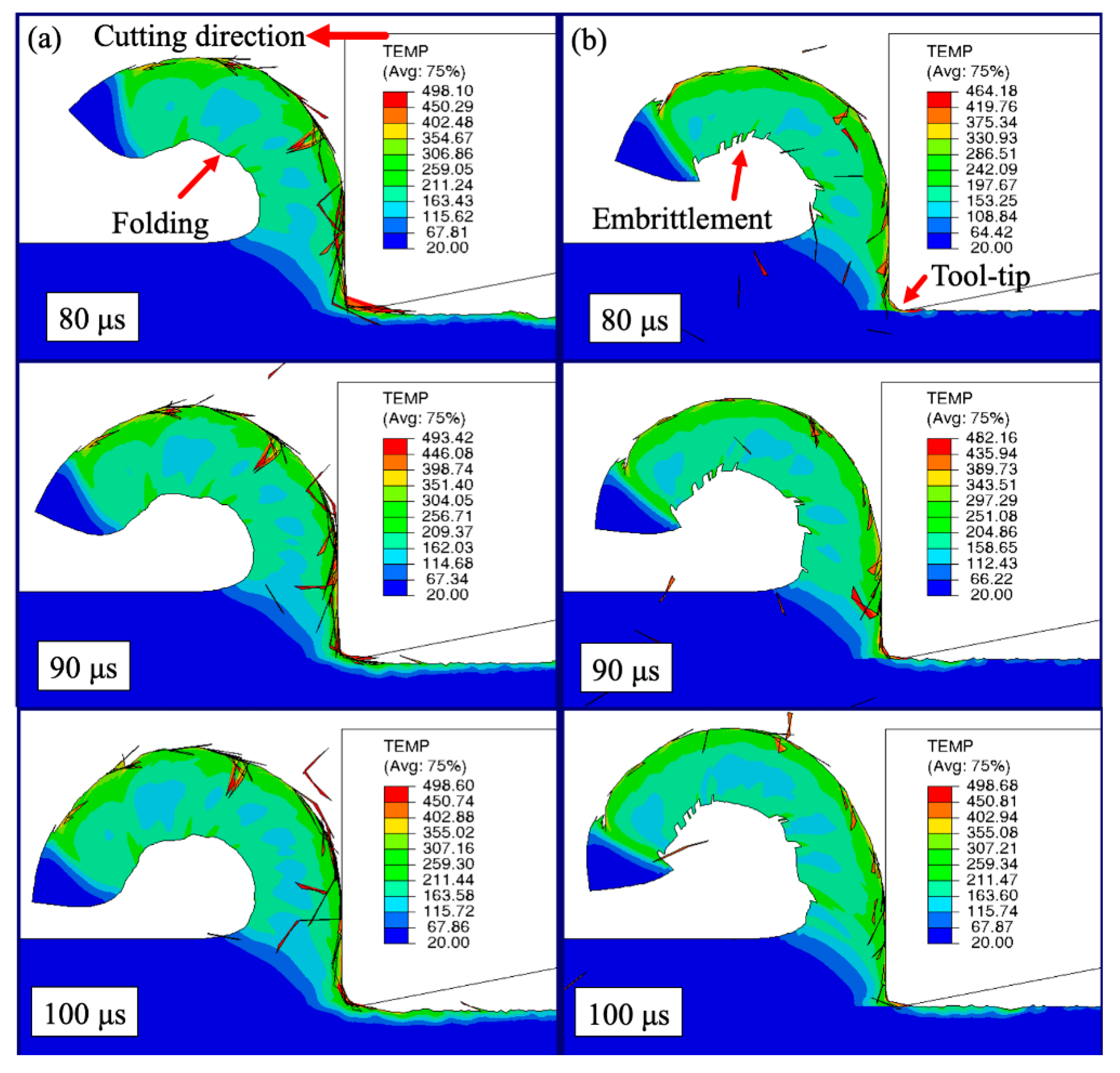
  • A finite element model utilizes the fracture energy parameter to simulate the chemisorption effect and demonstrate the reduction in chip thickness, shorter tool–chip contact, chip embrittlement, and the reduction in heat generation on the machined surface; and
  • It is proposed that although heat generation can be reduced to mitigate diamond tool wear due to lower cutting energies under the mechanochemical effect, the heat generated during strain localization also contributes to the overall cutting temperature, to the extent that the reduction in tool wear does not coincide with the reduction in cutting forces or surfactant coverage.

Author Contributions

Conceptualization, Y.J.L. and H.W.; methodology, Y.J.L. and H.W.; validation, Y.J.L.; formal analysis, Y.J.L. and Y.-K.S.; investigation, Y.J.L.; resources, H.W.; writing—original draft preparation, Y.J.L. and Y.-K.S.; writing—review and editing, H.W.; visualization, Y.-K.S.; supervision, H.W.; funding acquisition, H.W. All authors have read and agreed to the published version of the manuscript.

Funding

This research was funded by the Singapore Ministry of Education Academic Research Fund (Grant Nos.: R-265-000-686-114 and MOE2018-T2-1-140).

Acknowledgments

The authors would like to thank Yeo Eng Huat, Nelson (AML, NUS) and Jiahao Zhang for their assistance in the experimental work.

Conflicts of Interest

The authors declare no conflict of interest.

Appendix A

This section will detail the equations to determine the unaffected material length to be used during diamond turning with a surfactant. Figure A1 illustrates the front view of the diamond turning process. The unaffected material length takes an elliptical form with radii q and r, which may be determined by geometry in Equations (A1) and (A2), where Rn and ap are the nose radius and nominal depth of cut, respectively. The perimeter of the quarter-ellipse p can then be calculated in Equations (A3) and (A4):
q = ( R n 2 ( R n a p ) 2 ) 1 2 0.5 f
r = a p R n + ( R n 2 ( 0.5 f ) 2 ) 1 2
p = 0.25 π ( q + r ) ( 1 + 3 h 10 + 4 3 h )
where
h = ( q r q + r ) 2
Figure A1. Front view illustration of the diamond turning process for the calculation of the unaffected material length.
Jmmp 04 00081 g0a1

References

  1. Chen, Y.; Zhang, L. Understanding the material removal mechanisms. In Polishing of Diamond Materials: Mechanisms, Modeling and Implementation; Springer: London, UK, 2013; pp. 11–23. ISBN 1849964084. [Google Scholar]
  2. Zhang, X.Q.; Woon, K.S.; Rahman, M. Diamond turning. In Comprehensive Materials Processing; Elsevier: Amsterdam, The Netherlands, 2014; Volume 11, pp. 201–220. ISBN 9780080965338. [Google Scholar]
  3. Riemer, O. Advances in Ultra Precision Manufacturing. In Proceedings of the Japan Society for Precision Engineering, Kanazawa, Japan, 20–22 September 2011. [Google Scholar]
  4. Brinksmeier, E.; Preuss, W. Micro-Machining. Philos. Trans. R. Soc. A 2012, 370, 3973–3992. [Google Scholar] [CrossRef] [PubMed]
  5. Wilks, J. Performance of diamonds as cutting tools for precision machining. Precis. Eng. 1980, 2, 57–72. [Google Scholar] [CrossRef]
  6. Cheng, K.; Huo, D. Micro-Cutting: Fundamentals and Applications; Cheng, K., Huo, D., Eds.; John Wiley & Sons, Ltd.: West Sussex, UK, 2013; ISBN 9780470972878. [Google Scholar]
  7. Dewidar, M.M.; Khalil, K.A.; Lim, J.K. Processing and mechanical properties of porous 316L stainless steel for biomedical applications. Trans. Nonferr. Met. Soc. China 2007, 17, 468–473. [Google Scholar] [CrossRef]
  8. Niinomi, M. Recent metallic materials for biomedical applications. Metall. Mater. Trans. A 2002, 33, 477–486. [Google Scholar] [CrossRef]
  9. Li, Z.J.; Fang, F.Z.; Gong, H.; Zhang, X.D. Review of diamond-cutting ferrous metals. Int. J. Adv. Manuf. Technol. 2013, 68, 1717–1731. [Google Scholar] [CrossRef]
  10. Paul, E.; Evans, C.J.; Mangamelli, A.; Mcglauflin, M.L.; Polvanit, R.S. Chemical aspects of tool wear in single point diamond turning. Precis. Eng. 1996, 18, 4–19. [Google Scholar] [CrossRef]
  11. Casstevens, J.M. Diamond turning of steel in carbon-saturated atmospheres. Precis. Eng. 1983, 5, 9–15. [Google Scholar] [CrossRef]
  12. Evans, C.; Bryan, J.B. Cryogenic diamond turning of stainless steel. CIRP Ann. Manuf. Technol. 1991, 40, 571–575. [Google Scholar] [CrossRef]
  13. Brinksmeier, E.; Gläbe, R. Advances in precision machining of steel. CIRP Ann. 2001, 50, 385–388. [Google Scholar] [CrossRef]
  14. Brinksmeier, E.; Gläbe, R. Precision Machining of Steel with Ultrasonically Driven Chilled Diamond Tools. In Proceedings of the American Society for Precision Engineering, St. Louis, MO, USA, 20–25 October 2002. [Google Scholar]
  15. Shamoto, E.; Moriwaki, T. Ultaprecision diamond cutting of hardened steel by applying elliptical vibration cutting. Ann. CIRP 1999, 48, 441–444. [Google Scholar] [CrossRef]
  16. Wang, Y.; Suzuki, N.; Shamoto, E.; Zhao, Q. Investigation of tool wear suppression in ultraprecision diamond machining of die steel. Precis. Eng. 2011, 35, 677–685. [Google Scholar] [CrossRef]
  17. Hartley, N.E.W. Mechanical property improvements on ion implanted diamond. Metastab. Mater. Form. Ion Implant. 1982, 7, 295–301. [Google Scholar] [CrossRef]
  18. Lee, Y.J.; Hao, L.; Lüder, J.; Chaudhari, A.; Wang, S.; Manzhos, S.; Wang, H. Micromachining of ferrous metal with an ion implanted diamond cutting tool. Carbon N. Y. 2019, 152, 598–608. [Google Scholar] [CrossRef]
  19. Zhang, X.; Liu, K.; Kumar, A.S.; Rahman, M. A study of the diamond tool wear suppression mechanism in vibration-assisted machining of steel. J. Mater. Process. Technol. 2014, 214, 496–506. [Google Scholar] [CrossRef]
  20. Zhang, X.; Deng, H.; Liu, K. Oxygen-Shielded ultrasonic vibration cutting to suppress the chemical wear of diamond tools. CIRP Ann. 2019, 68, 69–72. [Google Scholar] [CrossRef]
  21. Grosskreutz, J.C. The effect of oxide films on dislocation-surface interactions in aluminium. Surf. Sci. 1967, 8, 173–190. [Google Scholar] [CrossRef]
  22. Shimada, S.; Tanaka, H.; Higuchi, M.; Yamaguchi, T.; Honda, S.; Obata, K. Thermo-Chemical wear mechanism of diamond tool in machining of ferrous metals. CIRP Ann. Manuf. Technol. 2004, 53, 57–60. [Google Scholar] [CrossRef]
  23. Lee, Y.J.; Wang, H. Current understanding of surface effects in microcutting. Mater. Des. 2020, 192, 108688. [Google Scholar] [CrossRef]
  24. Malkin, A.I. Regularities and mechanisms of the Rehbinder’s effect. Colloid J. 2012, 74, 223–238. [Google Scholar] [CrossRef]
  25. Rehbinder, P.A. On the effect of changes in the surface energy upon cleavage, hardness, and other crystal properties. In Proceedings of the VI-th Congress of Russian Physicists, Moscow, Russia, 5–16 August 1928; p. 29. [Google Scholar]
  26. Chaudhari, A.; Soh, Z.Y.; Wang, H.; Kumar, A.S. Rehbinder effect in ultraprecision machining of ductile materials. Int. J. Mach. Tools Manuf. 2018, 133, 47–60. [Google Scholar] [CrossRef]
  27. Udupa, A.; Viswanathan, K.; Saei, M.; Mann, J.B.; Chandrasekar, S. Material-Independent mechanochemical effect in the deformation of highly-strain-hardening metals. Phys. Rev. Appl. 2018, 10, 1. [Google Scholar] [CrossRef] [Green Version]
  28. Yeung, H.; Viswanathan, K.; Compton, W.D.; Chandrasekar, S. Sinuous flow in metals. Proc. Natl. Acad. Sci. USA 2015, 112, 9828–9832. [Google Scholar] [CrossRef] [PubMed] [Green Version]
  29. Chaudhari, A.; Wang, H. Effect of surface-active media on chip formation in micromachining. J. Mater. Process. Technol. 2019, 271, 325–335. [Google Scholar] [CrossRef]
  30. Atkins, A.G. Modelling metal cutting using modern ductile fracture mechanics: Quantitative explanations for some longstanding problems. Int. J. Mech. Sci. 2003, 45, 373–396. [Google Scholar] [CrossRef]
  31. Atkins, A.G.; Liu, J.H. Toughness and the transition between cutting and rubbing in abrasive contacts. Wear 2007, 262, 146–159. [Google Scholar] [CrossRef]
  32. Chan, C.Y.; Lee, W.B.; Wang, H. Enhancement of surface finish using water-miscible nano-cutting fluid in ultra-precision turning. Int. J. Mach. Tools Manuf. 2013, 73, 62–70. [Google Scholar] [CrossRef]
  33. Shchukin, E.D. The influence of surface-active media on the mechanical properties of materials. Adv. Colloid Interface Sci. 2006, 123, 33–47. [Google Scholar] [CrossRef]
  34. Simoneau, A.; Ng, E.; Elbestawi, M.A. Surface defects during microcutting. Int. J. Mach. Tools Manuf. 2006, 46, 1378–1387. [Google Scholar] [CrossRef]
  35. Simoneau, A.; Ng, E.; Elbestawi, M.A. Chip formation during microscale cutting of a medium carbon steel. Int. J. Mach. Tools Manuf. 2006, 46, 467–481. [Google Scholar] [CrossRef]
  36. Simoneau, A.; Ng, E.; Elbestawi, M.A. Grain size and orientation effects when microcutting AISI 1045 steel. CIRP Ann. 2007, 56, 57–60. [Google Scholar] [CrossRef]
  37. Lee, Y.J.; Chong, J.Y.; Chaudhari, A.; Wang, H. Enhancing ductile-mode cutting of calcium fluoride single crystals with solidified coating. Int. J. Precis. Eng. Manuf. Technol. 2019, 1–11. [Google Scholar] [CrossRef]
  38. Wang, H.; To, S.; Chan, C.Y. Investigation on the influence of tool-tip vibration on surface roughness and its representative measurement in ultra-precision diamond turning. Int. J. Mach. Tools Manuf. 2013, 69, 20–29. [Google Scholar] [CrossRef]
  39. Rahman, M.A.; Amrun, M.R.; Rahman, M.; Kumar, A.S. Variation of surface generation mechanisms in ultra-precision machining due to relative tool sharpness (RTS) and material properties. Int. J. Mach. Tools Manuf. 2017, 115, 15–28. [Google Scholar] [CrossRef]
  40. Zhao, T.; Zhou, J.M.; Bushlya, V.; Ståhl, J.E. Effect of cutting edge radius on surface roughness and tool wear in hard turning of AISI 52100 steel. Int. J. Adv. Manuf. Technol. 2017, 91, 3611–3618. [Google Scholar] [CrossRef] [Green Version]
  41. Gavriljuk, V.G.; Shanina, B.D.; Shyvanyuk, V.N.; Teus, S.M. Electronic effect on hydrogen brittleness of austenitic steels. J. Appl. Phys. 2010, 108, 83723. [Google Scholar] [CrossRef]
  42. Teus, S.M.; Shanina, B.D.; Konchits, A.A.; Mogilny, G.S.; Gavriljuk, V.G. Mechanism of embrittlement of metals by surface-active elements. Metallofiz. Noveishie Tekhnologii 2018, 40, 201–218. [Google Scholar] [CrossRef]
  43. Wang, H.; To, S.; Chan, C.Y.; Cheung, C.F.; Lee, W.B. Elastic strain induced shear bands in the microcutting process. Int. J. Mach. Tools Manuf. 2010, 50, 9–18. [Google Scholar] [CrossRef]
  44. Abukhshim, N.A.; Mativenga, P.T.; Sheikh, M.A. Heat generation and temperature prediction in metal cutting: A review and implications for high speed machining. Int. J. Mach. Tools Manuf. 2006, 46, 782–800. [Google Scholar] [CrossRef]
  45. Toropov, A.; Ko, S.-L. Prediction of tool-chip contact length using a new slip-line solution for orthogonal cutting. Int. J. Mach. Tools Manuf. 2003, 43, 1209–1215. [Google Scholar] [CrossRef]
  46. Komanduri, R.; Hou, Z.B. Thermal modeling of the metal cutting process—Part II: Temperature rise distribution due to frictional heat source at the tool-chip interface. Int. J. Mech. Sci. 2001, 43, 57–88. [Google Scholar] [CrossRef]
  47. Narulkar, R.; Bukkapatnam, S.; Raff, L.M.; Komanduri, R. Graphitization as a precursor to wear of diamond in machining pure iron: A molecular dynamics investigation. Comput. Mater. Sci. 2009, 45, 358–366. [Google Scholar] [CrossRef]
  48. Johnson, R.G.; Cook, W. A constitutive model and data for metals subjected to large strains, high strain rates and high temperatures. In Proceedings of the Seventh International Symposium on Ballistics, The Hague, The Netherlands, 18–21 April 1983. [Google Scholar]
  49. Elango, P.; Marimuthu, K.P. Numerical validation of drilling of Al6061-T6 with experimental data. Mech. Mech. Eng. 2019, 23, 287–290. [Google Scholar] [CrossRef] [Green Version]
  50. Akram, S.; Jaffery, S.H.I.; Khan, M.; Fahad, M.; Mubashar, A.; Ali, L. Numerical and experimental investigation of Johnson-Cook material models for aluminum (Al 6061-T6) alloy using orthogonal machining approach. Adv. Mech. Eng. 2018, 10. [Google Scholar] [CrossRef] [Green Version]
  51. Hillerborg, A.; Modéer, M.; Petersson, P.-E. Analysis of crack formation and crack growth in concrete by means of fracture mechanics and finite elements. Cem. Concr. Res. 1976, 6, 773–781. [Google Scholar] [CrossRef]
  52. Atlati, S.; Haddag, B.; Nouari, M.; Zenasni, M. Analysis of a new Segmentation Intensity Ratio “SIR” to characterize the chip segmentation process in machining ductile metals. Int. J. Mach. Tools Manuf. 2011, 51, 687–700. [Google Scholar] [CrossRef]
  53. Zhang, Y.C.; Mabrouki, T.; Nelias, D.; Gong, Y.D. Chip formation in orthogonal cutting considering interface limiting shear stress and damage evolution based on fracture energy approach. Finite Elem. Anal. Des. 2011, 47, 850–863. [Google Scholar] [CrossRef]
  54. Mabrouki, T.; Girardin, F.; Asad, M.; Rigal, J.-F. Numerical and experimental study of dry cutting for an aeronautic aluminium alloy (A2024-T351). Int. J. Mach. Tools Manuf. 2008, 48, 1187–1197. [Google Scholar] [CrossRef]
Figure 1. Experimental setup and the schematic for microcutting experiments.
Jmmp 04 00081 g001
Figure 2. (a) Scanning electron microscopic (SEM) image of the as received cutting tool edge; and (b) the tool edge radius measurement using a MikroCAD 3D optical imaging system.
Jmmp 04 00081 g002
Figure 3. Microgroove chip formation of iron with a cubic boron nitride (CBN) tool at t0 = 12 µm and vc = 50 mm/min: (a) the measured machining forces; (b) the SEM image of chip formation; and (c) SEM top view of the chip.
Jmmp 04 00081 g003
Figure 4. Optical imaging of the machined surfaces.
Jmmp 04 00081 g004
Figure 5. (a) Wear land (VBmax) progression of the polycrystalline diamond (PCD) turning of iron; (b) the arithmetic mean height (Ra) of after cutting a distance of 58.8 m with and without ink; and (c) optical the imaging of the corresponding tool wear land.
Jmmp 04 00081 g005
Figure 6. Diamond cutting tool flank wear and the corresponding machined surface quality of iron after cutting a total distance of 50.66 m under different feeds: (a) conventional; and (b) with the mechanochemical effect.
Jmmp 04 00081 g006
Figure 7. Machining force progression in diamond tool wear tests under conventional cutting conditions (C) and the mechanochemical effect (M) with feeds of 5, 10 and 20 μm/rev.
Jmmp 04 00081 g007
Figure 8. Geometrical relationship between the feed and the mechanochemical effect.
Jmmp 04 00081 g008
Figure 9. Proportion of the surfactant-affected material in relation to the nominal cutting depths (ap = 2, 4, 8, 10 μm) and feed (f = 5, 10, 20 μm/rev) and the percentage reduction in cutting force from the experimental results.
Jmmp 04 00081 g009
Figure 10. Schematic of the microcrack propagation from the free surface of the adsorbed chip [23].
Jmmp 04 00081 g010
Figure 11. Schematic of the primary deformation zone (PDZ), the secondary deformation zone (SDZ) and the tertiary deformation zone (TDZ).
Jmmp 04 00081 g011
Figure 12. Johnson–Cook stress–strain relationship.
Jmmp 04 00081 g012
Figure 13. Simulated chip morphology and temperature profile under (a) conventional cutting conditions and (b) the mechanochemical effect.
Jmmp 04 00081 g013
Figure 14. Plot of the theoretical specific cutting forces under conventional cutting conditions and with the mechanochemical effect.
Jmmp 04 00081 g014
Table 1. Diamond tool wear mitigation techniques to machine ferrous metals.
ModificationTheoretical ApproachApplication
Process Reducing temperaturesCryogenic turning [12,13,14]
Prohibition of chemical reactionsMachining in inert environments [10,11]
Reducing tool–workpiece contact timeUltrasonic vibration assisted machining [15,16]
Tool Prohibition of chemical reactionsProtective coatings [13]
Inhibiting reaction ratesIon implantation [17,18]
Workpiece Prohibition of chemical reactionsSurface compound layer formation [13]
Table 2. Diamond tool wear mitigation techniques to machine ferrous metals.
CMnSiPSCrNiVTiAlFe
0.020.350.150.030.0250.20.150.10.10.1Bal.
Table 3. AA6061-T6 Johnson–Cook material parameters [49].
E (GPa)vρ (g/cm3)A (MPa)B (MPa)nCmcp (J/g°C)Tm (°C)k (W/m°C)
700.332.7324.1113.80.0020.0111.34896583167
Table 4. AA6061-T6 Johnson–Cook failure parameters [50].
D1D2D3D4D5
−0.771.45−0.4701.6

