Article

Partition of Primary Shear Plane Heat in Orthogonal Metal Cutting

1
MAPEX Center for Materials and Processes, Faculty of Production Engineering, University of Bremen, Badgasteiner Straße 1, 28359 Bremen, Germany
2
Leibniz Institute for Materials Engineering IWT, Badgasteiner Straße 3, 28359 Bremen, Germany
*
Author to whom correspondence should be addressed.
J. Manuf. Mater. Process. 2020, 4(3), 82; https://doi.org/10.3390/jmmp4030082
Submission received: 6 July 2020 / Revised: 8 August 2020 / Accepted: 12 August 2020 / Published: 13 August 2020
(This article belongs to the Special Issue Advances in Modelling of Machining Operations)

Abstract

:
When assessing the effect of metal cutting processes on the resulting surface layer, the heat generated in the chip formation zone that is transferred into the workpiece is of major concern. Models have been developed to estimate temperature distributions in machining processes. However, most of them need information on the heat partition as input for the calculations. Based on analytical and numerical models, it is possible to determine the fraction of shear plane heat transferred into the workpiece for orthogonal cutting conditions. In the present work, these models were utilized to gain information on the significant influencing factors on heat partition, based on orthogonal cutting experiments, experimental results from the literature, and a purely model-based approach. It could be shown that the heat partition does not solely depend on the cutting velocity, the uncut chip thickness, and the thermal diffusivity—combined in the dimensionless thermal number—but the shear angle also has to be taken into account, as already proposed by some researchers. Furthermore, developed numerical models show that a more realistic representation of the process kinematics, e.g., regarding chip flow and temperature-dependent material properties, do not have a relevant impact on the heat partition. Nevertheless, the models still assume an idealized orthogonal cutting process and comparison to experimental-based findings on heat partition indicates a significant influence of the cutting edge radius and the friction on the flank face of the tool.

1. Introduction

In machining, the predominant part of the cutting energy caused by the occurring loads is liberated as thermal energy in the primary shear zone, due to plastic deformation. The amount of generated heat strongly depends on the process forces and, thus, on the shear flow stress, which, inter alia, is temperature-dependent and therefore results in thermal softening for increasing temperatures. In addition to the amount of generated heat, the temperature during machining and its distribution are also defined by heat transfer mechanisms. The fraction of heat transferred into the workpiece, chip, tool, and metal working fluid depends on the thermal material properties and the machining parameters as well as on the fluid supply conditions, e.g., nozzle type and flow rate. Surface and subsurface properties of the workpiece, such as the residual stress state, are highly affected through the occurring thermal load during machining, i.e., the temperature distribution and the involved temperature gradients [1]. Thermally activated material modifications, in the worst-case thermal damage, might impair the functional performance of the part [2]. Therefore, understanding and predicting the fraction of heat transferred into the workpiece is of major concern. According to Shaw, 90% of the induced heat in metal cutting dissipates into the chip [3]. Segurajauregui and Arrazola show that the heat partition in drilling depends on machining parameters, i.e., increasing the cutting velocity or the feed rate results in a decreased fraction of the heat transferred into the workpiece [4]. Fleischer et al. give an overview of the range of heat partition between tool, chip, and workpiece for different manufacturing processes, showing significant differences [5]. The same conclusion can be drawn from investigations by Sölter et al., in which heat partitions for turning, milling, and drilling processes under dry conditions, and for different types of steel and aluminum, have been determined based on temperature measurements [6]. In order to understand and quantitatively predict these differences, a thermal analysis taking into account both the heat partition at the chip formation zone and the removal of preheated workpiece material regions by subsequent cutting-edge engagements is necessary. While the latter depends on the type of machining process, e.g., conceptually shown for face milling by Langenhorst et al. [7], the first has been addressed by many researchers using orthogonal cutting kinematics and Merchant’s two dimensional, plain strain shear plane model [8] for a theoretical determination of temperature fields. However, these approaches are based on different modeling assumptions and, thus, neglect and postulate different influencing factors on the heat partition. A comparison between the models’ results using the latest computational power and additionally with recently published experimental data on heat partition with the aim of determining the relevant influencing factors has not yet been carried out. To fill this research gap, the objective of the present work is the investigation of influencing factors on the fraction of shear plane heat transferred into the workpiece, calculated by means of the most promising of these modeling approaches. An evaluation of the prediction accuracy has been conducted by a comparison with measured results on heat partition in orthogonal metal cutting.

2. State of the Art on Heat Partition in Orthogonal Metal Cutting

2.1. Analytical Modeling Approaches

In most of the early metal cutting analyses, the moving heat source theory based on Jaeger [9] is commonly applied to analytically calculate temperatures. Jaeger’s approach provides a heat source moving along the surface of a semi-infinite solid with an adiabatic boundary. Loewen and Shaw, for example, proposed that the primary shear zone in orthogonal cutting can be assumed as a heat source moving over the workpiece surface with the shearing velocity [10]. In this case, the heat source separates two bodies in sliding contact, namely the workpiece and the chip. In two-body approaches, information about the heat partition is needed as an input parameter to match temperatures occurring at the contact of both bodies. The heat partition can either be measured by extensive and highly challenging calorimetric experiments or determined by iteratively matching calculated with measured temperatures. The latter is often applied to generate empirical models for the heat partition in industrially relevant processes, e.g., by Grzesik and Nieslony, for dry turning with multi-layer coated tools [11], by Sölter and Gulpak for dry milling of normalized AISI 4140 steel [12], and for grinding by Malkin and Guo [13]. Apart from these comparatively time-consuming methods, already in 1951, Hahn proposed a one-body approach to analytically calculate temperature fields in an infinite medium, without the need of a priori knowledge of heat partition [14]. In his study, he developed a general solution of the 2D heat conduction equation for a moving band heat source moving obliquely in an infinite medium, in which both the conductive heat transport and the convective heat transport due to mass flow are considered. In fact, the previously mentioned Jaeger solution is a special case also represented in Hahn’s approach. Fifty years later, Komanduri and Hou discussed analytical one-body and two-body approaches in detail, and utilized Hahn’s approach to calculate temperature fields and heat partition in orthogonal cutting [15]. Based on Chao and Trigger’s idea [16] to adjust Hahn’s model to orthogonal cutting conditions by mathematically implementing adiabatic boundaries, they add a mirrored, so-called imaginary heat source (Figure 1). Temperature fields due to heat input at the primary shear plane were calculated in two separate subsystems for the chip and the workpiece side. Their model provides the heat partition between chip and workpiece by calculating a stationary temperature distribution between both bodies. However, only the one adiabatic boundary along the direction of motion has been considered for mathematically reasons. Due to the change in motion at the primary shear plane in both subsystems, temperatures will be calculated in imaginary parts not representing the actual material in orthogonal cutting. By combining both subsystems and additionally neglecting the imaginary parts, according to Komanduri and Hou, temperature fields with good agreement to reality can be obtained.
Based on their model, Komanduri and Hou provide an assumed functional relation for the heat partition in orthogonal cutting. They support Chao and Trigger’s assumption that the heat partition at the primary shear plane solely depends on the thermal number Nth = h · vc · a−1, where h denotes the uncut chip thickness, vc the cutting velocity and a the thermal diffusivity of the workpiece material [16]. In general, the literature on heat transfer referred to as Peclet-number, the thermal number describes the relation of convective heat transport by mass flow (h · vc) and diffusive heat transport (a−1). In their investigations, Chao and Trigger varied the thermal number solely through the cutting velocity and the depth of cut, as they investigated only one material. Therefore, their proposed dependency of the heat partition on the thermal number was not valid for metal cutting in general. Komanduri and Hou determined the fraction of shear plane heat transferred into the workpiece for different materials and, as a result, variations of the thermal diffusivity. However, their proposed regression function is based on only four calculated values. Moreover, to assure short computation times Komanduri and Hou used a comparatively low amount of grid points to calculate the temperature fields. Further investigations regarding the validity of the proposed model are therefore considered necessary by the authors of this publication.
Komanduri and Hou further developed their approach by investigating the temperature rise distribution due to frictional heat source at the tool-chip interface [17], and due to the combined effects of the shear plane heat source and the tool-chip interface frictional heat source [18]. In these investigations, they concluded that the effect of the tool-chip interface frictional heat source on the temperature rise in the workpiece is insignificant and that the temperature rise in the workpiece is mainly due to the effect of the shear plane heat source. Nevertheless, further works based on Komanduri and Hou’s findings mostly study the heat partition behavior between the tool and the chip to determine the thermal load on the tool. The present work focusses on the fraction of heat transferred into the workpiece, therefore only the partition of the shear plane heat is considered. For heat partition on the tool-chip interface, readers are referred to comprehensive works by Karpat and Özel [19], Grzesik [20] and Akbar et al. [21]. In addition to Komanduri and Hou’s findings on the fraction of shear plane heat, Weiner, shortly after Hahn’s contribution, proposed an analytical solution for the temperature distribution along the shear plane in orthogonal cutting in 1955. In his work, he assumed that the chip velocity is perpendicular to the shear plane and that heat conduction in the direction of motion of the workpiece or chip may be neglected without causing a relevant error on the heat partition. By this, he avoids making the same assumption as in Hahn’s and Komanduri and Hou’s approach, in which the change in motion at the shear plane cannot be considered, and no boundary condition can be defined at the newly generated workpiece surface, but still provides a mathematical simplification to the prevailing differential equation for the steady-state temperature field caused by a moving heat source in a semi-infinite solid, with which an analytical solution can be obtained. Based on the calculated temperatures along the shear plane, Weiner determined the heat flow into the chip and related it to the total shear power to derive the fraction of shear plane heat transferred into the workpiece according to Equation (1). His equation for the fraction depends on the thermal number Nth and the shear angle ϕ according to Equation (2). An increase of this dimensionless number Y L leads to a decrease of the fraction of heat transferred into the workpiece.
R n , Weiner = 1 4   ·   Y L   ·   erf   ( Y L ) + ( 1 + Y L )   ·   erfc   ( Y L )     e   Y L π   ·   ( 1 2   ·   Y L + Y L )
Y L = 0 . 25   ·   Nth   · tan ϕ

2.2. Numerical Modeling Approaches

Besides analytical models, more recently, numerical models have been used by researchers to investigate the fraction of primary shear plane heat transferred into the workpiece. The contributions can be divided into two different approaches. First, the orthogonal cutting process is modeled as a steady-state heat source using a uniformly distributed heat flux density along the shear plane and 2D heat transfer elements that include conduction and convection. Utilizing this approach, Deshpande et al. numerically calculated temperature fields and fractions of shear plane heat for machining AISI 1045 with different uncut chip thicknesses and cutting velocities [22]. The fraction of heat transferred into the workpiece plotted over the thermal number Nth times the tangent of the shear angle ϕ shows good agreement with the results from Weiner’s equation. Whereas, for the comparison with Komanduri and Hou’s regression equation, significant deviations were observed. Xia et al. used a similar modeling approach, additionally implementing the frictional heat source at the tool-chip interface and temperature-dependent thermal material properties [23]. As assumed by almost all works in this field, they confirmed that the convective and radiative surface heat loss is insignificant compared to the heat dissipation by the moving material. In comparison to the regression equation by Boothroyd (reference [24], mentioned in the next paragraph) their model calculated higher fractions of heat into the workpiece for thermal numbers Nth < 5 and lower fractions for Nth > 5. No theoretical comparison of the results with calculations using material properties at room temperature has been conducted, so the influence of the temperature dependency cannot be evaluated.
The second type of numerical approaches promise a very accurate solution by transient thermo-mechanical coupled simulations of the chip formation. The heat generation is thereby related to simultaneously calculated strain rates. Thus, the accuracy of chip formation simulations strongly depends on the highly demanding identification and formulation of material constitutive equations, as well as on sub-models describing the tribological and thermal interactions at the tool-chip contact interface. Besides these challenges, the main drawback of these approaches is the extensive computation time which, until today, limits the application even when using the latest computing power. Many researchers tried to find an acceptable compromise between these contradictory demands and contributed to the knowledge on chip formation [25]. Although temperature fields are always part of the solution, only a few of these works investigated the heat partition. The most comprehensive contribution to this matter has been given by Puls et al. for orthogonal cutting of AISI 1045 [26]. Their chip formation model used the coupled Eulerian Lagrangian method and a velocity dependent friction model to calculate steady-state temperature fields. The results have been evaluated with regard to the heat input into the workpiece which was then related to the cutting power calculated by means of the simulated cutting force Fc times the cutting velocity vc. For such calculated fractions of heat transferred into the workpiece, a decrease with increasing cutting velocity and uncut chip thickness was found in qualitative agreement with the analytical approaches. The validity of the thermal number Nth as a decisive factor for heat partition has not been investigated comprehensively due to the missing variation of the workpiece material. However, effects of the rake angle, the cutting edge radius and tool flank wear on the fraction of heat transferred into the workpiece are provided.

2.3. Experimental Approaches

All above mentioned contributions to the prediction of heat partition utilized modeling approaches and thus need experimental validation by means of measured temperatures. However, determining temperatures or temperature fields in the vicinity of the shear zone during cutting is a demanding task [27]. Early works by Boothroyd utilized infrared photographic techniques to measure temperature fields of tubular workpieces which were end machined on a lathe under orthogonal cutting conditions [28]. For an accurate detection, the specimen needed to be pre-heated to about 600 °C. By evaluating the heat flow through a straight line orthogonal to the newly generated workpiece surface Boothroyd also determined the fraction of primary shear plane heat transferred into the workpiece. He also compared his findings with the analytical approach proposed by Weiner, and data shows that the simulation underestimates the fraction transferred into the workpiece. Later, based on his fractions mainly derived for steels with similar thermal properties, he provided a regression equation [24], which has been extensively used to calculate temperature fields in orthogonal cutting, e.g., in a finite difference model introduced by Lazoglu and Altintas [29], and further developed by Ulutan et al. [30], to predict strain fields and residual stresses and by Lazoglu and Bugdayci [31] for end milling. More recently, Augspurger et al. conducted a comprehensive experimental study on heat partition for orthogonal cutting and peripheral milling [32]. With the latest infrared camera technique, he overcame the restrictions of Boothroyd’s work and measured temperature fields during orthogonal cutting for four metal materials, highly deviating in their thermal properties. The highest workpiece temperatures occurred for Inconel 718 and the lowest temperatures for AlMgSi0.5, which corresponds to the proportion regarding the specific cutting forces and thus the heat generation. For the material Ti6Al4V with comparatively low thermal diffusivity, the temperature rise was mainly concentrated in the vicinity of the cutting zone, whereas for the material AISI 1045 with almost the same heat generation but a higher thermal diffusivity, the temperature rise was more distributed within the workpiece. Based on the mean temperature increase over the measured workpiece surface after the cut Augspurger et al. determined the fraction of total heat transferred into the workpiece. Total heat is, again, as in the numerical simulation-based approach by Puls et al., the cutting energy calculated by means of measured cutting forces. For such determined fractions, a regression equation in dependence of the thermal number is proposed to RAugspurger = 0.4815 · Nth−0.302 and the coefficient of determination is stated to be r2 = 0.8206.

2.4. Conclusions from the State of the Art

The state of the art shows that the functional performance and the surface integrity of a part, among others, depend on the thermal load during machining and, thus, on the fraction of heat transferred into the workpiece. This heat partition is influenced by a factor considering the process dependent cutting edge engagements, and a factor considering the heat partition in the shear zone. For the temperature rise in the workpiece, Komanduri and Hou showed that in orthogonal cutting the partition of the primary shear plane heat is of major concern, and generated heat at the tool-chip interface may be neglected. Two very promising analytical modeling approaches aimed at determining the fraction of shear plane heat transferred into the workpiece have been proposed by Komanduri and Hou and Weiner. In their analyses, no a priori knowledge of the heat partition is required and, due to the analytical nature in comparison to empirical models and numerical chip formation simulations, a universal and fast prediction can be achieved. However, modeling assumptions between these two approaches are different, and the results should be compared to evaluate the deviations. Komanduri and Hou determined the fraction of heat for four different workpiece materials and proposed it to depend on the thermal number Nth, only. Weiner also considers a geometrical factor depending on the shear angle ϕ. In Komanduri and Hou the amount of grid points used to calculate the temperature fields is, compared to the available computational power nowadays, comparatively low, which is assumed to affect the calculation of the heat input into the workpiece. Additionally, more process variations leading to different thermal numbers Nth are needed for more precise predictions and to prove whether the shear angle ϕ has also to be taken into account. Developed numerical heat source models promise to consider more influencing factors on the heat partition, e.g., temperature-dependent material properties, and, thus, should lead to a better approximation of reality. A comparison of these advanced models and the analytical models to recently published data on heat partition based on experiments by Augspurger et al. seems worth investigating, and could lead to an assessment of the accuracy of the applied theoretical methods.

3. Objectives and Procedure

The objective of the present work is the investigation of influencing factors on the fraction of shear plane heat transferred into the workpiece in orthogonal metal cutting. For achieving this objective, four research questions listed in Table 1 are addressed. Analytical temperature simulations are provided in the literature by Komanduri and Hou [15] and by Weiner [33]. In contrast to Weiner’s closed-form equation, the results based on Komanduri and Hou‘s model were derived from temperature calculations, with a comparatively low amount of grid points, and were limited to only four variations in orthogonal cutting data. Consequently, the first research question is whether the fraction of heat transferred into the workpiece changes when improving the calculation of heat input by increasing the amount of grid points. For the answer, the literature values of the four variations already used by Komanduri and Hou were again used to recalculate the fraction of heat transferred into the workpiece. The second research question is whether a prediction of the fraction succeeds by solely considering the thermal number Nth or, as proposed by Weiner, the shear angle ϕ has also to be taken into account. Therefore, the improved Komanduri and Hou model was applied to compute a wider set of thermal numbers, and the results were compared to Weiner’s solution. For the wider set, published orthogonal cutting data in the literature was utilized. Furthermore, especially to have data for small thermal numbers, own orthogonal cutting experiments have been conducted and evaluated. For an even broader range, force and shear angle models were used to calculate data for two materials with highly different thermal properties. In particular, process conditions leading to the same thermal number Nth but different shear angles ϕ have been considered. The third research question addresses the influence of further model adjustments to reality. Especially, the influence of temperature-dependent thermal properties on the fraction of heat transferred into the workpiece was investigated. Furthermore, the influences of an adiabatic boundary at the newly generated workpiece surface as considered by Weiner and of a change in motion at the shear plane, by considering mass flow in the chip in the direction of the chip velocity, were evaluated. A model taking into account these adjustments cannot be solved analytically, so a numerical finite-element heat source model was developed, and adjustments were investigated separately. Finally, by answering the fourth research question the accuracy of the utilized models was evaluated. For this purpose, the recently published regression function on heat partition from Augspurger et al. [32] based on temperature measurements was applied. Deviations from modeling approaches are to be expected due to idealized conditions within the models, e.g., perfectly sharp tool versus cutting edge radius and tool wear. The influence of these factors was also evaluated by means of published results from chip formation simulations by Puls et al. [26].

4. Materials and Methods

4.1. Implementation of the Analytical Model by Komanduri and Hou

Komanduri and Hou’s model [15] is a further development of the model by Hahn [14], in which a moving band heat source moves obliquely in an infinite medium. The calculation of the temperature rise is divided into two subsystems, i.e., the workpiece side and the chip side. Equation (3) provides the solution for the temperature rise in a point M(X,Z), valid for both subsystems. For the workpiece side the auxiliary angle is specified by φ = − (90° − ϕ), and the velocity v corresponds to the cutting velocity vc. The solution is obtained using the modified Bessel function of second kind of zero order K0. In this work, Equation (3) is solved for discrete points by means of the software Matlab and numerical integration. Table 2 shows the required input parameters, which were also utilized to calculate the length of the shear plane L = h/sin(ϕ) and the thermal diffusivity a = λ/(ρ · cp).
Δ T M = q . s 2 π λ l i L e   ( X     l i   ·   sin φ )   ·   v 2 a   ·   U   ·   d l i U = [ K 0 [ v 2 a · ( X     l i · sin φ ) 2 + ( Z     l i · cos φ ) 2 ] + K 0 [ v 2 a · ( X     l i · sin φ ) 2 + ( Z + l i · cos φ ) 2 ] ]

4.2. Development of a Finite-Element Model for Calculating Steady-State Temperature Fields

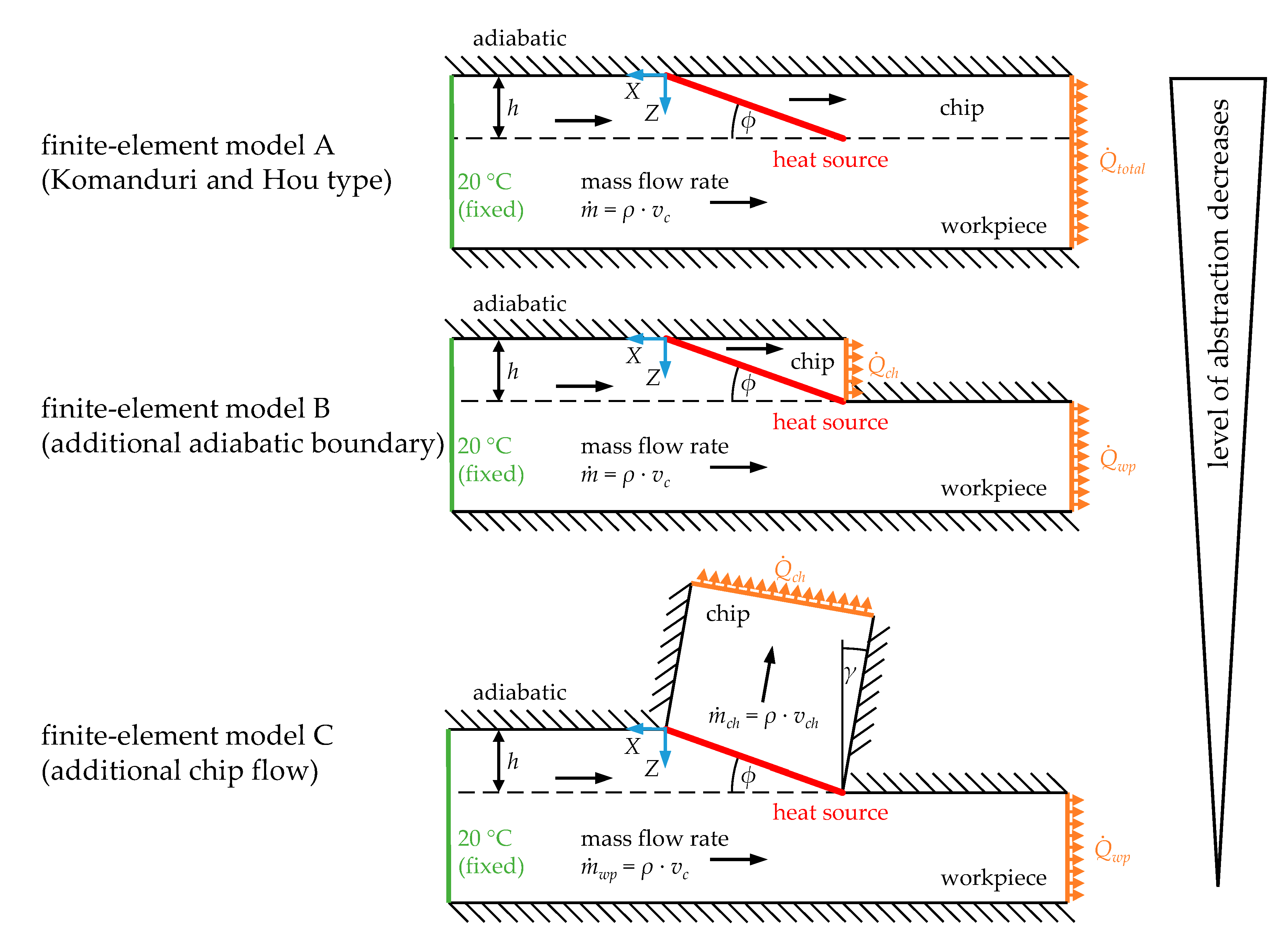
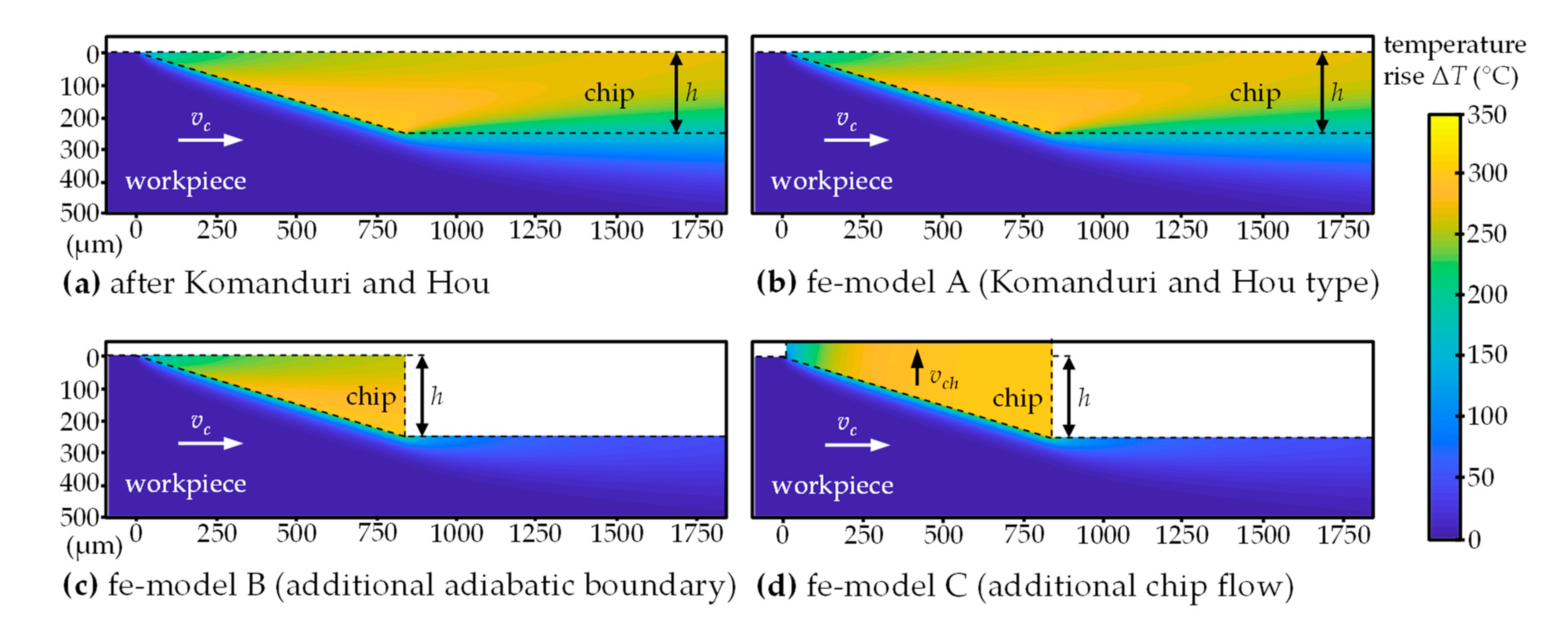
For the purpose of evaluating additional influencing factors on the heat partition, based on the analytical model by Komanduri and Hou, a finite-element model for the calculation of temperature fields is proposed. In Figure 2, the finite-element models A, B, and C considered in this work are presented. In all cases, a steady-state heat transfer problem, discretized by 4-node convection/diffusion finite-elements (type DCC2D4D), was solved by means of the software Abaqus. This type of finite elements enables the implementation of forced convection by defining a mass flow rate. Finite-element model A is a direct representation of the analytical model by Komanduri and Hou. Shear plane heat is liberated at an oblique heat source with a uniform surface heat flux distribution. The mass flow rate is defined in negative X-direction by the multiplication of material density and cutting velocity for all finite-elements. By modeling a boundary condition at the end of the workpiece in positive X-direction, not yet heated material, far away from the heat source, is considered by means of a constant initial temperature of 20 °C. All other boundaries are adiabatic, whereat heat transfer due to convection is permitted at the boundaries perpendicular to the direction of the mass flow rate. Thereby, workpiece dimensions (8 mm ≤ X ≤ 22 mm, 0 mm ≤ Z ≤ 6 mm) are modelled sufficiently large to exclude an influence on the temperature field in the vicinity of the shear plane and to meet the assumption of a semi-infinite body. Due to high temperature gradients, the finite-element length close to the heat source is chosen to be 10 µm and is linearly coarsened to 200 µm at the boundaries. In contrast to finite-element model A, finite-element model B only considers the so-called imaginary part until the end of the shear plane. This leads to an adiabatic boundary at the newly generated workpiece surface, which should be a better approximation of the orthogonal cutting process. The relevance of considering this influencing factor is investigated in this work. A further step to a better approximation of reality is taken in finite-element model C by considering specifics of the chip. Again, all boundaries are adiabatic, except in the direction of the mass flow rate, which now also corresponds to the direction of the chip velocity. For all three models, the fraction of primary shear plane heat transferred into the workpiece was calculated based on simulated temperature fields and by means of the software Matlab. The whole procedure of modeling, calculation, and evaluation is embedded in a fully automatic programming environment, enabling the fast analyses of various orthogonal processes. According to the analytical approach, the only input parameters necessary are listed in Table 2.

4.3. Calculation of Heat Partition Using Temperature Fields

For the purpose of determining the fraction of shear plane heat transferred into the workpiece, heat flow rates need to be calculated. The input of heat ΔQ over a time period Δt leads to a spatially distributed temperature rise in a body. When the specific isochoric heat capacity cv, which for solids is equal to the specific isobaric heat capacity cp, and the mass m or rather the density ρ and the volume V of the body are known, the heat flow rate Q . can be calculated by means of the temperature rise ΔT = (T1T0) utilizing Equation (4).
Q . = Δ Q Δ t = 1 Δ t · T 0 T 1 c v ( T )   ·   m ( T )   ·   d T = 1 Δ t · V T 0 T 1 c v ( T ,   V )   ·   ρ ( T ,   V )   ·   d T   ·   d V
Considering a body with a width w or rather a two-dimensional body according to the already presented analytical (cf. Figure 1) and numerical models (cf. Figure 2), the body’s material properties to be independent of temperature and location, and the heat flow rate of interest to be within the boundaries of X0XX1, Z0ZZ1 Equation (5) can be obtained.
Q . w = 1 Δ t   ·   c v   ·   ρ   · X 0 X 1 Z 0 Z 1 ( T 1 ( Z ,   X )     T 0 ( Z ,   X ) )   ·   d Z   ·   d X
Furthermore, if the boundaries for Z0 and Z1 in the range of X are adiabatic, the inner integral is independent of X and Equation (6) follows.
Q . w = 1 Δ t   ·   c v   ·   ρ   · Z 0 Z 1 ( T 1 ( Z )     T 0 ( Z ) )   ·   d Z   ·   ( X 1     X 0 ) = v X   ·   c v   ·   ρ   · Z 0 Z 1 ( T 1 ( Z )     T 0 ( Z ) )   ·   d Z
For their regression function on heat partition, Komanduri and Hou calculate the heat flow rate in the chip [15]. The calculation is based on simulated temperatures at grid points with a distance in X-direction of Δx = 10 µm and in Z-direction of Δz = 10 µm in the chip. Due to the equidistant grid points, Equation (5) can be expressed by the mean temperature rise in the chip Δ T ch ¯ , according to Equation (7). In Equation (7), as assumed by Komanduri and Hou, the term ( n X     1 )   ·   Δ x   ·   Δ t −1 was substituted by the chip velocity vch. Strictly taken, this applies only when boundaries in X are adiabatic, or rather, temperatures are calculated in both X-directions until no temperature rise is calculated. In their work, Komanduri and Hou stated that temperatures within the tool-chip contact length are considered for the mean temperature rise. However, it is to be expected that by enlarging this area in the mathematically correct way the mean temperature rise will change. Furthermore, from Komanduri and Hou’s explanations it is not clear what boundary Z1 has been assumed for the calculation of the heat flow rate. Due to the image heat source at Z0 there is an adiabatic boundary but there is none at the tool-chip interface, which then corresponds to an ideally thermal contact between the tool and the chip. Only under the assumption of an adiabatic boundary at the tool-chip interface the term ( n Z     1 )   ·   Δ z in Equation (7) can be substituted by the chip thickness hch. On the basis of their own comparative calculations, the authors of this work assume Komanduri and Hou only considered temperatures within the chip and no adiabatic boundary at the tool-chip interface but yet performed this substitution anyway. This also leads to erroneous heat flow rates.
Q . ch w = 1 Δ t   ·   c v   ·   ρ   ·   ( n X     1 )   ·   Δ x   ·   ( n Z     1 )   ·   Δ z   ·   i = 1 n X   ·   n Z ( T 1 , i     T 0 , i ) n X   ·   n Z = v ch   ·   c v   ·   ρ   ·   ( n Z     1 )   ·   Δ z   ·   Δ T c h ¯
Due to the discretization of the integral in Equation (7) it also becomes apparent that the density of equidistant grid points has an influence on the calculation accuracy of the heat flow rate. Komanduri and Hou, probably because of limited computer power, used a grid spacing of 10 µm. The authors of the current work will show that this grid spacing can lead to relevant errors regarding the determination of heat flow rates in orthogonal metal cutting.
In contrast to Komanduri and Hou, in his analytical solution of the heat partition, Weiner only calculated temperatures along the shear plane. He assumed the chip velocity vector to be perpendicular to the shear plane, implying that the shear angle equals the rake angle and the length of the shear plane equals the chip thickness. Under these assumptions, Weiner simplified Equation (5), and was able to calculate the heat flow rate according to Equation (8) in a mathematically correct way.
Q . ch w = v c h   ·   c v   ·   ρ   · 0 L ( T 1 ( s )     T 0 ( s ) )   ·   d s
In the current work, the heat flow rate is also calculated according to Equation (6). However, for this purpose, calculated temperature rises along a line in the direction of Z for Zh and X = −h/sin ϕ were utilized. Accordingly, in Equation (9), the velocity vX is substituted by the cutting velocity vc. Under the condition of an adiabatic boundary at the newly generated surface, as is the case for the finite-element models B and C (cf. Figure 2), the heat flow rate is the same for all X ≤ −h/sin ϕ. For the calculation of the heat flow rate based on temperature fields by Komanduri and Hou’s model, temperatures along Z are evaluated until no temperature rise is calculated. It will be shown that a minimum temperature rise of 1 µ°C may also be assumed, without a relevant impact on the heat flow rate and, thus, computation time can be significantly reduced. All integrals in the evaluation are numerically approximated by means of the Software Matlab and its trapezoidal numerical integration function. The heat flow rate was then utilized to calculate the fraction of shear plane heat transferred into the workpiece by relating it to the total shear power, according to Equation (9) and Equation (10).
R n = Q . w P s = v c   ·   c v   ·   ρ   ·   Z 0 Z 1   ( T 1 ( Z )     T 0 ( Z ) )   ·   d Z q . s ·   L
q . s = F s   ·   v s L   ·   w = ( F c   ·   cos ϕ     F c n   ·   sin ϕ )   ·   v c   ·   cos γ cos ( ϕ     γ ) L   ·   w
The presented procedure has been validated by calculating the heat flow rate in the model by Komanduri and Hou and the finite-element model A, also considering the imaginary part of the model. For all four exemplary orthogonal cutting processes also investigated by Komanduri and Hou (cf. Table 3, row 1–4), it could be shown that the resulting heat flow rates are exactly the same as the total shear power. Furthermore, and as already mentioned above, in this case, the heat flow rate is the same for all X-values smaller than the end point of the heat source.

4.4. Orthogonal Metal Cutting Data for Thermal Analysis

In the current work, a variety of different orthogonal cutting processes, and, thus, various combinations of input parameters, were investigated to evaluate their influence on the heat partition. In addition to machining parameters and material properties, process parameters had to be determined. Especially for the calculation of the heat flux density according to Equation (10) the cutting force Fc, the thrust force Fcn, and the shear angle ϕ need to be known. The literature review showed that heat partition is influenced by the thermal number Nth. For the purpose of a wide range of thermal numbers, the documented literature values, own experiments, and purely model-based input parameters were evaluated. Komanduri and Hou’s regression function is based on four different orthogonal cutting processes, which were also investigated in this work. Table 3 summarizes the sources of input parameters based on literature and the corresponding thermal numbers. In addition to the four orthogonal cutting processes, displayed in row five, experiments conducted by Childs and Rahmad were also investigated.
To give a well-founded statement for the heat partition in processes with small resulting thermal numbers, own experiments were conducted. Therefore, variations of the machining parameters were investigated in external cylindrical turning experiments of spheroidized AISI 5210 steel on a CNC lathe of type DZ 32 CNC from Weiler, using uncoated cemented carbide tools of type side turning tool right-handed, according to standard DIN 4980 (ISO 6) from Wilke Tools. Table 4 provides a summary of the utilized parameters. The width of cut to the uncut chip thickness ratio was chosen greater than five by adapting the depth of cut and the feed rate accordingly to achieve quasi-orthogonal cutting conditions after Shaw [3]. Process forces have been measured using a 3-component piezoelectric toolholder dynamometer type 9121 from Kistler. Every set of parameters was repeated five times. After machining, the chips were weighed with a semi-micro balance type R160P from Sartorius (mch). The length lch was measured by a stereomicroscope type SteREO Discovery.V12 from Carl Zeiss through image processing in lateral view, applying segmental lines. The weight and length were used to calculate the chip length ratio λl according to Equation (11), enabling the determination of the shear angle after Ernst and Merchant [3], according to Equation (12).
λ l = l c h l c = l c h     h     w     ρ m c h
ϕ = arctan ( λ l   cos γ 1     λ l   cos γ )
With material properties obtained from Spittel and Spittel [37] the range of investigated thermal numbers for these experiments is Nth = 0.42 – 20.90.
It was also examined whether the heat partition shows a similar characteristic compared to experimentally obtained input parameters when using purely model-based values. Within the accuracy of these models it would be possible to generate various input parameters. In particular, the heat partition for orthogonal cutting processes with the same thermal number Nth but different shear angles ϕ can be evaluated. In order to investigate this approach for the steel AISI 4140 and the aluminum EN 7075, in each case, 81 combinations of the uncut chip thickness and the cutting velocity were evaluated. Table 5 provides the summary of the utilized parameters.
In the purely model-based approach the specific cutting force and the specific thrust force were calculated by the force model by Kienzle [38], according to Equation (13). The corresponding values for the specific cutting force unit and the specific thrust force unit, as well as the exponents and the correction factors, were obtained from König and Essel [39]. The shear angle was calculated by Equation (14), following Lee and Shaffer’s approach and Merchant’s solution for the friction angle [3]. With the material properties of AISI 4140 [40] and EN 7075 [41], the range of thermal numbers is Nth = 0.90 – 120.44.
F c , c n w = k c , c n 1 . 1   ·   h 1 m c , c n   ·   f γ   ·   f λ tool ·   f v ·   f κ ·   f f
ϕ = π 4     p + γ = π 4     arctan ( F cn F c )

5. Results and Discussion

5.1. Improved Calculation of the Heat Partition for Komanduri and Hou’s Model

In Komanduri und Hou’s work, the calculation of the heat transferred into the workpiece is based on the already presented assumptions, and depends on the spatial discretization of the chip side. By comparing the total shear power to the sum of induced heat flow into the imaginary and the real part (cf. Figure 1), the calculation of the fraction of heat transferred into the workpiece according to the developed Equation (9) has already been validated. The questions remaining are how much the improved calculation influences the results, and which distance of the grid points Δz along the line starting at the end of the shear plane, as well as which smallest tolerance of temperature differences tol = (T1T0), are sufficient for the numerical approximation of the integral. Figure 3a shows the fraction of heat plotted against the thermal number for the four orthogonal cutting processes also investigated in Komanduri’s and Hou’s original work. Additionally, the results for a variation of the grid spacing Δz can also be found. In Figure 3b, relative deviations of these fractions of heat related to the fraction of heat considering the smallest investigated grid spacing Δz = 0.1 µm and the smallest tolerance tol = 0 °C are presented. Original values and the regression calculated by Komanduri and Hou are also shown. It is apparent that considering grid spacings smaller then Δz < 10 µm and a tolerance of tol = 1 µ°C instead of tol = 0 °C has no significant influence on the calculated fraction of heat. However, in comparison to the original results from Komanduri and Hou, high deviations occur. This is especially true for high thermal numbers, where relative deviations up to nearly 140%, and also the maximum absolute deviation ΔRn for all processes of 0.094 can be identified. As the model by Komanduri and Hou is only applied to calculate temperature fields with higher accuracy—and besides the improved calculation of heat flows no other customizations have been made—heat partition results in this work are assumed to be more accurate than in the original work. Thus, for all following investigations the improved calculation method is used in conjunction with the grid spacing Δz = 0.1 µm and the tolerance tol = 1 µ°C. In conclusion, research question 1 is to be answered in the affirmative, and the heat partition results by Komanduri and Hou do change when improving the calculation of heat input and increasing the amount of grid points.

5.2. Orthogonal Metal Cutting Data for Thermal Analysis

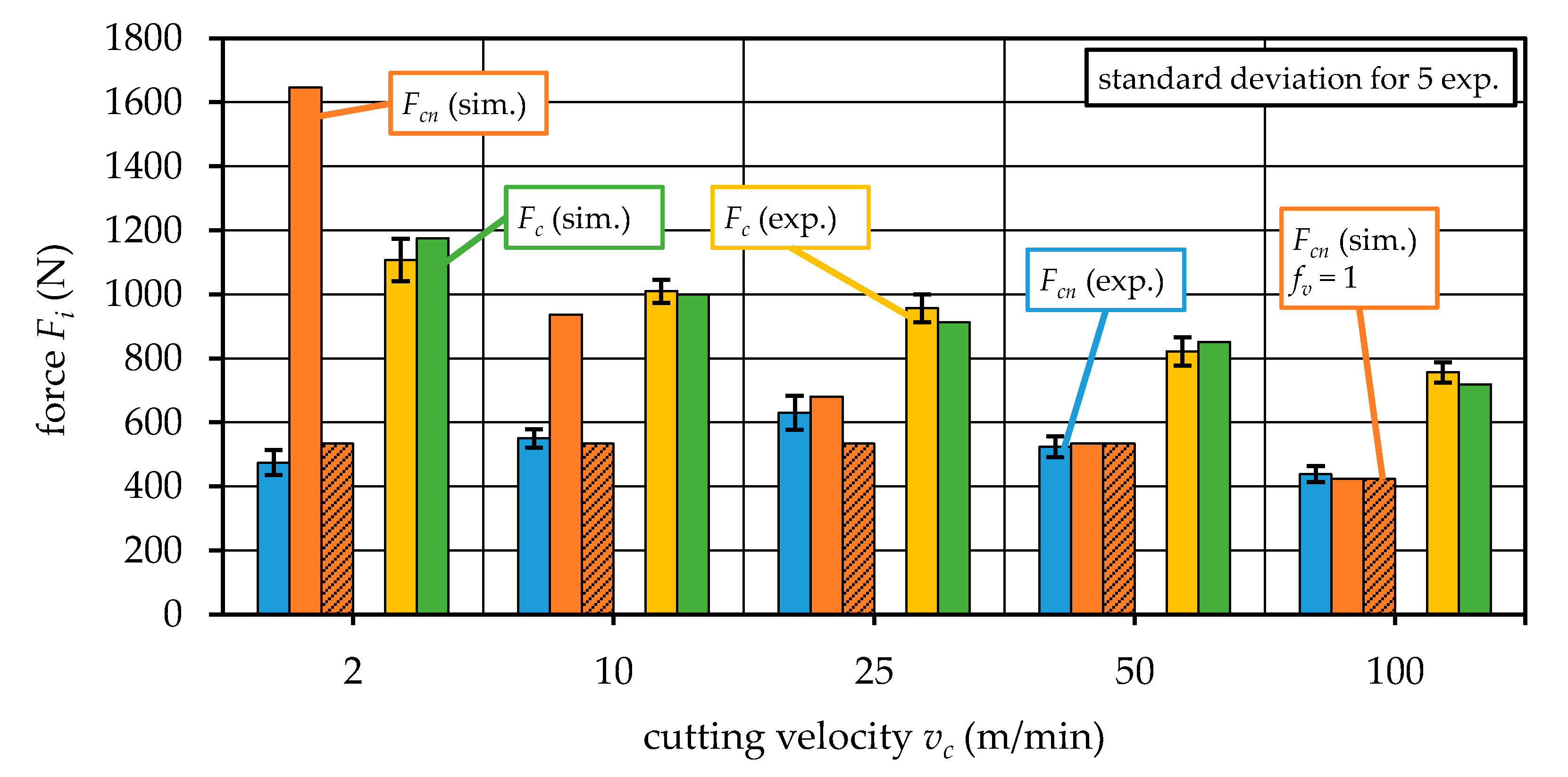
For the purpose of investigating the influence of a wide range of different orthogonal cutting processes and corresponding thermal numbers regarding the heat partition, own experiments were carried out as well. In this section, the resulting input parameters required for the thermal analysis are evaluated. Figure 4 shows the measured cutting and thrust forces. Additionally, simulated results based on the force model by Kienzle [38] and data from König and Essel [39] were obtained for the corresponding experiments to verify the model. The measured thrust forces initially increase up to a cutting velocity of vc = 25 m/min and subsequently decrease with a further rise of the cutting velocity. The measured cutting forces instead, decrease with further rise, as is expected. The simulated results are in good agreement within the standard deviation for the cutting forces. However, especially for the lowest thrust forces, the simulation highly overestimates the measured results. The reason can be found in the material specific data utilized in the force model. The available literature values of the specific thrust force unit kcn1.1 were obtained for cutting velocities of vc = 50 m/min and higher. According to Equation (13), the influence of the cutting velocity on the thrust force is considered by the correction factor fv. However, due to the high discrepancies for the two lowest investigated cutting velocities, the assumptions of the correction factor do not seem valid anymore. Thus, when the correction factor fv is neglected by setting its value to one, simulated thrust forces for the two lowest investigated cutting velocities became more reasonable, and also show good agreement within the standard deviation of the experimental values.
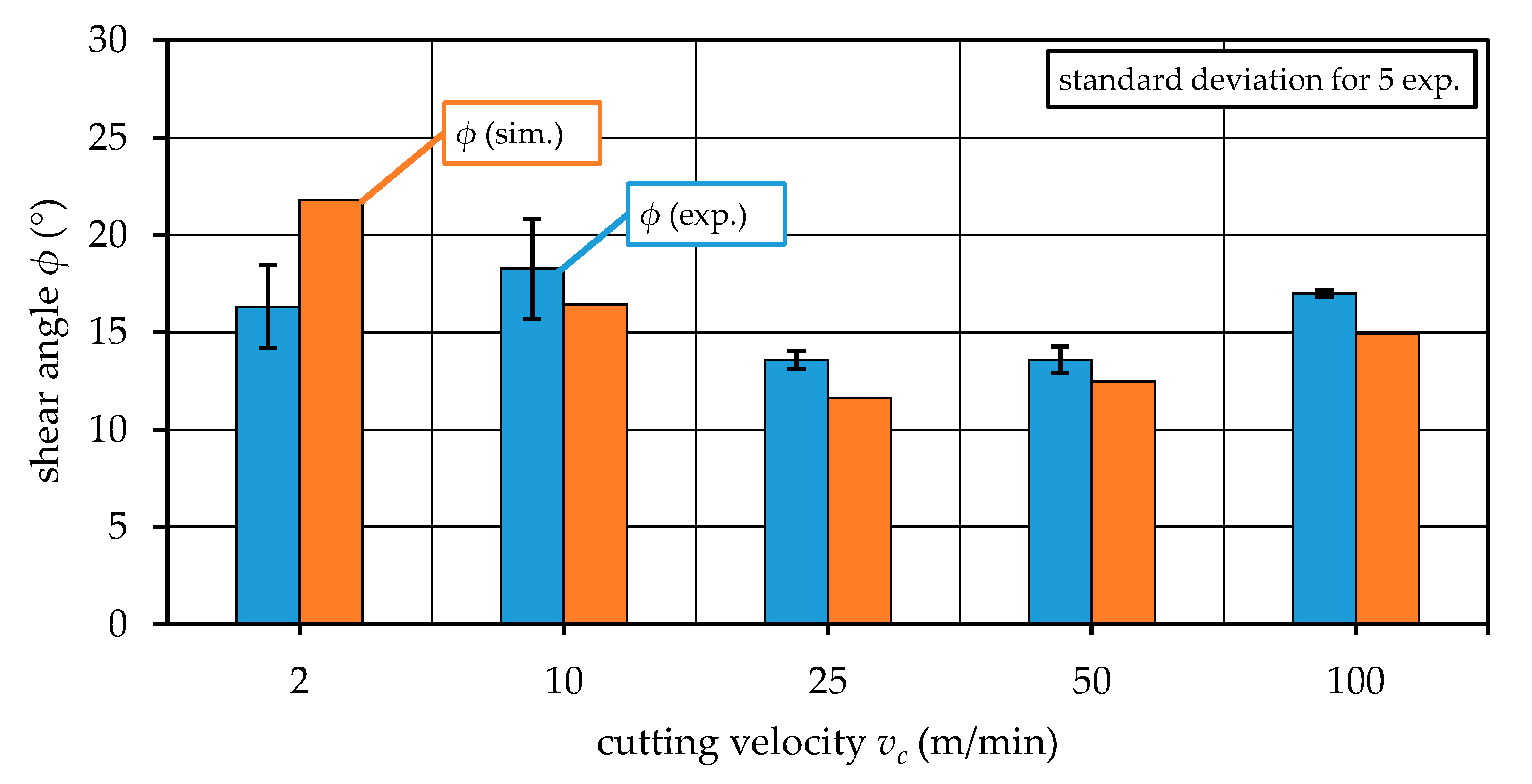
In Figure 5, the shear angles, determined based on experiments according to Equation (12), are shown. The values represent an average value of five experiments and vary in the range of 12° < ϕ < 17° for the investigated cutting velocities. Values of simulated shear angles are also shown, determined based on measured forces according to Equation (14), mostly indicating an underestimation of the simulation. However, in most cases, the simulated results lie within the experimental standard deviation when assuming a tolerance of 10% of the simulation results. Again, the value for the lowest cutting velocity stands out, and confirms the process as an extreme case.
In conclusion, the measured forces and shear angles show a satisfactorily low standard deviation throughout the series, and the utilized models were able to simulate results within this standard deviation when discrepancies to model assumptions are limited. For the thermal analysis on heat partition the measured values were used. Nevertheless, the simulation results encourage the idea of a purely model-based approach to generate various input parameters for thermal analysis. Thus, this idea was also realized for the two already mentioned materials AISI 4140 and EN 7075. The investigated machining parameters and resulting input parameters for this approach, as well as for all other utilized orthogonal cutting processes within the thermal analysis, are summarized in Table A1 in the Appendix A.

5.3. Comparison of Heat Partition by Weiner and Improved Komanduri and Hou

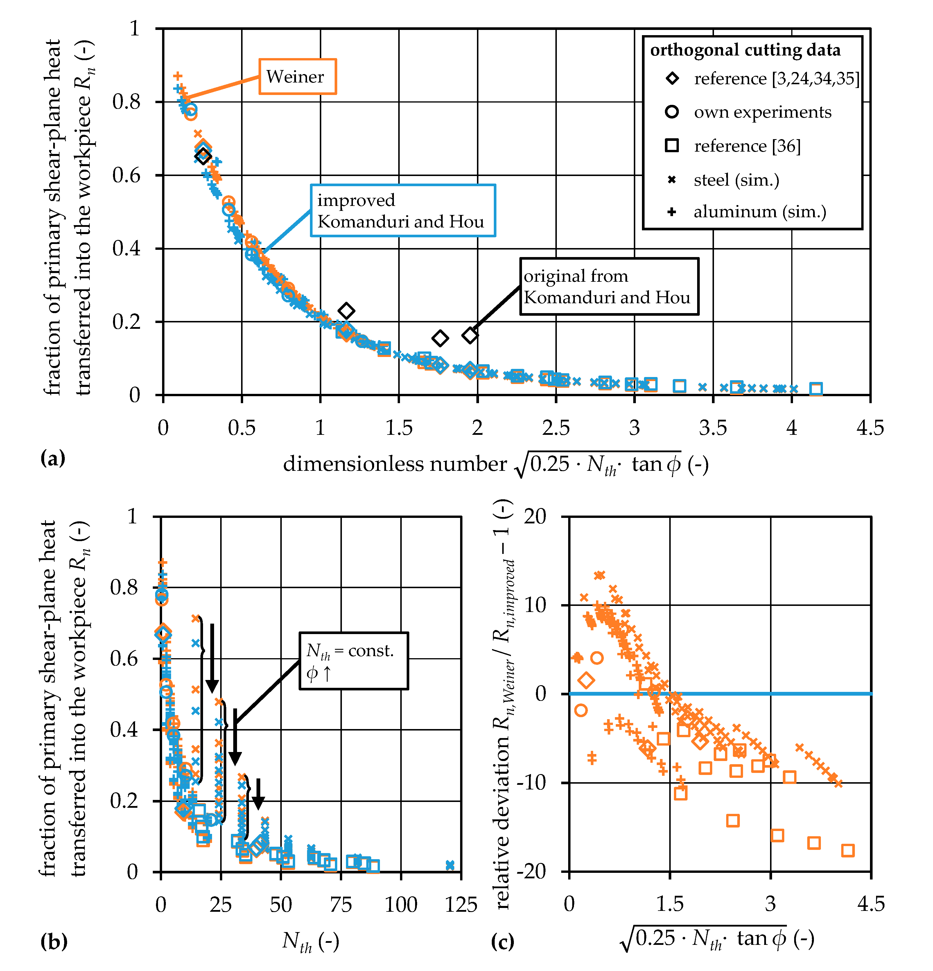
The orthogonal cutting data were used to calculate the fraction of primary shear plane heat transferred into the workpiece, and to investigate the influencing factors on heat partition. Figure 6b shows the fraction of heat based on the analytical models by Weiner and Komanduri and Hou plotted against the thermal number, as suggested by some researchers in the literature review. As already confirmed by Komanduri and Hou, in general, the fraction of heat transferred into the workpiece decreases with an increasing thermal number. This is despite the effect that the total shear power actually increases with increasing uncut chip thickness and cutting velocity, which, according to Equation (10), is based on increased forces with higher uncut chip thicknesses, and increased shear velocities compensating the thermal softening with higher cutting velocities. However, by increasing the uncut chip thickness the average distance of the shear plane to the level of the newly generated surface increases and, thus, the flow of generated heat into the workpiece is lower. The same is true for increasing the cutting velocity. Here, the reason is that the time for heat conduction is less, and more heat flow into the chip due to convection occurs. This effect is even more pronounced when the thermal diffusivity decreases. Thus, the thermal number is a reasonable quantity for the description of heat partition at the primary shear zone. However, Figure 6b also indicates that the heat partition does not solely depend on the thermal number, as different values of Rn exist for the same Nth. This becomes apparent because of the wide range of orthogonal cutting data utilized in the thermal analysis, among which some exemplary processes have the same thermal number Nth but different shear angles ϕ. An increase of the shear angle leads, again, to less time for heat transport by conduction and, thus, to a decreased fraction of heat transferred into the workpiece. This should be taken into account in a more general formulation of the heat partition at the primary shear zone. For this reason, heat partition was evaluated depending on the thermal number and the shear angle, according to Figure 6a. Therefore, the utilized term on the abscissa corresponds to the dimensionless number Y L , on which Weiner’s analytical solution for the fraction of heat transferred into the workpiece solely depends, and is used for further investigations on heat partition. It should be noted that Boothroyd’s approach using the thermal number Nth times the tangent of the shear angle ϕ is comparable. However, due to the above mentioned directly analytical representation, Weiner’s dimensionless number is used for further investigations. Utilizing this dimensionless number, all investigated fractions of heat arrange “themselves” along a “smooth” curve. This confirms the dependence on Weiner’s dimensionless number, and also validates the utilization of the purely model-based input parameters. The comparison of the originally values by Komanduri and Hou, and the values obtained with the developed improved evaluation again indicate the relevant discrepancies. Furthermore, by utilizing the improved evaluation, the fraction of heat is clearly changed towards the results simulated with Weiner’s approach. For the detailed comparison of both analytical approaches the relative deviation is shown in Figure 6c. For most of the investigated data the relative deviations of Weiner’s results lie within a range of ±10%, compared to the improved results based on Komanduri and Hou. However, taking into account the absolute deviations, discrepancies between these two models seem to be irrelevant for dimensionless numbers Y L higher than one. With lower dimensionless numbers Weiner’s results increase in relation to the improved results based on Komanduri and Hou. This indicates that, with increasing relevancy of heat conduction, the discrepancies become higher, which is reasonable when the different model assumptions are considered. In conclusion, research question 2 is to be answered in the affirmative, and the fraction of primary shear plane heat transferred into the workpiece does depend on the shear angle, in addition to the thermal number.

5.4. Investigation on Additional Influencing Factors on Heat Partition

In a first investigation on additional influencing factors on the fraction of shear plane heat transferred into the workpiece, deviations between the improved model based on Komanduri and Hou and the three developed numerical models shown in Figure 2 were evaluated. In Figure 7, temperature fields calculated by means of these modeling approaches are presented. Exemplarily, orthogonal cutting data provided by Boothroyd and Knight [24] have therefore been utilized. It becomes apparent that temperature fields simulated by finite-element model A are very similar to the analytical results from Komanduri and Hou. This is true for the workpiece, but also for the imaginary chip part. The additional adiabatic boundary at the newly generated surface in finite-element model B results in lower workpiece temperatures behind the shear plane, as indicated in Figure 7c. This is reasonable, due to the missing possibility of heat transport by conduction from the imaginary chip side into the workpiece. Considering a chip flow in the direction of the chip velocity according to Figure 7d and the finite-element model C influences the temperature field in the chip, but has only a minor effect on the workpiece temperatures. For the evaluation of results on heat partition, the temperature fields were utilized to calculate the heat flow into the workpiece.
Table 6 lists the fractions of heat transferred into the workpiece based on results from the improved Komanduri and Hou model, and the deviations to the finite-element models for four different orthogonal cutting processes. With relative deviations not higher than 3.30%, the direct numerically representation of Komanduri and Hou’s model in the finite-element model A seems reasonable for all dimensionless numbers Y L . By implementing an adiabatic boundary at the newly generated workpiece surface in finite-element model B, the fraction of heat transferred into the workpiece decreases, as expected, but the deviations are quite low, and the boundary condition seems to be negligible. In finite-element model C the chip specifics were considered, i.e., the geometry and a mass flow rate corresponding to the chip velocity. The heat transferred into the workpiece slightly increases compared to results from finite-element model B for all but one orthogonal cutting process. Due to the fact that the chip velocity is lower than the cutting velocity for all cases and, thus, the heat transport by convection in the chip is lower in finite-element model C, this is reasonable. Nevertheless, again, the low deviations indicate an irrelevant influence.
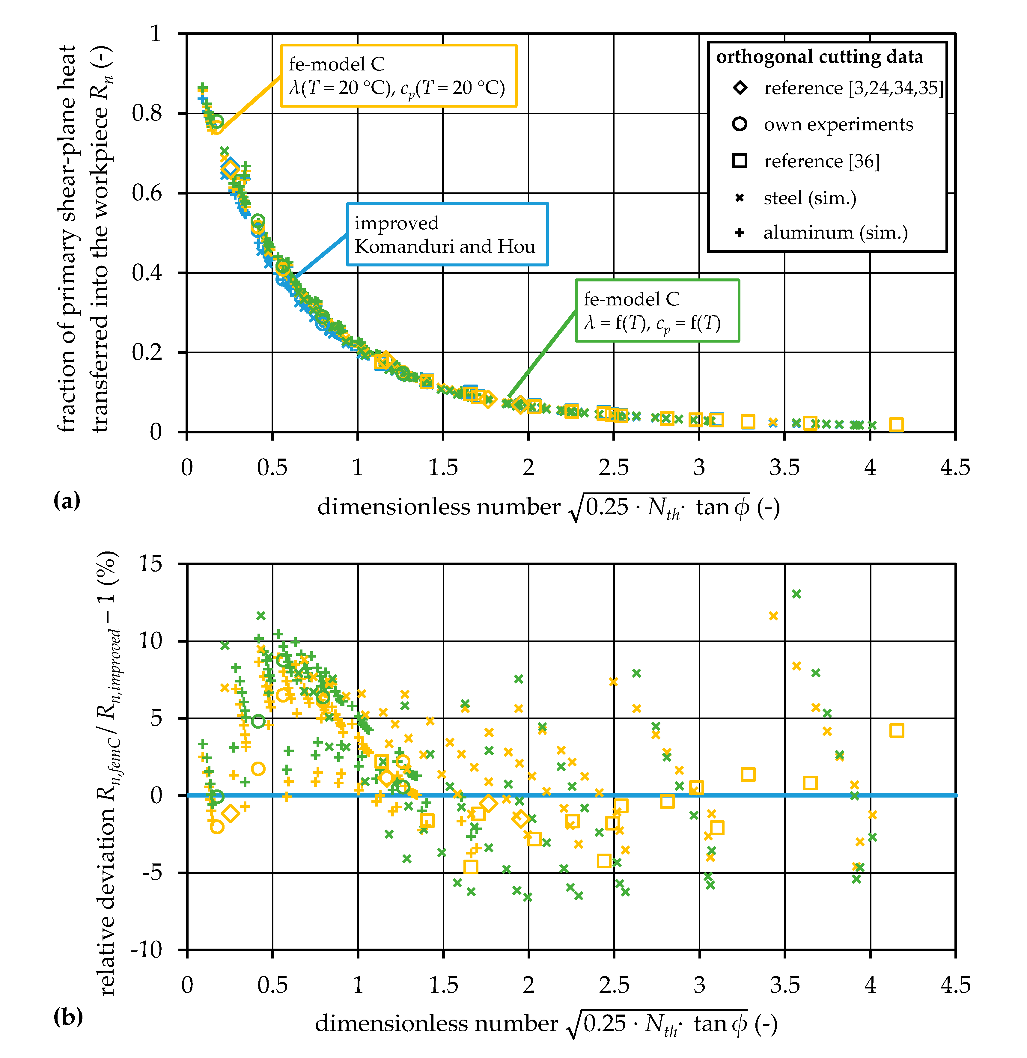
The finite-element model C (additional chip flow) is further utilized to determine the influence of temperature-dependent material properties. Figure 8 shows the fractions of heat transferred into the workpiece and their deviations over the previously introduced dimensionless number Y L for temperature-dependent and room temperature numerical results, and results based on Komanduri and Hou for room temperature. It should be noted that the density was kept temperature-independent, due to the direct connection to the mass flow rate and no possibility in the simulation environment for an iterative solution of a temperature-dependent mass flow rate. This seems to be an acceptable assumption since in the resulting temperature range, the density does not change significantly for the investigated materials. Nevertheless, temperature-dependent thermal conductivity and specific heat capacity were implemented in the finite-element model, and the specific heat capacity was also taken into account as temperature-dependent for the evaluation, resulting in solving the integral in Equation (9) numerically with multipoint linear regression of the specific heat capacity. No significant changes due to the temperature dependency can be observed regarding the fraction of heat transferred into the workpiece. In fact, the relative deviation of the temperature-dependent results in relation to the independent results obtained from finite-element model C lie in a range of ±5%. Similar relative deviations were found by comparing the results from finite-element model C and the improved Komanduri and Hou model, considering no temperature dependency. Thus, it can be concluded that none of the investigated influencing factors have a significant impact on the heat partition at the primary shear zone. It is worth mentioning that, by comparing the relative deviations of the finite-element model C with deviations from Weiner’s model in Figure 6, for dimensionless numbers Y L lower than one, Weiner’s model calculates the fraction of heat transferred into the workpiece with great agreement. In conclusion, research question 3 is to be answered in the negative, and the considered further adjustments to reality, implemented in numerical models, do not have a relevant influence on the heat partition.

5.5. Comparison with Measurements

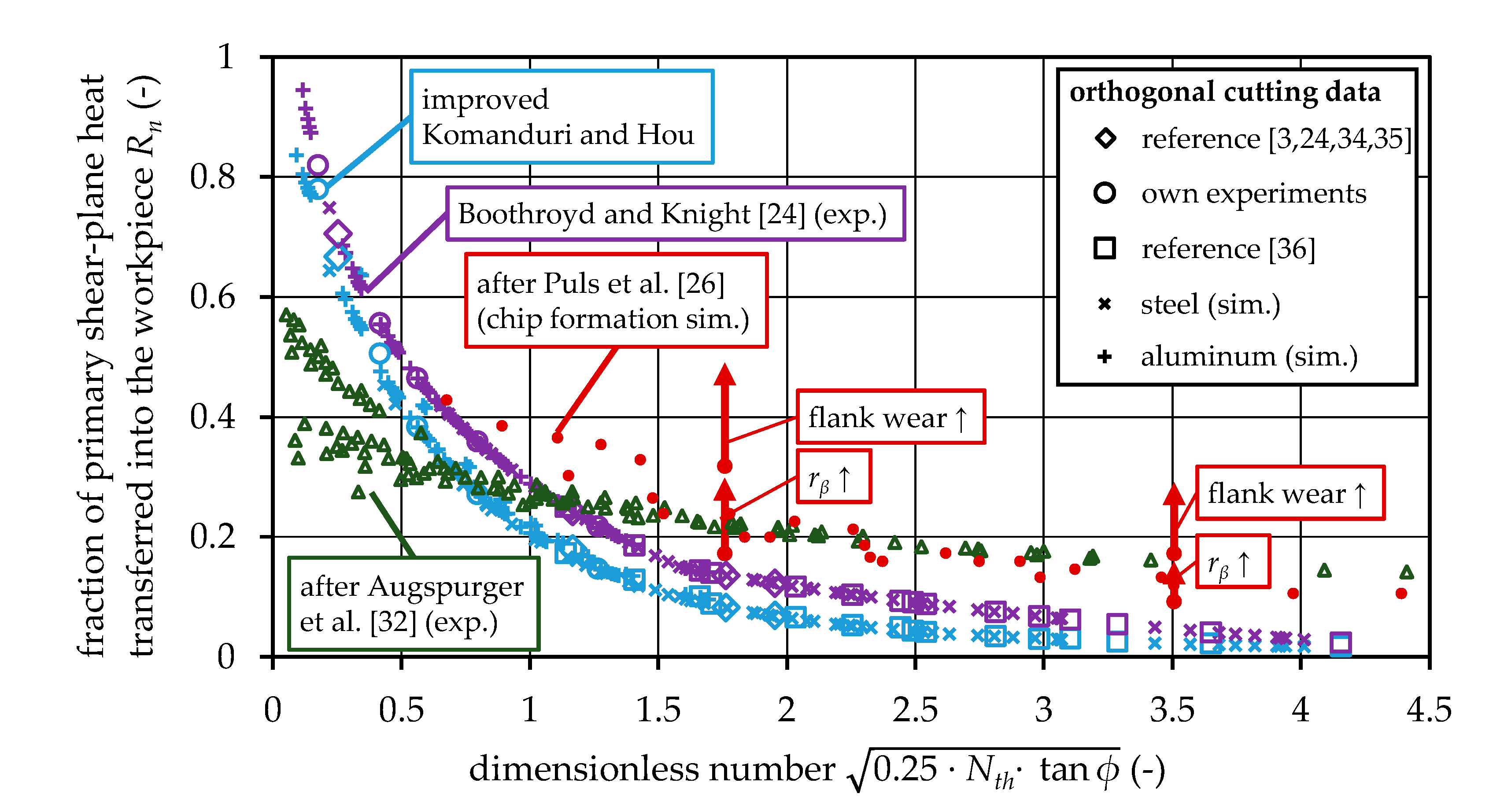
The investigated analytical and numerical models were also evaluated in comparison to fractions of heat transferred into the workpiece based on measurements according to the literature review. As the deviations between the utilized models were determined to be small, the results of the improved calculation of Komanduri and Hou’s model represent the simulation approaches in this comparison. Regarding measurement-based results, the early works by Boothroyd were taken into account by calculating the fraction of shear plane heat transferred into the workpiece for the investigated orthogonal cutting processes by means of the provided regression equation in Boothroyd and Knight’s publication [24]. Furthermore, the recently conducted comprehensive study by Augspurger et al. [32] is also considered. The provided regression equation by Augspurger et al. solely depends on the thermal number, and does not describe the fraction of shear plane heat, but the fraction of the total cutting energy transferred into the workpiece. Thus, for comparison with simulated data, the regression equation had to be further processed. Initially, the cutting and thrust forces for the experiments conducted in their study were determined based on the force model by Kienzle [38] and corresponding input data from König and Essel [39] for the four workpiece materials. According to the approach already successfully realized for the determination of purely model-based input parameters for the thermal analysis, based on the cutting and thrust forces, the shear angle, the total shear power, and the fraction of total shear power in relation to the total cutting power were calculated. The fraction of shear plane heat transferred into the workpiece was then determined by multiplying the results from the regression equation and the reciprocal of the fraction of total shear power in relation to the total cutting power. Figure 9 shows the results of the regression equation by Boothroyd and Knight, and the further processed data based on the regression equation by Augspurger et al., in comparison to the improved calculation of Komanduri and Hou’s model. Boothroyd and Knight’s results show a similar characteristic compared to the simulation results. As already found in the early work by Boothroyd [28] when comparing his experiments with Weiner’s equation, the models tend to underestimate the fraction of heat transferred into the workpiece. This is also true, and to a much larger extent for experimental-based results from Augspurger et al. for dimensionless numbers Y L higher than one. However, while the characteristic of Boothroyd and Knight’s results are similar to the analytical model, the characteristic of these results is different. For the higher fraction of shear plane heat transferred into the workpiece for dimensionless numbers above one, the following reason Boothroyd also gave in his early work seems reasonable. In the modeling approaches a plane heat source at the shear plane is assumed and heat transport into the workpiece can only be realized by conduction. However, due to a cutting edge radius instead of a perfectly sharp tool and strain-rate dependent material properties in the shear zone, in reality, the primary deformation zone extends into the workpiece. Thus, in addition to heat transport by conduction convection into the workpiece also occurs. This effect becomes higher with an increasing thermal number, because convection dominates the heat transport. In correspondence to this effect, in reality, friction at the flank face of the tool cannot be completely neglected, even when wear is controlled. The frictional heat is almost completely induced into the workpiece because it is generated behind the shear zone and conduction into the chip is negligible. Furthermore, this heat will also increase with increased cutting velocity, according to tribology knowledge. In conclusion, for dimensionless numbers above one, the deviation between the measurement and the simulation might be explained by the extension of the shear zone, the existing cutting edge radius, and the friction at the flank face of the tool. For confirmation of this statement, chip formation simulations by Puls et al. [26] were further processed in the already described way to give information on the fraction of shear plane heat transferred into the workpiece. As indicated in Figure 9, Puls et al. also varied the cutting edge radius rβ and the flank wear within the simulation approach, and the results clearly support the described influence on the heat partition. Puls et al. did not provide data for low dimensionless numbers, and it cannot be argued whether their chip formation simulation follows the trend from the experimental-based results by Augspurger et al. for low dimensionless numbers. Two reasons might be relevant to explain the deviations for dimensionless numbers below one. First, the calculation of the fraction of heat transferred into the workpiece utilized in the study by Augspurger et al. might be erroneous for these processes. In their approach, the fraction of heat is based on the average temperature calculated from measured temperature fields on a surface by an infrared camera before and after the cut. Considering decreasing dimensionless numbers, these measurements become more and more complicated. This is due to a narrower heated zone under the workpiece surface because of low uncut chip thicknesses, and especially due to higher process times with low cutting velocities. According to Augspurger et al., the experiments were conducted in a way that heat flow in normal direction to the workpiece can be neglected. However, with increasing process time, heat transport by conduction becomes dominant, and may lead to relevant not detected heat losses in this direction. As pointed out by Augspurger et al., measuring the temperature field during the process does not seem to be a reasonable solution, because of the highly challenging measurement of fields with large temperature differences occurring between chip and workpiece. The second reason for lower fractions of heat for low dimensionless numbers might be the processing of the original data to obtain the shear power and the shear angle. It was shown for the own experiments that the utilized models’ accuracies become lower for processes with extreme machining parameters. Thus, experimentally validated input parameters for the processes investigated by Augspurger et al. and also Puls et al. would be highly valuable. This might also be the reason why the regression equation by Boothroyd and Knight show a better agreement to the modeling approaches. In conclusion, research question 4 is to be answered in the affirmative, and the idealized conditions in the utilized models do have a relevant influence on heat partition in comparison to experimental-based results. For heat partition in industry relevant processes, e.g., milling and drilling, investigations have to clarify if these deviations are still relevant for the fraction of shear plane heat transferred into the workpiece.

6. Conclusions

The objective of the present work was the investigation of influencing factors on the fraction of shear plane heat transferred into the workpiece in orthogonal metal cutting. It could be shown that the heat partition does not solely depend on the cutting velocity, the uncut chip thickness, and the thermal diffusivity—combined in the thermal number—but the shear angle also has to be taken into account. This finding is supported for all investigated orthogonal cutting processes, including own experiments, and purely model-based data considered in the thermal analysis by means of the analytical models by Weiner and Komanduri and Hou. For the first time, it could be demonstrated that these models, although considering different assumptions, lead to comparable results. This was mainly achieved by improving the evaluation of heat flow in the approach by Komanduri and Hou. Furthermore, developed numerical models show that a more realistic representation of the process kinematics, e.g., regarding chip flow, and temperature-dependent material properties do not have a relevant impact on the heat partition. Nevertheless, the models still assume an idealized orthogonal cutting process, and a comparison to experimental-based findings on heat partition indicate a significant influence of the cutting edge radius and the friction on the flank face of the tool. The first is also accompanied by the assumption that the shear plane utilized in the models is actually a shear zone. However, measured and simulated fractions of shear plane heat transferred into the workpiece still show the same characteristic. In future, the significance of the remaining deviations for machining processes as milling and drilling should be investigated, and the question should be answered whether the heat partition for these industry relevant processes is probably dominated by other effects, e.g., the removal of heat due to subsequent cutting edge engagements. For investigations in this direction, the present work supports that it seems reasonable to approximate the heat partition in the shear zone by the direct analytical solution by Weiner.

Author Contributions

Conceptualization, all authors; methodology, L.L. and S.K.; software, L.L. and S.K.; validation, L.L.; formal analysis, L.L.; investigation, L.L.; resources, J.S.; data curation, L.L.; writing—original draft preparation, L.L. and S.K.; writing—review and editing, L.L. and J.S.; visualization, L.L.; supervision, J.S.; project administration, J.S.; funding acquisition, J.S.; All authors have read and agreed to the published version of the manuscript.

Funding

This research and the APC was funded by the Deutsche Forschungsgemeinschaft (DFG, German Research Foundation), grant number SO 1236/2-1.

Conflicts of Interest

The authors declare no conflict of interest.

Nomenclature

SymbolQuantity
athermal diffusivity
cpspecific isobaric heat capacity
cvspecific isochoric heat capacity
erferror function
erfccomplementary error function
Fccutting force
Fcnthrust force
Fsshear force
huncut chip thickness
hchchip thickness
K0modified Bessel function of second kind of zero order
Llength of shear plane
lcuncut chip length
lchchip length
mmass
mchchip weight
m . mass flow rate
m . ch mass flow rate in the chip
m . wp mass flow rate in the workpiece
Nththermal number
nXtotal amount of elements in X-direction
nZtotal amount of elements in Z-direction
pfriction angle
Pstotal shear power
q . s shear plane heat flux density
Qheat
Q . ch heat flow rate into the chip
Q . total total heat flow rate
Q . wp heat flow rate into the workpiece
r2coefficient of determination
RAugspurgerfraction of total cutting power transferred into the workpiece from Augspurger
Rnfraction of shear plane heat transferred into the workpiece
rβcutting edge radius
sdistance along shear plane
Δttime period
Ttemperature
ΔTtemperature rise
Δ T ch ¯ mean temperature rise in the chip
ΔTMtemperature rise in point M(X,Z) in Komanduri and Hou’s model
toltolerance of temperature differences
vvelocity
vccutting velocity
vchchip velocity
vsshear velocity
Vvolume
wwidth
Δxdistance of grid points in X-direction
YLauxiliary variable in Weiner’s model
Δzdistance of grid points in Z-direction
γrake angle
λthermal conductivity
λlchip length ratio
ρdensity
φauxiliary angle in Komanduri and Hou’s model
ϕshear angle

Appendix A

Table A1. Summary of all utilized input parameters for the thermal analysis on heat partition.
SourceNthh (µm)vc (m/min)ϕ (°) q . s (W/mm2) SourceNthh (µm)vc (m/min)ϕ (°) q . s (W/mm2)
[3]9.460.0139.230.11182.9sim.10.190.8450.030.83735.2
[24]41.5250.0120.016.7634.4sim.13.2213.6250.018.61136.0
[33]39.7248.991.421.011167.5sim.13.21068.150.015.7174.0
[34]0.910.0517.815.52399.9sim.13.2534.1100.017.0392.0
[35]16.0258.850.018.0452.2sim.13.2356.0150.017.7628.5
[35]17.0258.850.025.0595.2sim.13.2267.0200.018.2877.5
[35]17.7258.850.032.0588.4sim.13.2178.0300.018.91402.3
[35]31.9258.8100.020.0948.5sim.13.289.0600.025.14012.0
[35]33.9258.8100.026.01140.3sim.13.2152.6350.029.82554.1
[35]35.3258.8100.034.01172.9sim.13.2118.7450.030.83506.3
[35]47.9258.8150.023.01564.2sim.14.562.8150.02.9373.5
[35]50.9258.8150.026.01728.1sim.14.547.1200.00.8138.0
[35]53.0258.8150.036.01755.5sim.14.594.2100.07.4632.0
[35]63.9258.8200.022.02076.1sim.14.5188.550.010.8432.8
[35]67.8258.8200.025.02204.0sim.19.4523.6150.019.3634.7
[35]70.7258.8200.037.02421.1sim.19.4261.8300.020.41407.3
[35]79.9258.8250.024.02827.2sim.19.4130.9600.028.04062.2
[35]84.8258.8250.027.02829.7sim.19.4224.4350.029.72331.6
[35]88.4258.8250.038.02876.5sim.19.41570.850.017.4177.9
exp.0.4120.02.016.336.1sim.19.4785.4100.018.6397.5
exp.2.1120.010.018.3171.1sim.19.4392.7200.019.8883.8
exp.5.2120.025.013.6316.1sim.19.4314.2250.020.11141.9
exp.10.4120.050.013.6545.4sim.19.4174.5450.030.73201.6
exp.20.9120.0100.017.01202.4sim.24.134.9450.02.2824.5
sim.0.862.850.02.551.1sim.24.144.9350.04.01148.3
sim.0.831.4100.04.0168.6sim.24.152.4300.05.21230.1
sim.0.820.9150.04.8313.7sim.24.162.8250.06.51252.0
sim.0.815.7200.05.4477.3sim.24.1104.7150.010.21085.8
sim.0.812.6250.05.9654.9sim.24.178.5200.08.21207.1
sim.0.810.5300.06.3844.1sim.24.1157.1100.013.1925.9
sim.0.89.0350.030.64986.1sim.24.1314.250.015.4506.0
sim.0.87.0450.031.56832.5sim.33.736.7600.04.92317.2
sim.2.315.7600.07.22007.6sim.33.773.3300.010.02104.3
sim.2.362.8150.010.1511.4sim.33.7146.6150.014.71417.1
sim.2.331.4300.011.51206.7sim.33.748.9450.07.02372.6
sim.2.3188.550.07.8125.3sim.33.762.8350.08.92234.2
sim.2.394.2100.09.3306.7sim.33.788.0250.011.31928.9
sim.2.347.1200.010.7731.9sim.33.7110.0200.012.81702.4
sim.2.337.7250.011.2964.4sim.33.7219.9100.016.51049.2
sim.2.326.9350.030.33847.5sim.33.7439.850.018.2529.8
sim.2.320.9450.031.25276.0sim.43.480.8350.012.32871.7
sim.3.9104.7150.012.5565.0sim.43.447.1600.08.53674.8
sim.3.926.2600.013.23036.5sim.43.494.2300.013.42618.3
sim.3.962.8250.013.51046.1sim.43.4188.5150.017.91612.4
sim.3.952.4300.013.81301.3sim.43.462.8450.010.63278.9
sim.3.944.9350.030.13410.4sim.43.4113.1250.014.62327.4
sim.3.934.9450.031.14678.1sim.43.4141.4200.016.01994.3
sim.3.9314.250.010.3146.4sim.43.4282.7100.019.01114.1
sim.3.9157.1100.011.7344.8sim.43.4565.550.020.1538.4
sim.3.978.5200.013.0799.9sim.53.057.6600.011.34575.8
sim.5.4146.6150.014.0590.5sim.53.076.8450.013.33881.7
sim.5.473.3300.015.31344.6sim.53.0115.2300.015.92960.6
sim.5.436.7600.016.93469.5sim.53.0230.4150.020.21742.1
sim.5.4439.850.011.8156.8sim.53.098.7350.014.93296.2
sim.5.4219.9100.013.2363.2sim.53.0138.2250.017.12592.8
sim.5.4110.0200.014.5831.8sim.53.0172.8200.018.52188.5
sim.5.488.0250.014.91083.8sim.53.0345.6100.020.81152.3
sim.5.462.8350.030.13149.9sim.53.0691.250.021.6540.6
sim.5.448.9450.031.04321.7sim.62.668.1600.013.55222.8
sim.7.080.8350.030.02968.3sim.62.6116.7350.017.03601.1
sim.7.0565.550.013.0163.1sim.62.6136.1300.018.03206.4
sim.7.0282.7100.014.3374.1sim.62.6204.2200.020.42327.5
sim.7.0188.5150.015.1605.2sim.62.6272.3150.022.01834.5
sim.7.0141.4200.015.6849.9sim.62.6408.4100.022.31176.1
sim.7.0113.1250.016.01105.0sim.62.6816.850.022.8539.8
sim.7.094.2300.016.41368.5sim.62.690.8450.015.44314.8
sim.7.047.1600.019.43698.9sim.62.6163.4250.019.12783.1
sim.7.062.8450.030.94073.3sim.81.9213.6250.022.13038.3
sim.8.5230.4150.015.9614.5sim.81.989.0600.016.96096.7
sim.8.5115.2300.017.21383.0sim.81.9118.7450.018.74899.3
sim.8.557.6600.021.33834.7sim.81.9152.6350.020.24011.8
sim.8.576.8450.030.93885.2sim.81.9178.0300.021.13536.9
sim.8.5691.250.013.9167.2sim.81.9267.0200.023.22513.0
sim.8.5345.6100.015.2381.1sim.81.9534.1100.024.41201.1
sim.8.5172.8200.016.5861.2sim.81.91068.150.024.6534.3
sim.8.5138.2250.016.91118.0sim.81.9356.0150.024.71956.8
sim.8.598.7350.029.92830.9sim.120.4130.9600.021.47061.5
sim.10.1816.850.014.6170.2sim.120.4224.4350.024.24459.4
sim.10.1408.4100.015.9385.9sim.120.4261.8300.025.03894.9
sim.10.1272.3150.016.6620.9sim.120.4523.6150.028.12084.1
sim.10.1204.2200.017.1868.8sim.120.4174.5450.022.95540.9
sim.10.1136.1300.017.91392.3sim.120.4314.2250.025.93312.5
sim.10.168.1600.022.83920.2sim.120.4392.7200.026.92709.9
sim.10.1116.7350.029.92721.3sim.120.41570.850.027.0519.3
sim.10.1163.4250.017.51126.5sim.120.4785.4100.027.31213.6

References

  1. Kuschel, S.; Kolkwitz, B.; Sölter, J.; Brinksmeier, E.; Heinzel, C. Experimental and numerical analysis of residual stress change caused by thermal loads during grinding. Procedia CIRP 2016, 45, 51–54. [Google Scholar] [CrossRef] [Green Version]
  2. Novovic, D.; Aspinwall, D.K.; Dewes, R.C.; Bowen, P.; Griffiths, B. The effect of surface and subsurface condition on the fatigue life of Ti–25V–15Cr–2Al–0.2C %wt alloy. CIRP Ann. 2016, 65, 523–528. [Google Scholar] [CrossRef]
  3. Shaw, M.C. Metal Cutting Principles, 2nd ed.; Oxford University Press: New York, NY, USA, 2005; ISBN 0195142063. [Google Scholar]
  4. Segurajauregui, U.; Arrazola, P.J. Heat-flow determination through inverse identification in drilling of aluminium workpieces with MQL. Prod. Eng. Res. Dev. 2015, 9, 517–526. [Google Scholar] [CrossRef]
  5. Fleischer, J.; Pabst, R.; Kelemen, S. Heat flow simulation for dry machining of power train castings. CIRP Ann. 2007, 56, 117–122. [Google Scholar] [CrossRef]
  6. Sölter, J.; Frohmüller, R.; Wirbser, H. Temperature measurements and heat partitioning in machining processes. In Thermal Effects in Complex Machining Processes: Final Report of the DFG Priority Programme 1480: Lecture Notes in Production Engineering; Biermann, D., Hollmann, F., Eds.; Springer Internat. Publ: Cham, Switzerland, 2018; pp. 5–21. ISBN 978-3-319-57120-1. [Google Scholar]
  7. Langenhorst, L.; Cihan, M.; Sölter, J. A three dimensional calculation approach for the heat flux density distribution in face milling. Procedia CIRP 2019, 82, 8–13. [Google Scholar] [CrossRef]
  8. Merchant, M.E. Mechanics of the metal cutting process. I. Orthogonal cutting and a type 2 chip. J. Appl. Phys. 1945, 16, 267–275. [Google Scholar] [CrossRef]
  9. Jaeger, J.C. Moving sources of heat and the temperature of sliding contacts. Proc. R. Soc. N. S. W. 1942, 76, 203–224. [Google Scholar]
  10. Loewen, E.G.; Shaw, M.C. On the analysis of cutting tool temperatures. Trans. ASME 1954, 71, 217–231. [Google Scholar]
  11. Grzesik, W.; Nieslony, P. Physics based modelling of interface temperatures in machining with multilayer coated tools at moderate cutting speeds. Int. J. Mach. Tools Manuf. 2004, 44, 889–901. [Google Scholar] [CrossRef]
  12. Sölter, J.; Gulpak, M. Heat partitioning in dry milling of steel. CIRP Ann. 2012, 61, 87–90. [Google Scholar] [CrossRef]
  13. Malkin, S.; Guo, C. Thermal analysis of grinding. CIRP Ann. 2007, 56, 760–782. [Google Scholar] [CrossRef]
  14. Hahn, R.S. On the temperature developed at the shear plane in the metal cutting process. In Proceedings of the First U.S. National Congress of Applied Mechanics, Chicago, IL, USA, 11–16 June 1951; pp. 661–666. [Google Scholar]
  15. Komanduri, R.; Hou, Z.B. Thermal modeling of the metal cutting process Part I—Temperature rise distribution due to shear plane heat source. Int. J. Mech. Sci. 2000, 42, 1715–1752. [Google Scholar] [CrossRef]
  16. Chao, B.T.; Trigger, K.J. The significance of thermal number in metal machining. Trans. ASME 1953, 75, 109–120. [Google Scholar]
  17. Komanduri, R.; Hou, Z.B. Thermal modeling of the metal cutting process—Part II: Temperature rise distribution due to frictional heat source at the tool-chip interface. Int. J. Mech. Sci. 2001, 43, 57–88. [Google Scholar] [CrossRef]
  18. Komanduri, R.; Hou, Z.B. Thermal modeling of the metal cutting process—Part III: Temperature rise distribution due to the combined effects of shear plane heat source and the tool-chip interface frictional heat source. Int. J. Mech. Sci. 2001, 43, 89–107. [Google Scholar] [CrossRef]
  19. Karpat, Y.; Özel, T. Predictive analytical and thermal modeling of orthogonal cutting process—part i: Predictions of tool forces, stresses, and temperature distributions. J. Manuf. Sci. Eng. 2006, 128, 435–444. [Google Scholar] [CrossRef]
  20. Grzesik, W. Heat in metal cutting. In Advanced Machining Processes of Metallic Materials: Theory, Modelling and Applications, 2nd eds.; Grzesik, W., Ed.; Elsevier: Oxford, UK; Boston, MA, USA, 2017; pp. 163–182. ISBN 9780444637116. [Google Scholar] [CrossRef]
  21. Akbar, F.; Mativenga, P.T.; Sheikh, M.A. Prediction of heat partition in metal cutting: A State-of-the-art Review of conventional to high-speed machining. In Metal cutting: Research Advances; Davim, J.P., Ed.; Nova Science Publishers: New York, NY, USA, 2010; pp. 23–75. ISBN 978-1-60876-207-1. [Google Scholar]
  22. Deshpande, A.; Madhavan, V. Study of heat partition at the primary shear plane using finite element analysis of heat and mass transfer. In Transactions of the North American Manufacturing Research Institution of SME; Society of Manufacturing Engineers: Dearborn, MI, USA, 2007; Volume 35. [Google Scholar]
  23. Xia, Q.; Gillespie, D.R.H. Quasi-static finite element modelling of thermal distribution and heat partitioning for the multi-component system of high speed metal cutting. J. Mater. Proc. Technol. 2020, 275, 116389. [Google Scholar] [CrossRef]
  24. Boothroyd, G.; Knight, W.A. Fundamentals of Machining and Machine Tools, 3rd ed.; CRC Taylor & Francis: Boca Raton, FL, USA, 2006; ISBN 9781574446593. [Google Scholar]
  25. Arrazola, P.J.; Özel, T.; Umbrello, D.; Davies, M.A.; Jawahir, I.S. Recent advances in modelling of metal machining processes. CIRP Ann. 2013, 62, 695–718. [Google Scholar] [CrossRef]
  26. Puls, H.; Klocke, F.; Veselovac, D. FEM-based prediction of heat partition in dry metal cutting of AISI 1045. Int. J. Adv. Manuf. Technol. 2016, 86, 737–745. [Google Scholar] [CrossRef]
  27. Davies, M.A.; Ueda, T.; M’Saoubi, R.; Mullany, B.; Cooke, A.L. On the measurement of temperature in material removal processes. CIRP Ann. 2007, 56, 581–604. [Google Scholar] [CrossRef]
  28. Boothroyd, G. Temperatures in orthogonal metal cutting. Proc. Inst. Mech. Eng. 1963, 177, 789–810. [Google Scholar] [CrossRef]
  29. Lazoglu, I.; Altintas, Y. Prediction of tool and chip temperature in continuous and interrupted machining. Int. J. Mach. Tools Manuf. 2002, 42, 1011–1022. [Google Scholar] [CrossRef]
  30. Ulutan, D.; Erdem Alaca, B.; Lazoglu, I. Analytical modelling of residual stresses in machining. J. Mater. Process. Technol. 2007, 183, 77–87. [Google Scholar] [CrossRef]
  31. Lazoglu, I.; Bugdayci, B. Thermal modelling of end milling. CIRP Ann. 2014, 63, 113–116. [Google Scholar] [CrossRef]
  32. Augspurger, T.; Bergs, T.; Döbbeler, B. Measurement and modeling of heat partitions and temperature fields in the workpiece for cutting inconel 718, AISI 1045, Ti6Al4V, and AlMgSi0.5. J. Manuf. Sci. Eng. 2019, 141, 061007. [Google Scholar] [CrossRef]
  33. Weiner, J.H. Shear-plane temperature distribution in orthogonal cutting. Trans. ASME 1955, 77, 1331–1341. [Google Scholar]
  34. Trigger, K.J.; Chao, B.T. An analytical evaluation of metal cutting temperature. Trans. ASME 1951, 73, 58–68. [Google Scholar]
  35. Ueda, T. Cutting temperature. In CIRP Encyclopedia of Production Engineering; Laperrière, L., Reinhart, G., Eds.; Springer: Berlin, Germany, 2014; pp. 334–345. ISBN 978-3-642-20616-0. [Google Scholar]
  36. Childs, T.H.C.; Rahmad, R. Modelling orthogonal machining of carbon steels. Part II: Comparisons with experiments. Int. J. Mech. Sci. 2009, 51, 465–472. [Google Scholar] [CrossRef]
  37. Spittel, M.; Spittel, T. Steel symbol/number: 100Cr6/1.3505. In Numerical Data and Functional Relationships in Science and Technology: New Series; Spittel, M., Spittel, T., Warlimont, H., Landolt, H., Börnstein, R., Martienssen, W., Eds.; Springer: Berlin, Germany, 2009; pp. 552–557. ISBN 978-3-540-44758-0. [Google Scholar]
  38. Kienzle, O. Die Bestimmung von kräften und leistungen an spanenden werkzeugen und werkzeugmaschinen. VDI-Z 1952, 94, 299–305. [Google Scholar]
  39. König, W.; Essel, K. Spezifische Schnittkraftwerte für die Zerspanung Metallischer Werkstoffe. Specific Cutting Force Data for Metal-Cutting; Verl. Stahleisen: Düsseldorf, Germany, 1973; ISBN 3514002401. [Google Scholar]
  40. Spittel, M.; Spittel, T. Steel symbol/number: 42CrMo4/1.7225. In Numerical Data and Functional Relationships in Science and Technology: New Series; Spittel, M., Spittel, T., Warlimont, H., Landolt, H., Börnstein, R., Martienssen, W., Eds.; Springer: Berlin, Germany, 2009; pp. 1050–1055. ISBN 978-3-540-44758-0. [Google Scholar]
  41. Spittel, M.; Spittel, T. AlZn5.5MgCu. In Numerical Data and Functional Relationships in Science and Technology: New Series; Spittel, M., Spittel, T., Warlimont, H., Landolt, H., Börnstein, R., Martienssen, W., Eds.; Springer: Berlin, Germany, 2011; pp. 480–485. ISBN 978-3-642-13863-8. [Google Scholar]
Figure 1. Komanduri and Hou model for the determination of the temperature rise in the workpiece (left) and the chip (right), caused by the shear plane heat source in machining [15].
Jmmp 04 00082 g001
Figure 2. Schematic representation of the three developed finite-element models.
Jmmp 04 00082 g002
Figure 3. Influence of the improved heat flow determination on the heat partition, depending on the thermal number.
Jmmp 04 00082 g003
Figure 4. Measured and simulated cutting and thrust forces for the conducted experiments.
Jmmp 04 00082 g004
Figure 5. Measured and simulated shear angles for the conducted experiments.
Jmmp 04 00082 g005
Figure 6. Comparison of results on heat partition based on Weiner’s model and the improved Komanduri and Hou model.
Jmmp 04 00082 g006
Figure 7. Temperature fields near the shear zone calculated by the investigated modeling approaches for orthogonal cutting data from Boothroyd and Knight [24].
Jmmp 04 00082 g007
Figure 8. Comparison of results on heat partition based on finite-element model C (additional chip flow) with and without temperature-dependent material properties and the improved Komanduri and Hou model.
Jmmp 04 00082 g008
Figure 9. Comparison of results on heat partition based on experiments and simulations.
Jmmp 04 00082 g009
Table 1. Research questions addressed in the present work.
Research Question 1Do heat partition results by Komanduri and Hou improve when the amount of grid points in the calculation of temperature fields is increased?
Research Question 2Does the fraction of primary shear plane heat transferred into the workpiece depend on the shear angle in addition to the thermal number?
Research Question 3Do further adjustments to reality, implemented in numerical models, have a relevant influence on the heat partition?
Research Question 4Do the idealized conditions in the utilized models have a relevant influence on heat partition in comparison to experimental results?
Table 2. Input parameters for the model by Komanduri and Hou.
Machining ParametersMaterial PropertiesProcess Quantities
cutting velocity vcthermal conductivity λshear plane heat flux density q . s
uncut chip thickness hspecific heat capacity cpshear angle ϕ
density ρ
Table 3. Sources of utilized orthogonal cutting process data from the literature and the corresponding thermal numbers.
SourceThermal Number Nth
Shaw [3]9.38
Boothroyd and Knight [24]41.46
Trigger and Chao [34]39.72
Ueda et al. [35]0.94
Childs and Rahmad [36]15.97–88.37
Table 4. Machining and tool parameters applied in the experimental setup.
ParameterValue
fluid supplynone
cutting edge inclination
tool cutting edge angle90°
feed rate0.12 mm
cutting velocity2, 10, 25, 50, 100 m/min
depth of cut2 mm
cutting edge radius8.5 µm
rake angle9.3°
clearance angle5.7°
Table 5. Machining and tool parameters applied in the purely model-based approach.
ParameterValue
cutting edge inclination
tool cutting edge angle90°
cutting velocity50–1250 m/min
uncut chip thickness6.98–1570.80 µm
rake angle
Table 6. Comparison of the fraction of heat transferred into the workpiece based on results from the improved Komanduri and Hou model and the three developed numerical models.
YL . Orthogonal Cutting DataKomanduri and Hou
Rn,impr.
Deviation to
fe Model A Rn,femA/Rn,impr. −1
Deviation to
fe Model B Rn,femB/Rn,impr. −1
Deviation to
fe Model C Rn,femC/Rn,impr. −1
0.25ref. [35]0.66670.97%−1.27%−1.17%
1.17ref. [3]0.17953.30%−0.24%1.16%
1.76ref. [24]0.08210.92%−0.51%−0.50%
1.95ref. [34]0.06901.29%−0.79%−1.51%