Abstract
Titanium alloy Ti-6Al-4V is known for both its excellent mechanical properties and its low surface hardness. This study explores a two-step process for depositing a hard nanocrystalline coating onto the surface of the Ti-alloy, followed by surface melting, which embeds hard nanoparticles into a thin surface layer of the alloy. The treated surface layer was studied using X-ray diffraction, scanning electron microscopy, and Vicker’s micro-hardness testing. The results of the study show that the surface of the Ti-6Al-4V alloy can be successfully hardened by embedding nanosized Al2O3 particles into the surface using gas tungsten arc welding to melt the surface of the material. Surface melting the Ti-6Al-4V alloy with a 50A welding current produced the maximum microhardness of 701 HV0.2kg. The micro-hardness of the treated surface layer decreased with the increasing size of the nanoparticles, while the roughness of the surface increased with the increasing welding current. The heat input into the surface during the surface melting process resulted in the formation of various intermetallic compounds capable of further increasing the hardness of the Ti-6Al-4V surface.
1. Introduction
Titanium alloys find application as a structural material used in the manufacturing of engineered components that require properties such as excellent corrosion resistance, good strength-to-weight ratio, toughness, and biocompatibility [1,2,3,4]. Titanium alloys are used extensively in industries such as aerospace, automotive, and biomedical. However, the low surface hardness and wear resistance of Ti-6Al-4V limits the application to systems not requiring hard, wear-resistant surfaces. The poor wear resistance of Ti-6Al-4V can be attributed to the inherent properties of the alloy [5,6].
In its pure state, titanium exists as a hexagonal close pack (HCP) crystal structure (α-phase), which undergoes an allotropic transformation at 882.5 °C to a body centre cubic structure (BCC). For titanium alloys, however, the transformation temperature is dependent on the type of interstitial and substitutional atoms present in the system. The effect of the alloying element is the stabilization of α and β phases. The addition of Al, O, N of C causes stabilization of the α phases while the addition of elements such as V, Mo, Mn, Cr, Ni, resulting in stabilization of the β phase [6]. Hardening of α and β phases of titanium can be achieved by solid solution strengthening of α phases leading to the transformation to α’ of α’’ martensitic structure. The transformation of the β phase, however, leads to the formation of a metastable structure with improved mechanical properties [7].
For applications requiring wear resistance surfaces, various surface engineering methods have been employed which to improve the surface hardness and wear resistance of titanium alloys. Techniques include carburizing using laser surface processing [8] Physical and Chemical vapour deposition [9], thermal oxidation [10,11,12], diffusion related process [13], surface melting and alloying [14]. Among the various available techniques, surface melting and microalloying have the potential to harden the surfaces of Ti-alloys without causing significant changes to other mechanical properties within the material. Carburising and nitriding the surface of titanium alloys have also shown the potential to improve the surface hardness and wear resistance of the materials [8]. Selah et al. demonstrated that carburising of the Ti surface using continuous-wave CO2 laser with a maximum power of 3 kW led to the formation of TiC crystals, which increased the hardness of the alloy surface from 350 HV0.2kg for the untreated samples to a maximum of 800 HV0.2kg, While this technique has the capability to improve the mechanical properties of the Ti surface, the equipment used in the process is prohibitively expensive. Liu et al. [13] demonstrated that gas-phase nitriding under kinetic control of the nitrogen activity resulted in a doubling of the surface hardness of the Ti sample. Among the available techniques for improving the hardness of the Ti-6Al-4V alloy is surface melting and alloying using gas tungsten arc welding (GTAW). The advantages of the GTAW for surface melting titanium alloys is its flexibility in operation, low energy and material consumption, process precision, and efficiency [14]. GTAW surface melting and alloying the surfaces of Ti-6Al-4V alloy coated with boron nitride and Ti powder resulted in a hardness increase in the range of ∼650 HV0.2kg–1000 HV0.2kg. The micro-hardness value of the fabricated hybrid composite layers was three to five times higher than that of the untreated substrate [14].
This study explores a novel two-step process which comprises; the electrodeposition of a hard nanocrystalline coating onto the titanium surface, and surface melting using GTAW. The surface hardening is achieved by embedding hard nanoparticles into the surface of the Ti-6Al-4V alloy. Three types of coatings were studied; (1) a Ni/Al2O3 coating containing nano-size alumina particles, (2) a Ni/Al2O3 + 30 nm diameter TiO2 particles and (3) a Ni/Al2O3 + 250 nm diameter TiO2 particles were electrodeposited onto the surface of the Ti-6Al-4V alloy. The coated surface of the Ti-6Al-4V alloy was melted and micro-alloyed using GTAW as a function of welding current. The study demonstrated a novel way of producing a nanoparticle reinforced composite layer on the surface of Ti alloys. This technique can be applied to numerous industries.
2. Materials and Methods
A Ti-6Al-4V bar of 16 mm diameter was cut to form disk samples of 5 mm in thickness. The chemical composition of the sample was measured using energy dispersive spectroscopy (EDS) (see Table 1). The disks were prepared by grinding progressively on silicon carbide papers from 320 grit to 2500 grit, followed by a final polishing to 1-μm finish and cleaned in an acetone bath. Each sample was subsequently coated for 10 minutes in a modified Watt’s nickel bath solution containing nanosized particles. The procedure and constituents of the coating solution and deposition parameters were discussed previously [15,16,17]. Three types of coatings were deposited: (i) Ni/Al2O3 containing 40 nm alpha-alumina particle as the base coating 20 g/L; (ii) Ni/Al2O3 containing 40 nm alpha-alumina particle (10 g/L) and 30 nm TiO2 particles (10 g/L); and (iii) Ni/Al2O3 containing 40 nm alpha-alumina particle (10 g/L) and 250 nm TiO2 particles (10 g/L). The particle concentration used in each bath is shown in Table 2.

Table 1.
Chemical composition (wt %) of the Ti-6Al-4V alloy.
Table 2.
Shows the parameters studied.
The surface of the coated samples was melted with a MIGATRONIC Pl200 (Migatronic welding equipment limited, Leicestershire, UK) Gas Tungsten Arc Welder set to 50 A, 75 A and 100 A, respectively as shown in Table 2. A 1.6 mm diameter, non-consumable, 2% thoriated tungsten electrode was used with an electrode negative setting and Argon as the shielding gas with a flow rate of 6 L/min. Following the treatment process, the sample was quenched in air. The welding electrode was held stationary at 2 mm from the sample surface and a tip angle of 45° while the sample traversed at a speed of 2 mm/s. A modified 3-axis vertical milling machine was retrofitted to carry out the surface melting process, as shown in Figure 1. The heat input into the material during the surface melting process can be estimated as [18]:
where I is the electric current, V is voltage, and S is sample traverse speed. Following the surface melting process, an abrasive saw section each hardened sample and each haft mounted in Bakelite. Three samples were prepared for each condition studied. The mounted specimens were prepared by grinding progressively on silicon carbide papers to 2500 grit, followed by a final polishing to 1-μm finish. Hardness testing of the surface-treated layer was performed using a Leitz Vicker’s micro-hardness tester (Leitz, Salem, MA, USA). Indentations were made at 100-μm spacing using a diamond tip indenter to which a 0.2 kg load was applied for 30 s, after which the length of the diagonals was measured, and the hardness number calculated using Equation (2), where P is the applied load and D is the average diagonal of the indentation.
Heat input = (0.45 I V)/S
HV = (18544 P)/D^2
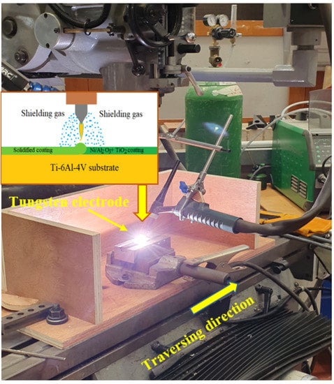
Figure 1.
Set up of the GTAW surface melting and micro-alloying process.
An Olympus Laser Scanning Confocal microscope (Olympus UK & Ireland, Southend-on-Sea, UK) was used to characterise the surface morphology (topographic profile) after the surface treatment process. Three-dimensional patterns of the surface were generated, and the roughness determined from the composite image. The laser scanning confocal microscope scans of the surface and capture successive optical sections at different heights. The software stacks the consecutive optical sections to generate a 3D image of the surface. The roughness of the surface is measured from the 3D model created. Microscopic examination of the treated surface performed using a Leitz optical microscope and a scanning electron microscopy (SEM) (FEI Quanta 400, Oxfordshire, UK) equipped with an INCA x-sight x-ray. Quantitative compositional analyses were carried out using energy dispersive spectroscopy (EDS). While the compounds formed at the surface were identified using a Bruker x-ray diffractometer (XRD) 2-theta ranging from 10° to 80° with a measuring time of 1 s per step.
3. Results and Discussion
3.1. Effect of the Coating Composition
Analysis of the treated surface showed that the composition of the coating deposited and the magnitude of the welding current or heat input strongly influence the type of microstructures that formed. Figure 2 shows the SEM micrograph of the uncoated Ti-6Al-4V surface melted with Gas Tungsten Arc Welding (GTAW) at 50 A and quenched in air. The treated layer consisted of an acicular type microstructure containing four distinct regions. Each region distinguished by variation in the composition. The upper surface includes two phases separated by the difference in shade. A similar microstructure formed in the centre of the treated layer; however, the grain sizes in this region were larger. The microstructure above the centre of the treated layer also appears to contain a similar tree-like structure (see Figure 2D). The microstructure below the centre of the treated layer contained larger grains due to the difference in cooling rates of the two regions (Figure 2E). EDS maps of the microstructure of the surface melted uncoated Ti-6Al-4V surface, as shown in Figure 2F–H. The dark grey region was a Ti-rich phase (see Table 3), while the light grey area contained to be a fine-grained tree-like structure with a high Al concentration (see Figure 2F–H) confirmed that the dark grey coloured region is Ti-rich. The light-coloured area formed due to the segregation of the Al during the solidification process.
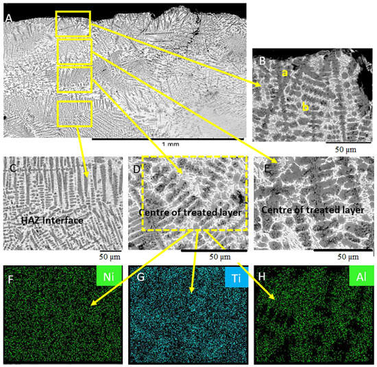
Figure 2.
SEM micrographs of the uncoated Ti-6Al-4V surface melted with Gas Tungsten Arc Welding at 50 A. (A) Width of the treated surface layer. (B) Detail microstructure of the top layer. (C) Detail microstructure within the heat-affected zone (HAZ). (D) Detail microstructure of below the centre of the treated layer. (E) Detail microstructure above the centre of the treated layer EDS maps. (F) Nickel, (G) Titanium, (H) Aluminium.
Table 3.
Chemical composition of the various phases formed during the GTAW surface melting and alloying process.
Figure 3 shows the variation in the microstructure of the Ti-6Al-4V sample, coated with Ni/Al2O3 and surface melted with a welding current of 50 A. The melted region appeared to consist of several distinct features. The upper section of the treated layer comprised of; a lamellar α+β microstructure with elongated grains originating from the grain boundaries and projecting vertically upwards towards the surface of the sample (see Figure 3B). The centre of the treated region is defined by thick light grey grain boundaries, which are shown by EDS analysis to consist of Ni, Al, and O due to the segregation of Ni and Al2O3 particles to the grain boundary regions during the surface melting process (see Figure 3D). The HAZ showed in Figure 3C appears to contain a β-Ti structure with fine grains similar to the pattern observed at the surface. The presence of the Al2O3 nanoparticles within the Ti-6Al-4V treated layer facilitates heterogeneous nucleation within the melted region during the solidification process.
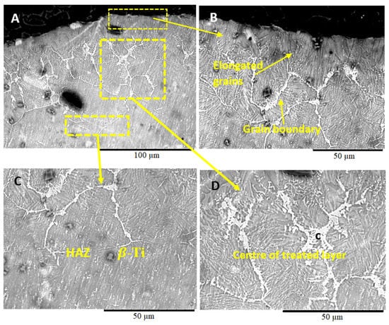
Figure 3.
SEM micrographs of Ti-6Al-4V sample coated with Ni/Al2O3 and surface melted welding current of 50 A. (B) Microstructure of the upper section of the treated layer, (C) microstructure at the middle of the treated layer and (D) microstructure at the HAZ.
Figure 4 shows the SEM micrograph of the Ti-6Al-4V surface layer coated with Ni/Al2O3 coating containing 30 nm TiO2 particles and melted with a welding current of 50 A. The 0.8 mm thick treated layer (see Figure 4A) consists of three regions. The microstructure of the upper layer of the treated zone (see Figure 4B) contained dark grey spherical particles surrounded by two reaction layers rich in Ni and Ti, as shown by EDS analysis. The second region of interest is the centre of the treated layer ((see Figure 4D), which contains a brightly coloured area labelled as “d,” containing Ni, which formed during the melting process. The heat-affected zone (HAZ) appears to contain β-Ti phases (see Figure 4C) with a small quantity of Ni distributed in this region, as shown by EDS analysis.
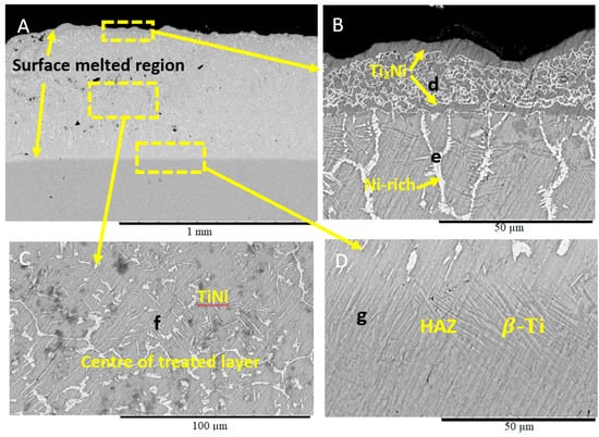
Figure 4.
Ti-6Al-4V coated with Ni/Al2O3 + 30 nm diameter TiO2 particles and melted with Gas Tungsten Arc Welding (GTAW) at 50 A. (A) SEM micrograph of the treated surface layer. (B) Microstructure at the upper section of the treated layer. (C) The microstructure of the middle of the treated layer. (D) Microstructure within the HAZ.
Figure 5 shows the microstructure of the Ti6Al-4V surface coated with Ni/Al2O3 containing 250 nm diameter TiO2 particle and surface melted with a welding current of 50 A. Melting of the surface resulted in the mixing of the nanoparticles into the surface of the Ti-6Al-4V alloy and the distribution of Ni throughout the 300 µm thick the treated layer (see Figure 5A). The heat-affected zone (HAZ) also appear to contain a stabilised β phase, due to the volume of nickel present in this region and the shape of the grains. The nanoparticles appear to have mixed into the treated layer with particle clusters formed along the top surface (see Figure 5D).
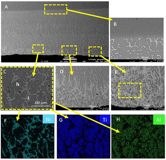
Figure 5.
(A) Ti-6Al-4V sample electrodeposited with Ni/Al2O3 + 250 nm diameter TiO2 particles and surface melted with a welding current of 50 A. (B) HAZ and (C) grain boundary region. (D) Particle segregation to the top layer. (E) Detailed view of the phase formed at the surface EDS maps for (F) Nickel; (G) Titanium; (H) Aluminium.
The melting and mixing of Ni into the surface lead to the formation of clearly defined grain boundaries regions, which highlight the segregation of Ni into these areas (Figure 5C). Mixing and diffusion led to the formation of various intermetallic compounds (IMC) within the treated layer as shown in (Figure 5E). The EDS maps provided confirm the distribution of Ni and Al2O3 within the treated layer. The EDS analysis (see Table 3) showed that the dark grey areas are made up of predominantly Ti (78.61 wt%) and Al (5.51 wt%) phase while the light grey region contained Ti (62.55 wt%), Al (2.3 wt%) and Ni (34.1 wt%) by the EDS maps presented in Figure 5C,D.
3.2. Effect of Welding Current
The impact of the welding current on the microstructure within the treated surface layer was also studied. Figure 6 shows an SEM micrograph of a Ti-6Al-4V sample that was coated with electrodeposited Ni/Al2O3 + 250 nm diameter TiO2 particle, melted with 75 A welding current and quenched in air. The microstructure of the treated surface layer appeared to contain two phases, which is defined by a lamellar structure close to the surface of the treated layer. EDS mapping of the surface melted layer shows that the dark grey phases appear to be Ti-rich regions (see Table 3), while the fine grain light grey regions appear to contain 6.82 wt% Al and 3.01 wt% Ni. The Presence of Al and O is likely from the Al2O3 and TiO2 particles that were included in the surface coating before the GTAW surface melting and alloying.
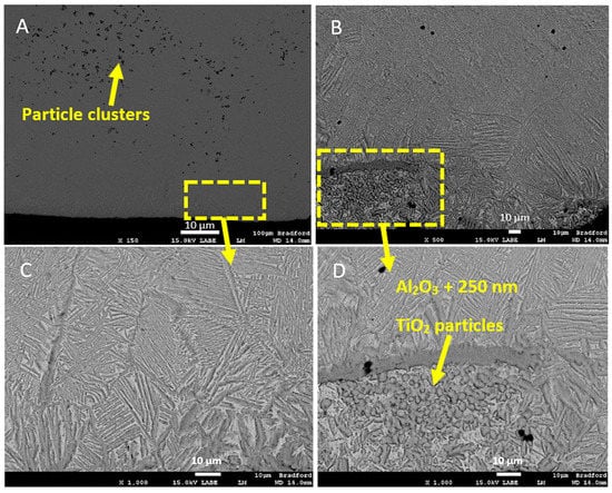
Figure 6.
SEM micrographs of Ti-6Al-4V sample electrodeposited with Ni/Al2O3 + 250 nm diameter TiO2 particles and surface melted with a welding current of 75 A and quenched in air. (A) Low-resolution image of the treated layer. (B) Particle segregation during the solidification process. (C) Detailed view of highlighted region-1. (D) Detailed view of highlighted region-2.
The microstructure of the Ti-6Al-4V sample that was coated with Ni/Al2O3 and surface melted with 100A welding current (see Figure 7) developed a lamellar structure containing two distinct phases. The two phases included a light grey region labelled-l and a dark grey region labelled “n”. EDS map of coating cross-section (see Figure 7E–G) showed that this phase contained 23.49 wt% O. While the dark grey area marked “m” appeared to be a β-Ti phase into which Ni had diffused during the surface melting and alloying process. The higher welding current used is expected to input a greater quantity of heat into the Ti-6Al-4V alloy resulting in more liquid formed at the surface of the samples during the melting process.
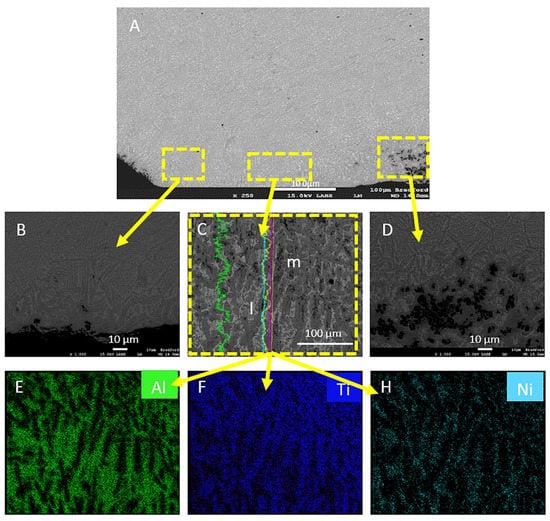
Figure 7.
(A) Ti-6Al-4V sample electrodeposited with Ni/Al2O3 + 250 nm diameter TiO2 particles and surface melted with a welding current of 100 A. (B) Low-resolution image of the treated layer. (C) Detailed view of the microstructure along the surface. (D) Micrograph showing particle segregation. EDS maps of (E) Nickel, (F) Titanium, (G) Aluminium.
The parameters of the surface melting process were varied, and the impact on the hardness, surface texture, and the composition of the surface studied. When the welding current varied between 50 A and 100 A, the results show that while the surface hardness of the samples was similar, the hardness below the surface decreased with increasing welding current as a function of depth measured from the treated surface towards the untreated base metal. Several factors are responsible for the increased hardness of surface melted with 50 A; firstly, the entrapment of un-melted remains of the coating within the surface resulted in micro-alloying and substitutional strengthening of the upper layer of the treated surface. Additionally, the nanoparticles appear to remain closer to the surface of the treated layer due to incomplete melting of the coating. The confocal analyses confirmed the presence of un-melted remains of the coating trapped in the Ti-6Al-4V surface. The micro-alloying of Ni, Al, and O into the surface of the Ti-6Al-4V alloy stabilizes the α-phase, further leading to the formation of a martensitic structure [7].
3.3. XRD Analysis
XRD analysis of the surface-treated Ti-samples determined the impact of coating type and welding current on the phases that form at the Ti-6Al-4V surface. Figure 8 shows the XRD spectra of Ti-6Al-4V samples coated with Ni/Al2O3 containing 250 nm diameter TiO2 particles as a function of welding current. The XRD spectra show four compounds; Ti2Ni, TiO2, TiNi, and Ni/Al2O3 formed at the surface, driven by the melting and mixing of the electrodeposited coating and the Ti-6Al-4V when the coating composition was varied. Similar compounds formed at the surface of samples, as shown in Figure 9. However, the intensity of the peaks for TiO2 and Ni/Al2O3 spinals appeared to have increased. Additionally, the peak for the Ti2Ni compound, which occurred at 35o, appears to decrease with the increasing welding current.
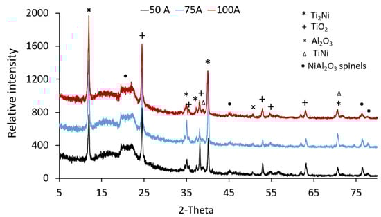
Figure 8.
XRD analysis of Ti-6Al-4V samples coated with Ni/Al2O3-250 nm TiO2 coating and surface melted as a function of welding current.
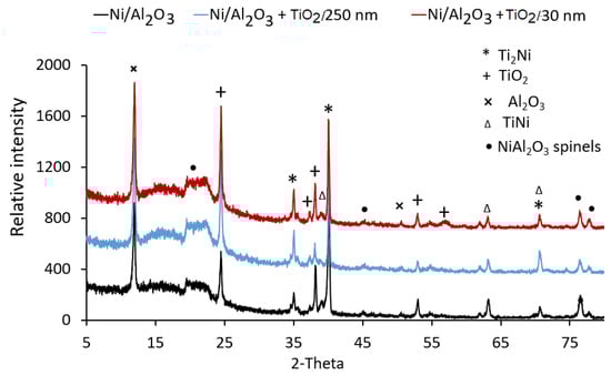
Figure 9.
XRD analysis of Ti-6Al-4V samples electroplated with three different coatings and surface melted with GTAW.
The XRD analyses of the Ti-6Al-4V treated layer showed the presence of three compounds at the surface: TiNi, Ti2Ni, and Ni/Al2O3. Evaluation of the Gibbs free energy of reaction formation indicates that the order of formation of the compounds is likely; Ti2Ni (72,985.9 J/Mol), followed by TiNi (61,595.3 J/Mol) [19]. The possible exothermic reaction during the surface melting and alloying is showing the following equation [20] with the sequence of formation following the same order.
Ti+Ni →TiNi+67 kJ/Mol
2Ti+Ni →TiNi+83 kJ/Mol
3Ti+Ni →TiNi+140 kJ/Mol
3.4. Hardness
Hardness tests evaluated the variation in the micro-hardness across the treated surfaces. Figure 10 shows the surface hardness of the Ti-6Al-4V samples as a function of coating type and welding current. When the influence of the coating type on the surface hardness was studied, the results show that the average hardness at 100 µm below the treated surface was similar for all three types of coating investigated. However, as the depth increase towards the untreated regions of the Ti-basemetal, the average hardness appeared to decrease with increasing TiO2 particle size. The sample coated with Ni/Al2O3 had the best overall performance with hardness varying between 701 HV0.2kg and 590 HV0.2kg followed by the Ni/Al2O3 coating containing 30 nm TiO2 particles with hardness varying between 701 HV0.2kg and 351 HV0.2kg for a similar depth of 1 mm.
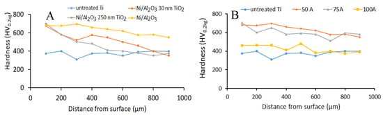
Figure 10.
Hardness profile of the surface hardened Ti-6Al-4V alloy (A) as a function of coating composition using 75 A welding current. (B) As a function of welding current using Ni/Al2O3 co-deposited coating.
When the samples were compared based on welding current, the results show that the average hardness across the range of welding currents decreased as the welding current increased. Samples that were surface melted with 50 A, welding current, had the best performance across the distance tested (see Figure 10B).
Evaluation of the relationship between changes to the composition of the coating deposited unto the Ti-6Al-4V surface and the properties of the treated surface layer showed that the average surface hardness of the treated layer decreased with increasing TiO2 particle size. The Ni/Al2O3 coating provides the best surface hardness of the treated layer, which may have resulted in grain refining, solid solution, and dispersion strengthening [21].
3.5. Surface Morphology
Figure 11 shows the impact of the coating composition on the surface morphology of the Ti-6Al-4V sample and surface melted with a 50 A welding current. The surface texture appears to follow a random configuration; however, the results show that the surface contained un-melted remains of the coating deposited on the surface at the beginning of the process. The volume of coating remaining after the surface treatment may be attributed to the low energy input into the surface during the surface melting process using a welding current of 50 A. Additionally, the roughness of the surface appears to decrease with increasing TiO2 particle size from 41.65 µm when the Ni/Al2O3 coating was applied to 7.49 µm when the Ni/Al2O3 +250 nm TiO2 particles (see Figure 12).
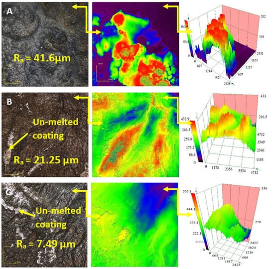
Figure 11.
Confocal micrographs of the morphology of the treated Ti-6Al-4V surfaces coated with Ni/Al2O3 containing 30 nm diameter TiO2 particles as a function of (A) Ni/Al2O3 particles, (B) Ni/Al2O3 + 30 nm TiO2particles and (C) Ni/Al2O3 + 250 nm TiO2 particles.
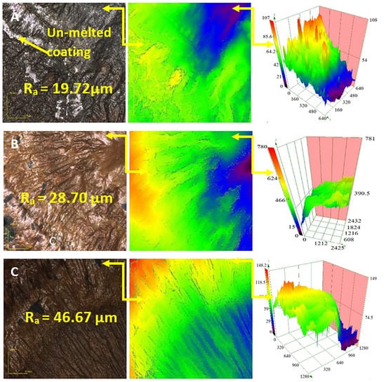
Figure 12.
Confocal micrographs of the morphology of the treated Ti-6Al-4V coated with Ni/Al2O3, including 250 nm diameter TiO2 particles and melted as a function of welding current: (A) 50 A, (B) 75 A and (C) 100 A.
The surface map presented in Figure 12 shows the high spots on the treated layer, while the 3D images show the variation of the heights of the asperities present on the surface of the treated samples.
Figure 12 shows confocal micrographs of the surfaces of the Ti-6Al-4V alloyed coated with Ni/Al2O3 containing 250 nm TiO2 particles and tested as a function of the GTAW current. The results show that the surface produced with 50 A contained un-melted remains of the electrodeposited coatings.
When the welding current was increased to 75 A and above (see Figure 12B), the entire coating was melted and mixed into the treated layer. Finally, the surface melted with 100 A (see Figure 12C) had a consistent pattern of diagonal grooves covering the surface of the sample. The confocal surface maps confirms the variation in surface topology with a change in distance measured from the centre of the samples. The result shows that the surface roughness of the samples increased with increasing welding current from 19.72 µm for sample melted with a GTAW current of 50 A to 46.67 µm for welding current of 100 A.
Analysis of the surface morphology also showed that the surface roughness increased with the increasing welding current. The changes observed at the Ti-6Al-4V surface with higher current settings were attributed to greater heat input into the surface at higher current. The higher heat input resulted in significant melting and roughening of the Ti-6Al-4V surfaces. Higher heat input may cause lower viscosity of the melt, which would allow heavier particles to settle to the bottom of the weld pool [22,23] or segregated to form isolated particle clusters due to the flow of the molten surface layer.
4. Conclusions
This study evaluated the potential of micro-alloying and surface hardening Ti-6Al-4V alloy using a novel two-step process. The Ti-6Al-4V alloy was electrodeposited with a nanostructure coating and surface melted using GTAW. The melting and subsequent solidification of the Ti-6Al-4V surface embeds the nanoparticles into the Ti-6Al-4V surface.
- The results of the study showed that the hardness of the treated layer of the Ti-6Al-4V surface could be successfully improved by embedding ceramic nanoparticles into the surface layer.
- The treated layer with the maximum hardness corresponded to the sample surface melted with 50 A welding current.
- The Ni/Al2O3 coating was more effective at doubling the surface hardness. The hardness of the surface layer decreased with the increasing size of the nanoparticles.
- The morphology of the surface is significantly affected by the welding current and coating composition. Surface roughness increased with welding current and decreased with increasing particle size.
- The heat input into the surface during the surface melting process resulted in the formation of various intermetallic compounds capable of increasing the hardness of the Ti-6Al-4V surface layer.
Author Contributions
Conceptualization, K.O.C.; formal analysis, K.O.C., and M.A.S.; investigation, K.O.C., and S.H.; methodology, K.O.C., and S.H.; writing—original draft, K.O.C.; writing—review and editing K.O.C. All authors have read and agreed to the published version of the manuscript.
Funding
This research received no external funding.
Conflicts of Interest
The authors declare that there is no conflict of interest regarding the publication of this paper.
References
- Peters, M.; Hemptenmacher, J.; Kumpfert, J.; Leyens, C. Structure and Properties of Titanium and Titanium Alloys. Titan. Titan. Alloy. 2005, 1–36. [Google Scholar] [CrossRef]
- de Viteri, V.S.; Fuentes, E. Titanium and Titanium Alloys as Biomaterials. Tribol. Fundam. Adv. 2013. [Google Scholar] [CrossRef]
- Warlimont, H. Titanium, and Titanium Alloys. In Springer Handbook of Nanotechnology; Springer: Berlin/Heidelberg, Germany, 2018. [Google Scholar] [CrossRef]
- Li, Y.; Yang, C.; Zhao, H.; Qu, S.; Li, X.; Li, Y. New developments of Ti-based alloys for biomedical applications. Materials 2014, 7, 1709–1800. [Google Scholar] [CrossRef] [PubMed]
- German, V.; Alin Pop, M.; Luca Motoc, D.; Radomir, I. Tribological Properties of Thermal Spray Coatings. Eur. Sci. J. 2013, 3, 154–159. [Google Scholar]
- Dong, H. Tribological properties of titanium-based alloys. In Surface Engineering of Light Alloys; Woodhead Publishing: Cambridge, UK, 2010; pp. 58–80. [Google Scholar] [CrossRef]
- Lütjering, G. Influence of processing on microstructure and mechanical properties of (α + β) titanium alloys. Mater. Sci. Eng. A 1998, 243, 32–45. [Google Scholar] [CrossRef]
- Saleh, A.F.; Abboud, J.H.; Benyounis, K.Y. Surface carburizing of Ti-6Al-4V alloy by laser melting. Opt. Lasers Eng. 2010, 48, 257–267. [Google Scholar] [CrossRef]
- Rizzi, M.; Gatti, G.; Migliario, M.; Marchese, L.; Rocchetti, V.; Renò, F. Effect of zirconium nitride physical vapor deposition coating on preosteoblast cell adhesion and proliferation onto titanium screws. J. Prosthet. Dent. 2014, 112, 1103–1110. [Google Scholar] [CrossRef] [PubMed]
- Lin, N.; Zhou, P.; Wang, Y.; Zou, J.; Ma, Y.; Wang, Z.; Tian, W.; Yao, X.; Tang, B. Thermal oxidation of Ti6Al4V alloy with enhanced wear and corrosion resistance for oil and gas application: Effect of temperature. Surf. Rev. Lett. 2015, 22, 1550033. [Google Scholar] [CrossRef]
- Sidhu, B.S.; Singh, H.; Puri, D.; Prakash, S. Wear, and oxidation behaviour of shrouded plasma sprayed fly ash coatings. Tribol. Int. 2007, 40, 800–808. [Google Scholar] [CrossRef]
- Lin, N.; Liu, Q.; Zou, J.; Li, D.; Yuan, S.; Wang, Z.; Tang, B. Surface damage mitigation of Ti6Al4V alloy via thermal oxidation for oil and gas exploitation application: Characterization of the microstructure and evaluation of the surface performance. RSC Adv. 2017, 7, 13517–13535. [Google Scholar] [CrossRef]
- Liu, L.; Ernst, F.; Michal, G.M.; Heuer, A.H. Surface hardening of Ti alloys by gas-phase nitridation: Kinetic control of the nitrogen surface activity. Metall. Mater. Trans. A Phys. Metall. Mater. Sci. 2005, 36, 2429–2434. [Google Scholar] [CrossRef]
- Yazdi, R.; Kashani-Bozorg, S.F. Microstructure and wear of in-situ Ti/(TiN + TiB) hybrid composite layers produced using liquid-phase process. Mater. Chem. Phys. 2015, 152, 147–157. [Google Scholar] [CrossRef]
- Cooke, K.O.; Khan, T.I.; Oliver, G.D. Transient liquid phase diffusion bonding Al-6061 using nano-dispersed Ni coatings. Mater. Des. 2012, 33, 469–475. [Google Scholar] [CrossRef]
- Cooke, K.O. Parametric Analysis of Electrodeposited Nanocomposite Coatings for Abrasive Wear Resistance. In Electrodeposition of Composite Materials; Intech Open: London, UK, 2014; p. 64. [Google Scholar] [CrossRef]
- Akhtar, T.S.; Cooke, K.O.; Khan, T.I.; Shar, M.A. Nanoparticle enhanced eutectic reaction during diffusion brazing of aluminum to magnesium. Nanomaterials 2019, 9, 370. [Google Scholar] [CrossRef]
- Easterling, K. Introduction to the Physical Metallurgy of Welding; Butterworth-Heinemann: Oxford, UK, 1992. [Google Scholar] [CrossRef]
- Shao, X.; Guo, X.; Han, Y.; Lin, Z.; Qin, J.; Lu, W.; Zhang, D. Preparation of TiNi films by diffusion technology and the study of the formation sequence of the intermetallics in Ti-Ni systems. J. Mater. Res. 2014, 29, 2707–2716. [Google Scholar] [CrossRef]
- Yang, Y.Q.; Zhang, C.H. Synthesis of TiNi-TiN gradient coating by a hybrid method of laser cladding and laser nitriding. Zhongguo Youse Jinshu Xuebao/Chin. J. Nonferrous Met. 2006, 16, 213–218. [Google Scholar]
- Gong, J.; Wilkinson, A.J. A microcantilever investigation of size effect, solid-solution strengthening and second-phase strengthening for <a> prism slip in alpha-Ti. Acta Mater. 2011, 59, 5970–5981. [Google Scholar] [CrossRef]
- Cooke, K.O.; Khan, T.I. Resistance spot welding aluminum to magnesium using nanoparticle reinforced eutectic forming interlayers. Sci. Technol. Weld. Join. 2017, 23, 271–278. [Google Scholar] [CrossRef]
- Cooke, K.O.; Khan, T.I. Microstructure Development during Low-Current Resistance Spot Welding of Aluminum to Magnesium. J. Manuf. Mater. Process. 2019, 3, 46. [Google Scholar] [CrossRef]
© 2020 by the authors. Licensee MDPI, Basel, Switzerland. This article is an open access article distributed under the terms and conditions of the Creative Commons Attribution (CC BY) license (http://creativecommons.org/licenses/by/4.0/).