1. Introduction and State of the Art
Highly stressed components, such as powertrain components, are usually heat-treated in order to adjust the strength of the microstructure for the corresponding load [
1]. Case-hardened steels are widely used, especially in drive technology. After heat treatment, workpieces are usually processed by grinding at the end of the process chain to produce high dimensional and shape accuracy and high-quality surfaces [
2,
3,
4,
5]. In addition to geometric parameters, thermomechanical loads during grinding also determine the surface and subsurface properties and, thus, the functional properties of the finished workpiece [
6,
7]. For selected testing of the surface and subsurface properties after grinding, destructive measuring methods (e.g., X-ray residual stress measurements and metallographic inspection) are well-established and widely used [
5]. Non-destructive methods have been the subject of research for several years. The Barkhausen noise (BN) analysis, as a micromagnetic measuring method, has the potential to characterize the surface and subsurface layers non-destructively with micromagnetic parameters [
2,
4,
5].
Micromagnetic Barkhausen Noise Analysis
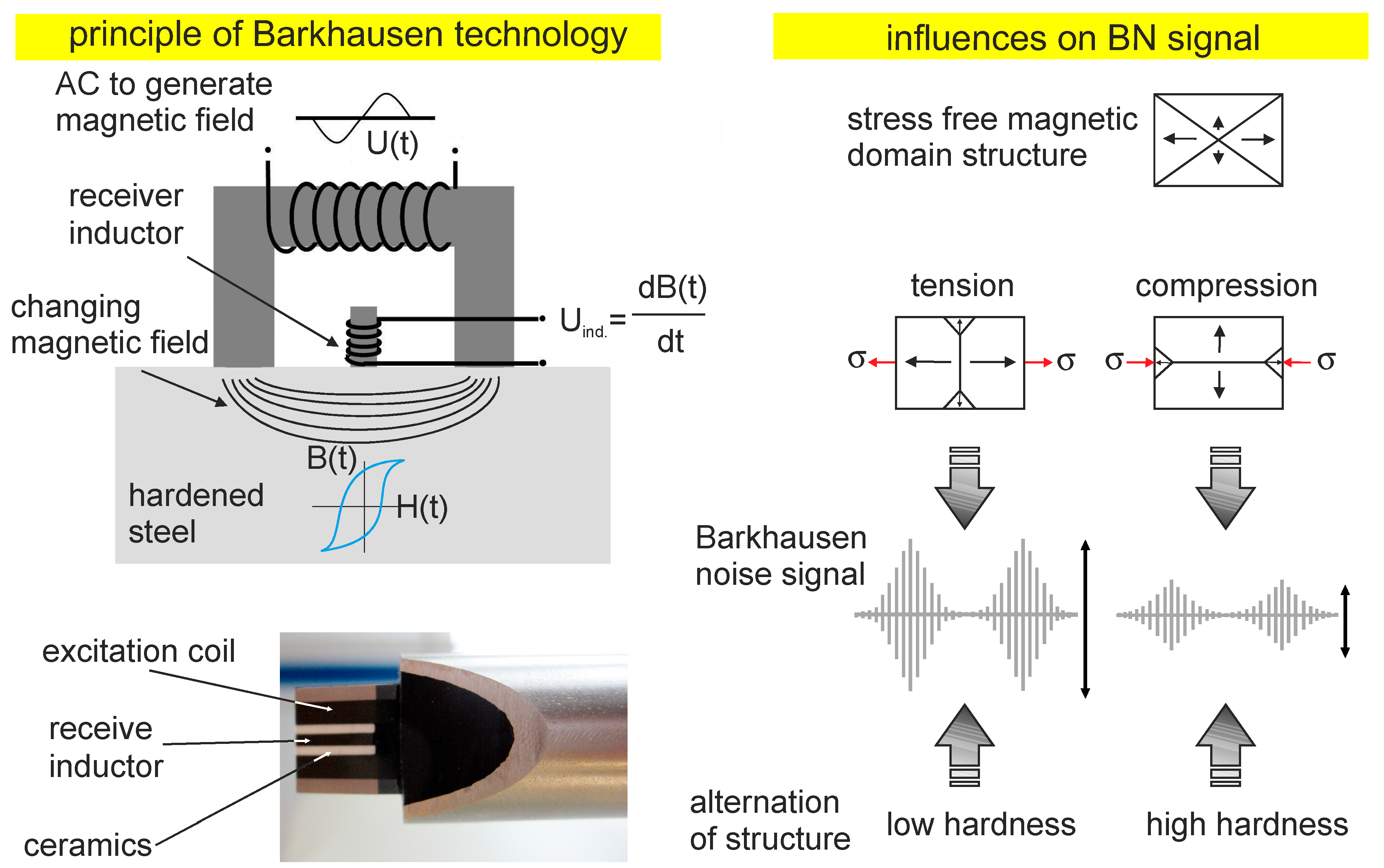
Figure 1 shows a typical measurement setup for BN measurements as a sketch. With an excitation coil (outer upper coil), an alternating magnetic field H is generated in the material, and the resulting magnetic flux density
B is detected via a receiving coil or a Hall sensor. A remagnetization of individual micromagnetic domains (called Weiss domains) are affected by discontinuous, stepwise displacements of the Bloch walls when the respective remagnetization field strength is exceeded [
8]. Since the orientation and the remagnetization energy of the Weiss domains are stochastically distributed on a macroscopic scale, the continuous field strength progression in the material is superimposed by a signal resulting from the displacement of the Bloch walls, the so-called BN [
8].
The BN is attenuated exponentially as a function of the depth reached in the material. This attenuation is mainly caused by the eddy current attenuation of electromagnetic fields [
9,
10,
11] that are generated around the moving Bloch walls. The depth
δ of the BN measurement can be estimated as follows (Equation (1)) [
10]:
Essentially, the depth δ therefore depends on the analysis frequency fa, the conductivity σ, and the permeabilities μr und μ0.
In the past, individual micromagnetic parameters (in particular the BN amplitude) for the assessment of ground workpieces, have often been tested for correlation with the residual stress state, hardness, dislocation density, and chemical homogeneity of the microstructure [
2,
5,
12,
13].
If the surface and subsurface layers of a workpiece exhibit reduced hardness or tensile residual stresses due to the thermal damage, the level of the BN signal increases [
4,
14]. More than 20 years ago the suitability of the method for grinding burn testing was shown [
4,
15]. Using 3MA test equipment from the Fraunhofer Institute for Nondestructive Testing (IzfP), Saarbrücken, Germany, quantitative investigations of hardness and residual stresses were carried out in References [
4,
16]. In Reference [
17], the grindability of case-hardened steels was investigated and the BN was used to detect damage. Two different materials (20MnCr5: No. 1.7147; AISI 4820; and 18CrNiMo7-6) and two different case hardening depths (CHDs) were used. Further research is described in Reference [
7], where two micromagnetic methods were used to perform a grinding burn test and quantitative hardness and residual stress measurements after grinding. The investigations show that a correct interpretation of the BN signal as well as other micromagnetic parameters requires calibration on the basis of good and bad parts, even for a qualitative evaluation. The surface and subsurface condition of these parts must be exactly defined with alternative test methods and assigned to the respective BN level [
18]. The reason for this is the fact that the surface and subsurface state is defined by different surface and subsurface properties (e.g., residual stress state, hardness, microstructure), so that changes in several properties simultaneously cause overlapping micromagnetic effects. Thus, the measurement result of the BN amplitude cannot be clearly assigned to the change of a certain surface and subsurface property. In order to obtain meaningful results based on the measurement of micromagnetic parameters, micromagnetic multiparameter approaches came into focus.
In 1995, for example, Karpuschewski [
4] developed a classification scheme for ground, case-hardened components with regard to possible surface and subsurface damage by combining various micromagnetic parameters of the 3MA equipment technology. This allowed for fast post-process grinding burn detection. A non-destructive, objective, quick, and economical detection of grinding errors was achieved with this device technology [
2,
19]. Both, the occurrence of tempering zones and the formation of re-hardened zones can be determined [
2]. In 1996, Suominen and Wojtas [
10] presented a comparative study of BN and X-ray diffraction measurements on ground ferritic steel samples based on the Rollscan device technology by Stresstech. In addition to the root mean square value of the BN amplitude, other micromagnetic parameters were evaluated [
10]. Thus, an increase of the parameter called “peak position” was accompanied by a higher hardness. Thiemann [
20] presented a two-parameter approach based on Stresstech device technology in 2019 which enables a clear non-destructive characterization of the machined surface, even if re-hardened zones or retained austenite transformations occur which lead to overlapping micromagnetic effects. For workpieces of case-hardened steel 18CrNiMo7-6, a large number of gradations of thermo-mechanically damaged surface and subsurface changes were produced by an external cylindrical grinding process. These gradations were generated by taper grinding over the circumference of the workpiece [
1,
20]. In these tests, the depth of cut
ae continuously increased during a total of one workpiece revolution. In addition to the root mean square value, Thiemann et al. [
1] used the peak position parameter to determine the differences. This describes the position of the maximum BN and, thus, the coercivity
HcM. Further information about the micromagnetic parameters of the Rollscan device are provided in Reference [
21].
Besides the investigation of multiparameter approaches, Karpuschewski et al. [
22,
23] also tried to detect BN in-process. Due to the lack of protective layers, the sensor showed serious signs of wear and impairment in the workpiece surface. This is where the research approach described above becomes useful. As a result of the development of sensor technology and the application of a wear protection layer on the sensors, this approach is now being revisited. In combination with the analytical approach of Malkin [
24,
25] for the thermal surface and subsurface area of influence, which is based on the process parameters of the grinding process, a distinction between good and rejected ground parts can be achieved.
2. Motivation and Research Approach
Barkhausen noise, as a non-destructive testing method, is of significant importance, especially in grinding technology when reliable and reproducible statements are needed regarding the surface and subsurface state of ground workpieces. However, due to the opposing effects caused by the different micromagnetic properties of different surface and subsurface properties, ambiguities in quantitatively determined micromagnetic characteristic values often prevent unambiguous statements. Therefore, the aim of this work was a combined evaluation of several measured micromagnetic parameters. An alternative to this evaluation method is in-process measuring of the BN level during grinding. By measuring the BN amplitude continuously during processing, the corresponding micromagnetic parameter can be unambiguously interpreted even without measuring further parameters. In the following, the stress sensitivity of the BN on case-hardened and machined 18CrNiMo7-6, in combination with the analytical model for the thermal surface and subsurface area influence of Malkin, was considered. The aim was to make a clear statement about the surface and subsurface state of the ground workpiece to distinguish between a good and a rejected part.
Analytical Model for Thermal Surface and Subsurface Area Influence According to Malkin Malkin’s [
24,
25] approach is based on the analysis of the specific grinding energy
ec; this is calculated from the quotient of the grinding power
Pc and the material removal rate
Qw, where
vc is the cutting speed and
Ft the tangential force.
The grinding energy is composed of the energy components for chip formation, plowing, and sliding [
25,
26].
If the proportion of the grinding energy is considered which flows into the workpiece surface and is converted into heat, it can be assumed that the maximum temperatures in the shear plane reach the melting temperature range of the processed material. However, these extreme temperatures only occur locally, whereas thermally induced surface and subsurface influences occur on a plane. This plane is considerably larger than the chip formation plane. Thus, these maximum temperatures can be neglected when the contact zone temperature is estimated. In order to calculate this temperature, Jaeger [
27] assumes that the contact zone moves over the workpiece surface as a heat source during grinding [
26,
27]. According to Jaeger [
27], the maximum dimensionless surface temperature is calculated as:
Taking into account the geometrical conditions of cylindrical grinding, the energy distribution and the thermal properties of steels, the critical specific grinding energy
ec* can be calculated for a given critical temperature
at which grinding burn occurs [
25,
26].
Malkin [
25] investigated various flat and cylindrical grinding processes and determined the specific grinding energy for the point where grinding burn occurs. If these energies are plotted over the product
deq0.25 ae−0.75 vw−0.5 from Equation (5), factor
B can be determined by linear regression to 7.2 J/(mm
2⋅s
0.5) (or 8.8 J/(mm
2⋅s
0.5) with graphical determination) from the diagram shown in Reference [
25]. Taking into account the thermal properties of steel, it can be determined that the critical temperature leading to the occurrence of grinding burn is approximately
θm* = 650 °C [
25,
26].
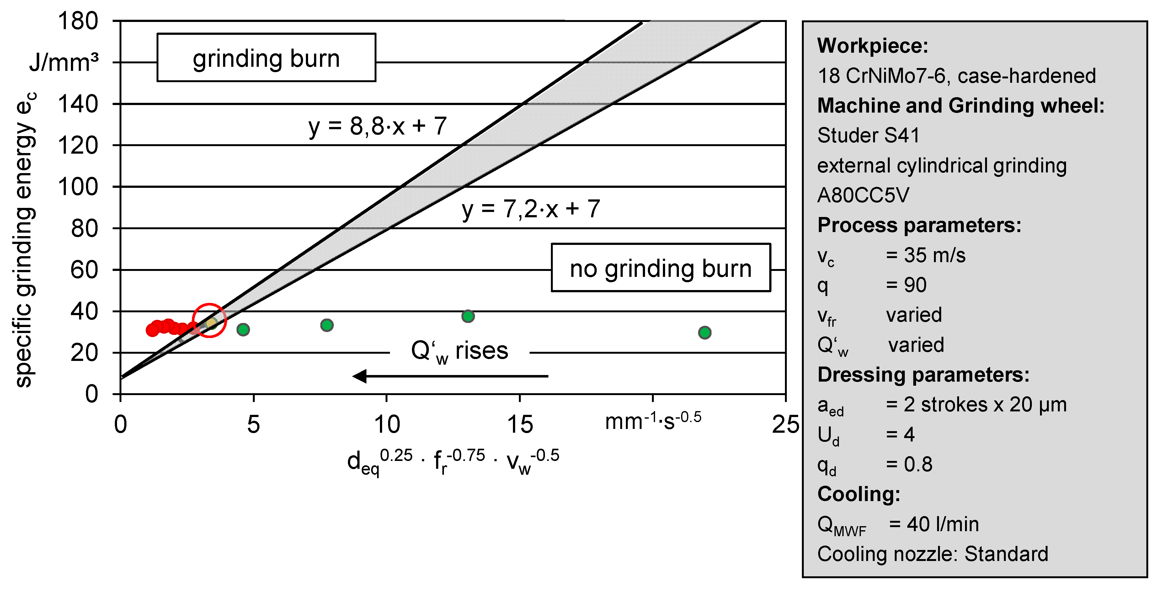
Figure 2 shows the linear grinding burn limit for the two different factors
B according to Malkin [
25]. The area between the two linear lines for the burning limits is colored grey and is regarded as a transition area in the following. In addition, grinding burn limits from taper grinding on disks made of case-hardened steel 18CrNiMo7-6 from Reference [
6] are plotted. This special external cylindrical grinding process, in which the depth of cut increases continuously during one workpiece revolution, leads to a critical temperature being reached after the grinding burn limit, as a result of the critical depth of cut being exceeded. In Reference [
6], the critical depth of cut or the location of the occurrence of grinding burn was investigated by the aid of nital etching, the evaluation of the increase of the BN amplitude, and the decrease of hardness on five workpieces with taper grinding.
It can be seen that the experimentally determined values for
ec,crit were in the same range, but with the exception of one experimental point, which were all above the grinding burn limit determined by Malkin [
25]. This makes the limits of the thermal surface and subsurface area influence appear plausible [
26]. Nevertheless, workpieces in an industrial environment are often regarded as rejects before the occurrence of visible grinding burn which could be a sign of an unintentional beginning phase transformation. This results in the following procedure for micromagnetic analysis of thermally induced influences on surface integrity using the burning limit approach of Malkin are as follows. Although Malkin’s approach makes it possible to obtain indications of the occurrence of phase transformations, no statement can be made about the residual stress state, especially before visible grinding burn appeared. This is why it is necessary to detect a condition in which, primarily, only a displacement of residual stresses in the direction of tensile residual stresses or the occurrence of slight tensile residual stresses took place. Therefore, the often-cited stress sensitivity of the BN is used in the following to investigate Malkin’s model with regard to industrial relevant limits by aid of the root mean square value of the BN amplitude. Sridharan et al. [
28] applied Malkin’s grinding energy partition model in conjunction with BN analysis to predict occurrence of thermal damage in through-hardened bearing steels independent of grinding variables. The new aspect of the following approach is the plot of the surface and subsurface property residual stress states versus the product
deq0.25 ae−0.75 vw−0.5 of Malkin’s. In this context, it was examined to what extent the measurand residual stress state was represented by the measured root mean square value of the BN in consideration of the micromagnetic analyzing depth.
In order to achieve this aim, specimens were ground under variation of process parameters and the corresponding specific grinding energy ec was plotted versus the product deq0.25 ae−0.75 vw−0.5 according to Malkin. Afterwards, the residual stress states of each experimental point were measured and represented above Malkin’s product deq0.25 ae−0.75 vw−0.5. After, the dependency of the root mean square value of the BN on the residual stress state was checked.
3. Experimental Setup
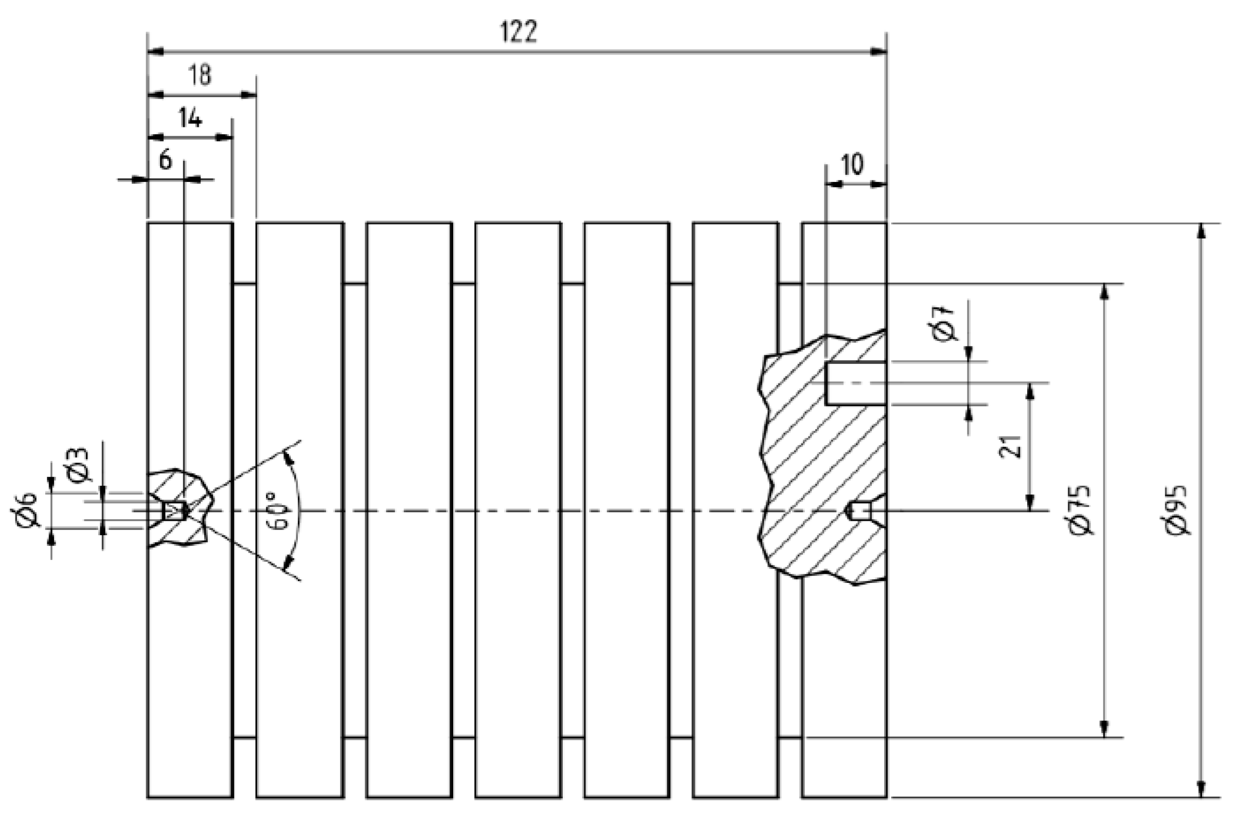
In the context of this work, cylindrical case-hardened 18CrNiMo7-6 workpieces with seven separate sections, as shown in
Figure 3, were machined by a cylindrical outer diameter grinding process with variation of relevant process parameters. The process-specific influenced material states of each section were measured by the micromagnetic BN method and compared with the results of residual stress measurements of a X-ray diffractometer (Seifert, type: 3000 PTS).
The grinding tests were carried out on a Studer S41 cylindrical grinding machine tool. The workpieces were clamped between centers. Oil as metal working fluid was used. The grinding experiments were carried out by use of a corundum grinding wheel A80CC5V (400 mm × 15 mm) in counter-direction with a constant fluid flow rate of
QMWF of 40 L/min. The grinding wheel was dressed with a Chemical Vapour Deposition (CVD) form roller with a speed ratio
qd of 0.8 and a dressing overlap
Ud of 4. During the grinding process, process forces (tangential force
Ft, normal force
Fn) were recorded by a piezoelectric measuring system integrated in the workpiece spindle and tailstock. In addition, the effective power of the grinding spindle was documented. The radial removal of the single-stage grinding process was 175 µm, which corresponded to a specific material removal volume
V′
w of approximately 50 mm
3/mm. Due to the variation of the radial feed speed
vfr, the specific material removal rate
Q′
w was set between 1 and 25 mm
3/(mm∙s) (
Table 1).
The cutting speed, vc, and the workpiece speed, vw, were kept constant with vc = 35 m/s and a resulting speed ratio q = 90. These machining parameters were selected on the basis of empirical values from conventional external cylindrical grinding.
A Rollscan 350 from Stresstech was used for the micromagnetic workpiece analysis. In order to avoid handling influences on the BN measurements with the Rollscan technology, manual usage of the sensor should be avoided. Therefore, the Klingelnberg P40 gear metrology center was used, which has an inbuilt interface between the Rollscan 350 device and the specially designed BN sensor S1-14-12-29 (
Figure 4).
By operating the travel axes, reproducible measurements can be made on slowly rotating workpieces clamped in a three-jaw chuck. The measurements were made with a magnetizing voltage of 5 V and a magnetizing frequency of 125 Hz. The analysis frequency range was 70–200 kHz. These magnetizing frequencies and analysis frequency ranges used in practice lead to an estimated analysis depth of approximately 20–50 μm, whereby a hardened martensitic microstructure of approximately 60 HRC is assumed. This estimation appears plausible according to the data of the analysis depths for soft and hard steels in Reference [
10].
4. Results and Discussion
Figure 5 shows the specific grinding energy of the external cylindrical grinding tests plotted versus the product
deq0.25 ae−0.75 vw−0.5 according to Malkin. The product
deq0.25 ae−0.75 vw−0.5 was realized by the adjustment of different radial feed speeds,
vfr, and the resulting different nominal radial feeds,
fr, which corresponded, here, to the depth of cut
ae. Since, according to Equation (2), the grinding energy
ec depends on the measured tangential force
Ft, it should be mentioned that the tangential force,
Ft, can usually be measured with a standard deviation of less than 5% from three identically machined workpiece sections.
It can be seen that four experimental points (green) lie below or to the right of the grinding burn limits determined by Malkin [
24,
25]. One single experimental point (yellow) lies exactly between the two lines. All other experimental points (red) are located on or above the grinding burn limit line with a gradient of 8.8 J/(mm
2∙s
0.5).
According to Malkin, the grinding experiments belonging to these experimental results must have produced rejected workpieces. Since it was the aim to detect an excess of the critical residual stress state of the surface and subsurface area with BN, the analysis depth of the BN was estimated at 50 µm. Subsequently, residual stress depth curves in the grinding direction were prepared in four depth steps down to a depth of 50 µm. Each measurement was measured with a standard deviation of less than 20 MPa. Afterwards, a residual stress state per surface and subsurface was determined by averaging over each depth profile. In order to calculate an averaged residual stress state, the integral of the depth profile from 0 µm to 50 µm was calculated and divided by 50 µm.
Figure 6 shows the residual stress state (0–50 µm) above the product
deq0.25 ae−0.75 vw−0.5. Of note is the experimental point from
Figure 5 (see above), which lies between the two grinding limit lines of Malkin and was calculated with an average residual stress state of almost 0 MPa (
Figure 5 and
Figure 6, red circle). While all experimental points lying on, above or left of the line of Malkin (red test points) have a tensile residual stress state, the residual stress state of all points lies below or right of the lines of Malkin (green experimental points) in the compression range. In addition,
Figure 6 shows microsections of ground workpiece sections, which were machined with specific material removal rates
Q′
w of 12 mm
3/(mm⋅s) and 22 mm
3/(mm⋅s). The microsections showed a visible annealing zone from approximately 10 µm (
Q′
w = 12 mm
3/(mm⋅s)) to more than 50 µm (
Q′
w = 22 mm
3/(mm⋅s)). The micrographs confirm the assignment of these experimental points to the grinding burn area.
In order to be able to determine the measurand residual stress state using the root mean square value of the BN amplitudes, named the
mp-value, the correlation of the
mp-value to the measured variable must be evaluated.
Figure 7 shows the
mp-value as a function of the residual stress state. The depicted
mp-values were calculated as the averages of 1000
mp-values measured over the circumference of the workpiece. The error bars correspond to the standard deviation.
It can be seen that there was an approximately, proportional, and quadratic relationship among the residual stress displacement of the residual stress states from the compression range in the direction of the tension and even up to the tension range. This proportionality was disturbed at higher residual stresses. At higher thermomechanical loads, an increasing development of annealing zones and (
Figure 6, microsections) a decrease in hardness was observed in Reference [
29]. Thus, different material reactions must have a counteracting effect on the micromagnetic properties.
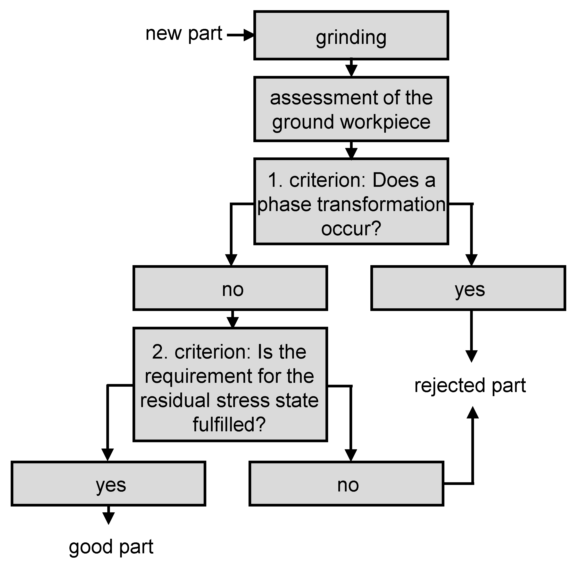
Due to the fact that tensile stresses possibly impair the functionality of ground parts by favoring the propagation of cracks, workpieces with tensile residual stresses in the surface and subsurface area are often regarded as rejected parts. An in-process monitoring and analysis of the power consumption using the process model developed by Malkin combined with a monitoring of the
mp-values bear the capability for providing a reliable statement about the condition of the surface integrity of a ground workpiece. The procedure to deal with these criteria to differentiate between good and rejected parts is shown in
Figure 8.
The question of the first criterion can be answered with “no” if the grinding burning limit of Malkin, which indicates the possibility of a beginning phase transformation, is not reached. The second criterion results in a good part when the requirement for the residual stress state in terms of the compliance of certain
mp-values is fulfilled. This condition has to be previously defined by a calibration procedure. If the requirements for the residual stress state is 0 MPa, the threshold
mp-value must be set to 44, as shown in
Figure 7 (yellow experimental point). This assessment of ground workpieces is applicable in fast post-process mode and is suitable in an industrial multi-stage grinding process. After each process step, the current workpiece residual stress state can be checked, considering the process parameters and Malkin’s burning limit. This helps to achieve a process, which is as productive as possible, for example, the first stage of the grinding process was carried out in such a way that a part was indicated as rejected. Due to this fast post-process control, the following grinding steps can be adapted, so that the negative influenced surface and subsurface layers are removed in order to finally generate a good part.
Future research will focus on a setup for in-process measurements of BN. In the context of cylindrical outer diameter grinding experiments, the radial feed speed vfr will be used for a controlled process based on in-process monitoring of BN considering the burning limit of Malkin.


