1. Introduction
Dimensional accuracy and the surface integrity of manufactured products are key specifications that determine conformance to the design intent. The adherence to these specifications is an indication of the quality of the product and that it will meet the needs of customers. Temperature variation during manufacturing can influence both the dimensional accuracy and the surface integrity of the product. Therefore, temperature control or compensation of the thermal effects is essential in order to produce high quality components.
Exact temperature variation values are not given in the literature, as it is difficult to get a generic value due to different manufacturing processes. However, temperature variation in a workpiece during machining can reach 10 °C. A 10 °C variation will result in a differing expansion in different materials. In precision manufacturing, workpieces often need to be machined with a dimensional error of less than 5 µm. The accuracy and resolution with which workpiece temperature needs to be measured for different materials is given in
Table 1.
The core temperature variation of metals affects their dimensional accuracy. The existing temperature measurement methods in manufacturing are limited in that they only represent the surface temperature of the workpiece. This paper investigates the possibility of creating a novel system for the precision core temperature measurement of metals which can be adapted for use in different manufacturing processes. One such manufacturing process is the machining process. Metal cutting is arguably the most important aspect of manufacturing and there have been advancements in optimizing the rate of metal cutting. New technologies have helped to increase the cutting speed, depth of cut and feed rate. However, with these increments also comes the increase in heat generation originating near the tool–workpiece interface [
2]. Combined with effects from change in ambient temperature, heat sinking to fixtures and non-deterministic heat transfer between the component and cutting fluids, indirect monitoring of the temperature of the workpiece is a very challenging problem. Most of the temperature measurement techniques for manufacturing described in literature only deal with the machine [
3] or cutting tool temperature [
2].
One of the temperature measurement methods for workpieces reported in literature is the tool/workpiece thermocouple [
4,
5,
6]. The main difficulties reported concerning the use of this method are the parasitic electromotive force (EMF) from secondary joints, the necessity for the accurate calibration of the tool and workpiece as a thermocouple pair, the need to isolate the thermocouple from the environment and the lack of clarity on what the EMF represents [
5,
6]. Also, this method does not indicate the core temperature of the workpiece. Infrared thermometry is another method that has been used in both dry conditions and with the presence of coolant [
7]. However, the measurement only represents the surface temperature, and the accuracy that can be achieved with this method is less than the required accuracy for the precision machining of some materials, as infrared cameras’ stated accuracy is typically ±2 °C [
8]. Moreover, this value is only valid in ideal conditions, as the accuracy will greatly reduce in harsh machining environments. Infrared cameras also require a good line of sight to work. Of all the methods previously used, none gives a direct indication of the core temperature of the workpiece, which is the parameter that affects the dimensional expansion.
The speed of sound in any material is dependent on the temperature of the medium of propagation. This dependence has been used in a variety of ways to measure the temperatures of different media. The pulse-echo technique uses the time-of-flight method to measure ultrasonic velocity which can then be related to the temperature of the medium [
9]. The pulse-echo method is relatively simple, but the resolution of measurement may reduce with distance due to attenuation of the echo signal [
10]. Another main technique is the continuous wave method which evaluates the distance of ultrasonic travel by computing the phase-shift between transmitted and received signals [
11]. Some modifications and combinations of the two techniques have also been used, such as the two-frequency continuous wave method [
11,
12] and multiple frequency continuous wave method [
13,
14]. These techniques make use of two or more ultrasonic frequencies to increase the range of measurement and improve resolution.
Hu et al., using the temperature range of 25 to 200 °C, modified the ultrasonic velocity equation based on the effects thermal expansion has on the travel path of ultrasonic waves. They reported an increase in accuracy based on the compensations made for expansion [
15]. Another recent work by Ihara et al. is the use of laser ultrasonic thermometry to measure the internal temperature of heated cylindrical rods. The authors reported that the results almost agree with those measured using a thermocouple, however the accuracy of the method is not sufficiently described [
16]. Different methods of ultrasonic measurement have been used and modified for use in different fields of measurement, however, their use in precision manufacturing is not sufficiently described in the literature.
This paper explores the use of ultrasonic waves for the precision core temperature measurement of a steel workpiece. The results from simulation using the two main techniques are evaluated to find the best option for core temperature measurement in metals. The initial work consists of simulations in the k-Wave MATLAB toolbox—an open source toolbox for time domain acoustic and ultrasound simulations [
17]. This was used to study the two main ultrasonic thermometry methods—the ultrasonic pulse-echo and phase-shift methods. k-Wave was chosen for simulation because of its flexibility for defining different parameters and media of interest—it also gives a real-time A-scan of the propagation medium during simulation, as well as its propagation plot. In an A-scan, the amplitude of an ultrasonic pulse is represented as displacement in y-axis and the corresponding travel time is represented on the
x-axis. Based on the simulation results, ultrasonic phase-shift experiments were conducted in a metrology laboratory and the results of these experiments will serve as input to a future experiment which involves the use of the developed techniques in subtractive manufacturing processes.
2. Materials and Methods
The Pulse-echo method is the traditional means of ultrasonic measurement. It uses the principle of time-of-flight (
tof), where an ultrasonic pulse is propagated through a medium and the pulse is reflected when it encounters a medium of different physical property [
18]. The
tof from the ultrasonic transmitter to the receiver and the length of the travel path is used to compute the ultrasonic velocity [
19]. This relationship is given as:
where
c is the ultrasonic velocity,
d is the distance travelled and
tof is the time of flight [
20].
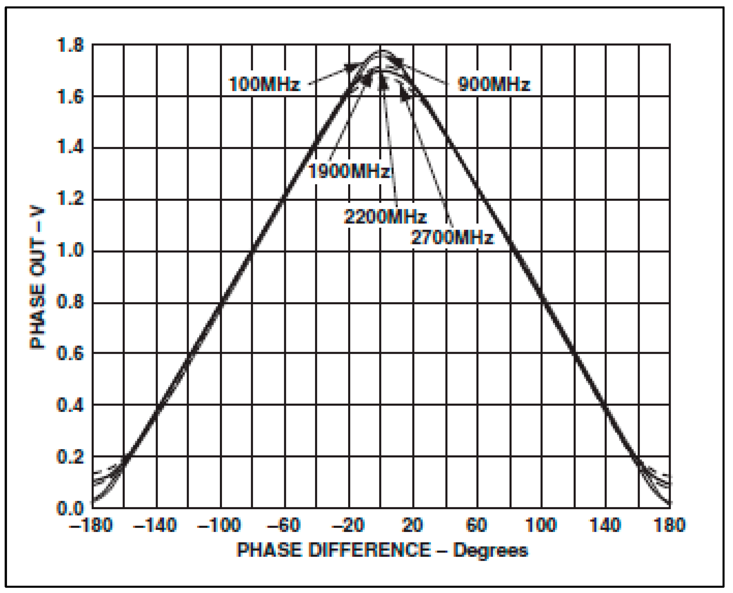
The phase-shift method, on the other hand, uses the difference in the phase of steady state frequency ultrasonic wave between transmitted and received signals [
13]. For an ultrasonic wave of known frequency travelling through a known distance, the phase difference between the transmitted and received signals can be used to compute the ultrasonic velocity through the medium. The relationship between the ultrasonic velocity and phase-shift is given in the equation below:
where
L is the distance between the transmitter and receiver,
n is the integer number of wave periods,
ϕ is the phase-shift,
f is the ultrasonic frequency and
c is the ultrasonic velocity through the medium [
19].
A modification of the phase-shift method which considerably improves both the range and resolution of measurement is the two-frequency continuous wave method (TFcw). It uses two frequencies for ultrasonic velocity computation. The TFcw equation is given as:
where
c is the ultrasonic velocity,
L is the length of travel, Δ
f is the difference between the two frequencies (
f1–f2) and Δ
ϕ is the difference between the phase-shifts given as [
13]:
By adding a third frequency, the range and the resolution can both be further improved. This technique is known as the multiple frequency continuous wave method (MFcw) and the MFcw equation is given as [
21]:
2.1. Simulations
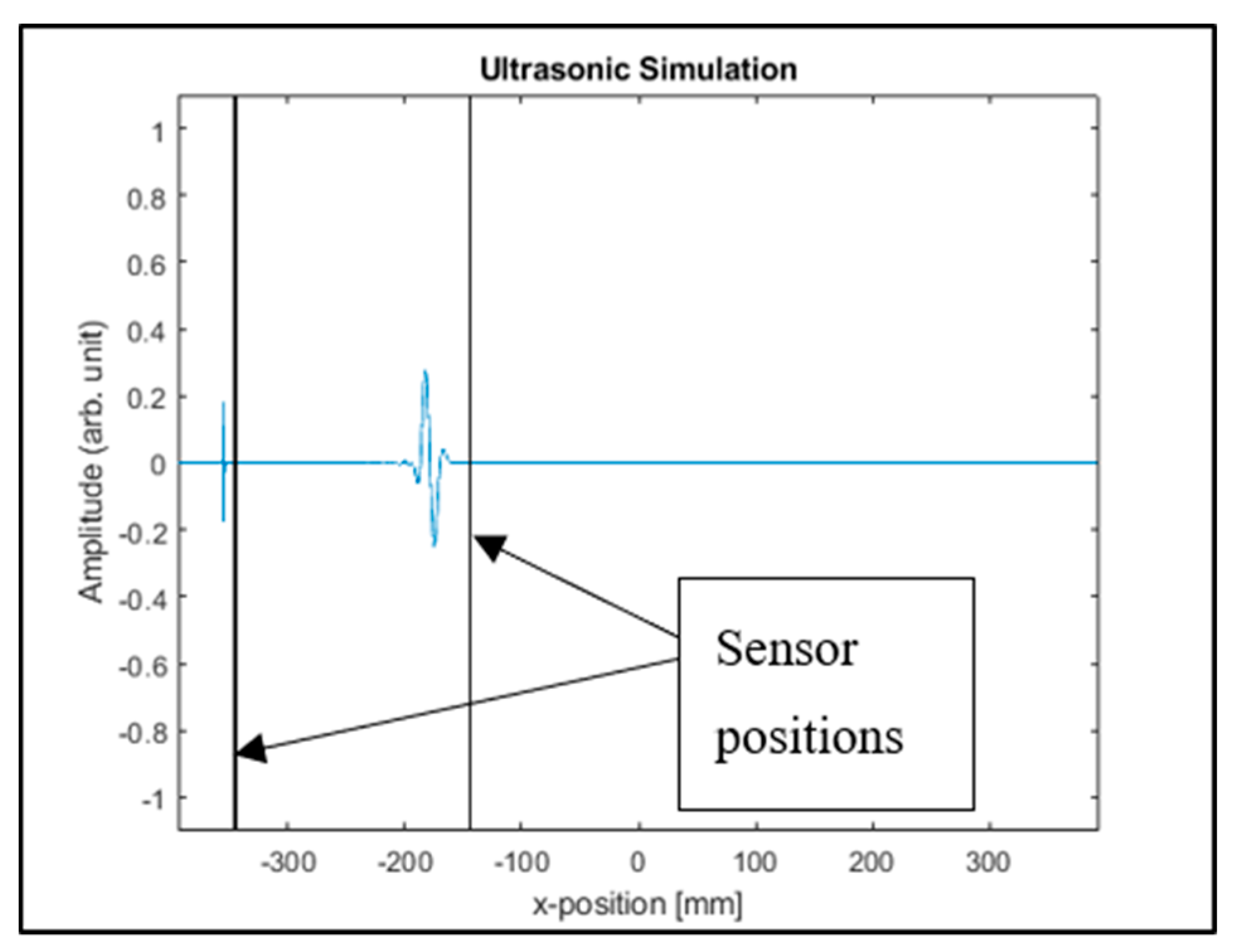
Three simulations were performed in MATLAB R2017b using the k-Wave toolbox. The first simulation was set up to resolve 0.1 °C change in temperature with
tof of ultrasonic wave. Steel was chosen as the medium of propagation with a nominal length of 200 mm. The k-Wave grid (
Nx) was defined as 6.561 × 10
3 grids, the spacing (
dx) was defined as 1.2 × 10
−4. The ultrasonic wave parameters were set up to achieve sensitivity of 0.1 °C. The sensor position for the simulation is given in
Figure 1.
The ultrasonic velocity used is based on the temperature–velocity relationship given by Ihara et al. [
22]. This is given as:
where
v(
T) is the temperature-dependent ultrasonic velocity and
T is the temperature.
The simulation was run over the range of 25 to 25.5 °C to observe if the corresponding change in time of flight can be reliably measured. Equation (6), which was used for the simulation, is almost linear for a temperature range of 0–200 °C [
22]—hence, in this simulation, the sensitivity is prioritized over range. The peak detection technique was used to record the time the ultrasonic pulse strikes the sensor at both the transmitting and receiving positions [
20].
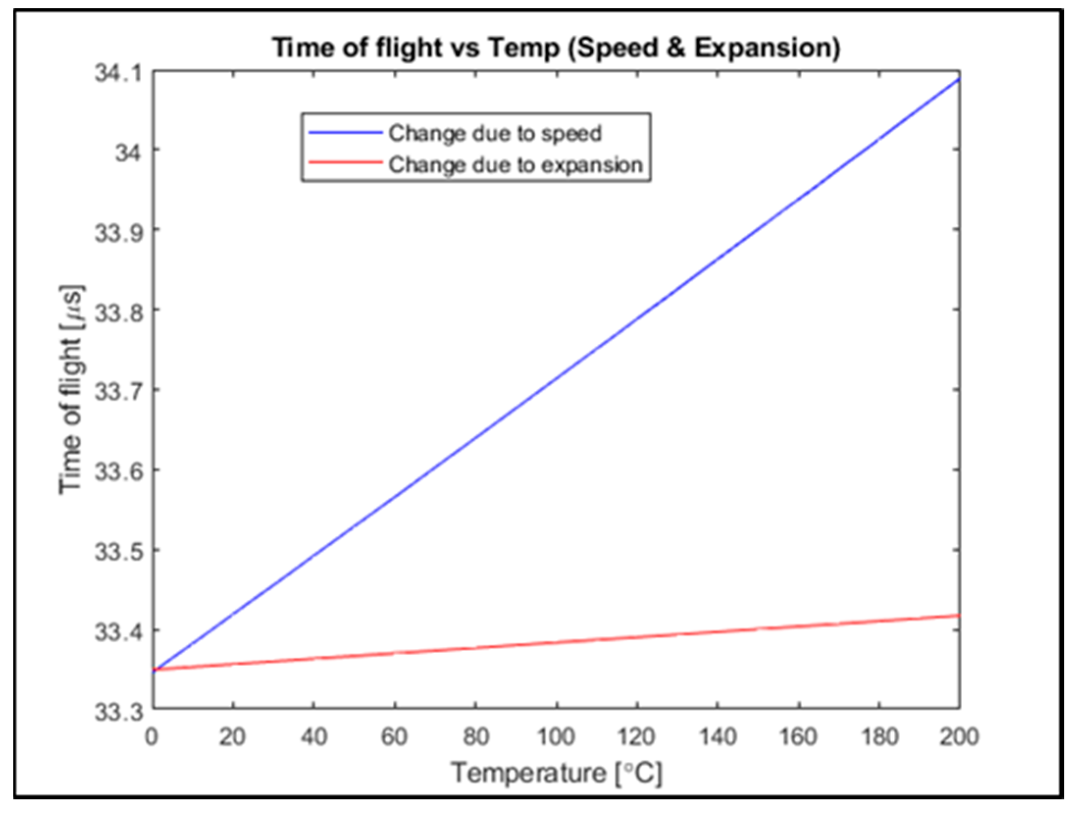
The second simulation was carried out to observe the individual effect of change in ultrasonic velocity and change in material dimension (expansion) on
tof. This was performed in order to verify if the
tof can be reliably estimated from the change in velocity alone, expansion alone or by combining both. The ultrasonic velocity was varied using Equation (6), while material expansion was varied using Equation (7) given below:
where Δ
L is the change in length,
αL is the linear coefficient of thermal expansion, Δ
T is the change in temperature and
L is the original material length.
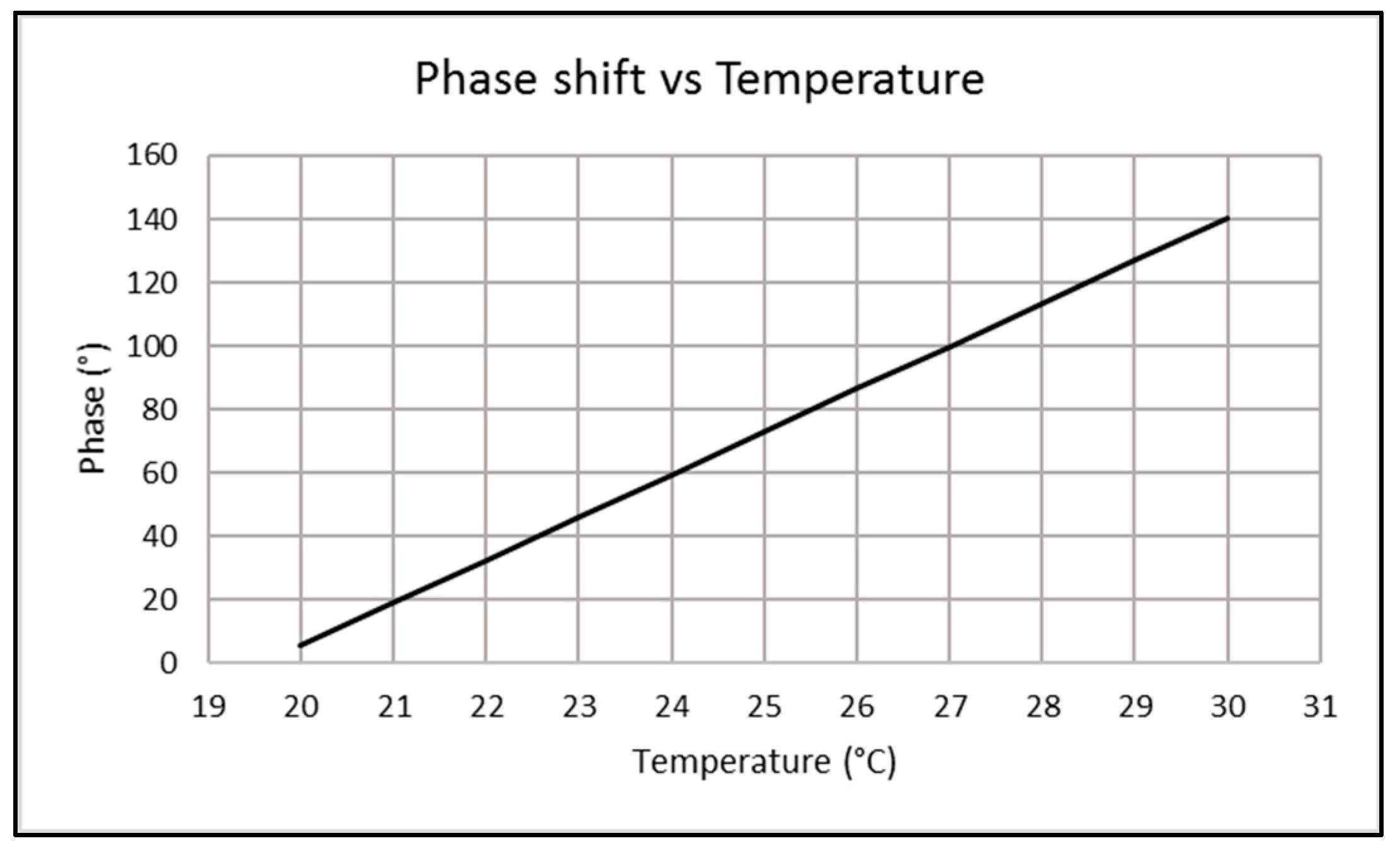
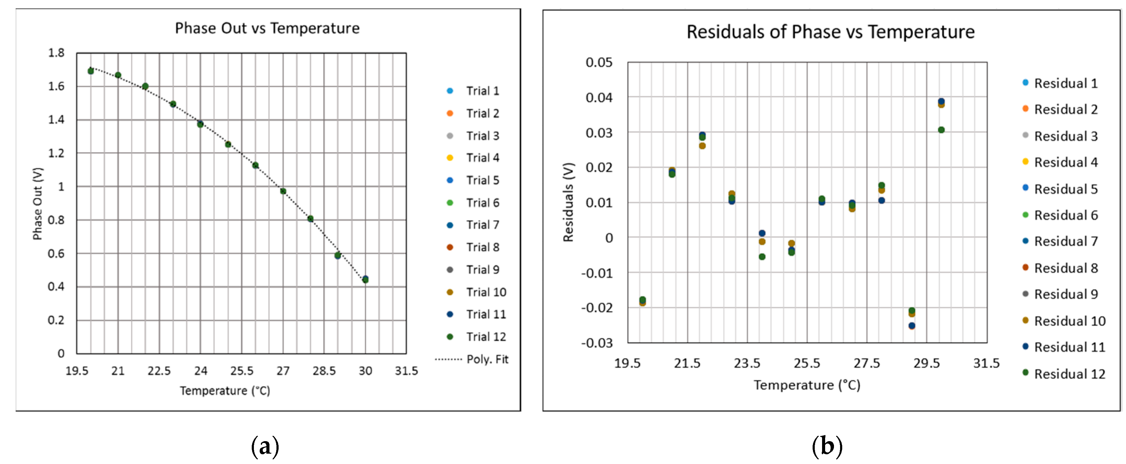
The third simulation was performed using the phase-shift method, with the aim of obtaining the frequency pair which can consistently sense a 0.1 °C change in temperature. This same simulation was modified for the MFcw method and, for this simulation, the length of material was scaled down by a factor of ten to reduce computational load. Also using the phase-shift method, a simulation was performed for a 15 mm piece of steel—this was performed to predict the possibility of using the 5 MHz transducer to obtain a 10 °C range and 0.1 °C resolution.
2.2. Simulation Results
In order to achieve a measurement resolution of 0.1 °C, a tone burst of 1.2 MHz and sampling frequency of 10 GHz were used. The recorded tone burst at 25 °C and the
tof for the whole range of simulations are given in
Figure 2 and
Table 2 respectively.
With 10 GHz sampling frequency, a 0.1 °C change in temperature will cause a change in time of flight that can be resolved at the fourth decimal place of tof in microseconds. The costs of pulsers/receivers that sample at 10 GHz frequency are considerably high.
From the findings of Ihara et al., the relationship between ultrasonic velocity and temperature is almost linear within the range of 0 to 200 °C [
22], as is the effect from the change in distance from thermal expansion. The simulations for expansion and ultrasonic speed were performed over this linear range. The result of this simulation is shown in
Figure 3.
Figure 3 shows that the time of flight varied largely due to changes in velocity, while the variation due to expansion is relatively smaller. Expansion across the range of 0 to 200 °C is 480 µm in total for 200 mm steel. The
tof can be reliably estimated by considering ultrasonic velocity while compensating for expansion.
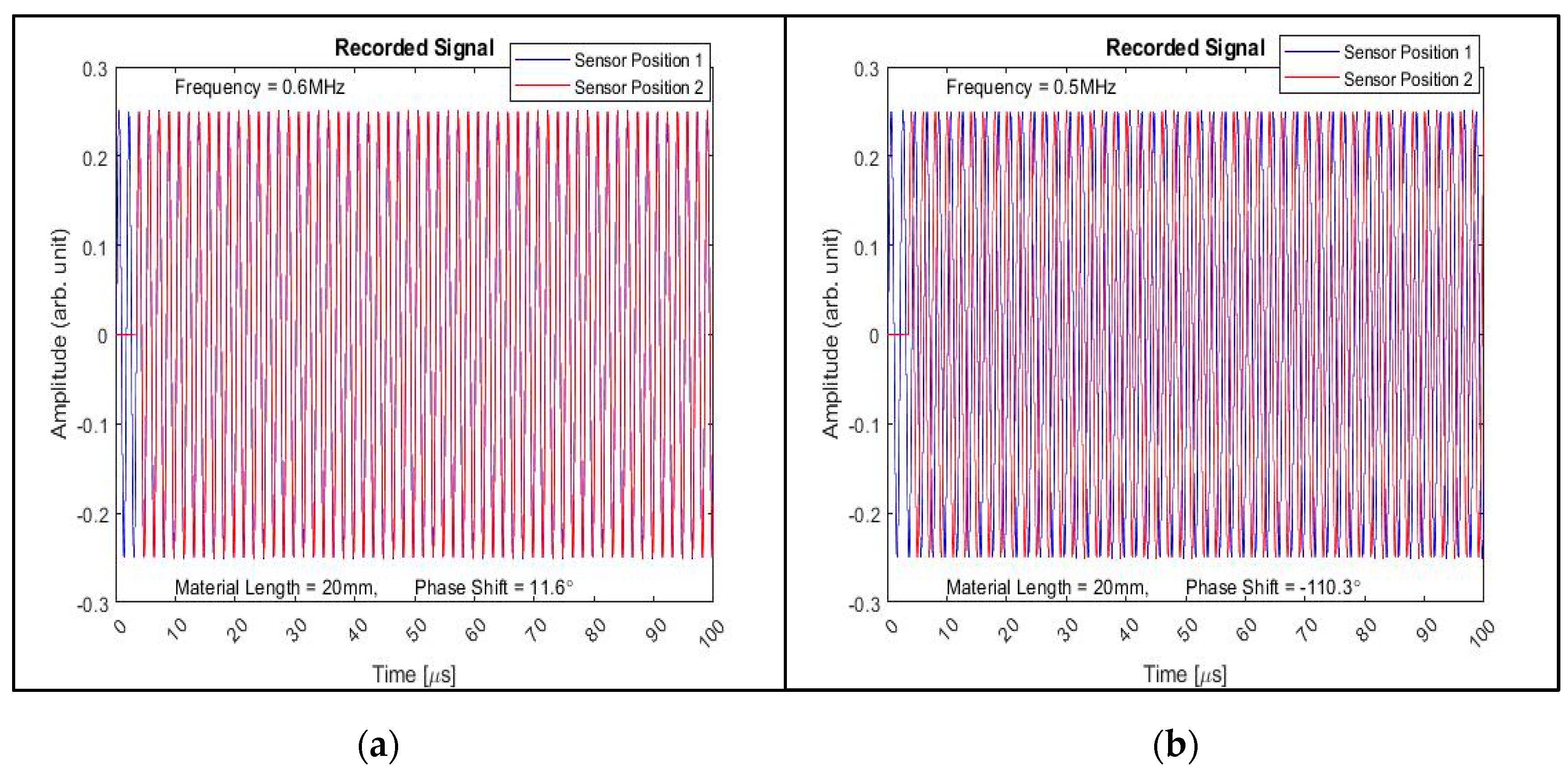
The MFcw technique was used in the third simulation for the estimation of ultrasonic velocity. First, relatively low frequencies of 0.6 and 0.5 MHz were used to estimate ultrasonic velocity through phase-shift—this is the TFcw technique. Thereafter, based on Equation (3), 0.5, 0.51 and 10 MHz were used to improve the sensitivity of the simulation for a 0.1 °C change in temperature (MFcw). The results for the simulations are given in the
Figure 4a,b and
Table 3 respectively.
The result of the simulation with 5 MHz transducer and 15 mm steel plate is given in
Figure 5.
From the results of the simulations, both the pulse-echo method and the phase-shift method were able to resolve 0.1 °C change in temperature. However, a pulser/receiver is needed to use the pulse-echo method. For a 0.1 °C change detection, the pulser/receiver needs samples at up to 10 GHz and the cost of such device can reach the €20,000 mark. However, for the phase-shift method, the cost of a phase detector is under €400. The phase-shift method was chosen because of its cost effectiveness, therefore, the experiments described in
Section 3 are all based on the phase-shift method.
5. Conclusions
This study showed that an ultrasonic measurement of the speed of sound in a metal based on the phase-shift method can be used to obtain the core temperature of the metal with a resolution of up to 0.1 °C. Based on simulation results of the two main ultrasonic measurement techniques—the pulse-echo and the phase-shift techniques—phase-shift is the less expensive technique for high resolution ultrasonic thermometry in metals. The two-frequency continuous wave method (TFcw) and multiple frequency continuous wave method (MFcw) are two improvements on the general phase-shift method for longer range and finer resolution measurements. A simulation was performed to observe the individual effects of expansion and change in ultrasonic velocity on time-of-flight. Based on the simulation, ultrasonic velocity can be relied upon for measuring time of flight and, where necessary, compensations can be made for the material expansion. Using a 5 MHz transducer, 15 mm steel plate and varying the temperature from 20 to 30 °C, a voltage equivalent of phase difference was obtained. Overall, the results demonstrate that phase-shift ultrasonic thermometry can be used for core temperature measurement with a resolution of 0.1 °C. A possible application of this study would be for temperature monitoring during co-ordinate metrology, such as on a co-ordinate measuring machine. As part of future work to deploy this setup in subtractive manufacturing, more experiments will be undertaken to understand the effects of swarf and coolant on ultrasonic thermometry. Future experiments will also be carried out to understand the effect of temperatures above 200 °C on ultrasonic velocity. Also, as different materials have different physical properties, ultrasonic thermometry must be calibrated for the material of which the measurement is to be made. Future work will also address the possibility of using ultrasonic thermometry to measure the temperature of a region or a point within different materials. The use of switching algorithms to different frequencies for different materials and material sizes will also be researched.


