1. Introduction
Technical progress demands more capable surfaces for a lot of applications with highly-loaded components that can withstand a variety of tribological, mechanical, and chemical stresses [
1,
2]. In order to increase the service life time of such components, there are a number of technological approaches, e.g., microfinished guide pads for BTA deep hole drills (BTA: Boring and Trepanning Association) [
3,
4]. One possibility to reduce the wear of tribological functional surfaces is the application of so-called wear protection layers by coating processes [
5,
6,
7].
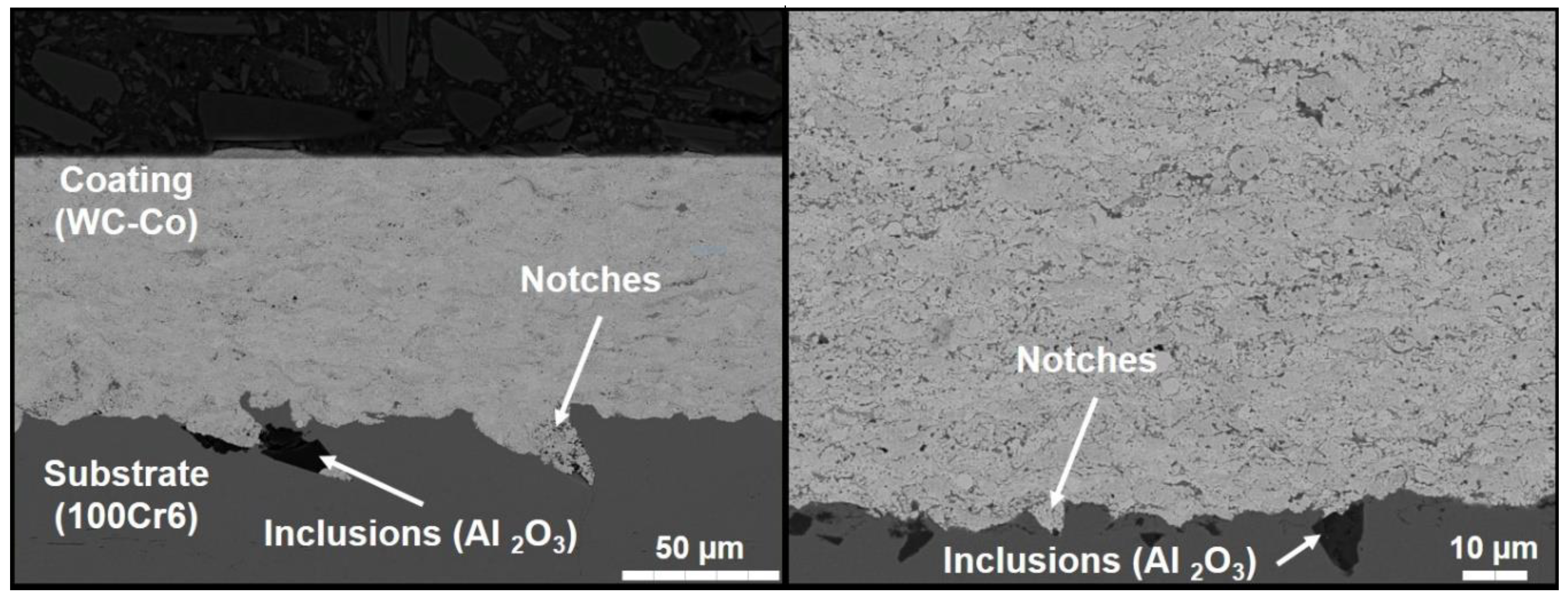
Thermally sprayed coatings are characterized by high resistance to wear, cavitation, corrosion, and thermal loads. In real applications, the coated components are often subjected to stress collective that includes, in addition, dynamic stresses. For this reason, the dynamic strength must be considered when designing the coating of mechanical parts and components. The collective stresses have been extensively studied for uncoated parts for different materials and components. In contrast, the resistance to dynamic loads combined with an increased service life of a coating system has not yet been thoroughly investigated. The reason for this is that the dynamic behavior of a coated part and component is influenced by diverse factors that affect the bonding strength, crack formation, and propagation. Furthermore, the bonding defects (notches and contaminations caused by sandblasting) at the coating interface, cracks, and pores as microscopic and macroscopic defects in the obtained coatings would inevitably lead to the crack formation and propagation in the coated components as a result of the dynamic stresses [
8,
9,
10,
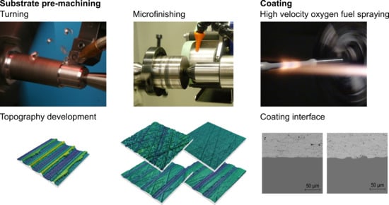
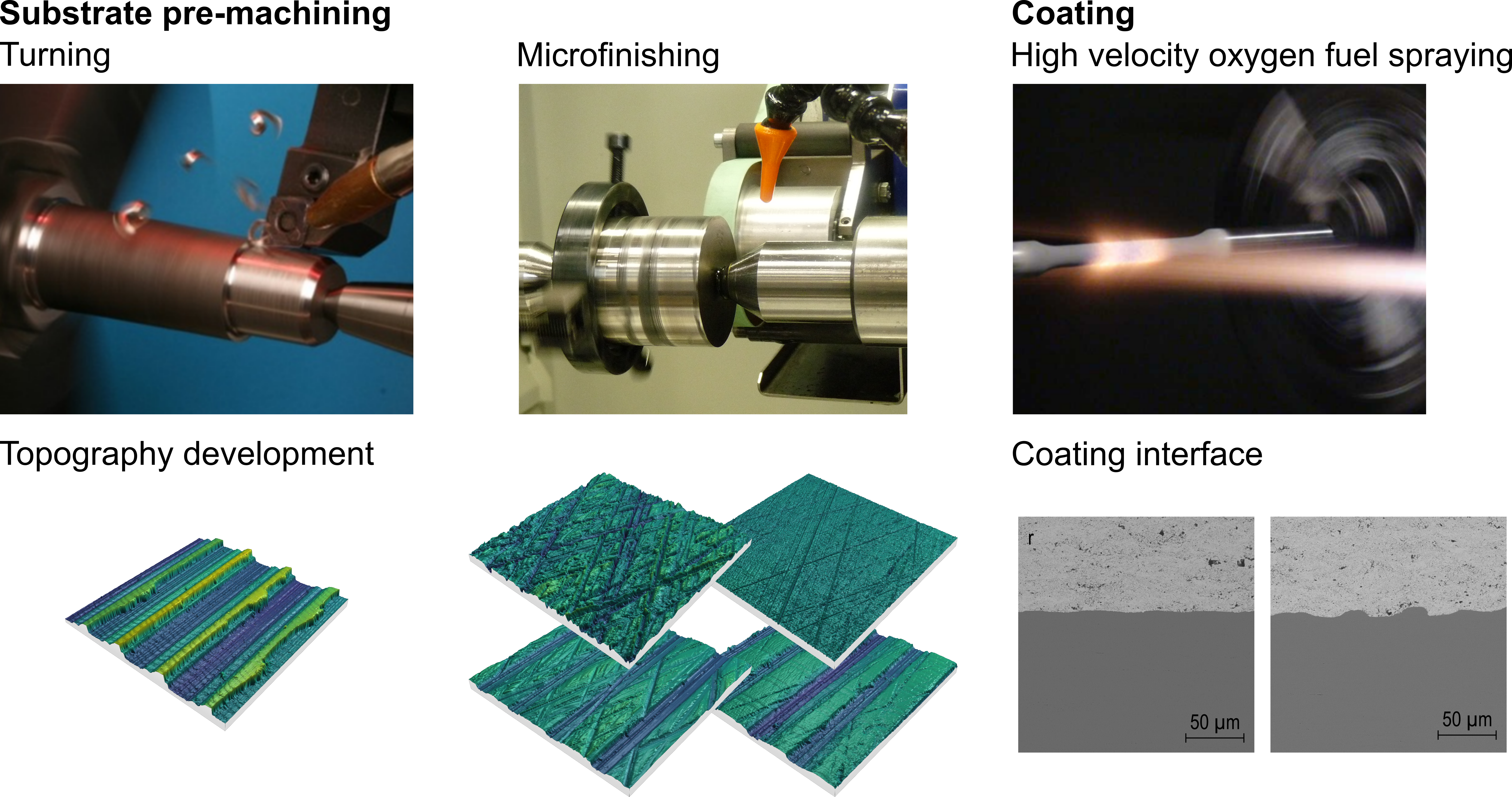
11]. The roughening of the substrate surface is an essential prerequisite to ensure a sufficient mechanical bonding of the impacted particles with the substrate surface, as shown in
Figure 1. This fact makes the generation of bonding defects in particular notches, and thus the deterioration of dynamic strength, unavoidable by using sandblasting.
The new development in the high velocity oxygen fuel (HVOF) spraying technique enables the use of fine powders as a feedstock and therefore the production of coatings with lower porosities, lower roughness, and higher adhesive strength [
12,
13]. This development may enhance, through the reduction of the microstructure defects, the dynamic behavior of the obtained coatings. However, the number, size, and distribution of the remaining defects, as well as the generated undesirable notches and inclusions, are still critical for the dynamic behavior of the obtained coating system [
9,
10]. Moreover, a number of investigations have been done in thermal spraying in order to determine the effect of the residual stresses on the behavior of the obtained coatings [
14,
15,
16,
17,
18]. The residual stresses during thermal spraying arise from three basic mechanisms: The alternating heat input during repeated passes of the spray flame, the impact of the particles, and the quenching of the spray particles on impact [
14,
19]. Sartwell et al. [
20] found that the compressive stresses reveal an improvement in the service life of the components. In general, the resulting residual stresses influence the mechanical properties of the sprayed coatings and can thus lead to a reduction in coating adhesion, dynamic strength, and wear resistance [
21,
22,
23]. The induced residual stresses, and thus their effect, however, vary depending on the hardness and thermophysical properties of the substrate material used. To study the effects of all these factors on the coating adhesion and dynamic behavior, a substrate material, with a hardness that can be adjusted over a wide range, is needed. The bearing steel 100Cr6 is, therefore, the most suitable material for the intended investigations.
The following investigations are part of a funded project with the overall objective to improve the fatigue strength of dynamic loaded workpieces. Therefore, a part of this funded project includes investigations on machining surface conditioning and bonding tests for the WC–12Co HVOF coating, which are the subjects of this paper. The main objective of surface conditioning is to improve the coating adhesion by suitable machining processes of the substrate surface. With regard to the surface integrity influenced by the machining, the residual stress on the machined surface is analyzed, in addition to the surface topography. These are not directly related to coating adhesion, but are part of the surface integrity analyses and the overall research project to increase the dynamic strength of HVOF-coated components. Since the overall aim is to improve the dynamic strength, rotational bending tests should be carried out finally. Therefore, the workpiece shape is standardized by DIN 50113.
Furthermore, in order to meet the objective of this study, the substrate surface was prepared with turning in combination with two different strategies of microfinishing. In comparison, a typically sandblasted substrate surface is additionally considered. The microfinishing can be used to roughen the substrate surface by creating a plateau patterned surface which, in comparison to sandblasting, does not lead to the adhesion defects [
7]. To prepare the substrate surface of hardened 100Cr6 (AISI 52100) steel for an HVOF coating, two roughness profile types were machined by means of microfinishing an initially turned surface. The overall objective in this study is to improve the coating interface and reduce the adhesion defects by a combination of turning and microfinishing. Therefore, the selection of suitable microfinishing parameters is in charge to produce the final substrate surface and thus affect the surface integrity.
Microfinishing, also known as superfinishing or briefly called finishing, precisely describes the process of short-stroke honing which is standardized according to DIN 8589-14 [
24]. As the name indicates, microfinishing is generally the last process along the machining process chain. It is mainly used to improve the tribological contact situation without changing the shape by influencing the surface topography and, thereby, its microscopic topography [
25]. The tools used can be solid stones or flexible microfinishing belts or films. Both are built out of bonding material and abrasive grains. Typical grain types are diamond (D), corundum (Al
2O
3), and silicon carbide (SiC), with grain sizes between
dK = 1 and 125 µm [
7,
26].
Microfinishing is a honing process and the kinematics are similar and thus characterized by a rotation of the workpiece and a superimposed orthogonal oscillation of the tool. Generally, the oscillation frequency during microfinishing can be up to
fOs = 21 Hz, and a maximum amplitude up to
A = 3 mm [
25]. This is equivalent to a width of oscillation of
lOs = 6 mm. Due to this short stroke width, microfinishing is also called short-stroke honing. The process kinematics of workpiece rotation and tool oscillation lead to the movements of tangential speed
vt and axial speed
va, which can be summarized to the resulting cutting speed
vc [
7,
26]. Thus, the cutting speed can be calculated by Equation (1):
By implementing several microfinishing steps with subsequently decreasing grain size, typical microfinished surfaces can be produced [
7]. The first microfinishing step, rough microfinishing, is generally used to remove the typical initial ground surface by reducing the profile peaks and generating crossing honing grooves. Due to the material removal mechanisms, lateral bulges often appear along the honing grooves. These should be removed within the further process steps, the so-called fine microfinishing. The resulting surface has a typical microfinished plateau topography characterized by homogenous valleys in a cross-grid pattern and flat areas or plateaus without profile peaks [
2,
3,
7]. In addition, these surfaces have a high bearing area ratio. The material removal mechanisms that influence the roughness and bearing surface ratio are determined by the tool specifications, process parameters, and workpiece properties [
2,
7,
27,
28]. The material removal mechanisms in microfinishing processes can be assumed as an interaction of mechanisms like microcracking and microfatigue, and mechanisms of microridging, microploughing, and microcutting, analogous to longitudinal stroke honing processes [
26,
29,
30,
31,
32].
Due to tool selection and process parameters, the material removal volume can be controlled and the microfinishing process enables surface conditioning in distinct ways. Regarding the small material removal ratios, it is possible to change the initial surface topography without removing the complete topography. This possibility has been used to generate combined surface topography combining the features of an initially milled and a microfinished surface topography [
2,
7].
Due to the effect of low material removal while microfinishing, it is used for these investigations as substrate pretreatment for a high performance multilayer component. The goal is to generate a homogenous topography which improves the coating’s interface. Therefore, different surface topographies based on a turning topography should be produced. On the one hand, the initial surface topography is partly removed. On the other hand, the turned surface topography should be removed completely, thus a microfinished plateau topography occurs.
2. Materials and Methods
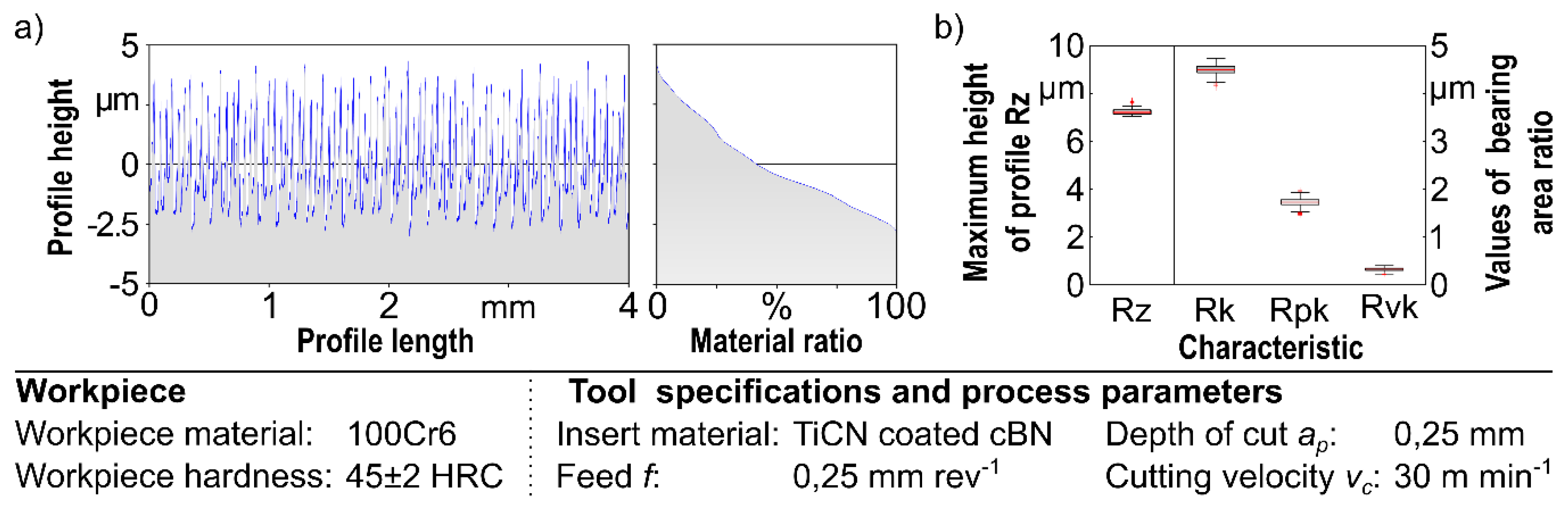
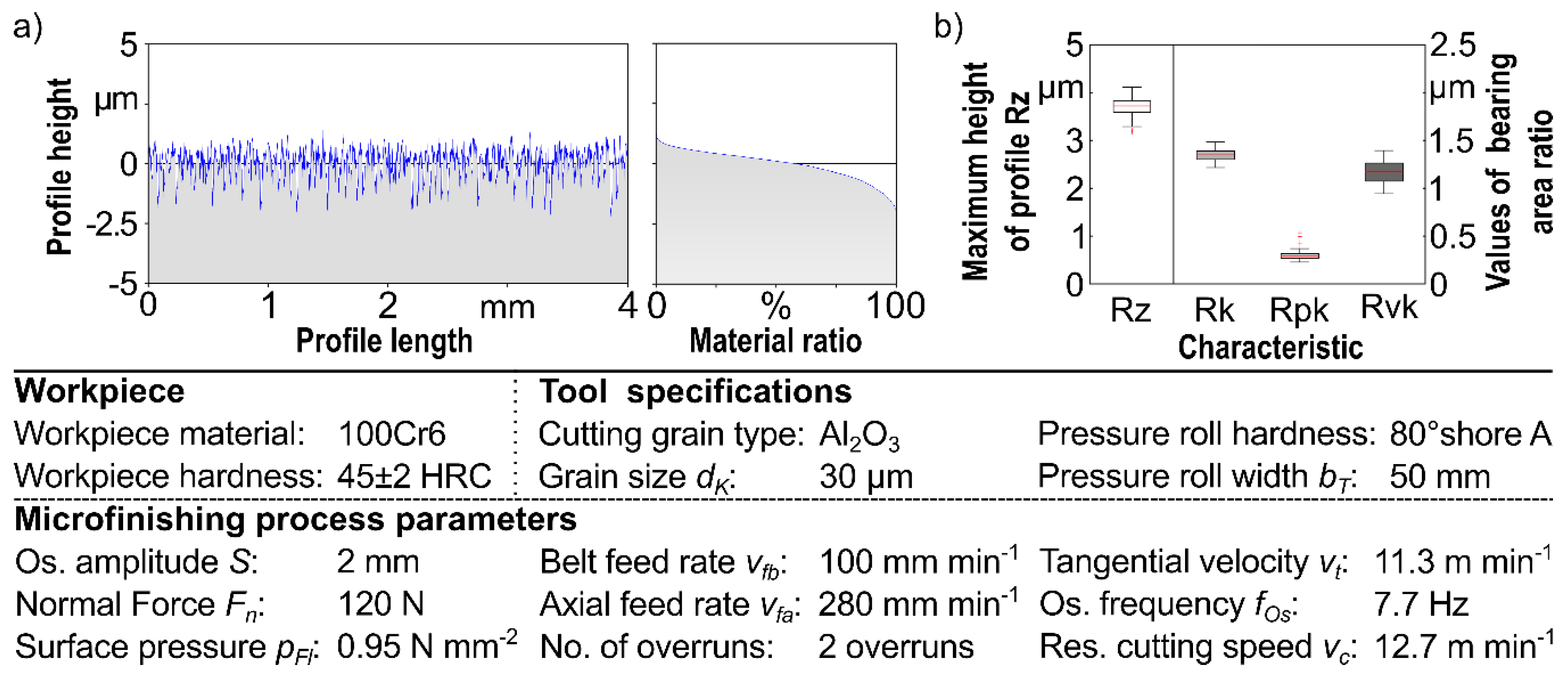
For the investigations, 100Cr6 (AISI 52100) steel bars with 13 mm diameter and a length of 226 mm were used as substrate. The bearing steel was heat treated to a hardness of 45 ± 2 HRC and straightened afterwards. The initial surface for both microfinished surfaces was the same turning topography as shown in
Figure 2. The turned topography is depicted by an exemplary extract of the profile and its material ratio curve in
Figure 2a. Additionally,
Figure 2b shows a boxplot diagram build by the measured values of the maximum profile height Rz, the core roughness Rk, the reduced peak height Rpk, and the reduced valley depth according to the international standards DIN EN ISO 4287 and DIN EN IS0 13565 [
33,
34].
These measurements were done using a confocal white-light microscope Nanofocus µsurf C with an optical module 320 S. In accordance with DIN EN ISO 4287, the suitable measuring section and the corresponding filtering system were used for the evaluation of the roughness and material content parameters. Further information on the measurement system and the evaluation strategy is given in
Table 1.
Based on the area measurements, 250 profiles were used for each evaluation of the surface characteristics. The boxplots shown in the images can be created from this. The boxes contain 75% of all measured values, and the median is shown as a red line. The whiskers mark the maximum or minimum measured value. Values that are more than 1.5 times the box height distance from the box’s upper or lower limits are marked by the statistics software MatLab used for evaluation as outliers. These are shown as red crosses.
The turned surface shown here is characterized by its typical periodic profile and nearly linear falling material ratio curve. The maximum peak height of the turned initial surface is about Rz = 9 µm. According to ISO 13565-2 [
34], the values of bearing area ratio should only be calculated for “S”-shaped material ratio curves. The illustration of the characteristic values at this point therefore only serve as a completion with regard to later figures. However, the consideration of the characteristic values as such according to DIN EN ISO 13565-2 for the turned surface is not expedient.
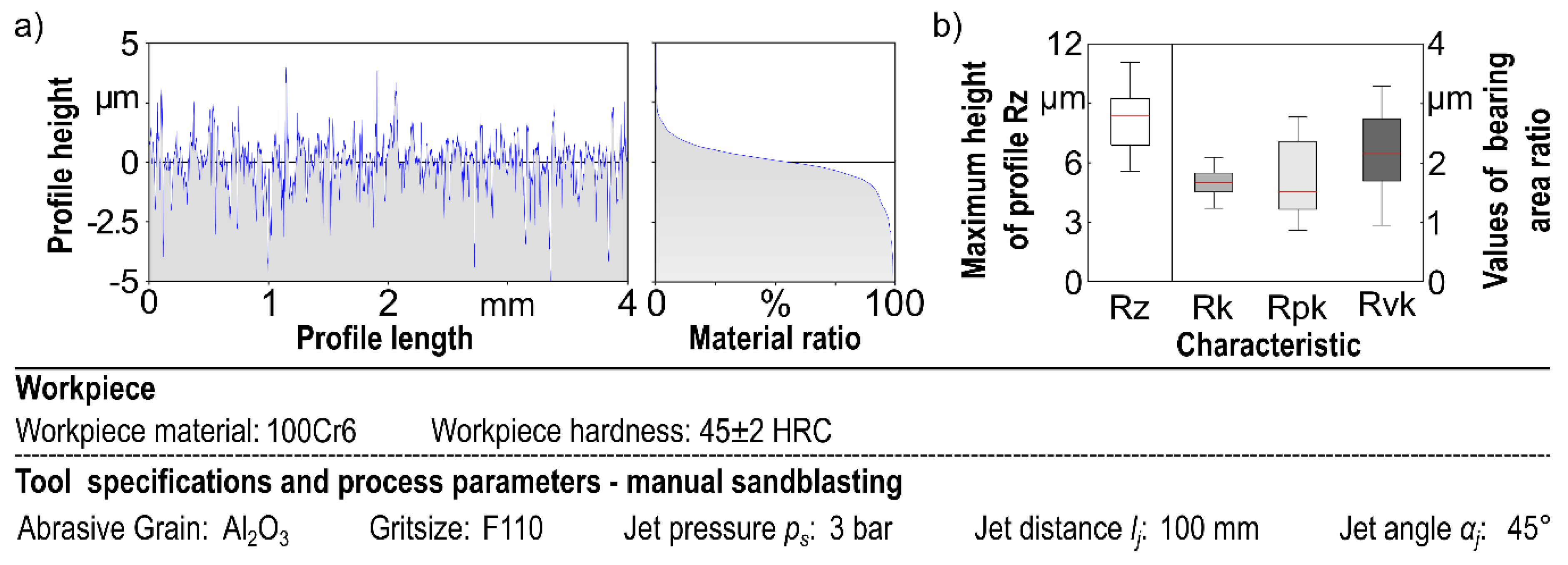
In comparison,
Figure 3 shows a profile, material ratio curve as well as the surface values for a sandblasted surface. It becomes particularly clear that the surface has a higher roughness due to sandblasting and does not have a homogeneous repeating structure.
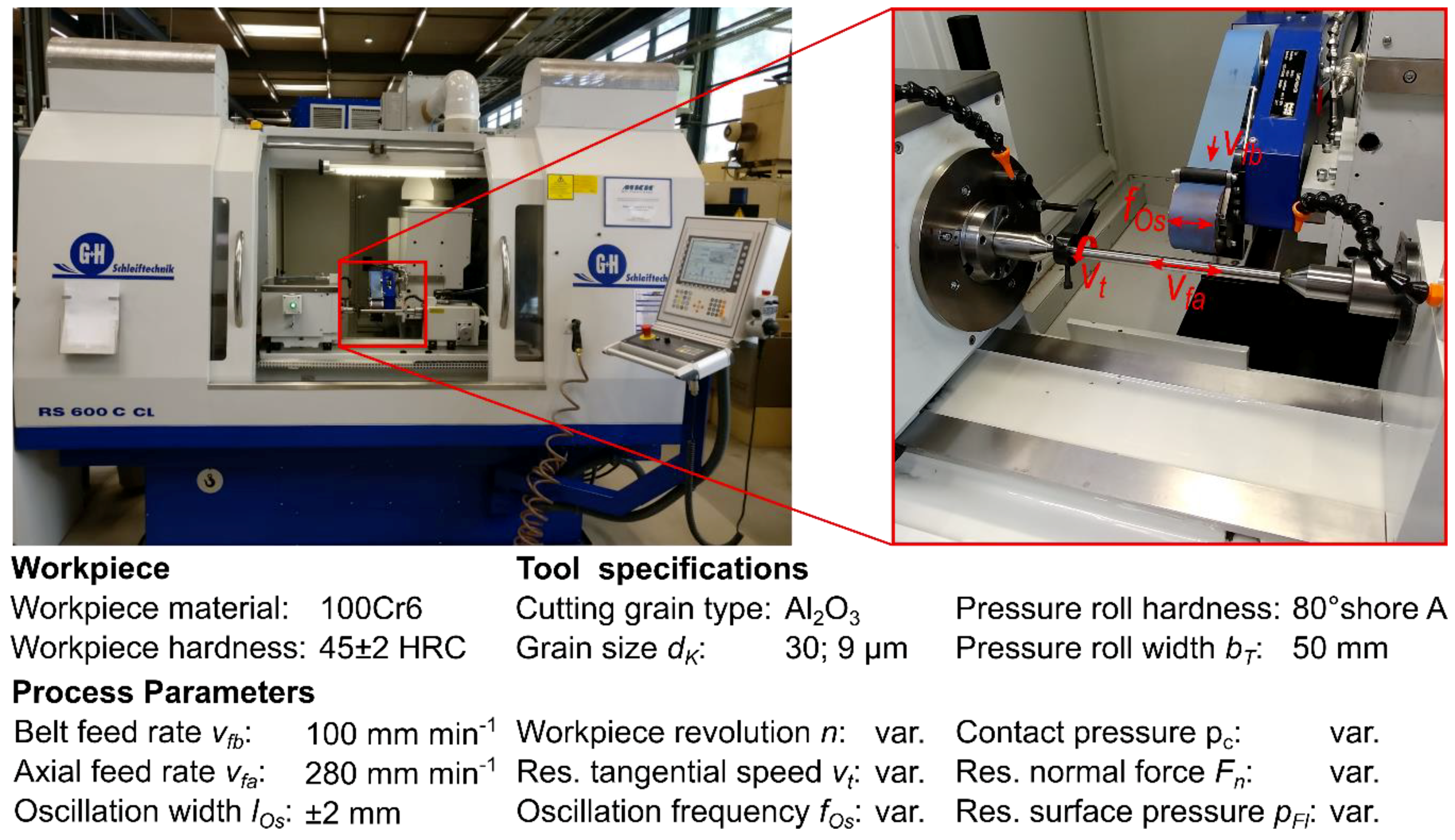
The microfinishing of the turned surface was carried out on an RS 600 C Cl cylindrical grinding machine from Geibel & Hotz Maschinen und Werkzeuge GmbH. For this purpose, the NBFG 5 belt-finishing device from NAGEL Maschinen- und Werkzeugfabrik GmbH, implemented in the machine control system, was used.
Figure 4 shows the external round lathe within the belt-finishing device and the machining movements for microfinishing.
The infeed movement of the microfinishing belt at the beginning of the process was achieved by the air pressure inside a cylinder, whereby the piston performed the tools infeed in normal direction of the workpiece. The constant pressure inside the cylinder during machining resulted in a force-controlled process with the normal force Fn.
The microfinishing was carried out without any cooling, as the microfinishing is a so-called cold process and microfinishing belts do not require any lubricant at constant belt feed. To ensure the production of different surface topographies and to alternate the induced residual stresses by using similar initial surfaces, different strategies for microfinishing were used. On the one hand, the “fine” microfinishing strategy with a resulting cutting speed of
vc = 25.5 m min
−1 was combined with a number of six axial overruns on the workpiece. On the other hand, the so-called “rough” microfinishing strategy was carried out within a cutting speed of
vc = 12.7 m min
−1 combined with only two axial overruns. For both strategies, two microfinishing steps were realized with the aim to produce patterned honing grooves and a plateau surface and, in the case of rough microfinishing, some plateau areas. The tool was varied for each microfinishing step by using different grainsizes and orientations. In the case of the first finishing step, a microfinishing belt with Al
2O
3-grains, grain size
dK = 30 µm, was used. These grains are electrostatically-oriented, so they can produce a relatively high material removal. A tool with gravity-scattered Al
2O
3-grains with the size of
dK = 9 µm was used for the final microfinishing steps in the case of fine and rough microfinishing. An overview showing the different parameters for all microfinishing steps of both strategies, fine microfinishing as well as the rough microfinishing, is given in
Table 2.
A Computerized-Carbide Jet System K5.2 (C-CJS K5.2) from Thermico GmbH was used to deposit the HVOF–WC–Co coatings. A commercially available WC–12Co (Woka 3102, Oerlikon Metco, USA), agglomerated and sintered spheroidal powder with the grain size of
dK = −45 + 15 µm, was used as feedstock powder. The spray parameters, which were used for the deposition, were determined in preliminary tests and are listed in
Table 3. These parameters are capable of producing optimum coatings with low porosity, high homogeneity, and relatively smooth surface.
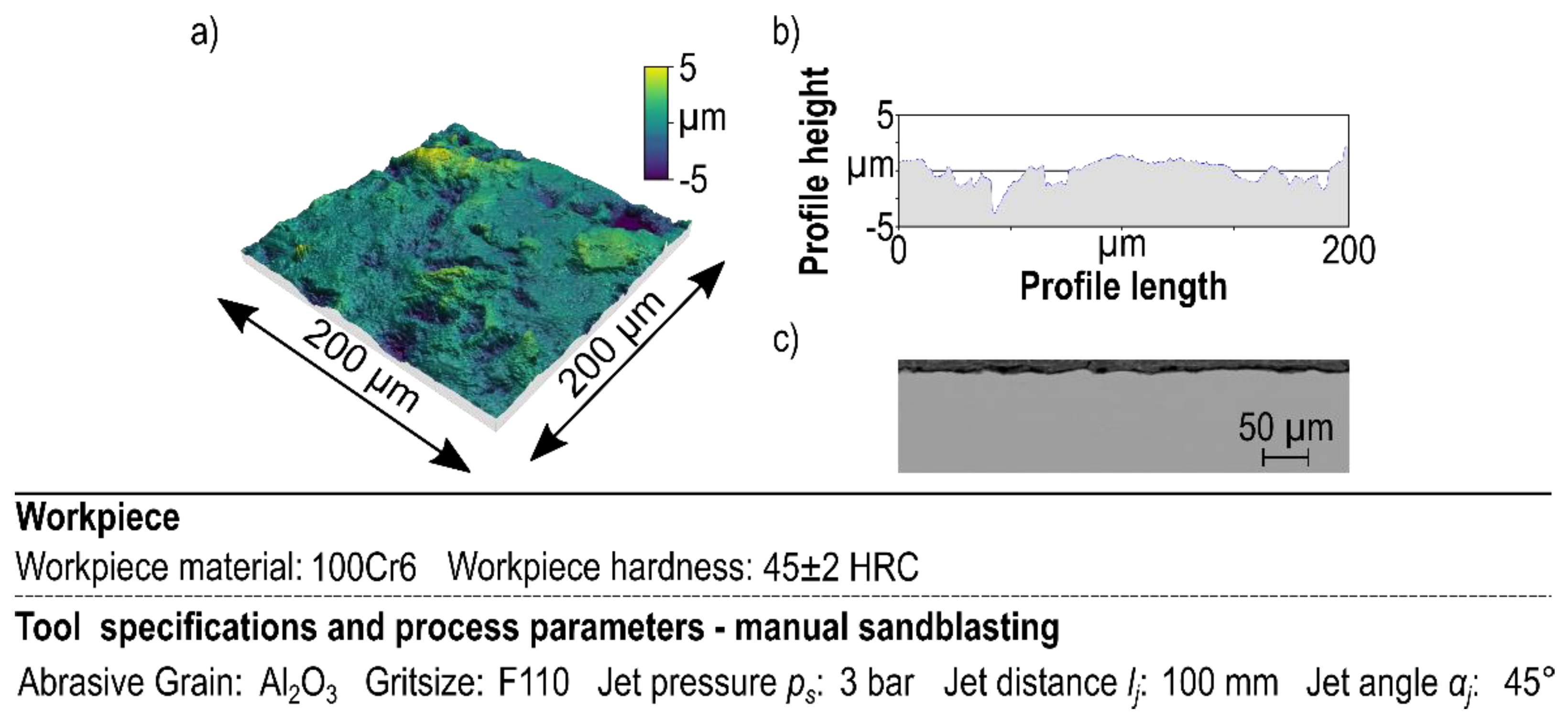
The surfaces of all substrates that had not been machined were roughened by sandblasting using F110 Al2O3 grains. The jet pressure of the blasting gun was set to pjet = 0.3 MPa, and the distance was kept to 100 mm at a jet angle of 45°. The blasting time was approximate 45 s for each substrate surface.
The phase composition of all samples and the obtained coatings were investigated by an X-ray diffraction (XRD) device using Cr-Kα1. All measurements were done by using LYNXEYE XE detector (Bruker Advanced D8 diffractometer). The induced residual stresses of the turned and microfinished substrates were determined by the same device. The measurements were done for 2θ 106.6° (Fe 2 0 0). The investigated range of high diffraction angle 2θ is between 103.5° and 108.5° in a step size of 0.1° and 3.5 s scanning time. The Phi angle was used at 0° and 180°, while Chi was varied between 0° and 60° in eight steps. The residual stresses were calculated based on the changes in the distance of a lattice plane for different inclination angles (ψ). For the calculation of the residual stresses, a Poison ratio of 0.3 and a Young’s modulus of 210 GPa were used. Additionally, the used elastic constants were S1 = −1.429 × 10
−6 MPa
−1 and 1/2S2 = 6.190 × 10
−6 MPa
−1. The distance change as a function of inclination angles was analyzed with the Bruker software Leptos, and the exact values of the residual stresses were determined using the sinψ method according to [
35,
36].
3. Results
This chapter shows the results of the experimental investigations within different figures depicting diagrams, cross section pictures, and topography measurements as well. In addition to the presentation, the influence of the machining processes on the surface integrity were analyzed as far as possible.
3.1. Resulting Surfaces for the Fine Microfinishing Strategy
In this section, the results of the fine microfinishing experiments are shown and analyzed as well. With the aim of producing a plateau finished surface, the turned surface was machined with two steps of microfinishing at a cutting velocity of
vc = 25.5 m min
−1. In order to achieve a high material removal rate to remove efficiently particularly the peaks of the turned topography, the process pressure was chosen as high as possible.
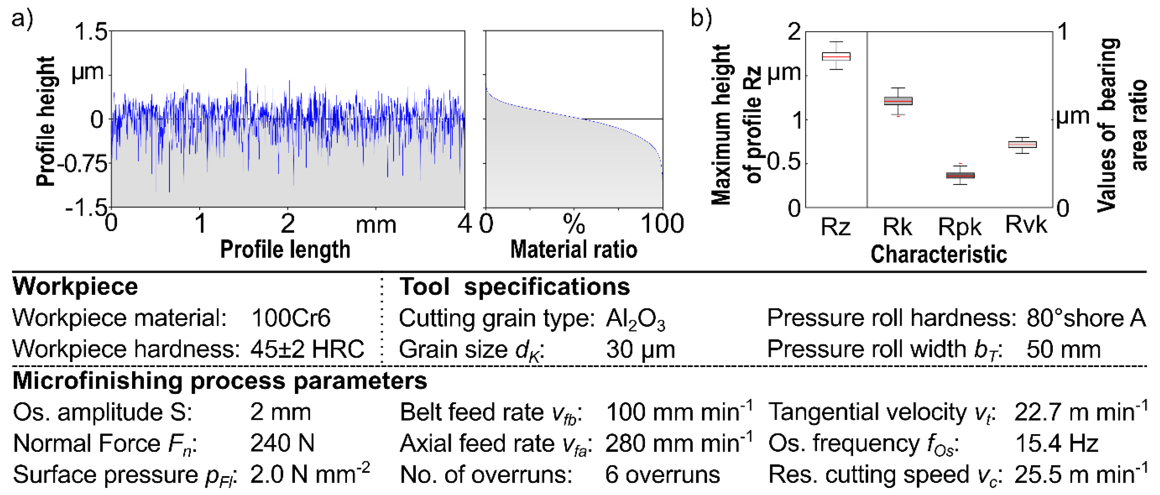
Figure 5 shows the profile material ratio curve and some surface values for the first step of fine microfinishing.
As can be seen in
Figure 5, the periodic profile of the initially turned surface is no longer apparent. The profile appears rather aperiodic and is characterized by many low and high points within the scale. A closer look reveals that the negative values dominate, which means there are more grooves than peaks.
The material ratio curve is now described by different gradients and is approximately “S”-shaped. Thus, the values of bearing area ratio can be analyzed, as well as the maximum peak height of the profile. Compared to typical microfinished surfaces, a maximum peak height of the profile Rz up to 1.8 µm can be described as high. Taking the grain size and the electrostatic grain orientation into account, this is a typical Rz-value, especially when it is not the last microfinishing step. Although, the median Rvk to Rpk ratio is approximately 1.8, this surface is not a plateau topography. This can be confirmed by the consideration of further parameters, since the sole consideration of the RVK/Rpk ratio is not sufficient to define a plateau topography. The core roughness Rk is relatively high, respectively significantly higher than Rvk. This is a criterion for the fact that the surface at hand cannot be regarded as a plateau. In conclusion, the first step of fine microfinishing produces an aperiodic surface with a higher amount of valleys in comparison to peaks. However, peaks still appear, thus a second microfinishing step is necessary to produce a plateau-textured surface.
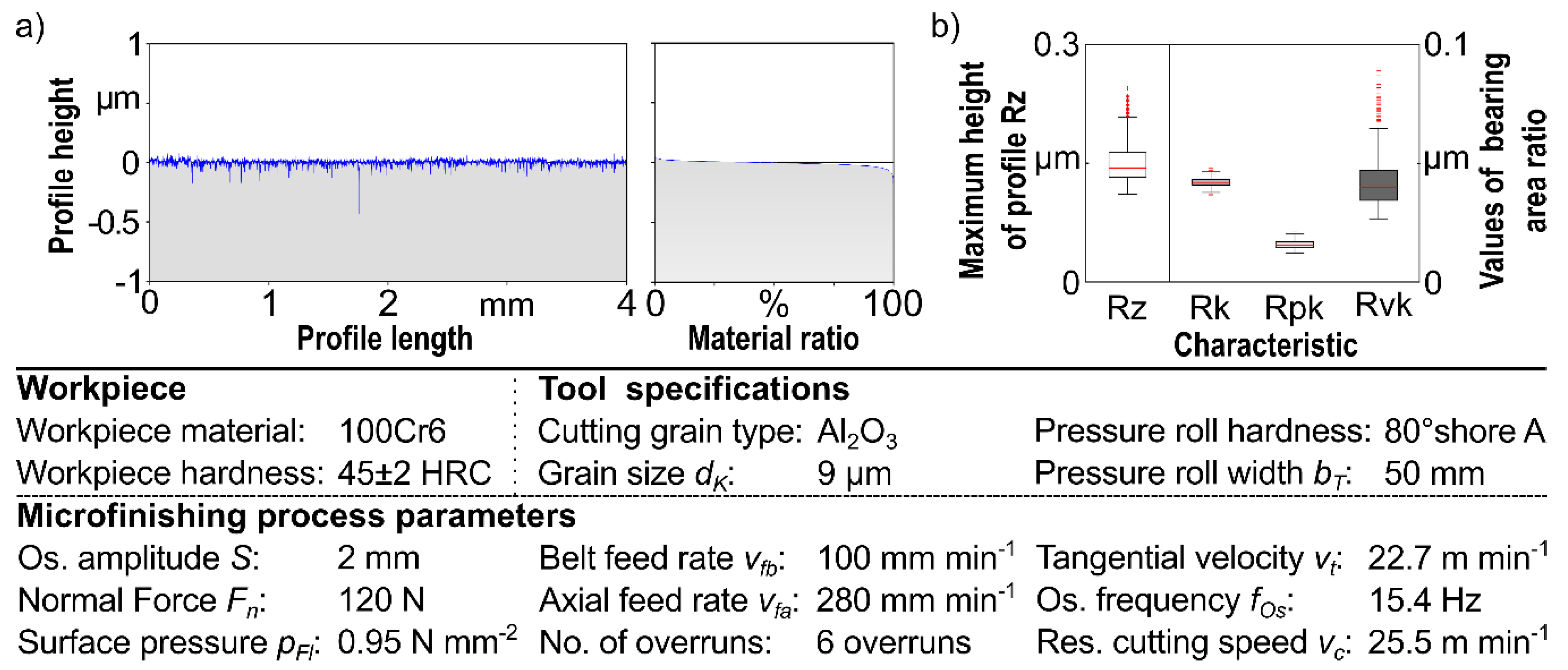
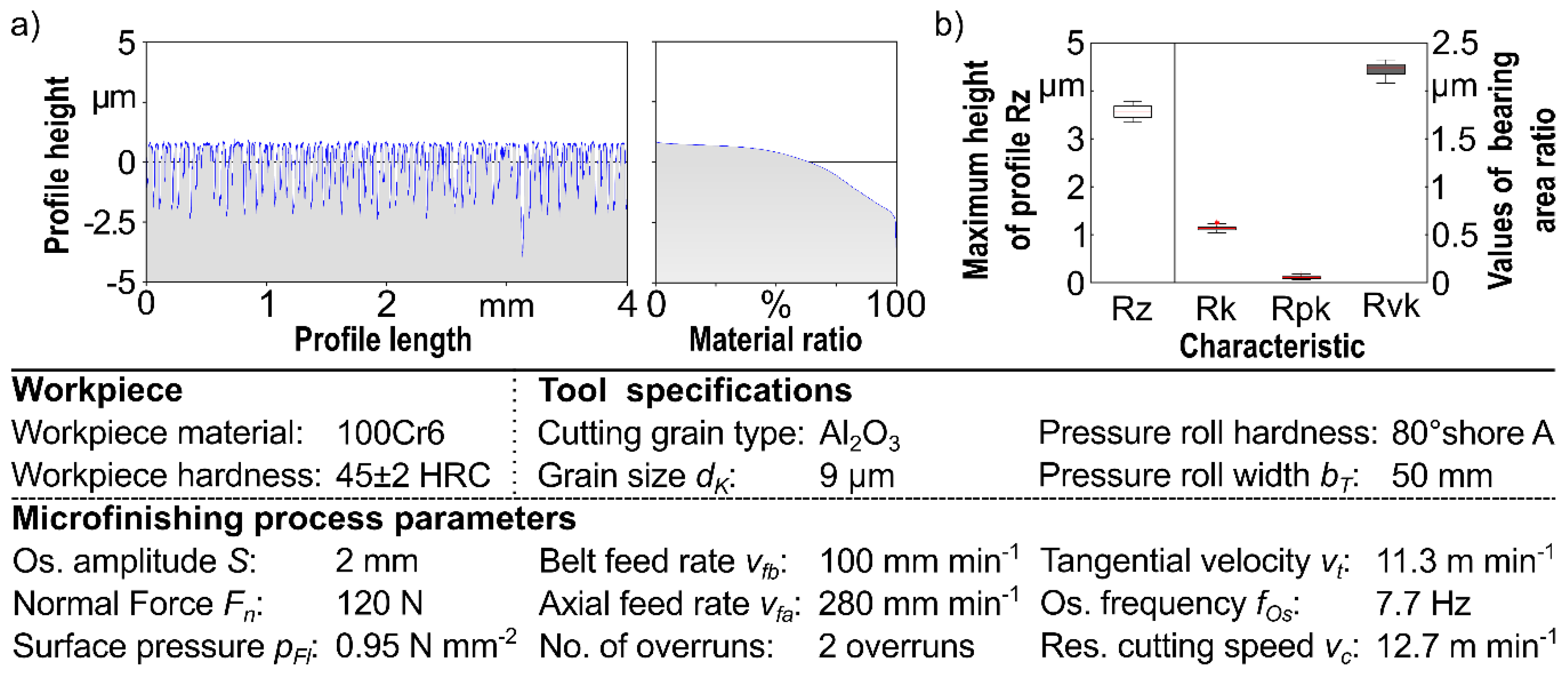
Figure 6 shows the same graphs and diagrams with respect to the surface of the second fine microfinishing step. In this case, the scale for all graphs and values decreases from the first to the second step because the surface is smoothed.
The profile appears as smooth surface within frequent small cavities and nearly no peaks. There is one dominant cavity outstanding with a depth close to 0.5 µm. The material ratio curve is characterized by a huge flat area and its “S”-shaped form. The maximum height of profile Rz is reduced from the first microfinishing step by the secondary microfinishing step to values between Rz = 0.2 up to 0.45 µm. In comparison to the first microfinishing step, the values of bearing area ratio now describe a plateau-textured surface. The reduced valley depth Rvk is significantly higher than the reduced peak height Rpk (for the median values Rvk/Rpk approximately 2) and, additionally, the core roughness Rk is relatively low. In summary, it can be stated that after the second fine microfinishing step, a smooth plateau surface with very small valleys is achieved.
3.2. Resulting Surface for the Rough Microfinishing Strategy
Starting with the first rough microfinishing step,
Figure 7 depicts the profile curve and the material ratio curve (a), as well as the characteristics of the surface described by Rz, Rk, Rpk, and Rvk. Analogous to the processing steps of fine microfinishing, the results of rough microfinishing are now presented.
Considering the profile resulting from the first rough microfinishing step, it is apparent that the initial turning topography is not completely removed. The profile remains periodic, whereby the peaks and valleys are not as high as before, compared to
Figure 2. With respect to the measured values, the surface is not plateau-textured, even if the ratio of Rvk/Rpk is greater than 1. The microfinishing process leads to a reduction of the peaks of the turned surface. The parameters, especially the cutting frequency and the number of overruns, are sufficient to generate a surface where periodic elements of the turning process remain.
Subsequent to the first rough microfinishing step, the second step was performed using a gravity-scattered 9 µm Al
2O
3 microfinishing belt. The resulting profile, material ratio curve and the surface values are summarized in
Figure 8.
The profile is smoothed and the highest elevations appear less peaked than before. There are dominant cavities which have a depth of around 3 µm when measuring from the top of the profile. The smoothed profile appearance on the top is also reflected by the material ratio curve. Taking the first 50% material ratio into account, the curve is nearly the same as the final fine microfinished surface. Even if the material ratio curve is not “S”-shaped in this case, an analysis of the values of the bearing area ratio seems appropriate. The remaining surface has a maximum profile height of Rz = 3.5 to 4 µm and thus is not describing a smooth surface. The ratio of Rvk/Rpk is nearly 10, while the core roughness is also significantly lower than the reduced valley depth. This relation describes a plateau-like texture, although the material ratio curve is not “S”-shaped. The elevated parts of the surface are plateaus, while the remaining turning topography can be indicated by the deep cavities.
3.3. Residual Stresses
In addition to the surface measurements, the residual stress σ was measured for every machining state. Because of the shape and diameter of the workpieces, it was not possible to measure the residual stress curve by means of borehole method. That is why the X-ray-diffraction method was used to measure the residual stress in the workpiece surface.
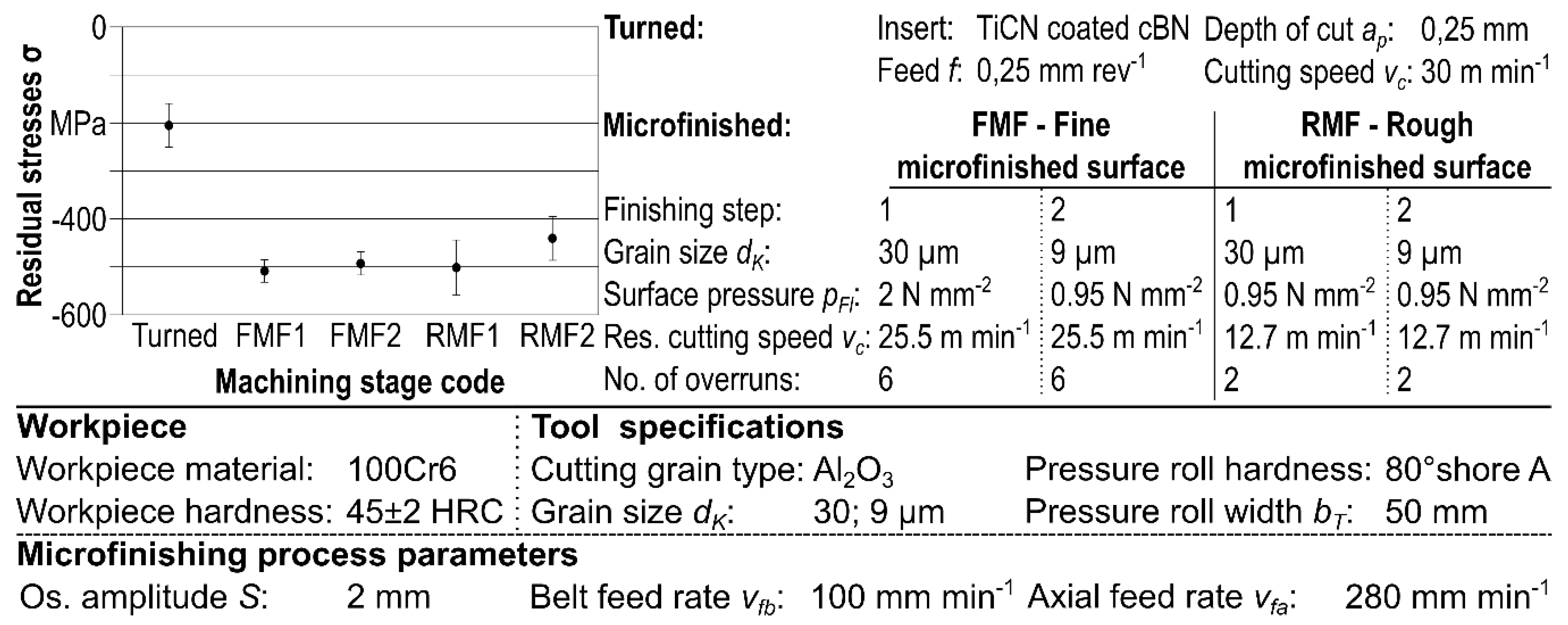
Figure 9 shows the measured residual stresses along the machining steps.
Here, it is noticeable that the induced residual stresses by turning the workpiece are compressive stresses of σ = −200 MPa. An increase of the induced compressive residual stresses σ = −500 MPa was recorded after the different microfinishing steps. The variation of grainsize and grain-orientation for the different microfinishing belts, as well as the exerted surface pressure while fine finishing, have no effect on the induced residual stresses.
Regarding the different parameters in the first microfinishing step of both strategies, fine and rough microfinishing, it is not possible to explain how each one influences the residual stress. In the case of simultaneous change of the surface pressure, the cutting velocity, and the number of overruns, the factors may interact, so the resulting residual stresses are the same. In the case of the second microfinishing step, it is assumed that the relatively low material removal due to the small grit size does not further influence the residual stresses.
3.4. Detailed Analysis of the Topography Modification
The obtained surface patterns were analyzed by 3D-topographical depictions of 200 × 200 µm combined with an exemplary profile of 200 µm length. In addition, for each machining step, a cross section was generated and inspected with a scanning electron microscope (SEM).
Figure 10 shows these analyses for the sandblasted workpiece.
For the sandblasted topography, the irregular appearance of the roughened surface is clearly visible—especially due to the wider cavities or notches, the surface appears fissured. It becomes clear that no patterning of the surface has been achieved, and therefore no homogeneous topography is present.
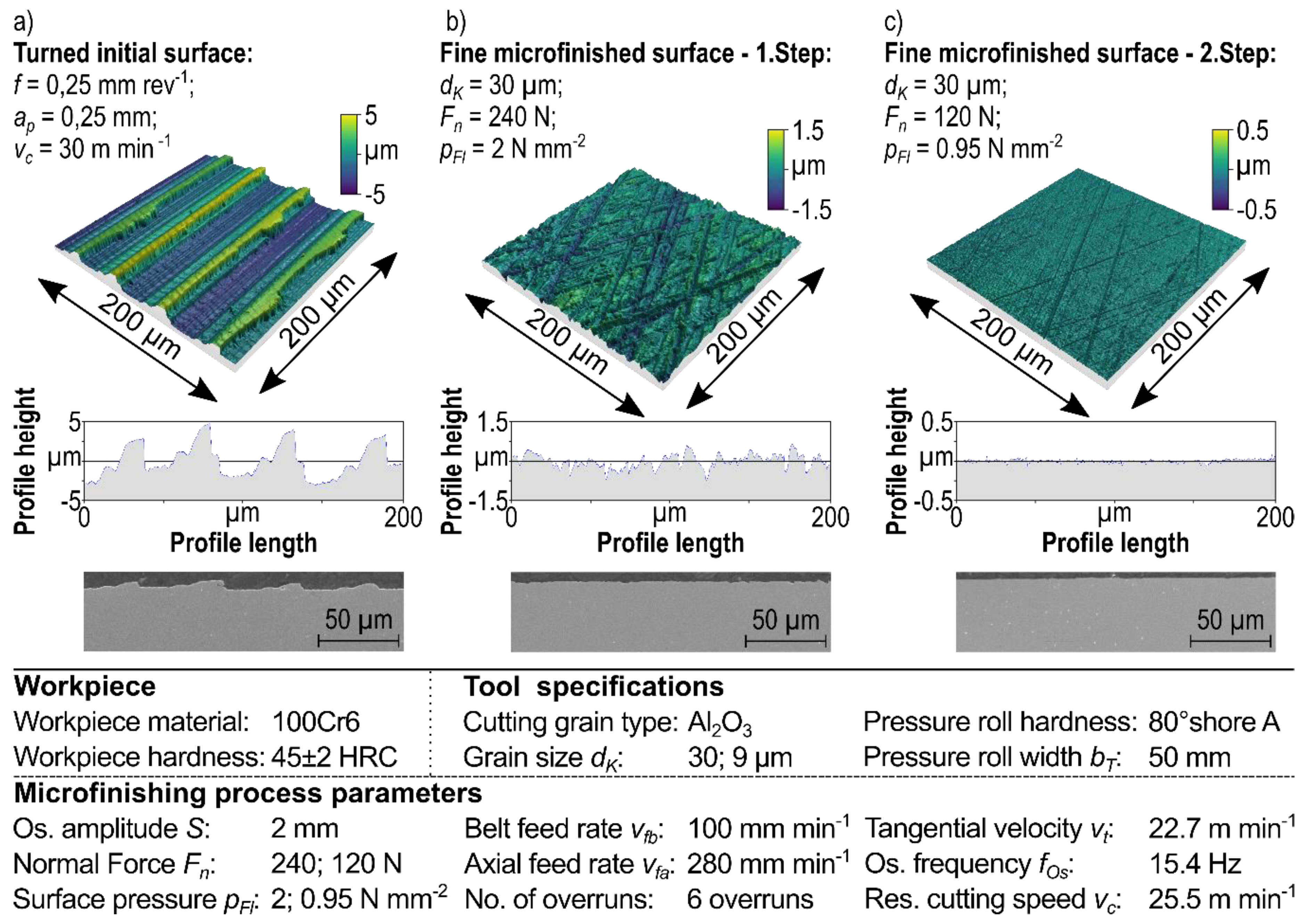
For the machining strategy of turning and microfinishing, the development of the surface topography is represented for the individual machining steps. For this purpose, for fine microfinishing, the initial surface topography, a profile writing, and the SEM image after (a) turning, as well as the modified topographies after (b) one and (c) two fine microfinishing steps are shown in
Figure 11.
This figure shows that the turned surface pattern is completely removed by the first fine microfinishing step. In addition, the 3D-topography shows the cross-angled microfinishing grooves which are created by the process kinematics. Due to the used microfinishing tool for the first step, lateral bulges appear next to the grooves. These bulges are typical for the first microfinishing steps, according to microgrooving and microploughing material removing mechanisms being effective while microfinishing. By using a second microfinishing step, these lateral bulges can be removed and a smoothed topography is generated. When comparing the profile extractions from the microfinishing steps, it becomes clear that the second microfinishing step also removes most of the grooves of the first step. This is why the remaining grooves are not as dominant and the ratio of Rvk/Rpk is not as high as possible. To increase these ratios, it might be sufficient to reduce the process time, i.e., in this case, reduce the number of overruns.
The comparison of the cross section displays the smoothening of the surface as well. The SEM magnification, in this case, seems insufficient to show the small honing grooves generated by microfinishing. Analogous to this,
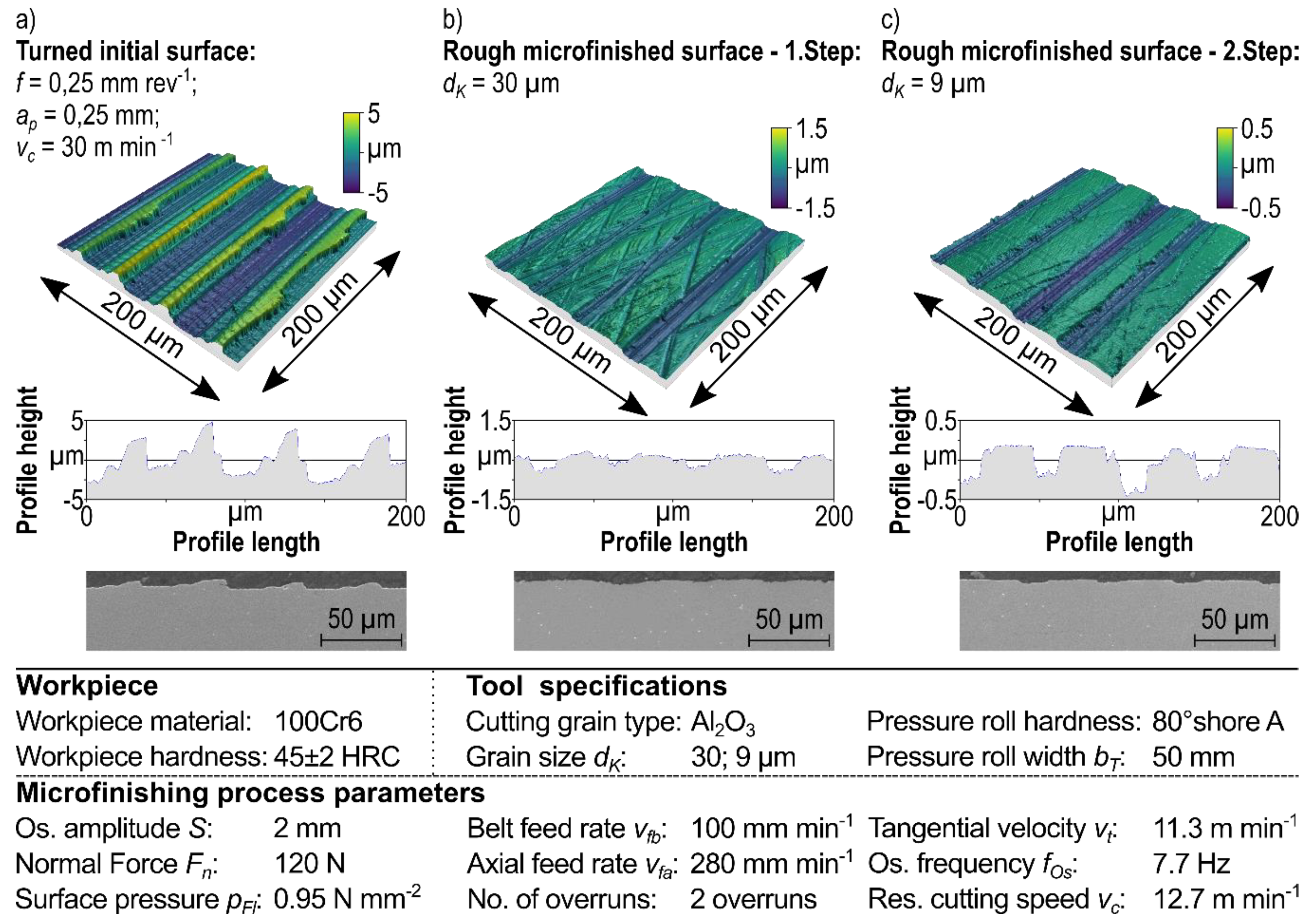
Figure 12 shows the topography and an extracted profile, as well as a cross section for the rough microfinishing.
The changes of the previously described surface based on the two-dimensional profile and the characteristic values and the material ratio curve can be illustrated by the 3D-topography, as well as the detailed profile extract and the cross section. The figure clarifies that the turning topography is modified without being completely removed. The first rough microfinishing step leads to a reduction of the peaks, since only the highest located material is removed from the surface. The contact between workpiece surface and the tool is an area whose size is dependent on workpiece diameter, microfinishing belt, and especially the contact pressure element’s dimensions and hardness. Due to the elastic deformation of the tool, there is an embrace and thus surface contact between tool and workpiece. In combination with the small grit sizes and the microfinishing kinematics, it is possible to remove material step-by-step from the highest level to the lowest with microfinishing.
Analogous to the first fine finishing step, the first rough microfinishing step generates cross-angled grooves. Here the grooves are discontinuous, since the abrasive grain only cuts the highest surface level. The previously detected lateral bulges can also be seen here. Especially, the extracted profile illustrates the change of peaks and valleys on the highest profile areas. With the second rough microfinishing step, the lateral bulges are removed and the highest profile areas are turned into plateaus. The remaining topography is built by the periodic turning grooves and microfinished plateaus within very small honing grooves. The cross section shows that the plateaus are nearly 40 µm wide. In this way, an adhesion defect-free surface pattern was produced with an outstanding reproducibility potential.
3.5. Coating Interface
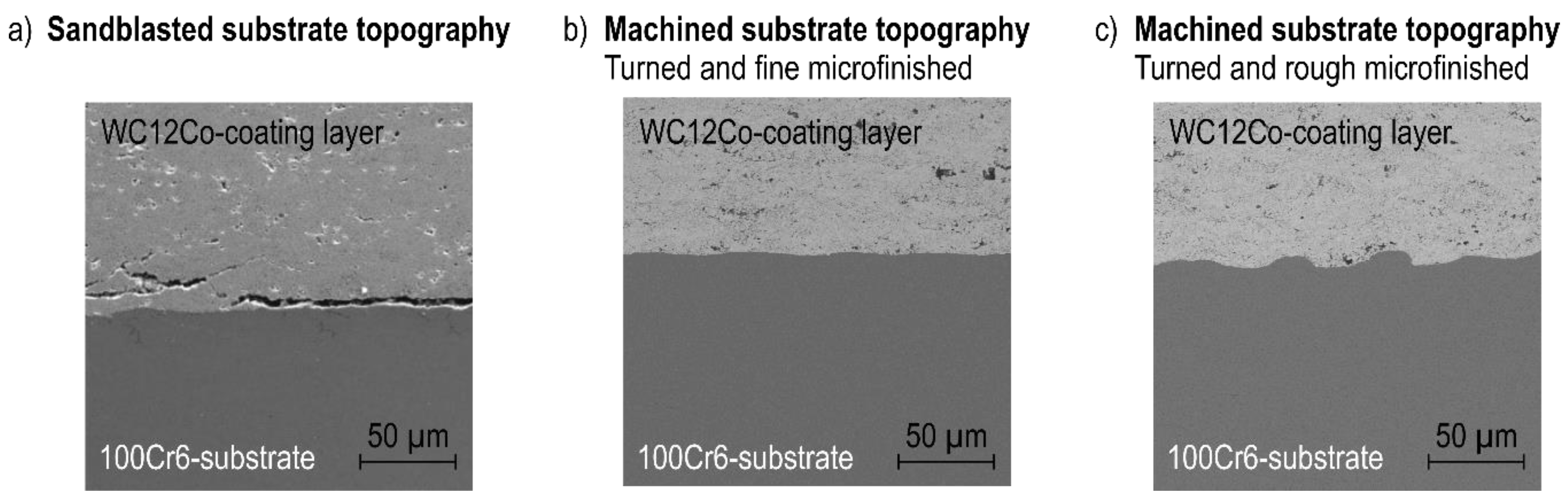
The machined workpieces with the described topographies of the fine and the rough microfinishing strategy were coated by HVOF spraying at the Institute of Materials Engineering. WC–12Co (Woka 3102) was used as feedstock material. To analyze the effect of the machined surface pattern on the obtained coating adhesion, a sandblasted workpiece was used for comparison. The reason for this is largely due to the fact that sandblasting is the most widely used and well-established surface roughening technique in thermal spraying.
Figure 13 shows the cross section SEM picture of the coating–substrate interface, which can be used for qualitative analysis of the coating’s interface.
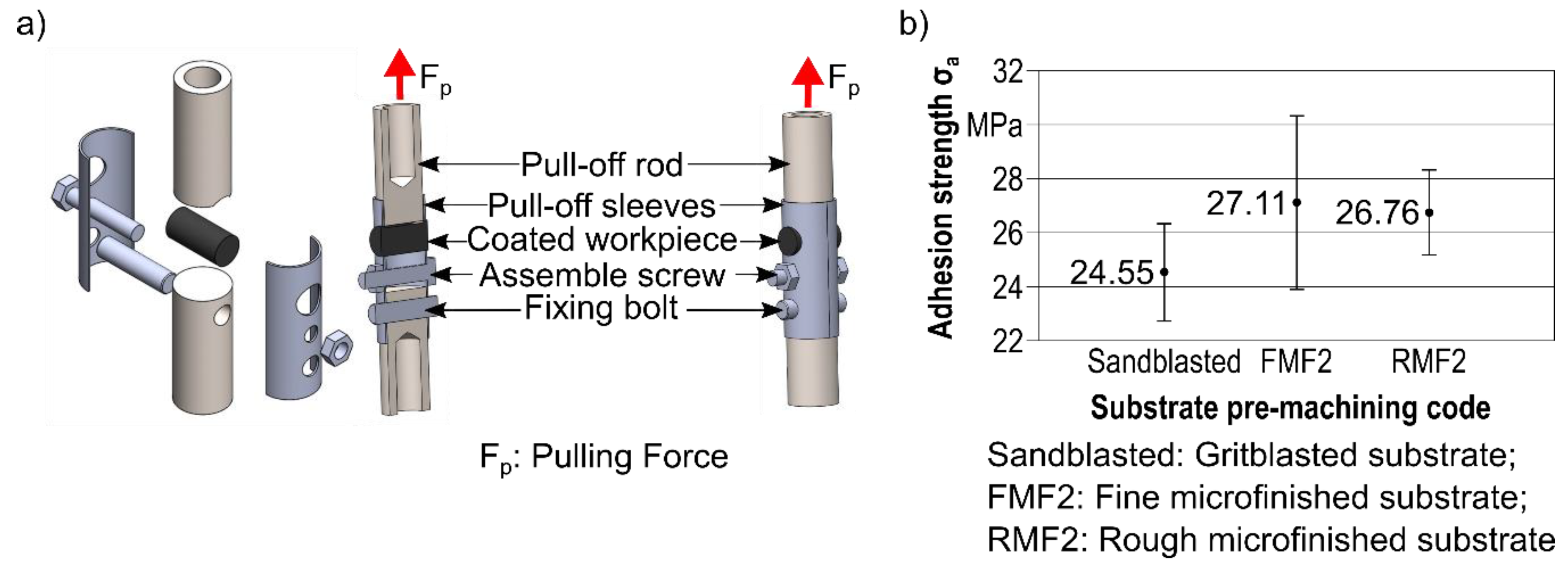
Even though the SEM pictures depict a clear spalling in the case of sandblasting, it does not mean that the coating interface is insufficient or worse than using microfinishing. The institute of material technologies has developed an adhesion testing procedure to test the coating adhesion by cylindrical parts, as shown in
Figure 14. Here, a pull-off rod is glued to a part of the sample circumference of the workpiece using glue. The workpiece is held within a pull-off sleeve. When the pull-off rod is used within a tensile testing machine, it is pulled upwards with increasing pulling force
Fp until it tears off from the workpiece. The forces on the loaded surface are measured so that an adhesion strength can be determined.
For each of these substrate pretreatment strategies, five adhesion tests were performed to calculate an arithmetic mean and display a minimum and maximum value for the adhesion strength. In summary, each sample has a higher adhesion strength than σa = 22 MPa. In the case of the examined workpieces, there was no separation of the coating from the substrate or the layer itself, as the adhesion of the glue had failed before. It can therefore be stated that the procedure is not well established and needs further improvement. The next study will be about the dynamic behavior of all three coated conditions.
4. Discussion
The experimental investigations have shown that it is possible to generate different topographies with microfinishing based on the same initial surface. The patterned topography produced here can enlarge the field of application for microfinishing processes, especially if they prove to be effective for coating adhesion and improve the flexural strength. It has been shown that microfinishing itself can be used for pretreatment, as the adhesive strength does not appear to be lower than that of a sandblasted workpiece. Since microfinishing has high process reliability and repeatability and produces a homogeneous surface topography, it is preferable to sandblasting for the pretreatment of the substrate surface.
Regarding fine microfinishing, the second process step could be shortened to generate a higher Rvk/Rpk ratio. Due to the process kinematics and the material removal mechanisms in microfinishing, the topography is successively almost removed from the surface and not, as in other processes, completely removed with a certain cutting depth. This is due to the fact that the small grain sizes are accompanied by low grain penetration, which can be in the sub micrometer range. Thus, the removal of the initial surface therefore correlates with the process time. A shorter process time leads to less ablation of the material and a greater difference between the resulting heights and depths in the surface. This can further increase the Rvk/Rpk ratio. However, if the Abbott curve is too steep and the Rpk value is too high, it is not possible to enlarge the Rvk/Rpk ratio within the same process time. It must therefore be ensured that the peaks are removed or levelled and that deep grooves remain at the same time. In contrast, a longer microfinishing process can result in the removal of the existing grooves of the original surface structure. This leads to a reduction in both the Rpk and the Rvk values, which means that the Rvk/Rpk ratio does not increase.
As it is already known, the initial surface has a main influence on the resulting surface while microfinishing. Due to the investigations, it was shown that it is possible to use a periodic surface pattern, such as a turning topography, to realize different types of surface pattern by means of microfinishing. The strongest influence on the resulting topography within these investigations is the tool used and the process time. The tool determines the material removal by the grain size and orientation, and the resulting groove depth by the possible grain penetration depth. The process time, in turn, is the decisive control variable for the resulting surface topography, since continuous material removal takes place due to the constant belt feed. With a low material removal rate, the material removal rate can be adjusted to a high material removal rate by increasing the process time.
The residual stress measurement showed that microfinishing in the case of a force-controlled machining process, with its area contact between tool and workpiece, causes compressive residual stresses. Due to the fact that there was no difference between the first and the second fine microfinishing step, it could be helpful also to analyze the residual stress curve. A larger workpiece diameter is needed to enable the use of the borehole method for measuring the residual stresses. Also, one-factor tests regarding the parameters’ surface pressure, cutting velocity, number of overruns, and respective process time, could be suitable to analyze their main influences on the residual stresses during microfinishing.
The results show that a two-dimensional view of technical surfaces can be insufficient and that, in addition to the typical roughness, other parameters should be used for the evaluation. Especially when looking at functional surfaces, a qualitative view can also be useful as it provides an extended impression. For example, the cavities of the rough microfinished surfaces in
Figure 12 appear to be less steep than in the complete profile diagrams of
Figure 3,
Figure 7 and
Figure 8. This can be traced back to the scaling effects, which lead to a distortion or, more precisely, compression of the actual surface. Under standardized observation, it is difficult to speak of grooves and peaks as is usually done.
Regarding the overall aim, it could be determined that the machining strategy of a combination of turning and microfinishing was useful to create homogeneous patterned topographies with outstanding reproducibility that eliminates the adhesion defects and improves the coating interface, independent from the microfinishing strategies. Further investigations have to be made to quantify the coating’s adhesive bonding and the fatigue strength of the workpieces. In the case of rotationally symmetrical workpieces, there is no standardized measurement method for the coating’s adhesive bonding, thus the standard only uses flat-shaped surfaces. Therefore, analogy tests were developed to measure the coating adhesion for the present workpiece geometry. However, no statements could be made about the influence of substrate pretreatment on the coating’s adhesion, as the adhesion of the glue failed for all samples and the coating was not separated from the substrate.
Further research will consist of proving the suitability of these topographies for HVOF coating with a focus on verifying the advantages of the multilayer for functional properties. Therefore, additional rotating bending fatigue tests will be carried out in order to test the fatigue strength of multilayer workpieces with their different substrate surfaces. For this purpose, the coated surface will be microfinished also, to generate a smoothed surface in reference to tribological loaded components.


