Article

Comparative Assessment of the Surface Integrity of AD730® and IN718 Superalloys in High-Speed Turning with a CBN Tool

1
Division of Production and Materials Engineering, Lund University, SE221 00 Lund, Sweden
2
Division of Engineering Materials, Linkoping University, SE58183 Linkoping, Sweden
3
Siemens Industrial Turbomachinery AB, SE61283 Finspang, Sweden
4
R&D Material and Technology Development, Seco Tools AB, SE73782 Fagersta, Sweden
*
Author to whom correspondence should be addressed.
J. Manuf. Mater. Process. 2019, 3(3), 73; https://doi.org/10.3390/jmmp3030073
Submission received: 6 June 2019 / Revised: 8 August 2019 / Accepted: 12 August 2019 / Published: 19 August 2019
(This article belongs to the Special Issue Surface Integrity in Machining)

Abstract

:
Nickel-based superalloys are typical materials used in components of aeroengines and gas turbine machinery. The strength properties of these alloys at high temperatures are crucial not only to the performance (e.g., power generation efficiency, energy consumption, and greenhouse gas emissions) of aeroengines and industrial gas turbines, but also to machinability during component manufacturing. This study comparatively evaluated the surface integrity of two superalloys, AD730® and Inconel 718 (IN718), during high-speed finishing turning using cubic boron nitride (CBN) tools. IN718 is a conventional superalloy used for the hot section components of aeroengines and industrial gas turbines, while AD730® is a novel superalloy with enhanced high-temperature mechanical properties and good potential as a next-generation superalloy for these components. High-speed turning tests of two superalloys were conducted using a CBN cutting tool and jet stream cooling. The achieved surface integrity of the AD730® and IN718 superalloys was characterized and analyzed to assess the comparability of these alloys.

1. Introduction

Nickel-based alloys are widely used in aeroengine and gas turbine components, particularly in those exposed to high temperatures, such as turbine discs and fasteners. These components are often crucial to aeroengine and gas turbine machinery due to their extreme operating conditions, which are characterized by severe mechanical and thermal loads [1]. When manufacturing these components, rigorous and complex quality criteria, encompassing surface and subsurface quality, must be met for safety reasons. In recent decades, Inconel 718 (IN718), a typical nicked-based superalloy, has been used as the major material for turbine discs due to its high temperature and oxidation resistance under operating temperatures in the range of 500~600 °C. This material is currently challenged by increased demands for energy efficiency and low emissions due to its limited maximum service temperature. Recently, a novel nickel-based superalloy, AD730®, was developed by Aubert and Duval [2,3] for higher service temperatures (650~750 °C). This alloy can permit higher operating temperatures in aeroengines and gas turbines, thereby increasing energy efficiency and lowering emissions. What is also important is that the new superalloy has displayed good manufacturability using the conventional cast/wrought route [4] in forming processes. However, as a finishing machining is the process used to obtain the final shape and surface quality during production, it is critical to assess the surface integrity of the alloy after machining and to understand how the obtained surface integrity could affect the fatigue life of the component if this alloy is to be further used. This paper accordingly characterizes and analyzes the surface integrity obtained in the AD730® and IN718 alloys under the same machining conditions to assess the comparability of these superalloys. Scanning electron microscopy (SEM), electron backscatter diffraction (EBSD), and X-ray diffraction were employed in characterizing the surface integrity of these alloys.

2. Surface Integrity of Nickel-Based Superalloys after Machining

Surface integrity is generally characterized by surface topography, mechanical properties, and metallurgical features. Nickel-based superalloys are well known as difficult-to-machine materials due to their high-temperature strength, rapid strain hardening, and low thermal conductivity and the presence of abrasive precipitates in the microstructure [5]. Severe metallurgical, topological, and mechanical alterations induced during machining have been reported in previous investigations [6,7,8,9,10], and these alterations in surface and subsurface regions can degrade the performance and shorten the fatigue life of machined components [8].
Metallurgical alterations include phase transformation as well as recrystallization on the surface and subsurface of the material, causing microstructure change. The formation of a white layer in the surface and near-surface regions is a typical metallurgical alteration induced by machining [9,10,11,12,13]. Characterizing the microstructure using transmission electron microscopy (TEM) on a high-speed-milled surface of the IN100 alloy, Wusatowska et al. [14] reported that the white surface layer comprised a large number of nanograins and that no apparent phase transformation occurred during the formation of the layer. Bushlya et al. [15] also reported white layer generation during the high-speed turning of aged Inconel 718, and grain refinement was found within the white layer, suggesting that this may be attributable to dynamic recrystallization and grain subdivision due to severe plastic deformation (SPD) assisted by high temperature. Using TEM, Chen et al. [16] observed that the white layer generated during the broaching process consisted of nanosized grains, mostly in the 20–50-nm range. Furthermore, regarding the crystallographic texture, transmission Kikuchi diffraction (TKD) revealed that the refined microstructure was primarily caused by strong shear deformation. In another study, Österle and Li [17] observed the dissolution of the γ″ phase in the nanocrystalline structure of the white layer in the superficial layer, suggesting that high temperature may play an important role in microstructure alteration. In machining nickel-based superalloys, a white layer and nanocrystal structures are generated not only during high-cutting-speed processes, such as high-speed turning, but also during low-cutting-speed processes, such as broaching [16] and drilling [18]. The formation mechanism and structure of the white layer are still not clearly understood, though temperature and SPD occurring in the cutting zone are recognized as the main factors contributing to white layer formation on machined components.
Topological alteration covers changes in macro- and microsurface morphological features. Macromorphological features include roughness, waviness, and lay, and micromorphological features include cavities, cracks, smearing, and plucking. In machining superalloys, the factors affecting surface roughness include built-up edge formation and plastic side-flow formation. Pawade et al. [11] found that the surface roughness value was associated with the formation of metal debris adhesion, smeared material, side flow, and feed marks during the high-speed machining of Inconel 718. Sadat [19] reported that surface damage was induced during the machining of IN718 with tungsten carbide (WC) cutting tools, further characterizing the surface damage as comprising cavities, short and long grooves, microcracks, and fractured areas. Devillez et al. [12] and Sharman et al. [20] pointed out that built-up edge formation was the main mechanism causing surface roughness and surface damage formation. In addition, the formation of built-up edges and chip debris is considerably greater under dry-cut conditions and when tool wear is greater. Cutting in the presence of a coolant generally results in less surface damage than does cutting under dry conditions [21]. Ezugwu et al. [22] revealed that machined surface damage of the nickel-based alloy NiCr20TiAl is involved in surface plucking, deformed grains, cavities, and slip zones, and the authors suggested that the plucking and deformed grains are attributable to the plastic flow of the machined surface region during machining.
Mechanical modifications consist of hardness changes, plastic deformation, and residual stresses. Using controlled- and natural-contact-length tools under different cutting conditions, Sadat et al. [23] studied the plastic strain and microhardness distribution in IN718 in machined surfaces under different cutting conditions. In their study, the maximum plastic strain value was found near the surface, and it decreased with increasing depth beneath the machined surface. Sadat et al. found that increasing the cutting speed increased the maximum plastic strain and residual stress due to the increased shear angle and decreased cutting forces in this condition. Sharman et al. [24] measured residual stress as tensile stress at the surface in both TiCN/Al2O3/TiN-coated and uncoated fresh WC tools when turning IN718. Both new and worn uncoated WC tools produced less tensile residual stress than did the coated tools. In addition, the authors also found that higher tensile stresses were measured in the sample when coated rather than uncoated tools were used in the operation due to the greater heat input into the sample surface by the coated tools. On the other hand, they also noted that as the cutting speed increased, the surface residual stress dropped. This result seems contradictory to the results generated with coated tools, since a higher cutting speed also induces more heat in the cutting area. The microstructural damage in the subsurface layer caused by turning IN718 was also revealed in this study.

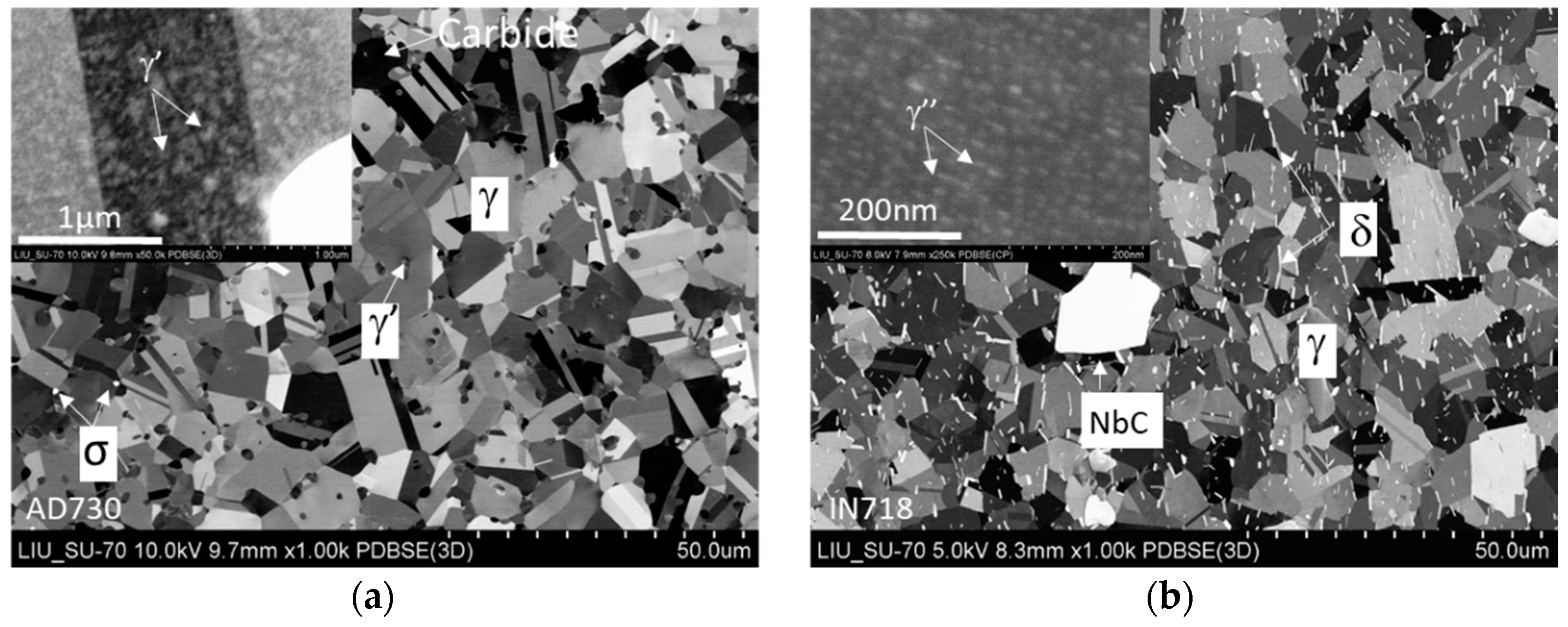
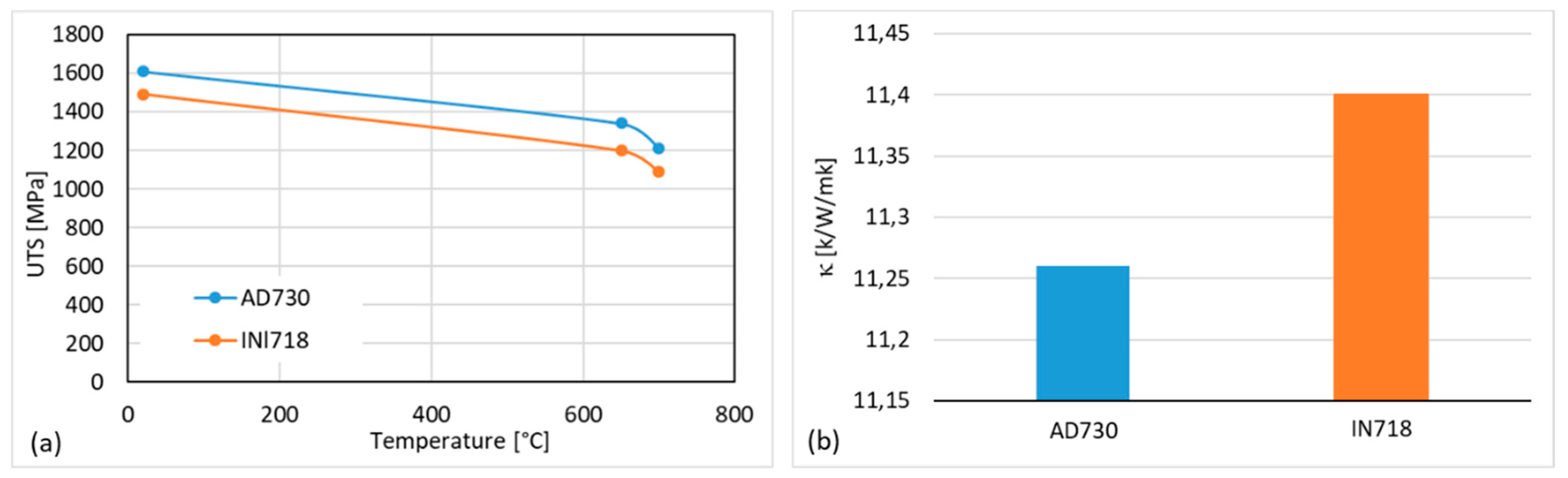
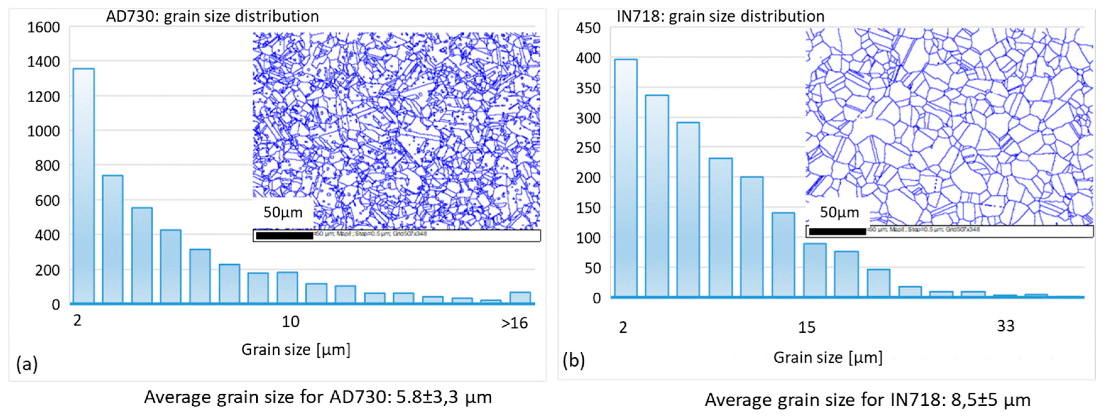
3. AD730® and IN718 Superalloys

The chemical compositions of AD730® and IN718 are presented in Table 1, and the microstructures of the two alloys are compared in Figure 1, which presents micrographs from an SEM backscatter detector. The microstructure of the AD730® alloy consists mainly of two phases, γ as the matrix phase and γ′, a high-volume fraction, as the main strengthening precipitates (see Figure 1a). The γ phase is an Ni-based solid solution rich in elements such as aluminum, titanium, and tantalum, while the γ′ phase is an intermetallic phase of Ni3(Al, Ti), also containing tantalum. The AD730® alloy also contains clusters of carbide and γ phase, which improve the rupture strength of the material at elevated temperatures [3]. IN718 also has a γ matrix, though the strengthening precipitates are γ″, an intermetallic phase of Ni3Nb, complemented by a small amount of γ′ (Figure 1b). In addition, the intermetallic δ phase, which is often distributed at the grain boundaries, and carbides are found.
Devaux et al. [3] studied the mechanical properties of AD730®, finding that it had higher yield strength than did IN718 at an elevated temperature (700 °C) (Figure 2a). By conducting various mechanical tests using a billet after long-term aging at 750 °C, these authors further found that this alloy had high microstructural stability.
Compared to IN718, the γ/γ′ microstructure of AD730® displays enhanced thermal stability [25]. In addition, AD730® alloy components can be produced via the conventional cast/wrought route, which offers a combination of low manufacturing cost, high tensile strength, superior fatigue strength, and creep resistance for components able to work at higher operating temperatures than can IN718 components [4]. Figure 2b shows the alloys’ thermal conductivity at room temperature (RT), with AD730® displaying slightly lower thermal conductivity than does IN718, which is possibly associated with its higher volume percentage of Ni.

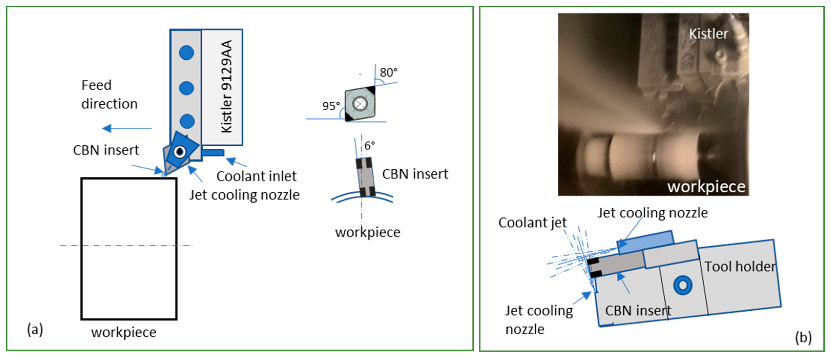
4. Experimental Setup and Procedures

Machining experiments were conducted to generate specimens with machined surfaces under test conditions for the assessment of surface integrity. Polycrystalline cubic boron nitride (PCBN) cutting inserts, comprising CBN 170-grade PCBN brazed on tungsten carbide substrate, were used in the machining tests. CBN 170-grade PCBN is specially designed for machining nickel-based superalloys. This grade consists of 65% CBN content by volume and, as the binding material, TiCN reinforced with SiC whisker fibers, which significantly enhance the fracture toughness. Figure 3a schematically depicts the experimental setup and tool geometry used in the tests. The C-shaped inserts were edge-honed with an edge radius of 25 µm. The inserts were clamped in a tool holder (model PCLNL 3225 P12L; TaeguTec, Daegu, South Korea) providing a cutting geometry with a 95° principal cutting edge angle and a 5° minor cutting edge angle. The tool also has a 6° normal clearance angle together with −6° normal rake and inclination angles. A jet stream coolant device was integrated into the tool holder, as depicting in Figure 3b. The holder could deliver a concentrated high-pressure jet of coolant to the cutting area. The jet stream coolant played two roles in the cutting, making it possible to guide chips in a certain direction away from the cutting zone by optimizing a position near the cutting edge, significantly increasing tool life by improving the cooling efficiency at the cutting edge and improving the surface integrity. Two jet streams were directed onto the rake face and flank face, as shown in Figure 3b. The jet stream coolant was applied throughout the tests. The coolant used in the test was water-based, containing 10% oil emulsion. A computer numerical control (CNC) machine tool (model SMT500) with a maximum spindle speed of 4000 rpm and a drive motor rated at up to 70 kW was used in all machining trials. The test conditions and parameters are presented in Table 2, and the cutting tool specifications are listed as follows:
  • CBN 170-grade PCBN with 65% CBN content by volume and a grain size of ~2 µm;
  • TiCN as a binder reinforced by SiC whisker fibers;
  • High fracture toughness;
  • 25-µm edge radius and edge honing.
The work materials, AD730® and IN718, were received in cylindrical form with a diameter of 70 mm and a length of 300 mm. Before delivery, strengthening heat treatments were applied by the material supplier. For the AD730® alloy, the heat treatment comprised, in sequence, solution annealing at 1080 °C for 4 h, air cooling to 730 °C and aging at that temperature for 8 h, and air cooling to RT. For the IN718 alloy, the heat treatment comprised, in sequence, solution annealing at 970 °C for 4 h and air cooling to RT, then two-stage aging, first at 720 °C for 8 h, and then at 620 °C for another 8 h, followed by air cooling to RT. The nominal bulk hardness was 46 and 45 Hardness Rockwell C (HRC) for AD730® and IN718, respectively. To determine the grain size, EBSD mapping with a step size of 0.5 µm was conducted over a 0.49 × 0.33-mm area. The circular equivalent diameters (CEDs) of grains were then calculated using Channel 5 software. By excluding grains below 2 µm in size, which are usually γ′ particles, the average grain size of γ in CED was found to be 5.8 ± 3.3 µm and 8.5 ± 5 µm for AD730® and IN718, respectively, as shown in Figure 4.
The cutting force (Fc), feed force (Ff), and passive force (Fp) were measured during the experiments using a dynamometer (model 9129AA; Kistler, Winterthur, Switzerland) at a sampling rate of 100 Hz. In the experimental design, the optimal cutting speed and feed rate were selected based on the results of experimental investigation of the wear and life of CBN 170 tools using a wide range of cutting parameters.
After the machining test, specimens were prepared by cross-sectioning and then polishing the machined surface. The microstructures of the machined surface and subsurface layers were characterized using SEM. The plastic deformation and depth of the deformation layer in the surface and subsurface were analyzed and imaged using electron channeling contrast imaging (ECCI) with backscatter detection and electron backscatter diffraction (EBSD). Residual stresses on the machined surfaces in the cutting direction, feed direction (FD), and 45° to the FD were measured using X-ray diffraction.

5. Results and Discussion

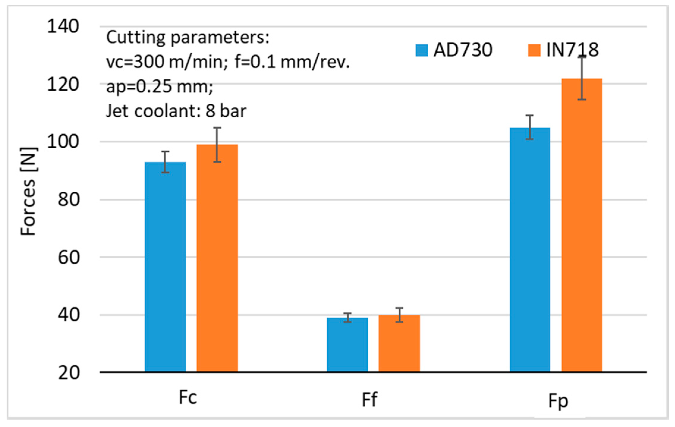
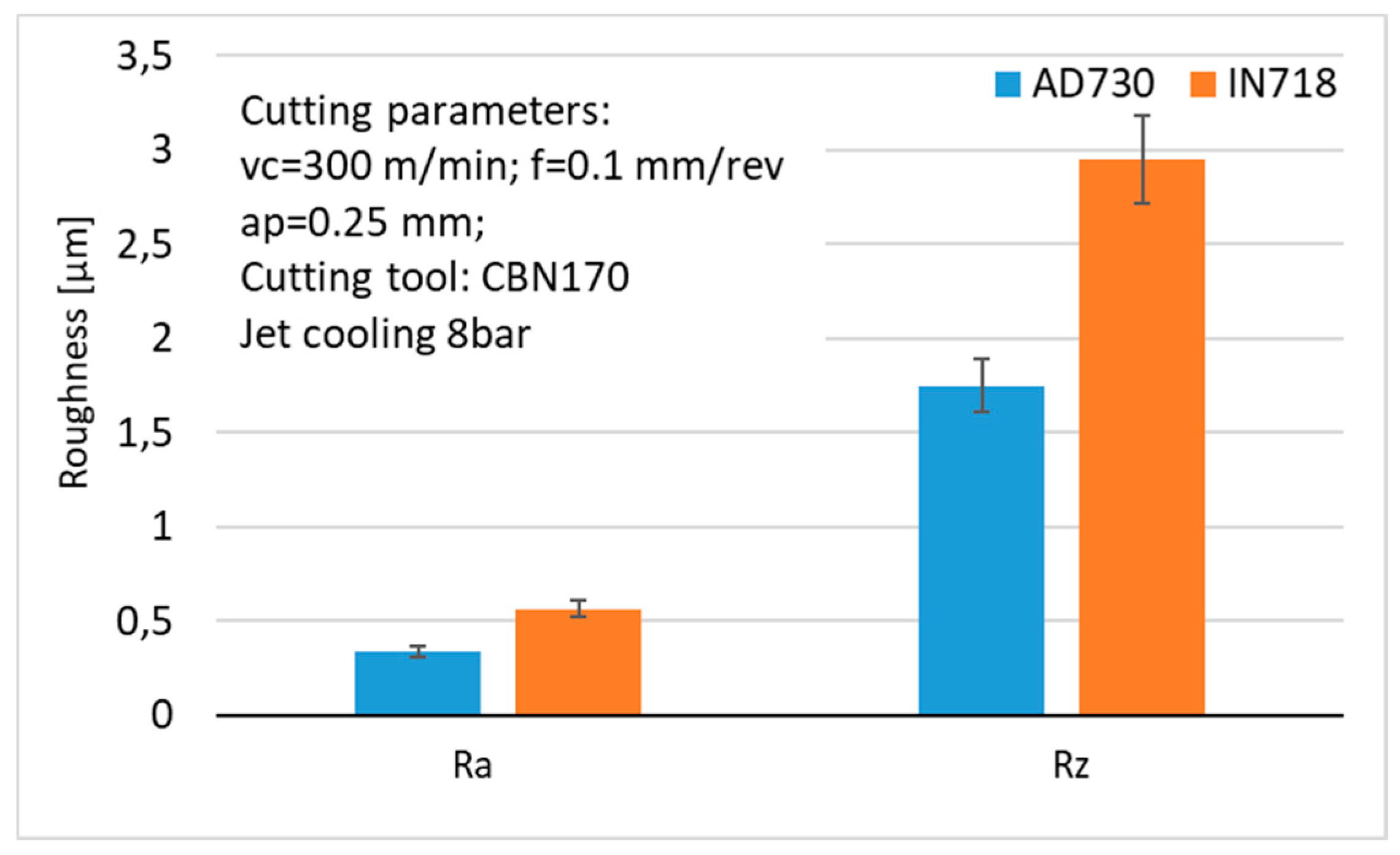
5.1. Cutting Force and Surface Roughness

The three cutting force components measured for the two alloys are presented in Figure 5. The force magnitudes generated when machining AD730® were slightly lower than when machining IN718, although Figure 2a shows that AD730® was stronger than IN718. This may have been attributable to the lower thermal conductivity (γ) of AD730® compared to IN718, as shown in Figure 2b. Lower thermal conductivity in an alloy causes higher cutting temperatures in the shear zone, leading to lower cutting forces.
Figure 6 shows the average surface roughness, Ra, and mean roughness depth, Rz, generated at selected cutting speeds and feed rates. The overall roughness values, Ra and Rz, of the machined surfaces were found to be higher for IN718 than for AD730® under the given machining conditions. The effects of the cutting temperature could have been one reason for the different surface finishes. A microscopic study revealed severe plastic deformation of the surface layer of the machined AD730® alloy as a result of the higher cutting temperature (Figure 7c). This plastic deformation filled the valleys on the surface, leading to better surface roughness values. Another factor could be the formation of burrs or side flow between the tool and the workpiece due to the higher temperature, which may have changed the height of the surface: this effect was also observed by Ezugwu and Tang [10].

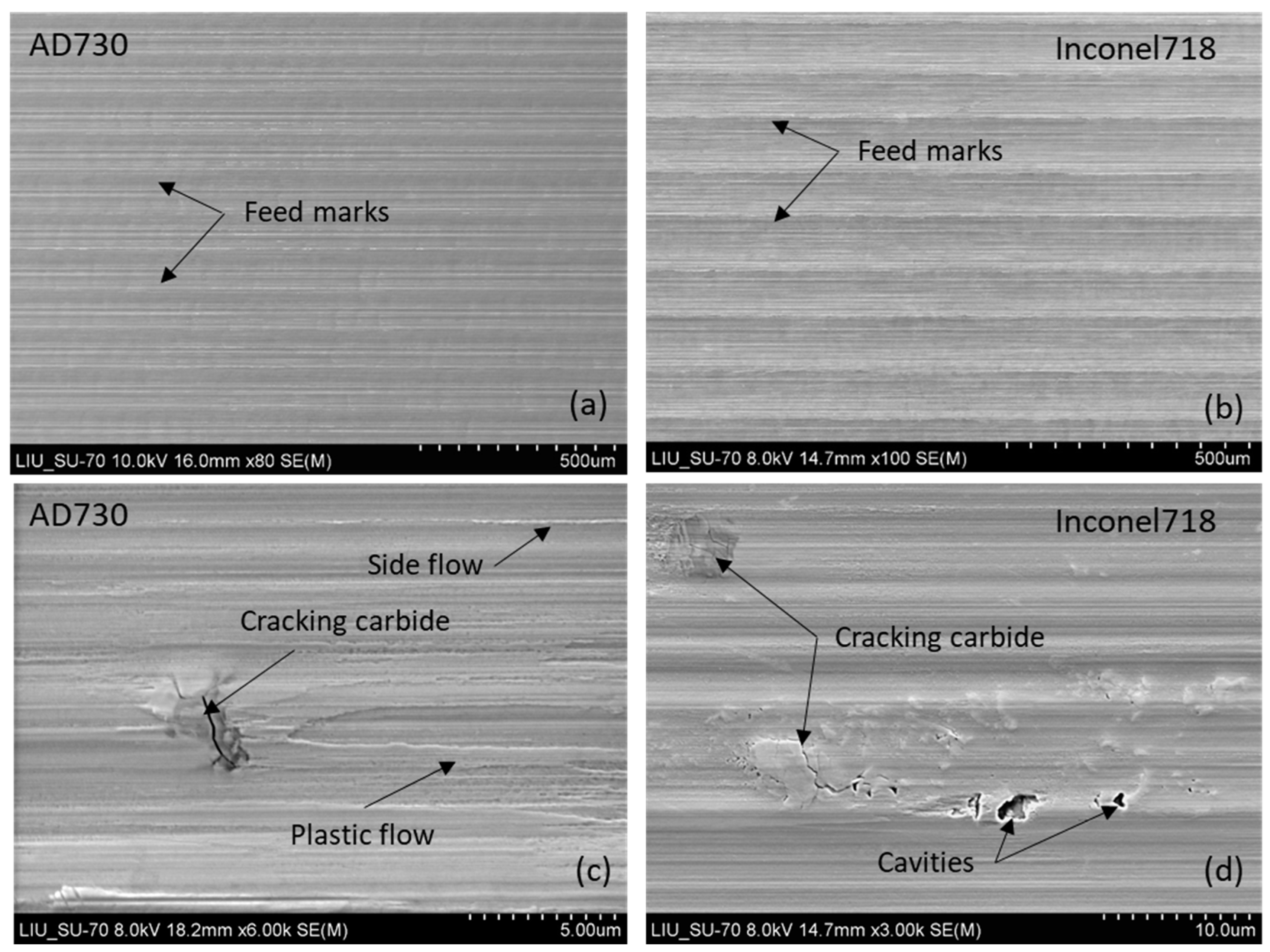
5.2. Surface Morphology

Using SEM, surface morphology and possible surface damage induced during the machining were investigated in specimens cut from the machined parts. SEM images of the surface morphology of AD730® and IN718 parts after machining using CBN tools are shown in Figure 7. Machined surfaces of both AD730® and IN718 contained many surface defects of various types. Quantitative analysis did not provide that much information about the different behaviors of the two alloys during high-speed machining. Instead, the observations indicated different dominant surface defects on machined AD730® and IN718 under the same cutting conditions, with more plastic flow and side flow being observed on machined AD730®, as shown in Figure 7c,d, indicating that higher cutting temperatures could be expected during the machining. On the other hand, the carbide cracking on machined IN718 was of greater concern regarding fatigue properties, considering the much larger cracks compared to those on machined AD730®.
Several types of surface defects were observed, including side flow in the cutting direction, surface smearing, carbide cracking under the cutting forces, and plastic flow caused by high temperatures. It is unclear which of the specimens had the most defects, since no quantitative studies of top-surface defects were performed in this study. Although it is difficult to rank the different defects in terms of severity and intensity, of the observed defects, side flow, smearing, and carbide cracking were present along with plastic deformation in almost all samples. Plastic flow seemed significantly affected by the cutting speed, since it was observed only in the sample produced at the highest cutting speed, in which a higher cutting temperature was induced. Other authors [13,14] have previously observed similar types of defects in the high-speed machining of other types of nickel-based superalloys. It is known that all types of surface defects can cause stress concentration, which is detrimental to the strength properties, fatigue, and lifetime of components.

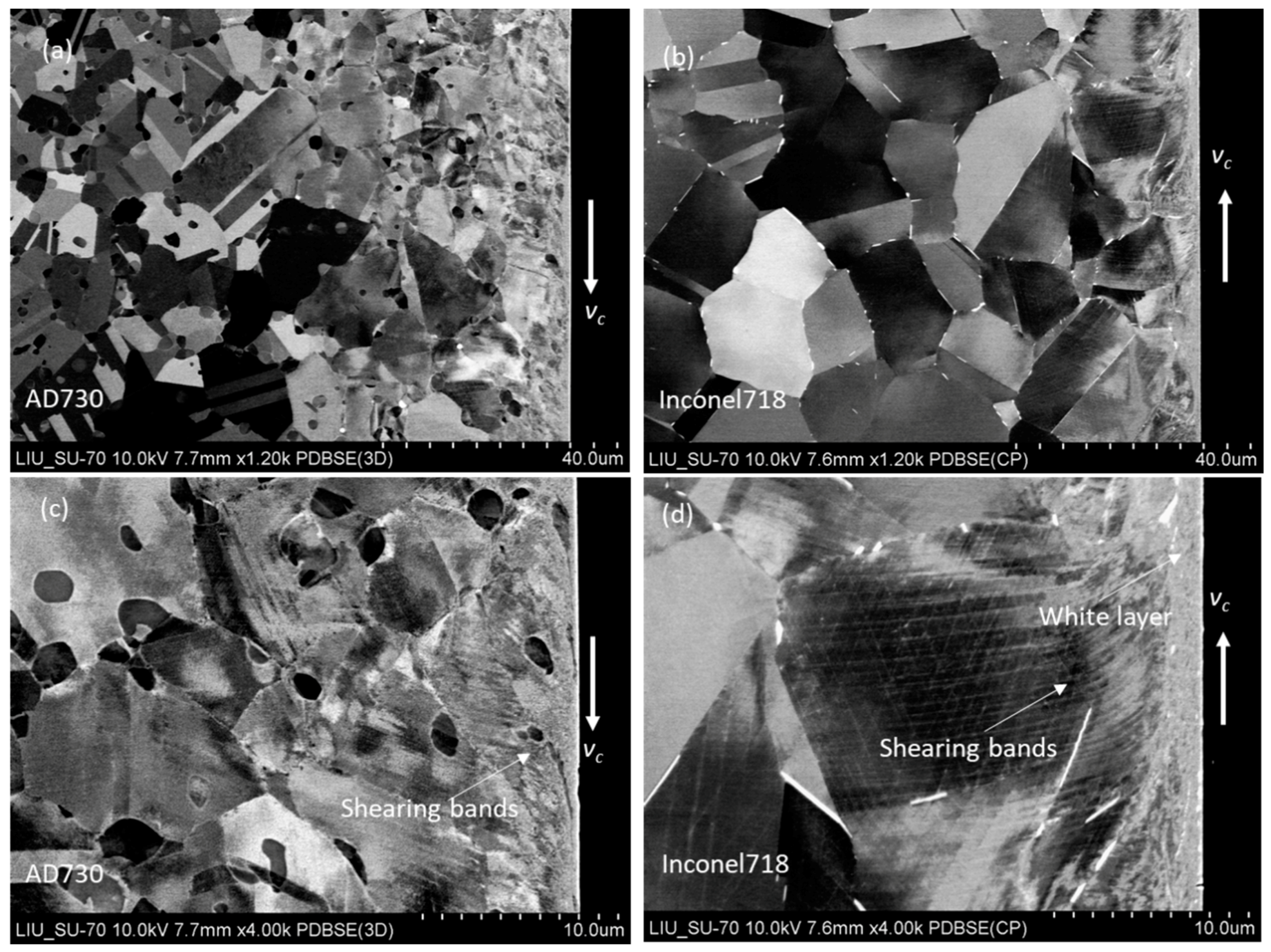
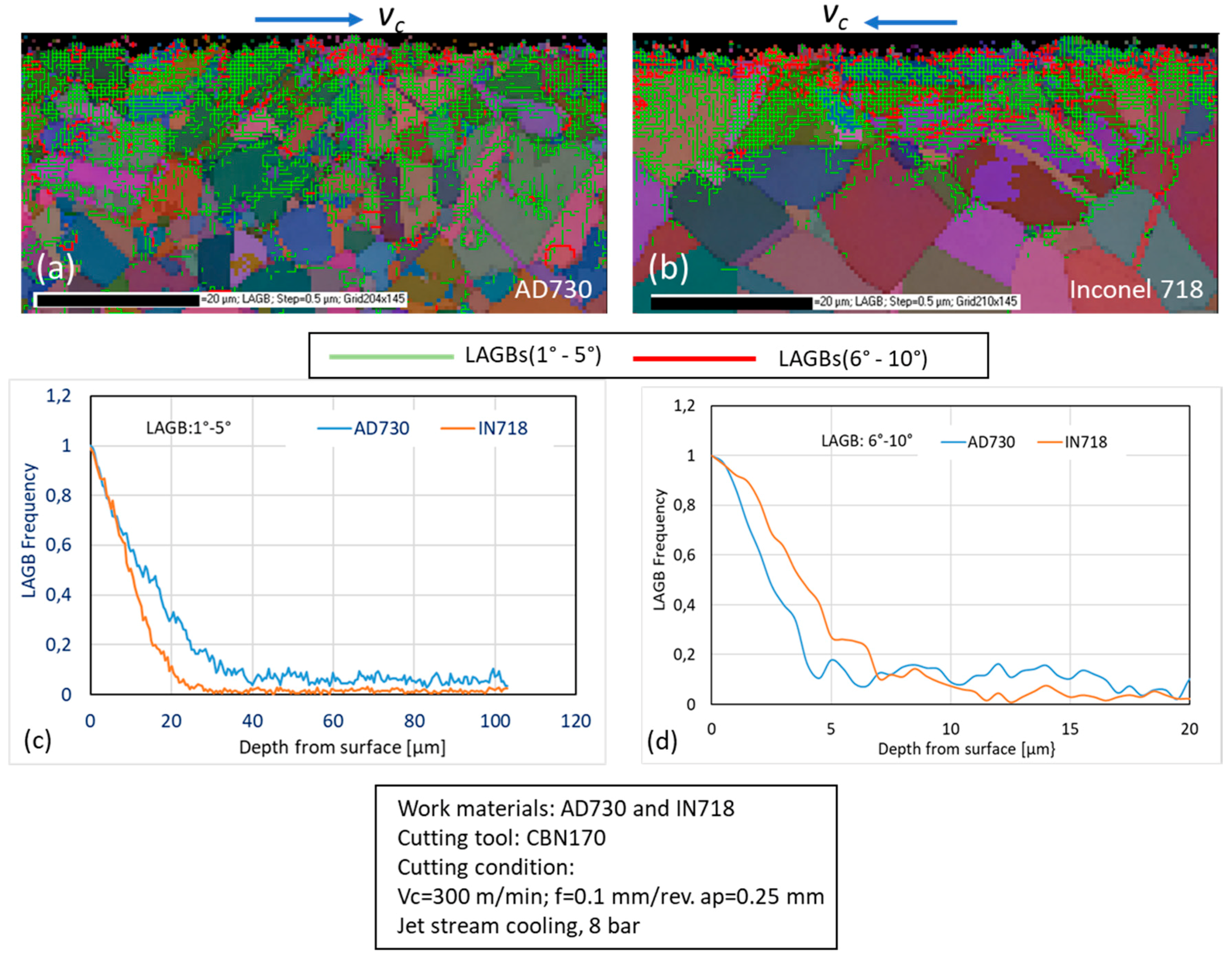
5.3. Subsurface Deformation

Plastic deformation caused by thermomechanical loading during the machining process was clearly observed in the machined surfaces and subsurfaces of the specimens. Figure 8 shows the subsurface deformation of specimens of two alloys observed in backscatter mode. The slip bands and shearing bands shown in Figure 8 indicate substantial plastic deformation induced by the cutting process when these materials were machined. The severe subsurface deformation of the shallow subsurface layer was primarily affected by the thermal load relating to the friction between the workpiece and cutting tool, while the overall depth of the plastic deformation of the subsurface was associated with the mechanical load, which related to the thickness of the material removed during the machining. Under these machining conditions, the two alloys differed substantially in white layer formation on the machined surface. As shown in Figure 8c,d, in the IN718 alloy, the machined surface was covered by a continuous white layer 1~2 µm thick. In the AD730® alloy under the same machining conditions, although severe shear deformation occurred in a surface layer 0.5~1 µm thick, as shown by the greatly elongated γ′ particles, there was no clear evidence of white layer formation. This could be because of the lower thermal stability of the γ″ phase in IN718, while there was no γ″ phase in AD730®, resulting in different deformation behavior in the surface layers during machining. The conditions for white layer formation are complicated, but severe plastic deformation (SPD) plays a key role in the process. In IN718 at a cutting speed of 300 m min−1, the cutting temperature can exceed 1100 °C [28] in the cutting area. The γ″ phase can dissolve at such a high temperature, and the resulting local softening can facilitate considerable plastic deformation, contributing to white layer formation on the machined surface. Many investigations have found that the white layer structure consists of nanograins from microstructure refining occurring on the surface to accommodate the SPD induced by the large localized shear induced by machining [13].
The extent of subsurface plastic deformation can be qualitatively visualized using the EBSD technique, in which the strain orientations are calculated and the strain contours are mapped within each grain [29]. In this work, to evaluate and compare the depth of machining-induced plastic deformation in both alloys, EBSD orientation maps of the machining-affected depth (see, e.g., Figure 9a,b) were obtained, from which the frequency of low-angle grain boundaries (LAGBs) was calculated (Figure 9c). In Figure 9a,b, LAGBs of 1–5° (light deformation) in the deformation area are represented by green lines, while LAGBs of 6–10° (severe deformation) are represented by red lines. Five orientation maps for each alloy were used to calculate the depth profiles of LAGB concentrations, shown in Figure 9c,d. Figure 9 shows a high concentration of low-angle grain boundaries, which decreased with increasing distance from the machined surface. In both alloys, the intensity of subsurface deformation was approximately the same at depths under 10 µm, at which the LAGB frequency exceeded 60%, as shown in Figure 9c. The LAGB frequency decreased to almost zero when the depth from the surface reached 30 µm for IN718. Meanwhile, the LAGB frequency reached a stable value at a depth of 40 µm in AD730®, suggesting that the machining induced a greater plastic deformation depth in AD730® than in IN718 under the same cutting conditions. However, IN718 displayed a higher intensity of SPD in the yellow surface region than did AD730®, as shown in Figure 9d. The overall intensity of LAGBs was higher for AD730® than for IN718, which may have been associated with the influence of cutting temperature as well as the grain size of the alloys.

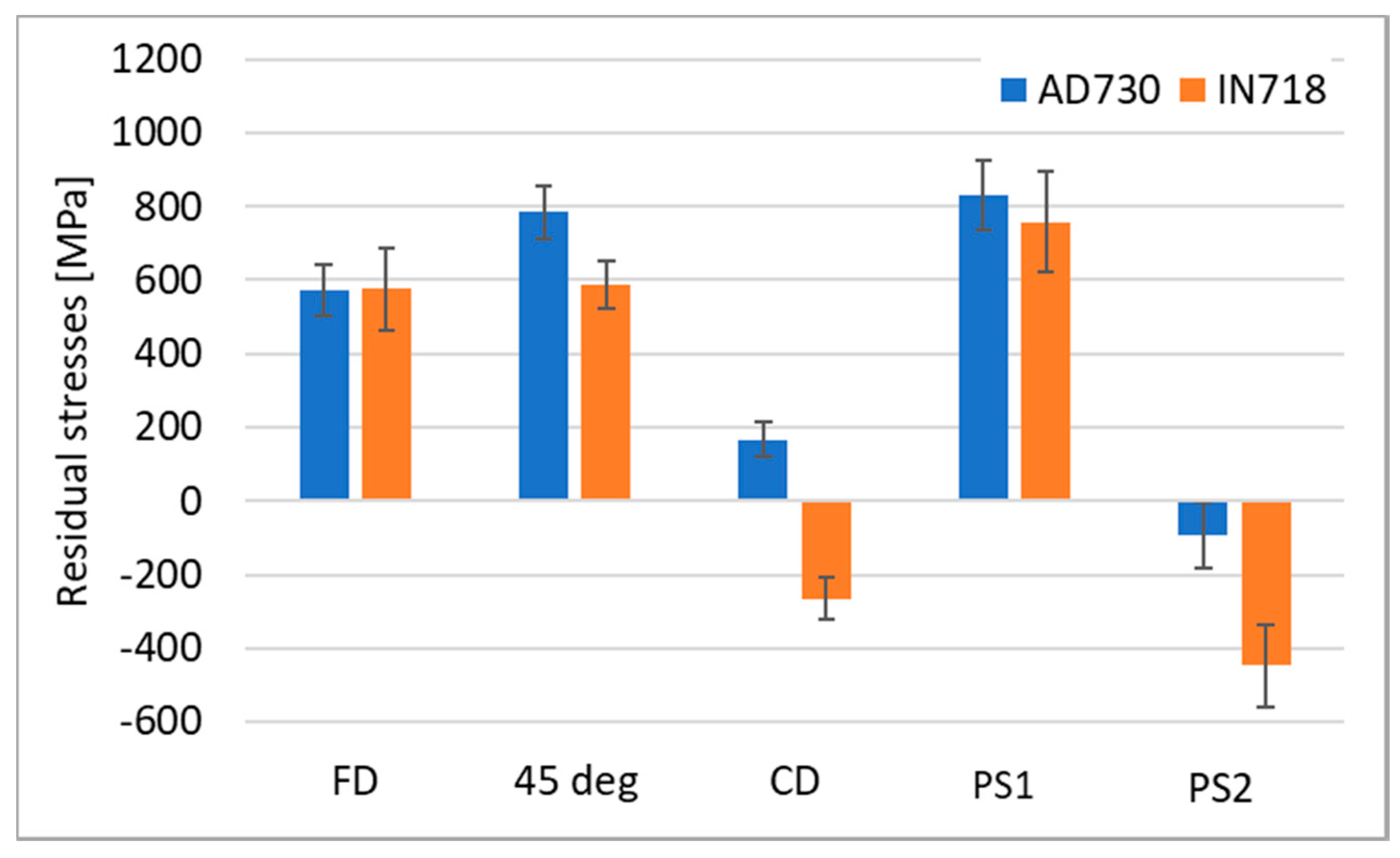
5.4. Residual Stresses

Residual stresses induced by machining processes in the machined parts, depending on their magnitudes and signs, can be very detrimental to the service life or fatigue life of machined components [18]. Often it is difficult to predict the residual stresses generated during machining due to the complex load scenario in a machining process. Mechanical and thermal loads always occur simultaneously when machining a component, and the partition of each load is often unknown. The heat generated in the cutting zone causes compressive deformation of the surface layer as the thermal expansion is constrained by the underlying materials. The thermally induced residual stresses therefore always develop in tension. However, mechanically induced residual stresses could be either compressive or tensile, depending on the relative dominance of the compressive plastic deformation ahead of the cutting tool tip and the tensile plastic deformation behind it, which arises from the rubbing of the tool flank face [30,31]. Therefore, the type of mechanical deformation that dominates during machining in the cutting direction (CD) and feed direction (FD) is important to the final residual stress state in a specific case.
The residual stresses on the machined surfaces were measured in the CD, FD, and 45° to the FD by X-ray diffraction. Each residual stress measurement involved measurements of diffraction peaks at nine ψ tilts from +55° to −55°. Assuming a plane stress state, the residual stress was calculated based on the “sin2 ψ” method using an X-ray elastic constant of 4.65 × 10⁻⁶ MPa−1 (according to Kitagawa et al. [29]) for IN718 and 5.22 × 10⁻⁶ MPa−1 (from a calibration measurement) for AD730®.
Figure 10 presents a summary of the surface residual stresses generated in the high-speed machining of two alloys with a CBN tool under jet stream cooling conditions. In addition to the measured stresses, the in-plane principal stresses (i.e., the maximum and minimum normal stresses calculated based on the measured stresses) were also plotted. As can be seen, tensile residual stresses were measured on the machined surfaces of AD730® even though the magnitudes in CD were relatively small. Tensile residual stress was measured in the FD in IN718, while a low magnitude of compressive stress was found in the CD. Furthermore, while the calculated maximum normal stress, PS1, was similar in both alloys, i.e., 831 ± 97 MPa in AD730® and 845 ± 180 MPa in IN718, the minimal normal stress, PS2, was larger in compression in IN718 (−421 ± 149 MPa) than in AD730® (−93 ± 91 MPa). That tensile surface residual stresses were more dominant in AD730® could have been attributable to the higher cutting temperature, as discussed above.

6. Conclusions

The surface integrity of two nickel-based superalloys produced during high-speed turning using a CBN tool under jet stream cooling conditions was comparatively evaluated. Under the same test conditions, the novel superalloy, AD730®, despite having better high-temperature strength than IN718 did, displayed lower magnitudes of cutting force (~10%) than did IN718 due to its lower thermal conductivity. Lower surface roughness was obtained from AD730® after machining as a result of severe plastic deformation that minimized the effect of feed marks. Surface defects were found on the machined surfaces of both alloys, including carbide cracking, plastic flow, and smearing, all of which affected the surface roughness. Severe plastic deformation was discovered in the subsurface layers of both alloys after machining. The depth of plastic deformation was somewhat greater in the subsurface of AD730® than in IN718, which was possibly attributable to the larger grains of IN718. In addition, no obvious white layer was observed on the machined AD730®, while a continuous white layer was found on the machined IN718. Further investigation is needed to understand the mechanism and effects of microstructure formation. Finally, tensile residual stresses were more dominant in the machined surface of AD730® than in IN718.

Author Contributions

Conceptualization, J.Z. and Z.C.; methodology, Z.C. and J.Z; formal analysis, Z.C.; investigation, Z.C. and H.P.; resources, D.G. and R.M.; data curation, Z.C. and H.P.; writing—original draft preparation, J.Z.; writing—review and editing, R.L.P. and J.Z.; visualization, J.Z. and Z.C.; supervision, R.M. and D.G.; project administration, R.L.P.; funding acquisition, R.L.P. and J.Z.

Funding

This research was funded by the Swedish government agency for innovation (VINNOVA), grant number 2016-05449.

Acknowledgments

The authors would also like to thank Siemens Industrial Turbomachinery AB and SECO Tools AB for the assistance during the experiment.

Conflicts of Interest

The authors declare no conflict of interest.

References

  1. Klocke, F.; Gierlings, S.; Brockmann, M.; Veselovac, D. Influence of Temperature on Surface Integrity for Typical Machining Processes in Aero Engine Manufacture. Procedia Eng. 2011, 19, 203–208. [Google Scholar] [CrossRef] [Green Version]
  2. Devaux, A.; Geoges, E.; Héritier, P. Development of new C&W superalloys for high temperature disk applications. Adv. Mater. Res. 2011, 278, 405–410. [Google Scholar]
  3. Devaux, A.; Picqué, B.; Gervais, M.; Georges, E.; Poulain, T.; Heritier, P. AD730—A New Nickel-Based Superalloy for High Temperature Engine Rotative Parts. In Superalloys 2012; Wiley-Blackwell: Hoboken, NJ, USA, October 2012; pp. 911–919. [Google Scholar]
  4. Devaux, A.; Berglin, L.; Thebaud, L.; Delattre, R.; Crozer, C.; Nodin, O. Mechanical properties and development of supersolvus heat treated new nickel base superalloy AD730TM. MATEC Web Conf. 2014, 14, 01004. [Google Scholar] [CrossRef]
  5. Thakur, A.; Gangopadhyay, S. State-of-the-art in surface integrity in machining of nickel-based superalloys. Int. J. Mach. Tools Manuf. 2016, 100, 25–54. [Google Scholar] [CrossRef]
  6. Ezugwu, E.O.; Wang, Z.M.; Machado, A.R. The machinability of nickel-based alloys: A review. J. Mater. Process. Technol. 1999, 86, 1–16. [Google Scholar] [CrossRef]
  7. Jawahir, I.S.; Brinksmeier, E.; M’Saoubi, R.; Aspinwall, D.K.; Outeiro, J.C.; Meyer, D.; Umbrello, D.; Jayal, A.D. Surface integrity in material removal processes: Recent advances. CIRP Ann. Manuf. Technol. 2011, 60, 603–626. [Google Scholar] [CrossRef]
  8. Chen, Z.; Lin Peng, R.; Moverare, J.; Avdovic, P.; Zhou, J.M.; Johansson, S. Surface Integrity and Structural Stability of Broached, Inconel 718 at High Temperatures. Metall. Mater. Trans. A 2016, 47, 3664–3676. [Google Scholar] [CrossRef]
  9. Zou, B.; Chen, M.; Huang, C.; An, Q. Study of surface damages caused by turning of NiCr20TiAl nickel-based alloy. J. Mater. Process. Technol. 2009, 209, 5802–5809. [Google Scholar] [CrossRef]
  10. Ezugwu, E.O.; Tang, S.H. Surface abuse when machining cast iron (G-17) and nickel base superalloy (Inconel 718) with ceramic tools. J. Mater. Process. Technol. 1995, 55, 63–69. [Google Scholar] [CrossRef]
  11. Pawade, R.S.; Suhas, S.; Joshi, S.; Brahmankar, P.K.; Rahman, M. An investigation of cutting forces and surface damage in high-speed turning of Inconel 718. J. Mater. Process. Technol. 2007, 192–193, 139–146. [Google Scholar] [CrossRef]
  12. Devillez, A.; Le, G.; Dominiak, S.; Dudzinski, D. Dry machining of Inconel 718, workpiece surface integrity. J. Mater. Process. Technol. 2011, 211, 1590–1598. [Google Scholar] [CrossRef]
  13. Ulutan, D.; Ozel, T. Machining induced surface integrity in titanium and nickel alloys: A review. Int. J. Mach. Tools Manuf. 2011, 51, 250–280. [Google Scholar] [CrossRef]
  14. Wusatowska-Sarnek, A.; Dubiel, B.; Czyrska-Filemonowicz, A.; Bhowal, P.; Salah, N.B.; Klemberg-Sapieha, J. Microstructural characterization of the white etching layer in nickel-based superalloy. Metall. Mater. Trans. A 2011, 42, 3813–3825. [Google Scholar] [CrossRef]
  15. Bushlya, V.; Zhou, J.M.; Lenrick, F.; Avdovic, P.; Ståhl, J.E. Characterization of White Layer Generated when Turning Aged Inconel 718. Procedia Eng. 2011, 19, 60–66. [Google Scholar] [CrossRef] [Green Version]
  16. Chen, Z.; Colliander, M.H.; Sundell, G.; Peng, R.L.; Zhou, J.M.; Johansson, A.; Moverare, J. Nano-scale characterization of white layer in broached Inconel 718. Mater. Sci. Eng. A 2017, 684, 373–384. [Google Scholar] [CrossRef] [Green Version]
  17. Österle, W.; Peng, L.R. Mechanical and thermal response of a nickel-base superalloy upon grinding with high removal rates. Mater. Sci. Eng. A 1997, 238, 357–366. [Google Scholar] [CrossRef]
  18. Imran, M.; Mativenga, P.T.; Gholinia, A.; Withers, P.J. Evaluation of surface integrity in micro drilling process for nickel-based superalloy. Int. J. Adv. Manuf. Technol. 2011, 55, 465–476. [Google Scholar] [CrossRef]
  19. Sadat, A.B. Surface characteristics of machined Inconel-718 nickel-base superalloy using natural and controlled contact length tools. Int. J. Mach. Tool Manuf. 1987, 27, 333–342. [Google Scholar] [CrossRef]
  20. Sharman, A.R.C.; Hughes, J.I. Workpiece surface integrity and tool life issues when turning Inconel 718™ nickel based superalloy. J. Mach. Sci. Technol. 2004, 200, 424–432. [Google Scholar] [CrossRef]
  21. Zhou, J.Z.; Bushlya, V.; Stahl, J.E. An investigation of surface damage in the high speed turning of Inconel 718 with use of whisker reinforced ceramic tools. J. Mater. Process. Technol. 2012, 212, 372–384. [Google Scholar] [CrossRef]
  22. Ezugwu, E.O.; Pashby, I.R. High speed milling of nickel-based superalloys. J. Mater. Process. Technol. 1992, 3, 429–437. [Google Scholar] [CrossRef]
  23. Sadat, A.B.; Reddy, M.; Wang, B.P. Plastic deformation analysis in machining of Inconel 718 nickel-based superalloy using both experimental and numerical methods. Int. J. Mech. Sci. 1991, 33, 829–842. [Google Scholar] [CrossRef]
  24. Sharman, A.R.C.; Hughes, J.I.; Ridgway, K. An analysis of the residual stresses generated in Inconel 718™ when turning. J. Mater. Process. Technol. 2006, 173, 359–367. [Google Scholar] [CrossRef]
  25. Chen, Z.; Peng, R.L.; Zhou, J.M.; M’Saoubi, R.; Gustafsson, D.; Moverare, J. Effect of machining parameters on cutting force and surface integrity when high-speed turning AD 730™ with PCBN tools. Int. J. Adv. Manuf. Technol. 2018. [Google Scholar] [CrossRef]
  26. Aubert & Duval. AD730®—New Ni-based Superalloy for High Temperature Applications; Aubert & Duval: Paris, France, 2012. [Google Scholar] [CrossRef]
  27. Ahn, D.G.; Byun, K.W.; Kang, M.C. Thermal Characteristics in the Cutting of Inconel 718 Superalloy Using CW Nd:YAG Laser. J. Mater. Sci. Technol. 2010, 26, 362–366. [Google Scholar] [CrossRef]
  28. New Seco Jetstream Cooling®. Available online: http://www.secotools.com (accessed on 7 March 2018).
  29. Kitagawa, T.; Kubo, A.; Maekawa, K. Temperature and wear of cutting tools in high-speed machining of Incone1718 and Ti-6A1-6V-2Sn. Wear 1997, 202, 142–148. [Google Scholar] [CrossRef]
  30. M’Saoubi, R.; Axinte, D.; Soo, S.L.; Nobel, C.; Attia, H.; Kappmeyer, G.; Engin, S.; Sim, W.M. High performance cutting of advanced aerospace alloys and composite materials. CIRP Ann. Manuf. Technol. 2015, 64, 557–580. [Google Scholar] [CrossRef]
  31. Zhou, J.M.; Peng, R.L.; M’Saoubi, R.; Gustafsson, D.; Palmert, F.; Moverare, J. Plastic, Deformation and Residual Stress in High Speed Turning of AD730™ Nickel-based Superalloy with PCBN and WC Tools. Procedia CIRP 2018, 71, 440–445. [Google Scholar]
Figure 1. Microstructures of (a) AD730® and (b) IN718.
Jmmp 03 00073 g001
Figure 2. (a) Ultimate tensile strength (UTS) of AD730® and IN718 at different temperatures [2]; (b) thermal conductivity (κ) of AD730® and IN718 at room temperature (RT) [26,27].
Jmmp 03 00073 g002
Figure 3. (a) Experimental setup and (b) tool geometry and jet stream cooling configuration.
Jmmp 03 00073 g003
Figure 4. Electron backscatter diffraction (EBSD) mapping of grain size distribution on received (a) AD730® and (b) IN718.
Jmmp 03 00073 g004
Figure 5. Cutting forces generated by AD730® and IN718 in the turning process.
Jmmp 03 00073 g005
Figure 6. Surface roughness generated by AD730® and IN718.
Jmmp 03 00073 g006
Figure 7. Surface morphology of AD730® and IN718 after machining; (a,b) Overview of machined surface with feed marks; (c,d) surface defects.
Jmmp 03 00073 g007
Figure 8. Subsurface deformation of (a) AD730® and (b) IN718, (c) close-up view of AD730® surface deformation, and (d) indications of white layer formation in IN718.
Jmmp 03 00073 g008
Figure 9. EBSD mapping of the subsurface deformation of (a) AD730® and (b) IN718 and the corresponding intensity level of low-angle grain boundaries (LAGBs) in the range of (c) 1–5° and (d) 6–10°.
Jmmp 03 00073 g009
Figure 10. Surface residual stresses measured in the cutting direction (CD), feed direction (FD), and 45° to the FD as well as the derived principal stresses (PS1 and PS2) for AD730® and IN718.
Jmmp 03 00073 g010
Table 1. Chemical compositions of AD730TM and Inconel 718 (IN718) [2].
Elements (vol. %)AD730©IN718
Ni59.453.8
Fe3.9417.8
Cr15.617.9
Co8.420.17
Mo3.022.92
Al2.320.47
Ti3.511.01
Nb1.125.4
C0.020.025
W2.59-
Zr0.05-
B0.020.004
Si-0.07
Mn-0.06
Cu-0.04
Table 2. Test conditions and parameters. CBN: cubic boron nitride.
Cutting toolPCLNL 3225 P12L
Insert gradeCBN 170
Cutting speed: vc (m·min−1)300
Feed rate: f (mm·rev−1)0.1
Depth of cut: ap (mm)0.25
Cooling pressure (bar)8
Cooling methodJet stream

