In-Situ Fretting Wear Analysis of Electrical Connectors for Real System Applications


Abstract
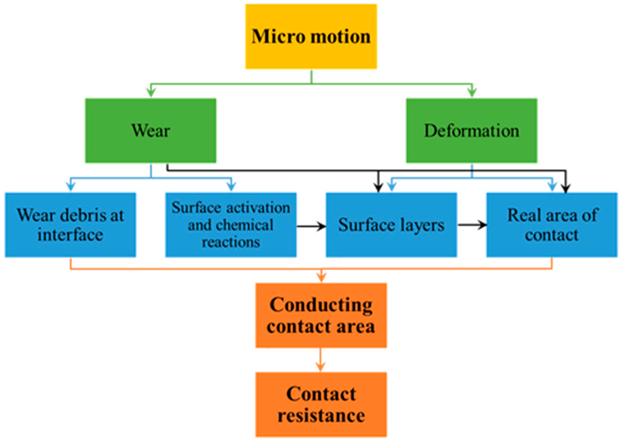
:1. Introduction
2. Materials and Methods
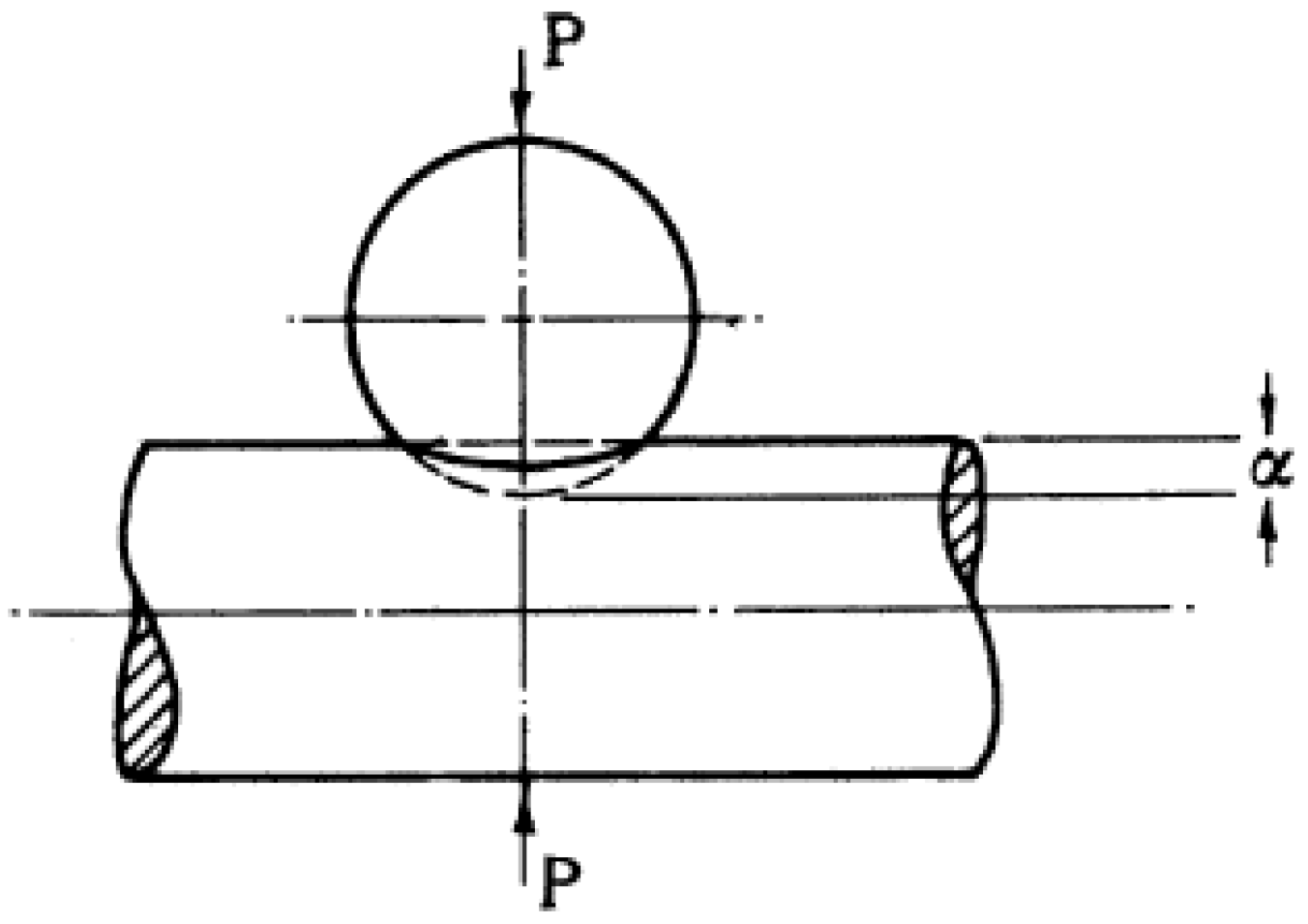
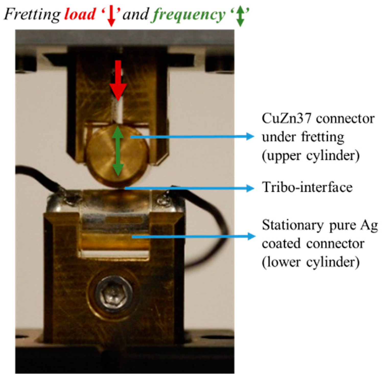
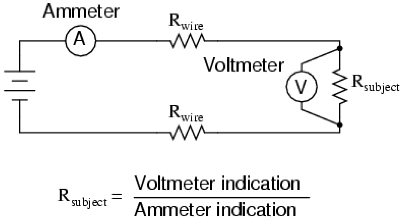
2.1. Contact Conditions and Electrical Resistance Measurement
- α—the total elastic compression at the point or line of contact of two bodies, measured along the line of the applied force
- D—Diameter of both cylindrical bodies = 9 mm
- P—Applied force = normal load variation of 1–5 N
- E—Young’s modulus of material of body
- E1 = Young’s modulus of upper cylinders = 110 Gpa
- E2 = Young’s modulus of lower cylinders = 76 Gpa
- G—Modulus of rigidity of material of the body
- G1 = modulus of rigidity s of upper cylinders = 40 Gpa
- G2 = modulus of rigidity of lower cylinders = 27.8 Gpa
- σ—Poisson’s ratio = E/(2G − 1)
- σ1 = Poisson’s ratio of upper cylinders = 0.3
- σ2 = Poisson’s ratio of lower cylinders = 0.37
- V1 (upper cylinder) = (1 − σ12)/πE1
- V2 (lower cylinder) = (1 − σ22)/πE2
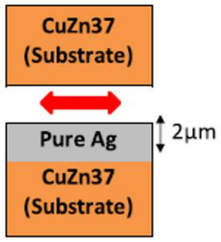
2.2. Materials
3. Results and Discussion
3.1. Effect of Load
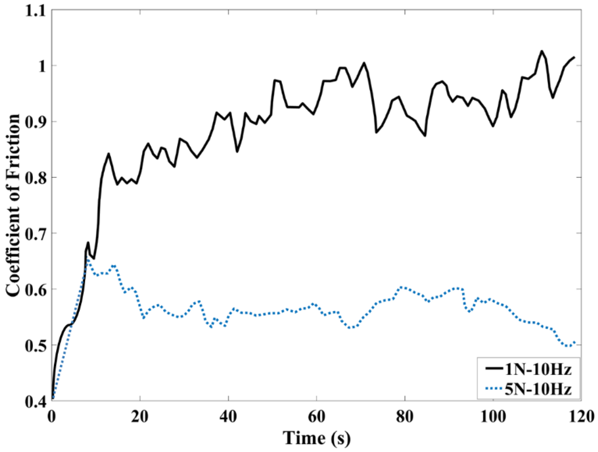
3.1.1. Coefficient of Friction
3.1.2. Wear
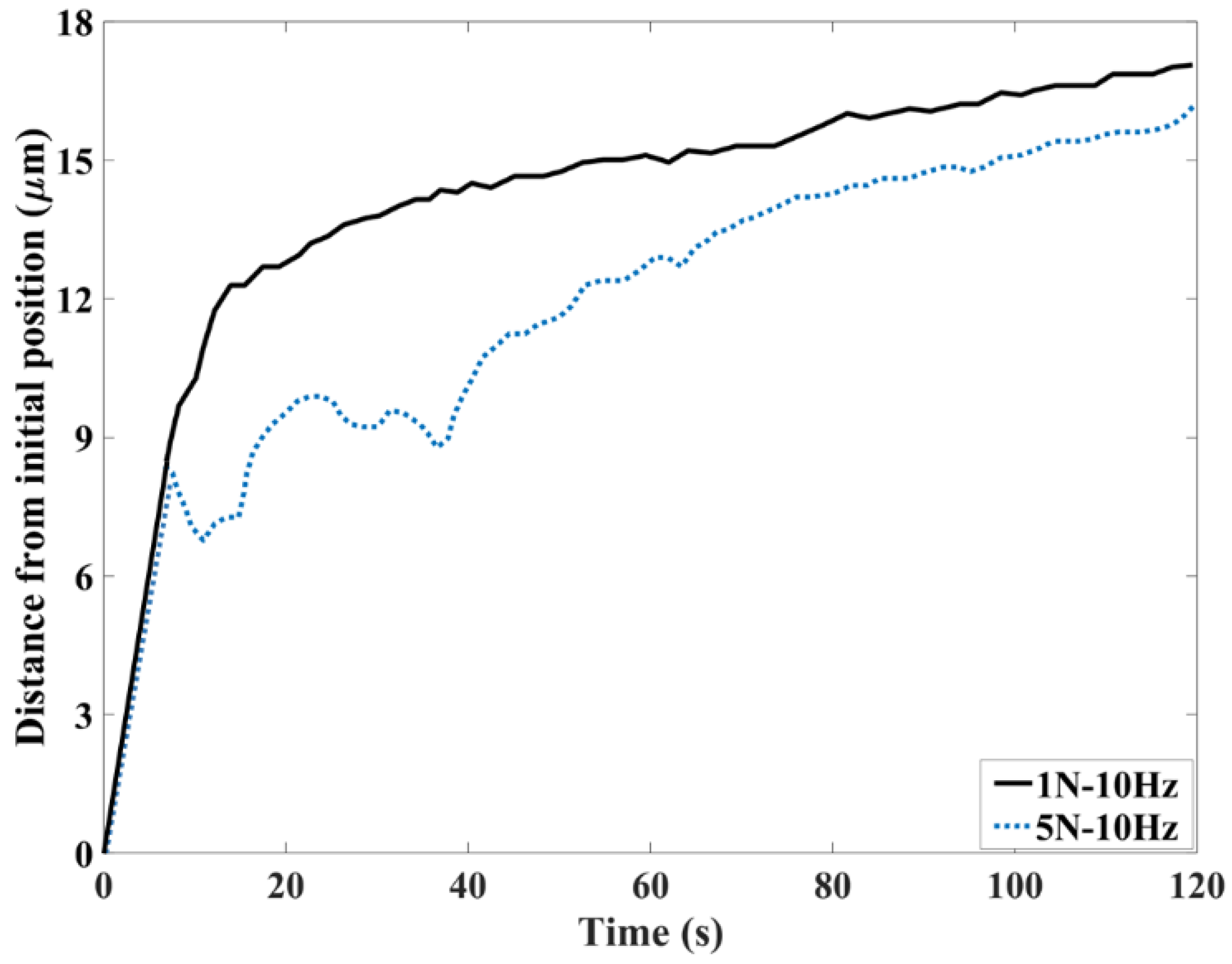
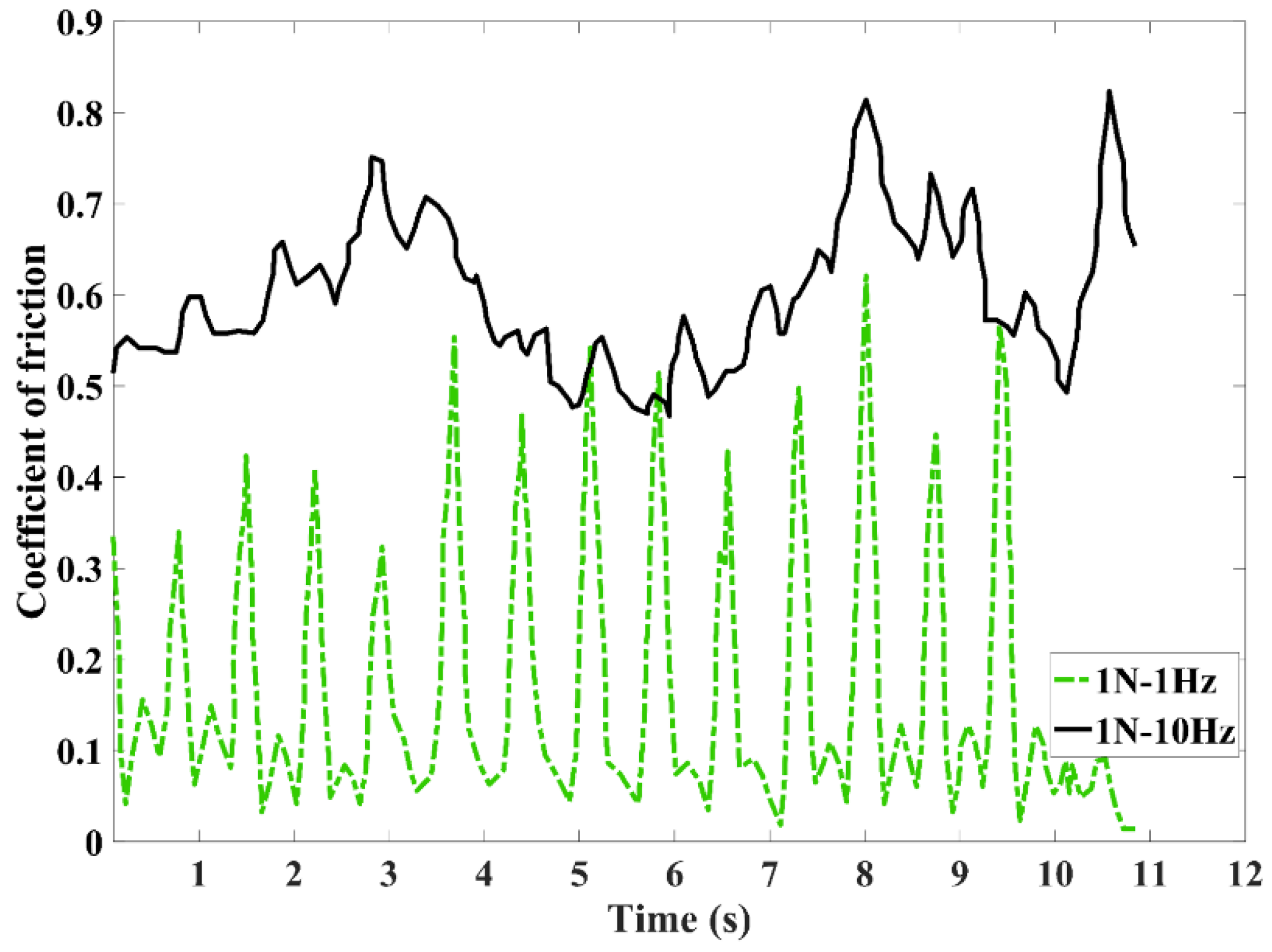
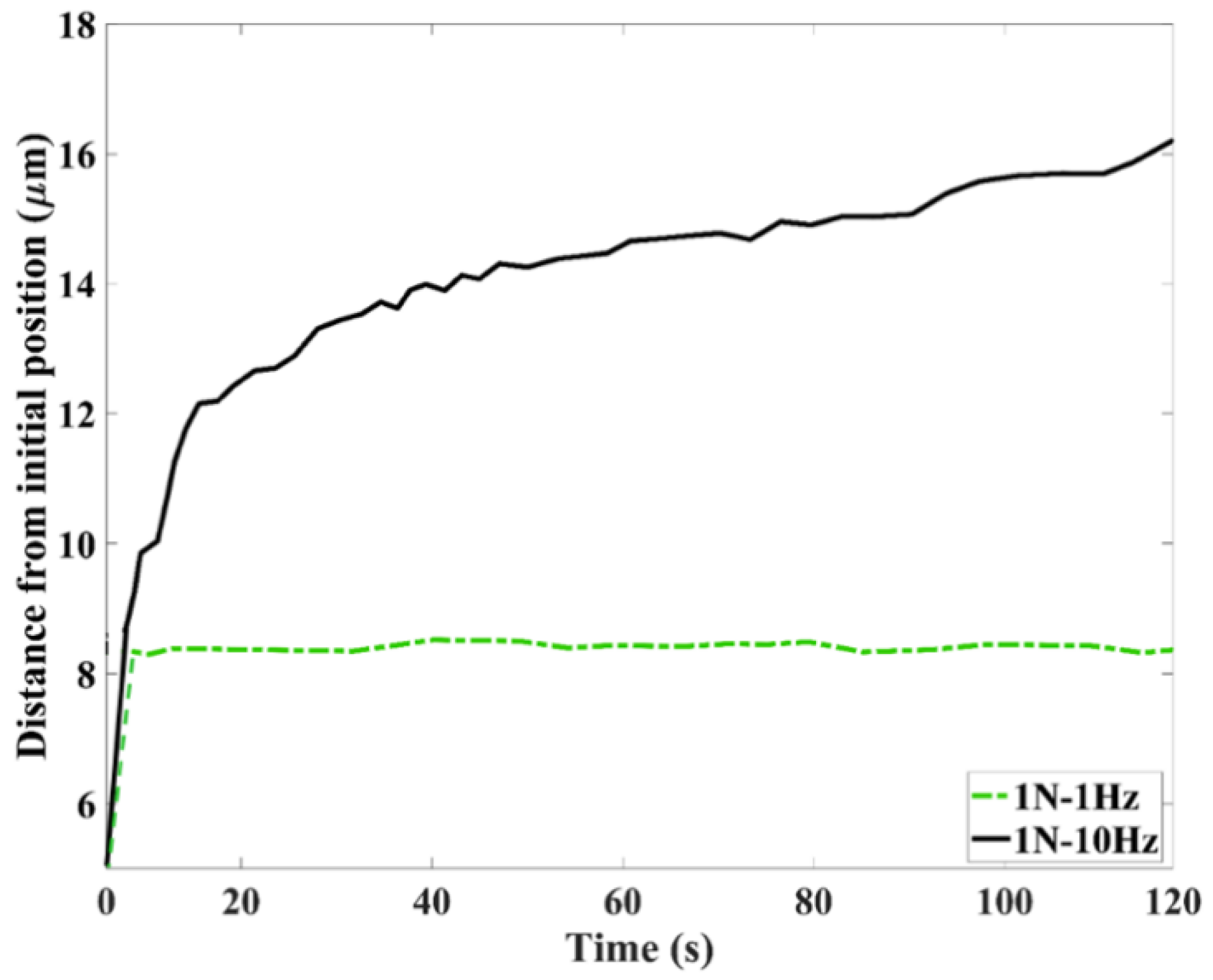
3.2. Effect of Frequency
3.2.1. Coefficient of Friction
3.2.2. Wear
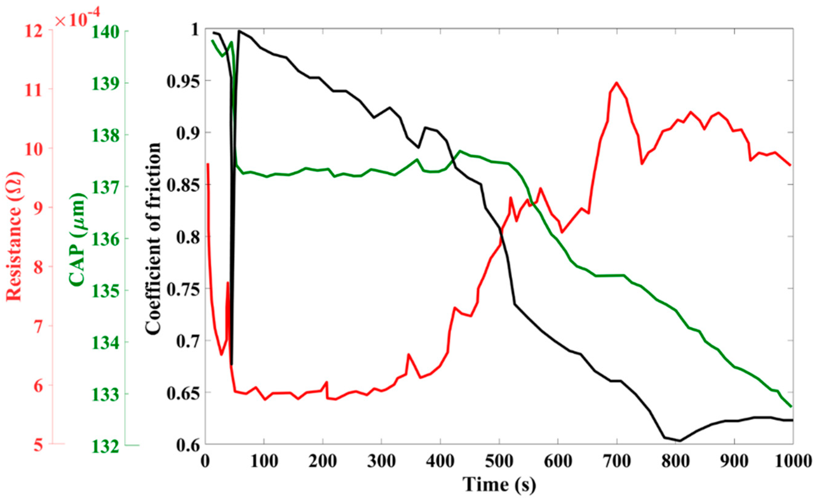
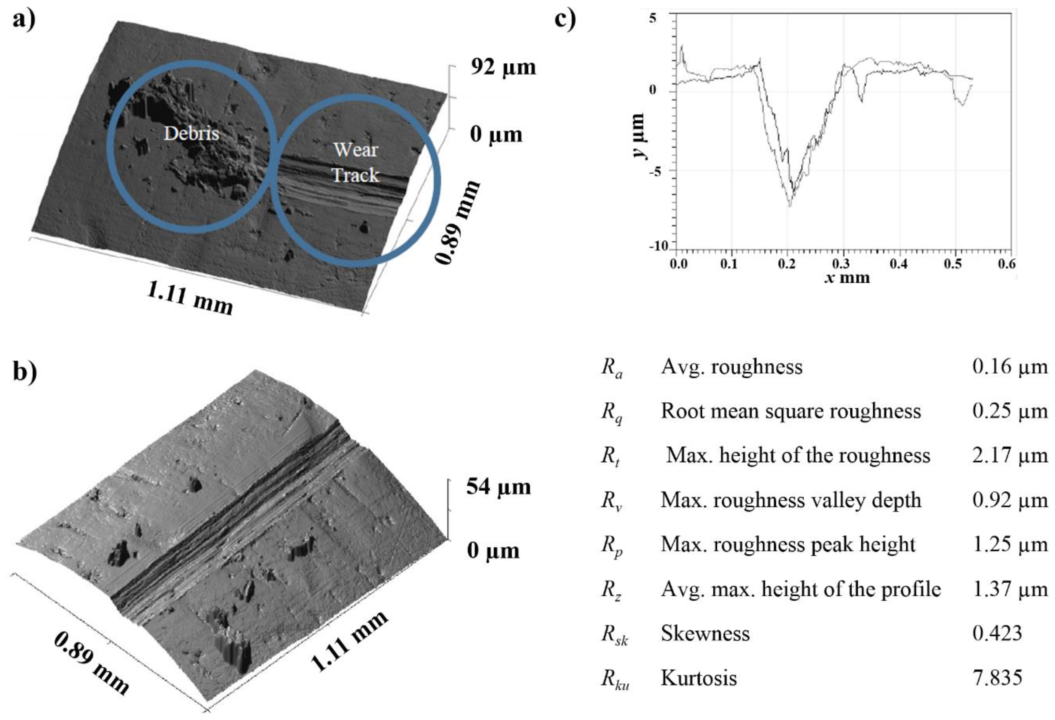
3.2.3. Surface Analysis
4. Conclusions
Author Contributions
Funding
Conflicts of Interest
References
- Pompanon, F.; Laporte, J.; Fouvry, S.; Alquier, O. Normal force and displacement amplitude influences on silver-plated electrical contacts subjected to fretting wear: A basic friction energy–contact compliance formulation. Wear 2019, 426, 652–661. [Google Scholar] [CrossRef]
- Larsson, E.; Andersson, A.M.; Kassman Rudolphi, Å. Grease lubricated fretting of silver coated copper electrical contacts. Wear 2017, 376, 634–642. [Google Scholar] [CrossRef]
- Laporte, J.; Perrinet, O.; Fouvry, S. Prediction of the electrical contact resistance endurance of silver-plated coatings subject to fretting wear, using a friction energy density approach. Wear 2015, 330, 170–181. [Google Scholar] [CrossRef]
- Bock, E.M.; Whitley, J.H. Fretting corrosion in electric contacts. In Proceedings of the Twentieth Annual Holm Seminar on Electrical Contacts, Chicago, IL, USA, 29–31 October 1974; pp. 128–138. [Google Scholar]
- Mason, W.P.; White, S.D. New Techniques for Measuring Forces and Wear in Telephone Switching Apparatus. Bell Syst. Tech. J. 1952, 31, 469–503. [Google Scholar] [CrossRef]
- Liu, X.; Cai, Z.; Liu, S.; Wu, S.; Zhu, M. Influence of Wear Test Parameters on the Electrical Contact Performance of Brass Alloy/Copper Contactors Under Fretting Wear. J. Mater. Eng. Perform. 2019, 28, 817–827. [Google Scholar] [CrossRef]
- Laporte, J.; Fouvry, S.; Alquier, O. Prediction of electrical contact resistance failure of Ag/Ag plated contact subjected to complex fretting-reciprocating sliding. Wear 2017, 376, 656–669. [Google Scholar] [CrossRef]
- Saka, N.; Liou, M.J.; Suh, N.P. The role of tribology in electrical contact phenomena. Wear 1984, 100, 77–105. [Google Scholar] [CrossRef]
- Braunovic, M. Surface Analysis of Fretting Damage in Electrical Connectors. In New Materials Approaches to Tribology: Theory and Applications (1988); Materials Research Society: Pittsburgh, PA, USA, 1988; Volume 140, pp. 405–412. [Google Scholar]
- Kogut, L.; Etsion, I. Electrical Conductivity and Friction Force Estimation in Compliant Electrical Connectors. Tribol. Trans. 2000, 43, 816–822. [Google Scholar] [CrossRef]
- Perrinet, O.; Fouvry, S.; Alquier, O. Application of the Friction Energy Density Approach to Predict Electrical Contact Endurance in a Silver-Plated Coating Subjected to Fretting Wear. In Proceedings of the 2013 IEEE 59th Holm Conference on Electrical Contacts (Holm 2013), Newport, RI, USA, 22–25 September 2013; pp. 1–10. [Google Scholar]
- Ren, W.; Wang, P.; Song, J.; Zhai, G. Effects of current load on wear and fretting corrosion of gold-plated electrical contacts. Tribol. Int. 2014, 70, 75–82. [Google Scholar] [CrossRef]
- Antler, M.; Drozdowicz, M.H. Fretting corrosion of gold-plated connector contacts. Wear 1981, 74, 27–50. [Google Scholar] [CrossRef]
- Belakhdar, R.; Noël, S.; Alamarguy, D.; Schneegans, O.; Boccaletti, G. Effect of fluorinated lubricants on the friction modes of tin electrical contacts submitted to fretting. Eur. Phys. J.-Appl. Phys. 2010, 49, 22903. [Google Scholar] [CrossRef]
- Park, Y.W.; Narayanan, T.S.N.S.; Lee, K.Y. Fretting corrosion of tin-plated contacts. Tribol. Int. 2008, 41, 616–628. [Google Scholar] [CrossRef]
- Heitz, E. Fretting Corrosion. Von, R. B. Waterhouse. 253 S. 306 Abb., 13 Tab. 1972, Pergamon Press, Oxford, New York, Toronto, Sydney, Braunschweig. Geb. Mater. Corros. 1975, 26, 172–173. [Google Scholar]
- Hurricks, P.L. The mechanism of fretting—A review. Wear 1970, 15, 389–409. [Google Scholar] [CrossRef]
- Braunovic, M. Fretting in Electrical/Electronic Connections: A Review. IEICE Trans. Electron. 2009, 92, 982–991. [Google Scholar] [CrossRef]
- Myshkin, N.K. Tribological problems in electrical contacts. Tribol. Int. 1991, 24, 45–49. [Google Scholar] [CrossRef]
- Puttock, M.J.; Thwaite, E.G. Elastic compression of spheres and cylinders at point and line contact. In Elastic Compression of Spheres and Cylinders at Point and Line Contact; Puttock, M.J., Thwaite, E.G., Eds.; Commonwealth Scientific and Industrial Research Organization: Melbourne, Australia, 1969; p. 11. [Google Scholar]
- Braunovic, M. Effect of contact load on the contact resistance behavior of different conductor and contact materials under fretting conditions. In Proceedings of the International Conference on Electrical Contact Phenomena, Nuremberg, Germany, 14–17 September 1998; Schröder, K.-H., Ed.; VDE-Verlag: Nuremberg, Germany, 1998; pp. 283–287. [Google Scholar]
- Lee, A.; Mamrick, M. Fretting corrosion of Tin-plated copper alloy. IEEE Trans. Compon. Hybrids Manuf. Technol. 1987, 10, 63–67. [Google Scholar] [CrossRef]
- Kassman, Å.; Jacobson, S. Surface damage, adhesion and contact resistance of silver plated copper contacts subjected to fretting motion. Wear 1993, 165, 227–230. [Google Scholar] [CrossRef]
- Wang, Q.; Wang, Y.; Wang, H.; Fan, N.; Yan, F. Experimental investigation on tribological behavior of several polymer materials under reciprocating sliding and fretting wear conditions. Tribol. Int. 2016, 104, 73–82. [Google Scholar] [CrossRef]
- Trinh, K.E.; Ramos-Moore, E.; Green, I.; Pauly, C.; Zamanzade, M.; Mucklich, F. Topographical and Microstructural Effects of Laser Surface Texturing on Tin-Coated Copper Electrical Connectors under Load Cycling. IEEE Trans. Compon. Packag. Manuf. Technol. 2017, 7, 582–590. [Google Scholar] [CrossRef]
- Menezes, P.L.; Ingole, S.P.; Nosonovsky, M.; Kailas, S.V.; Lovell, M.R. Tribology for Scientists and Engineers; Springer: Berlin/Heidelberg, Germany, 2013; pp. 9–28. [Google Scholar]
- Gallego, L.; Nélias, D. Modeling of Fretting Wear under Gross Slip and Partial Slip Conditions. J. Tribol. 2007, 129, 528–535. [Google Scholar] [CrossRef]
- Vincent, L.; Berthier, Y.; Godet, M. Testing Methods in Fretting Fatigue: A Critical Appraisal. In Standardization of Fretting Fatigue Test Methods and Equipment; Attia, M.H., Waterhouse, R.B., Eds.; ASTM International: West Conshohocken, PA, USA, 1992; pp. 33–48. [Google Scholar]


© 2019 by the authors. Licensee MDPI, Basel, Switzerland. This article is an open access article distributed under the terms and conditions of the Creative Commons Attribution (CC BY) license (http://creativecommons.org/licenses/by/4.0/).
Share and Cite
Siddaiah, A.; Kasar, A.K.; Khosla, V.; Menezes, P.L. In-Situ Fretting Wear Analysis of Electrical Connectors for Real System Applications. J. Manuf. Mater. Process. 2019, 3, 47. https://doi.org/10.3390/jmmp3020047
Siddaiah A, Kasar AK, Khosla V, Menezes PL. In-Situ Fretting Wear Analysis of Electrical Connectors for Real System Applications. Journal of Manufacturing and Materials Processing. 2019; 3(2):47. https://doi.org/10.3390/jmmp3020047
Chicago/Turabian StyleSiddaiah, Arpith, Ashish K. Kasar, Vishal Khosla, and Pradeep L. Menezes. 2019. "In-Situ Fretting Wear Analysis of Electrical Connectors for Real System Applications" Journal of Manufacturing and Materials Processing 3, no. 2: 47. https://doi.org/10.3390/jmmp3020047
APA StyleSiddaiah, A., Kasar, A. K., Khosla, V., & Menezes, P. L. (2019). In-Situ Fretting Wear Analysis of Electrical Connectors for Real System Applications. Journal of Manufacturing and Materials Processing, 3(2), 47. https://doi.org/10.3390/jmmp3020047