Article

Fabrication of Demineralized Bone Matrix/Polycaprolactone Composites Using Large Area Projection Sintering (LAPS)

1
Department of Mechanical Engineering, University of South Florida, 4202 E Fowler Ave, Tampa, FL 33620, USA
2
Department of Chemical Engineering, University of Massachusetts Amherst, Amherst, MA 01003, USA
3
LifeLink Foundation, 9661 Delaney Creek Blvd, Tampa, FL 33619, USA
4
Department of Mechanical Engineering, Brigham Young University, Provo, UT 84602, USA
*
Author to whom correspondence should be addressed.
J. Manuf. Mater. Process. 2019, 3(2), 30; https://doi.org/10.3390/jmmp3020030
Submission received: 30 January 2019 / Revised: 21 March 2019 / Accepted: 2 April 2019 / Published: 10 April 2019

Abstract

:
Cadaveric decellularized bone tissue is utilized as an allograft in many musculoskeletal surgical procedures. Typically, the allograft acts as a scaffold to guide tissue regeneration with superior biocompatibility relative to synthetic scaffolds. Traditionally these scaffolds are machined into the required dimensions and shapes. However, the geometrical simplicity and, in some cases, limited dimensions of the donated tissue restrict the use of allograft scaffolds. This could be overcome by additive manufacturing using granulated bone that is both decellularized and demineralized. In this study, the large area projection sintering (LAPS) method is evaluated as a fabrication method to build porous structures composed of granulated cortical bone bound by polycaprolactone (PCL). This additive manufacturing method utilizes visible light to selectively cure the deposited material layer-by-layer to create 3D geometry. First, the spreading behavior of the composite mixtures is evaluated and the conditions to attain improved powder bed density to fabricate the test specimens are determined. The tensile strength of the LAPS fabricated samples in both dry and hydrated states are determined and compared to the demineralized cancellous bone allograft and the heat treated demineralized-bone/PCL mixture in mold. The results indicated that the projection sintered composites of 45–55 wt %. Demineralized bone matrix (DBM) particulates produced strength comparable to processed and demineralized cancellous bone.

1. Introduction

Treatment of the large bone voids caused by trauma, aging or disease is a challenge. Healing is promoted when such voids are filled with scaffolds that strive to closely mimic the natural tissue. The biocompatibility coupled with mechanical stiffness to match the pore structure of the scaffold structures are key factors for bone replacements [1].
Thus far, many researchers have reported successful creation of porous structures with synthetic materials as a substitute for the spongy architecture of the bone. Instances of such efforts include: Emulsion freezing/freeze-drying [2], solvent-casting/particulate leaching [3], gas foaming [4] and fiber bonding [5]. Another traditional solution to treat orthopedic defects is machining bone allografts into standard clinical shapes from donated cadaveric bone. This approach is advantageous over synthetic materials since it matches the internal architecture, mechanical properties and has excellent osseointegration [6]. However, the allografts are available in only a limited range of geometries and must fit the envelope of a donated bone. For example, it would be difficult to find a sufficiently large allograft in emergency situations where a patient’s anatomy necessitates supplying a fairly large bone allograft scaffold. All these methods share the weaknesses of a limited ability to produce complex geometries [7].
With additive manufacturing (AM) technologies, forming complex features is not a challenge. Various AM techniques including selective laser sintering [8,9], stereolithography [10,11], ink-jet printing [12,13,14] and fused deposition modeling (FDM) [15,16,17] have been used to fabricate scaffolds for bone ingrowth. In some cases, reinforcing [16,18] or bioactive agents [19,20,21] are added into the base material to improve the mechanical and biological properties of the scaffolds.
Hung et al. utilized extrusion based additive manufacturing to fabricate pure polycraprolactone (PCL) and demineralized bone matrix (DBM)/PCL hybrid scaffolds. They demonstrated that the hybrid scaffolds enhanced the healing process within one to three months after transplantation [19]. Although extrusion based methods showed good capability to create complex geometries, the contamination of the DBM scaffold is still a problem that necessitates a vigorous cleaning process or components replacement when switching the source of the donated bone. Further, the filament must be void-free to allow smooth printing. Therefore, the pore creation can only be performed by incorporating the voids into a CAD model. This limits pore sizes to the minimum feature resolution of the printer. This can be circumvented by adding temporary space holders to be removed in a secondary process, but this introduces additional biocompatibility concerns [22]. Such deficiencies created an impetus to explore a new layerwise AM method to process DBM/PCL hybrid powders with no guest substance to form the pores.
Large area projection sintering (LAPS) is a novel layerwise AM process that utilizes powdered raw materials [23]. LAPS utilizes visible light energy to selectively pattern the image onto the powder bed to build the 3D geometry. The light heats the powder to melt the embedded PCL in the exposed areas and create the 2D slices layer-by-layer. In the LAPS process, the PCL/DBM powder mixture is fused together by melting the PCL. By processing in a powder bed, significant open porosity is maintained which is expected to improve healing and osseointegration compared to Hung et al.
This work explores the ability of cadaveric bone and polymer (polycraprolactone) composites to replicate the mechanical properties of demineralized bone allografts. It is expected that the inherent porosity of the fabricated composite will allow the formation of pores below the printing resolution itself and expedite the bone regeneration process due to the biological cues to the recipients’ cells from the bone tissue [19]. The LAPS method also allows for close temperature control that minimizes heating of the DBM to preserve biological functionality and can produce structures that approximate the stiffness of DBM specimens currently used for tissue scaffolds.

2. Experimental Procedure

2.1. Materials

Donated cadaveric bone was processed at LifeLink Tissue Bank, where a proprietary clinical cleaning process was used to remove the blood, lipids, viable cells and micro-organisms. The cortical bone was further processed by grinding to create a coarse powder in the millimeter and micron range following Lifelink standard procedures. The PCL was purchased from Polyscience Inc. with an average particle size of approximately 600 µm and a molecular weight of 50,000 with a melting point of ~60 °C. In order to improve the printing resolution and decrease the minimum layer thickness, both as-received materials were sieved to eliminate particles larger than 300 µm.

2.2. DBM/PCL Ratio Selection

Effective scaffolds require a combination of mechanical strength and bio-functionality. Increasing PCL favors the mechanical properties, but reduces the demineralized bone content and consequently the bioactivity of the structure. To find the minimal PCL content required for adequate mechanical strength, the DBM particulates were mixed with PCL in different ratios to form a homogeneous mixture. The DBM content was varied from 35 wt % to 75 wt % in 5% increments. Rectangular molds were filled with the resultant mixtures and heated to 65 °C (above the melting point of the PCL) for three hours to initiate bonding throughout the samples. Afterwards, the mechanical integrity of each sample was evaluated by checking how readily samples break in handling. The 45 wt %, 50 wt % and 55 wt % DBM mixtures with PCL demonstrated promising strength while maximizing DBM mass fraction. In order to explore the range of interest with a limited number of DBM, the two extreme points of this range (45% and 55% DBM) were selected for all subsequent testing.

2.3. Additive Manufacturing

Powder Bed Formation

The powder bed density and structure play a key role in the final part properties in many powder-based AM processes [24]. Higher spread density results in more inter-particle bonding sites for increased strength and reduced shrinkage in many processes [25]. Although theory provides insight on the optimal powder packing configurations [26,27,28], the powders pack randomly in the layer formation step. So the comprehensive spread behavior of DBM and PCL particles was experimentally studied for the two most commonly used devices to spread powders, the-scraper and roller.
A 3-axis Computer Numerical Control (CNC) table was modified to distribute the powder mixture across the build platform. A small amount of powder was manually deposited on one edge of the powder bed. A traverse speed of 19 mm/s was used with two different leveling methods to spread the powder across the bed. These were a forward rotating roller (press-rolling) and scraper. The rotational speed of the roller was set on ~80 rpm. After each layer, the height of the tool was incremented by the target layer height and the process was repeated. After depositing six layers, a metal cylinder of a known cross-sectional area and a sharp edge was used to isolate a small amount of powder as shown in Figure 1. The mass of the powder was measured. The spread volume was calculated from the cross-sectional area of the cylinder with the height assumed to be six times the layer height. The experiment was repeated three times for each deposition condition to ensure repeatability of the process.
To assess the layer thickness effect on the powder bed density, the materials were first deposited as thick as 1250 µm where the spreading tools leveled the layers uniformly. Then the experiment was repeated for thinner layers to find the lower bound thickness for which the roller and scraper could form uniform layers.
Two groups of samples were created by the LAPS additive manufacturing method for each of the selected powder mixtures—45 wt % and 55 wt % DBM. One series was processed with the lowest possible thickness of the layers as identified in layer formation experiments and the second set was fabricated with 1000 µm layer thickness to see how the layer thickness influences the mechanical properties of the samples.
The source to provide the required energy to cure the PCL was a conventional projector modified to boost the optical intensity to ~1.28 W/Cm2. The 2D image of the tensile bar was projected onto the powder bed and an infra-red camera was used to monitor the curing temperature throughout the process. The image was sustained on the powder bed for approximately 60 s until the temperature reached 65 °C. Temperature variation along the midline of the parts both lengthwise and widthwise varied <5 °C. At this temperature, the PCL melts and consolidates the DBM/PCL mixture. This temperature limit was selected to avoid overheating and degrading the favorable biological features of the DBM. Then the cured layer was allowed to cool down to 30 °C to ensure that the PCL does not bond to the loose powder when depositing the next layer. In total, for the two selected mixture ratios (45 wt % and 55 wt % DBM), two sets of samples were fabricated, one group with the identified lower bound and the second set with a 1000 µm layer thickness. For completion of the samples, six layers were cured and for each condition three to five test coupons were manufactured. The schematic layout of the manufacturing set up and projected image are shown in Figure 2. In the current configuration, the system builds parts at a rate of approximately 30 mm of height per hour. The build rate could be improved by increasing the optical power and/or changing the wavelength of the light that is used to improve absorption.

2.4. Reference Controls

The porous structures made by LAPS are envisioned to be used as a replacement for conventionally fabricated scaffolds. So two different traditional methods were used to create reference samples. As the first reference, three demineralized cancellous bone strips with around 6 mm in thickness were machined into tensile bar shape as shown in Figure 3.
To prepare the second group of reference samples, a mold was printed by using an extrusion based additive manufacturing method such that the virtual dimensions of the resultant samples comply with the ASTM D638-10 standard with a 13 mm gauge width and 3.6 mm thickness. The powder was poured in the mold then heat treated through the isothermal process of 65 °C for three hours. For each powder mixture, four samples were prepared.

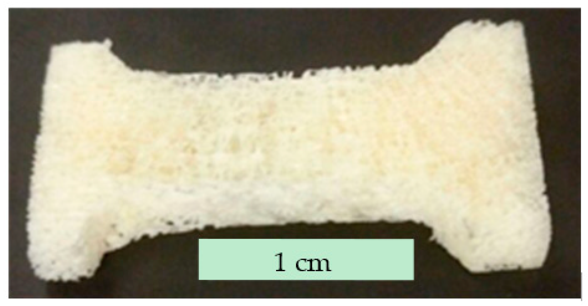
2.5. Sample Preparation for Tensile Testing

Scaffolds must be sufficiently sturdy to survive pre-surgery handling and to realize the biological tasks after implantation. Therefore the strength of the samples was quantified by using a universal hydraulic testing set up. To prevent excessive deformation in gripping, a low viscosity epoxy was infiltrated into the pores in the grip sections of the tensile bars. Each end was dipped in the epoxy resin and then was left at room temperature overnight to be cured. Three to five specimens were prepared for each batch. The induced tensile forces were measured with a 100 lbf load-cell capacity at a grip displacement rate of 1.5 mm/min. The fracture of the samples occurred in the proper part of the sample, approximately in the middle. Tensile properties were measured rather than compression as the tensile properties are more readily measured for thin samples.
Additional sets of the molded DBM/PCL mixtures and the machined demineralized bone samples were prepared by the same process to evaluate the ultimate tensile strength (UTS) change in the hydrated state to mimic the body environment. Therefore the dry samples were immersed for 30 min in a solution of 8% NaCl by weight in deionized water [29]. The tensile strength was measured immediately after removal. In addition to the hybrid samples, pure PCL samples were prepared using the molds and then tested to determine the upper bound of the mechanical strength.

3. Results and Discussion

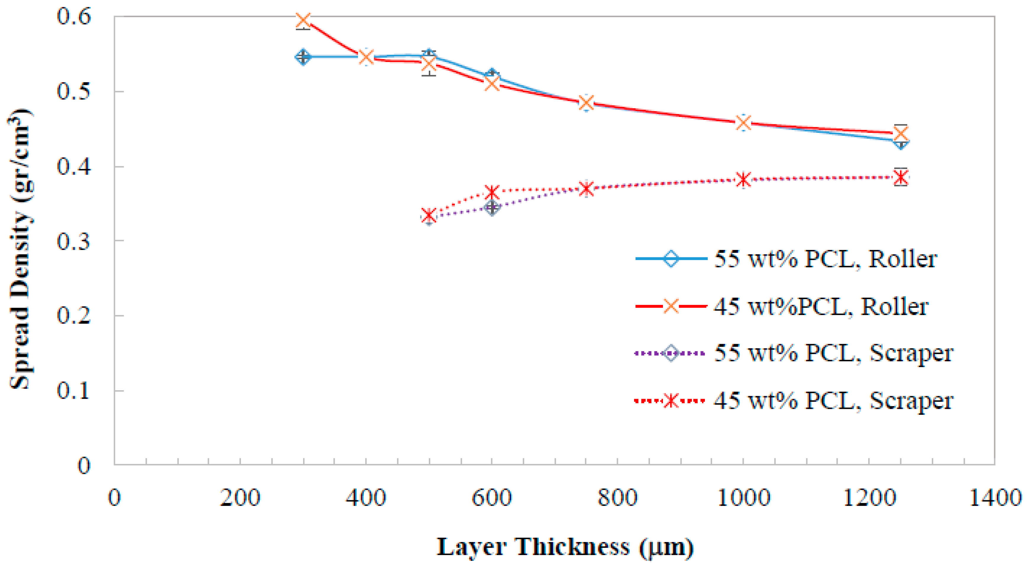
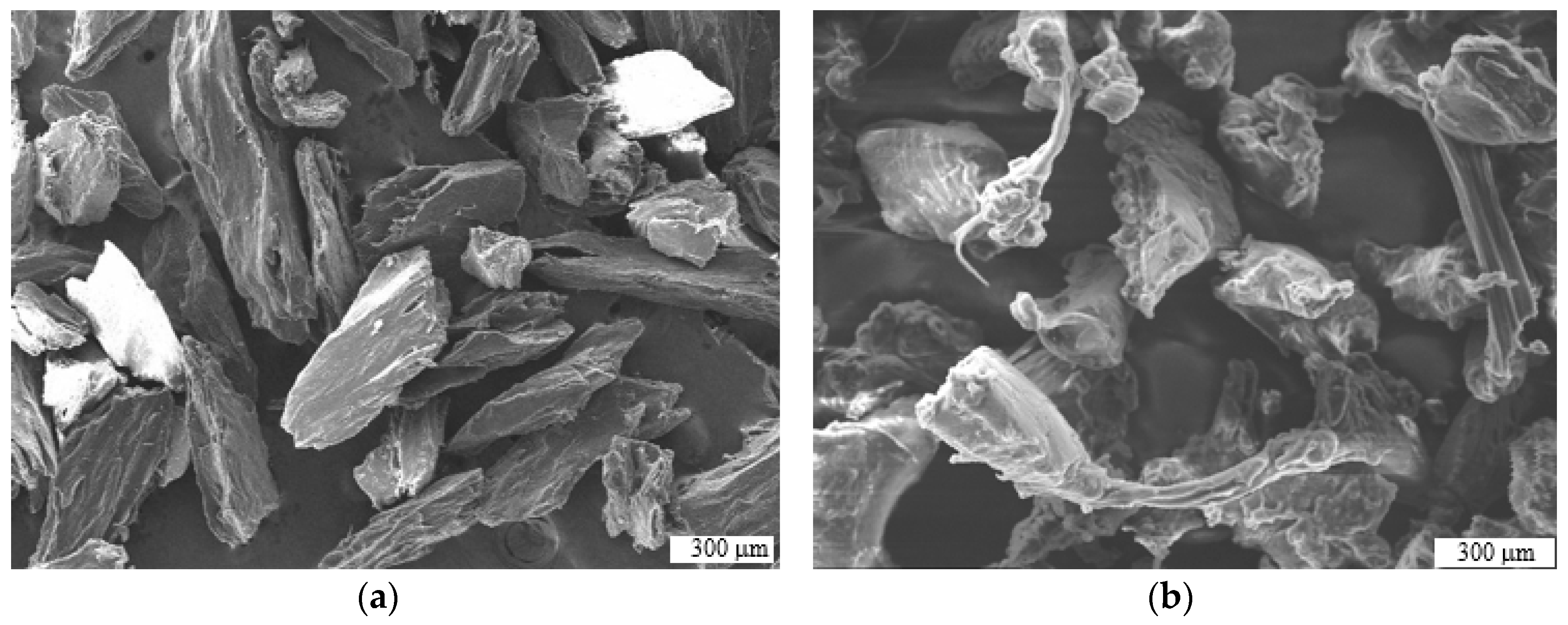
3.1. Optimal Conditions for Bed Formation

The results of the material layering experiments (Figure 4) indicated that, regardless of the demineralized bone fraction in composites, the packing level of the layers were correlated to the spreading tool and the layer thickness. The results demonstrated that the roller spreads denser layers than scraper methodology. It was also able to create thinner layers (300 µm) when compared against the scraper (500 µm) as the lower bound of layer formation. These differences can be attributed to the contact dynamic of the spreader tools with the material [30].
The rotational movement of the roller induces friction between the roller and powders and aligns the asymmetric powder particles in the plane. Increasing layer thickness reduced powder bed density suggesting that the alignment is less effective in thicker layers. Additionally, it was observed that the powder bed had some springback after the roller passed over. This resulted in an overestimate of the powder bed density since the height was assumed to be the layer thickness times the number of layers.
On the other hand, the scraper had a short acting time on the materials and induced less shear stress making this device less effective to realign the particles. The microscopic images of the materials shown in Figure 5 indicate that the sieved particles have an irregular rod shape with less than 300 µm in one direction but approaching 1 mm in length. Thus, it is expected that in forming thin layers, a larger fraction of the particles get displaced by the scraper. This reduces the spread density and has an increased impact at thinner layers. Thus the scraper requires a larger layer thickness increase compared to the roller case. At thicker layers, the density from the two methods seemed to be approaching the same value with decreasing differences. Generally spherical powders are preferred in powder bed AM for improved spreading but non-spherical powders have been used in other cases [31]. The particle shape may also impact the bonding network between the polymer and DBM. If the particle shape is changed, the ideal concentrations may be altered.

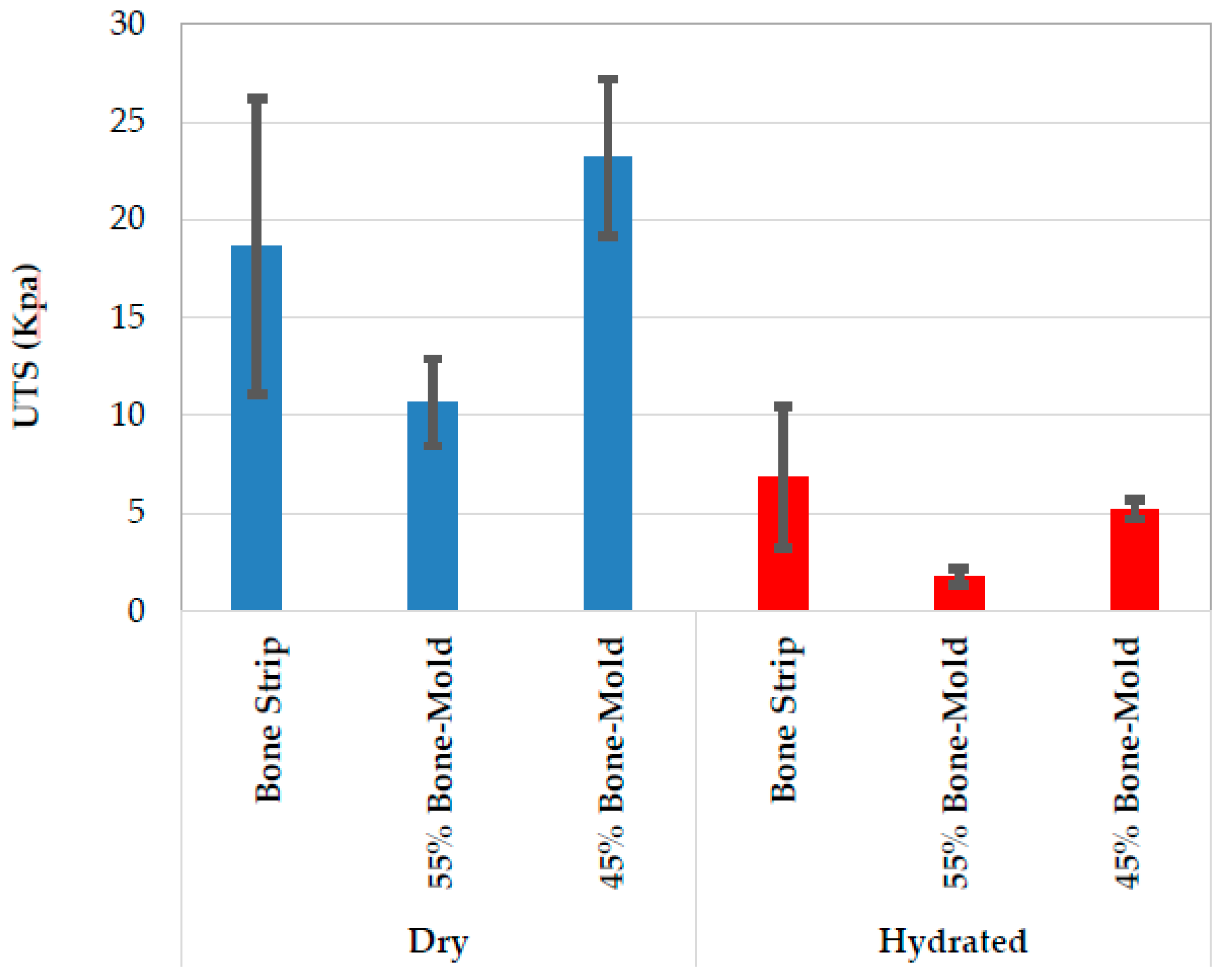
3.2. Mechanical Characterization

As shown in Figure 6, the ultimate tensile strength (UTS) varied significantly based on the fabrication method, layering condition and scaffold composition. The hybrid DBM/PCL samples made by LAPS showed comparable mechanical strength with the demineralized cancellous bone and mold samples. Considering the results for each set of additively fabricated samples, it is clear that the layer thickness plays an important role on the UTS. For both powder mixtures, the UTS magnitude increased by nearly double when the layers’ thickness reduced from 1000 µm to the least thickness of each compound, i.e., 300 µm and 500 µm for 55 wt % and 45 wt % DBM compounds, respectively. This was consistent with the expectation that a closely packed powder bed would create a sample with improved mechanical properties.
Further, comparing the results for LAPS-fabricated to the molded samples revealed that for each DBM/PCL powder stock if the samples are made layerwise with the identified thin layer, they show better mechanical characteristics than the molded samples. The molded strengths were comparable to the 1 mm thick layers. This was consistent with the layer density measurements suggesting that the part thickness is reaching a limiting density at thicknesses above 1 mm. The molded samples could be considered as a single 6 mm thick layer. In addition to having greater strength, the LAPS additive manufacturing method can be potentially manipulated to form scaffolds with fairly complex geometries and features [23]. The strength and the resolution in the Z-direction from one side and the fabrication rate from the other side are the tradeoffs that need to be determined according to the needs.
It is evident that the PCL content plays a key role in the mechanical strength in both the LAPS and mold method based on the significant difference in the strength for 45% and 55% DBM fractions. Over the range of compositions studied, there is a nonlinear increase in strength with PCL concentration. This may be due to reaching a critical concentration at which the PCL is able to form a bonded structure. This is analogous to observations of particle loading required for achieving electrical conductivity [32]. A micro-image of the fracture surface (Figure 7) indicated a significant deformation in PCL fibers due to the tensile testing before failure.
The mechanical characteristics of the hydrated samples were compared to that of the dry state as shown in Figure 8. For reference, the UTS of a cast specimen of PCL is 129.9 kPa. In general, all sample groups weakened significantly after hydration. For the machined demineralized bone strips, the UTS dropped by ~30 times compared to the dry state, consistent with prior observations [33]. For DBM/PCL hybrids, however, the hydration impact was reduced and there was an inverse relationship between the PCL content of the samples and the relative reduction of UTS. Based on the increased strength of LAPS samples compared to molded samples, it is reasonable to expect that both 45 wt % and 55 wt % DBM samples will be able to produce adequate hydrated strength to replicate the bone strips.

4. Conclusions

Composites of PCL and cortical bone particulate can create highly porous scaffolds for orthopedic applications. The study illustrated the two promising mixture ratios for creating scaffolds for both mechanical and clinical needs. A demineralized bone fraction between 45–55 wt % was identified as the mixture ratio that resulted in sufficient mechanical properties for handling while containing significant demineralized bone particles to aid bio-integration. Mechanical testing of the samples made with these two ratios demonstrated that an increased PCL content improves the mechanical properties. The UTS of specimens produced by LAPS largely depends on the layer thickness. The samples composed of 1000 µm thick layers showed comparable strength to the molded specimens with identical materials. The UTS improved when processing in thinner layers. This is possibly due to the increase in spread density. Hydration reduced the UTS of the composite specimens less than the demineralized cancellous bone. Overall, the results demonstrated that DBM/PCL composites produced with the LAPS additive manufacturing methodology have suitable mechanical properties to create patient-specific implants. The tested compositions appear to bracket the mechanical properties of 100% DBM samples in the dry while 45% bone provides a good match to machined DBM when hydrated. A 50% mixture might be preferred to have a higher bone content while better approximating the machined specimen mechanical properties. Future work will address the biological performance of these composites and methods of controlling the resulting pore structures.

Author Contributions

M.Z. performed the experiments and analyzed the data; R.H. contributed in performing the experiments and analyzing the data on layer spreading; A.M. provided guidance on the impact of clinical and regulatory requirements to the process and proposed the project goal; N.B.C. supervised the project and designed the methodology to accomplish this research; M.Z. and N.B.C. wrote the paper.

Funding

This research was funded by LifeLink foundation.

Acknowledgments

We would like to thank LifeLink foundation to providing funding and the required materials for this study.

Conflicts of Interest

The authors declare no conflict of interest.

References

  1. Chen, A.A.; Tsang, V.L.; Albrecht, D.R.; Bhatia, S.N. 3-D Fabrication Technology for Tissue Engineering. In BioMEMS and Biomedical Nanotechnology: Volume III Therapeutic Micro/Nanotechnology; Ferrari, M., Desai, T., Bhatia, S., Eds.; Springer: Boston, MA, USA, 2007; pp. 23–38. [Google Scholar]
  2. Sultana, N.; Wang, M. Fabrication of Tissue Engineering Scaffolds Using the Emulsion Freezing/Freeze-drying Technique and Characteristics of the Scaffolds. In Integrated Biomaterials in Tissue Engineering; John Wiley & Sons, Inc.: Hoboken, NJ, USA, 2012; pp. 63–89. [Google Scholar]
  3. Sin, D.; Miao, X.; Liu, G.; Wei, F.; Chadwick, G.; Yan, C.; Friis, T. Polyurethane (PU) scaffolds prepared by solvent casting/particulate leaching (SCPL) combined with centrifugation. Mater. Sci. Eng. C 2010, 30, 78–85. [Google Scholar] [CrossRef] [Green Version]
  4. Poursamar, S.A.; Hatami, J.; Lehner, A.N.; da Silva, C.L.; Ferreira, F.C.; Antunes, A.P.M. Gelatin porous scaffolds fabricated using a modified gas foaming technique: Characterisation and cytotoxicity assessment. Mater. Sci. Eng. C 2015, 48, 63–70. [Google Scholar] [CrossRef] [PubMed] [Green Version]
  5. Mandal, B.B.; Grinberg, A.; Gil, E.S.; Panilaitis, B.; Kaplan, D.L. High-strength silk protein scaffolds for bone repair. Proc. Natl. Acad. Sci. USA 2012, 109, 7699–7704. [Google Scholar] [CrossRef] [Green Version]
  6. Tada, S.; Stegaroiu, R.; Kitamura, E.; Miyakawa, O.; Kusakari, H. Influence of implant design and bone quality on stress/strain distribution in bone around implants: A 3-dimensional finite element analysis. Int. J. Oral Maxillofac. Implants 2003, 18, 357–368. [Google Scholar]
  7. Chumnanklang, R.; Panyathanmaporn, T.; Sitthiseripratip, K.; Suwanprateeb, J. 3D printing of hydroxyapatite: Effect of binder concentration in pre-coated particle on part strength. Mater. Sci. Eng. C 2007, 27, 914–921. [Google Scholar] [CrossRef]
  8. Liu, F.-H.; Lee, R.-T.; Lin, W.-H.; Liao, Y.-S. Selective laser sintering of bio-metal scaffold. In Proceedings of the 1st CIRP Conference on BioManufacturing, BioM 2013, Tokyo, Japan, 3–5 March 2013; pp. 83–87. [Google Scholar]
  9. Liulan, L.; Aili, T.; Huicun, Z.; Qingxi, H.; Minglun, F. The mechanical properties of bone tissue engineering scaffold fabricating via selective laser sintering. In International Conference on Life System Modeling and Simulation; LSMS 2007; Springer: Berlin/Heidelberg, Germany, 2007; pp. 146–152. [Google Scholar]
  10. Cooke, M.N.; Fisher, J.P.; Dean, D.; Rimnac, C.; Mikos, A.G. Use of stereolithography to manufacture critical-sized 3D biodegradable scaffolds for bone ingrowth. J. Biomed Mater. Res. B 2003, 64B, 65–69. [Google Scholar] [CrossRef] [PubMed]
  11. Kumagai, K.; Asaoka, T.; Furukawa, K.; Ushida, T. Fabrication of scaffold for bone regeneration by taylor made stereolithography. Adv. Sci. Technol. 2013, 86, 70–74. [Google Scholar] [CrossRef]
  12. Cuidi, L.; Li, G.; Fangping, C.; Changsheng, L. Fabrication of mesoporous calcium silicate/calcium phosphate cement scaffolds with high mechanical strength by freeform fabrication system with micro-droplet jetting. J. Mater. Sci. 2015, 50, 7182–7191. [Google Scholar]
  13. Inzana, J.A.; Olvera, D.; Fuller, S.M.; Kelly, J.P.; Graeve, O.A.; Schwarz, E.M.; Kates, S.L.; Awad, H.A. 3D printing of composite calcium phosphate and collagen scaffolds for bone regeneration. Biomaterials 2014, 35, 4026–4034. [Google Scholar] [CrossRef] [PubMed]
  14. Ju-Yeon, L.; Bogyu, C.; Wu, B.; Min, L. Customized biomimetic scaffolds created by indirect three-dimensional printing for tissue engineering. Biofabrication 2013, 5, 045003. [Google Scholar] [Green Version]
  15. Lin, L.; Rong, B.; Hu, Q.; Fang, M. Microstructural Comparison and Analysis of Bone Scaffold Prepared by FDM and SLS Process. In Proceedings of the World Congress on Medical Physics and Biomedical Engineering, Munich, Germany, 7–12 September 2009; pp. 109–112. [Google Scholar]
  16. Sa, M.W.; Nguyen, B.B.; Moriarty, R.A.; Kamalitdinov, T.; Fisher, J.P.; Kim, J.Y. Fabrication and evaluation of 3D printed BCP scaffolds reinforced with ZrO2 for bone tissue applications. Biotechnol. Bioeng. 2018, 115, 989–999. [Google Scholar] [CrossRef]
  17. Yen, H.-J.; Tseng, C.-S.; Hsu, S.-H.; Tsai, C.-L. Evaluation of chondrocyte growth in the highly porous scaffolds made by fused deposition manufacturing (FDM) filled with type II collagen. Biomed. Microdevices 2009, 11, 615–624. [Google Scholar] [CrossRef]
  18. Wang, X.; Jiang, M.; Zhou, Z.; Gou, J.; Hui, D. 3D printing of polymer matrix composites: A review and prospective. Compos. Part B Eng. 2017, 110, 442–458. [Google Scholar] [CrossRef]
  19. Hung, B.P.; Naved, B.A.; Nyberg, E.L.; Dias, M.; Holmes, C.A.; Elisseeff, J.H.; Dorafshar, A.H.; Grayson, W.L. Three-Dimensional Printing of Bone Extracellular Matrix for Craniofacial Regeneration. ACS Biomater. Sci. Eng. 2016, 2, 1806–1816. [Google Scholar] [CrossRef] [Green Version]
  20. La, W.-G.; Jang, J.; Kim, B.S.; Lee, M.S.; Cho, D.-W.; Yang, H.S. Systemically replicated organic and inorganic bony microenvironment for new bone formation generated by a 3D printing technology. RSC Adv. 2016, 6, 11546–11553. [Google Scholar] [CrossRef] [Green Version]
  21. Moloye, T.; Batich, C. Preparation and in vitro characterization of polycaprolactone and demineralized bone matrix scaffolds. In Proceedings of the 2011 MRS Fall Meeting, Boston, MA, USA, 28 November–2 December 2011; pp. 23–28. [Google Scholar]
  22. Singh, S.; Ramakrishna, S. Biomedical Applications of Additive Manufacturing: Present and Future. Curr. Opin. Biomed. Eng. 2017, 2, 105–115. [Google Scholar] [CrossRef]
  23. Nussbaum, G.C.J.; Harmon, J.; Crane, N. Evaluation of the Processing Variables in Large Area Polymer Sintering of Single Layer Components. In Proceedings of the Solid Freeform Fabrication, Austin, TX, USA, 8–10 August 2016. [Google Scholar]
  24. Ziaee, M.; Tridas, E.M.; Crane, N.B. Binder-Jet Printing of Fine Stainless Steel Powder with Varied Final Density. JOM 2017, 69, 592–596. [Google Scholar] [CrossRef]
  25. Jacob, G.; Donmez, A.; Slotwinski, J.; Moylan, S. Measurement of powder bed density in powder bed fusion additive manufacturing processes. Meas. Sci. Technol. 2016, 27, 115601. [Google Scholar] [CrossRef] [Green Version]
  26. Schure, M.R.; Maier, R.S. How does column packing microstructure affect column efficiency in liquid chromatography? J. Chromatogr. A 2006, 1126, 58–69. [Google Scholar] [CrossRef]
  27. Daneyko, A.; Höltzel, A.; Khirevich, S.; Tallarek, U. Influence of the particle size distribution on hydraulic permeability and eddy dispersion in bulk packings. Anal. Chem. 2011, 83, 3903–3910. [Google Scholar] [CrossRef]
  28. Daneyko, A.; Khirevich, S.; Höltzel, A.; Seidel-Morgenstern, A.; Tallarek, U. From random sphere packings to regular pillar arrays: Effect of the macroscopic confinement on hydrodynamic dispersion. J. Chromatogr. A 2011, 1218, 8231–8248. [Google Scholar] [CrossRef]
  29. Kokubo, T.; Kushitani, H.; Sakka, S.; Kitsugi, T.; Yamamuro, T. Solutions able to reproduce in vivo surface-structure changes in bioactive glass-ceramic A-W. J. Biomed. Mater. Res. 1990, 24, 721–734. [Google Scholar] [CrossRef]
  30. Haeri, S. Optimisation of blade type spreaders for powder bed preparation in Additive Manufacturing using DEM simulations. Powder Technol. 2017, 321, 94–104. [Google Scholar] [CrossRef] [Green Version]
  31. Sungail, C.; Abid, A. Spherical tantalum feed powder for metal additive manufacturing. Met. Powder Rep. 2018, 73, 316–318. [Google Scholar] [CrossRef]
  32. Avinash, B.S.; Chaturmukha, V.S.; Jayanna, H.S.; Naveen, C.S.; Rajeeva, M.P.; Harish, B.M.; Suresh, S.; Lamani, A.R. Effect of particle size on band gap and DC electrical conductivity of TiO2 nanomaterial. AIP Conf. Proc. 2016, 1728, 020426. [Google Scholar]
  33. Bembey, A.; Bushby, A.; Boyde, A.; Ferguson, V.; Oyen, M. Hydration effects on the micro-mechanical properties of bone. J. Mater. Res. 2006, 21, 1962–1968. [Google Scholar] [CrossRef]
Figure 1. (a) Illustration of layer formation by two examined spreading tools. (b) Process of using a plug to sample the powder bed to measure spread density.
Jmmp 03 00030 g001
Figure 2. (a) Diagram of the set up used to simulate the large area projection sintering (LAPS) additive manufacturing process. (b) The image projected onto the powder mixture to fabricate each sample. (c) A photograph of the hardware.
Jmmp 03 00030 g002
Figure 3. The machined demineralized bone graft prepared for a tensile test.
Jmmp 03 00030 g003
Figure 4. The variation of the powder bed density when using two spreading tools, the scraper and press rolling method, for different layer thicknesses.
Jmmp 03 00030 g004
Figure 5. The SEM image of the powders sieved down to <300 µm. (a) Demineralized bone particulates and (b) polycaprolactone (PCL) powders. Scale bars represent 300 µm.
Jmmp 03 00030 g005
Figure 6. Comparison of the ultimate tensile strengths for natural cancellous bone and PCL/demineralized bone matrix (DBM) composites fabricated by heating in a mold and LAPS with varied layer thickness. All testing was done in the dry state.
Jmmp 03 00030 g006
Figure 7. SEM image of the PCL fibers at the fracture face of a tensile test of a 55 wt % DBM/PCL mold sample (the view direction is perpendicular to the XY-plane). Scale bar represents 100 µm.
Jmmp 03 00030 g007
Figure 8. Summary of the hydration impact on ultimate tensile strength.
Jmmp 03 00030 g008

