Selection of Machining Parameters Using a Correlative Study of Cutting Tool Wear in High-Speed Turning of AISI 1045 Steel

 ,
,  ,
,  and
and
Abstract
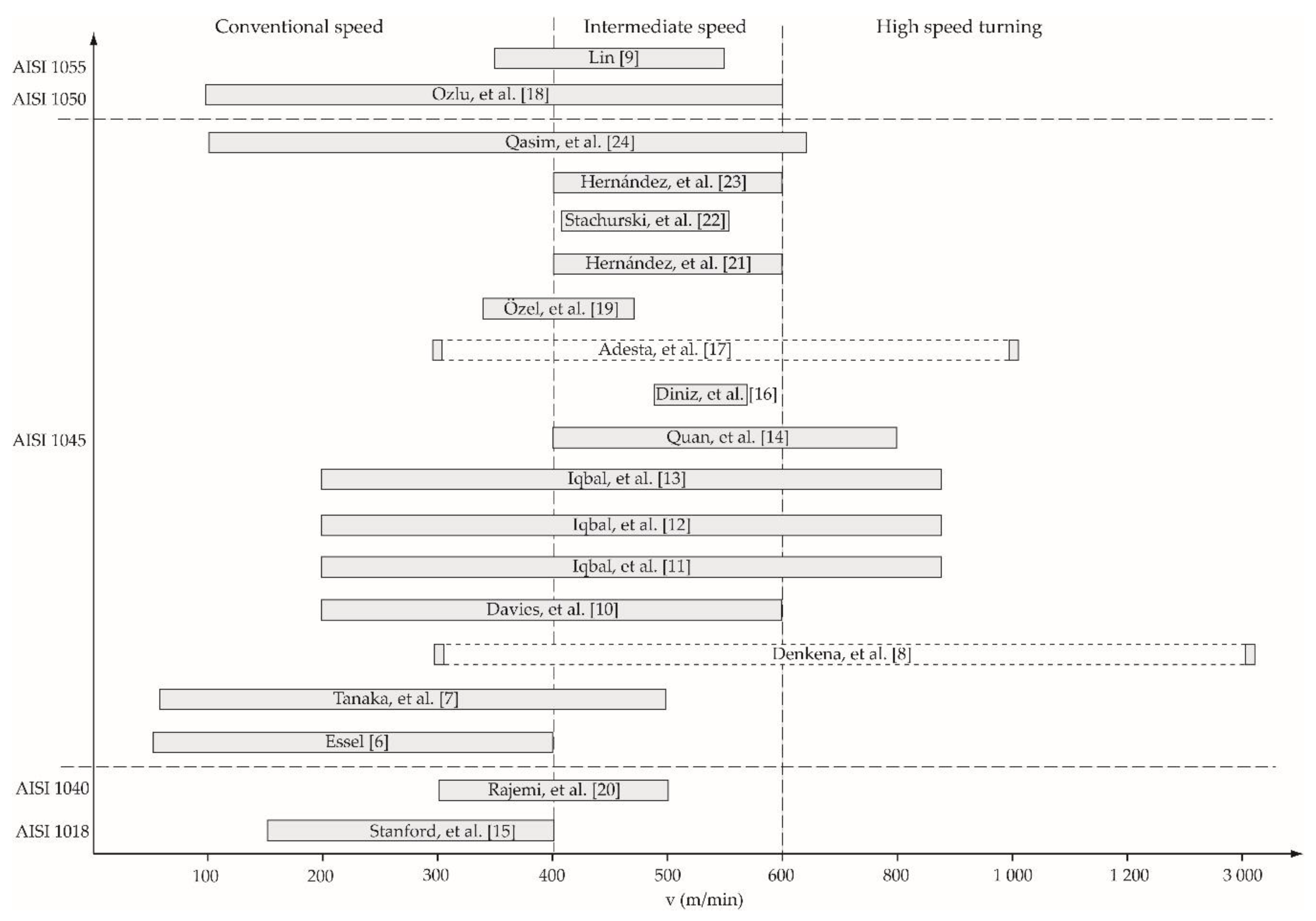
:1. Introduction
- (a)
- Higher cutting speeds increase surface roughness quality but decrease cutting tool life.
- (b)
- Higher feed rates increase productivity as the material removal rate is increased.
- (c)
- Higher feed rates decrease surface roughness quality.
- (d)
- Higher feed rates decrease cutting tool life.
- (e)
- A higher axial depth of cut increases productivity but decreases cutting tool life.
- (f)
- A very low axial depth of cut burns the workpiece surface and generates a low surface roughness quality and decreases cutting tool life.
2. Materials and Methods
2.1. Flank Wear Criterion for Cutting Tool Life Definition
2.2. Sample Characteristics
2.3. Characteristics of Inserts
2.4. Experimental Setup and Factorial Design of the Investigation
3. Experimental Results, Analysis, and Discussion
3.1. Flank Wear Analysis in High-Speed Turning
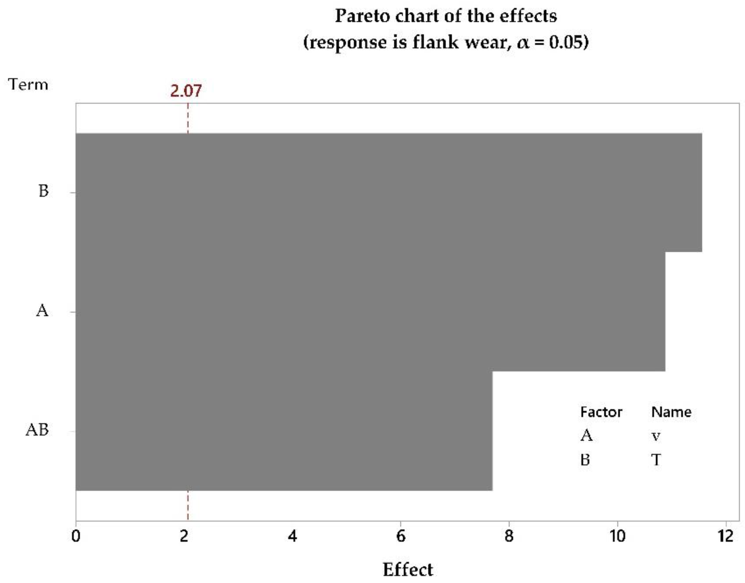
3.2. Analysis of the Design
Determination of Outliers
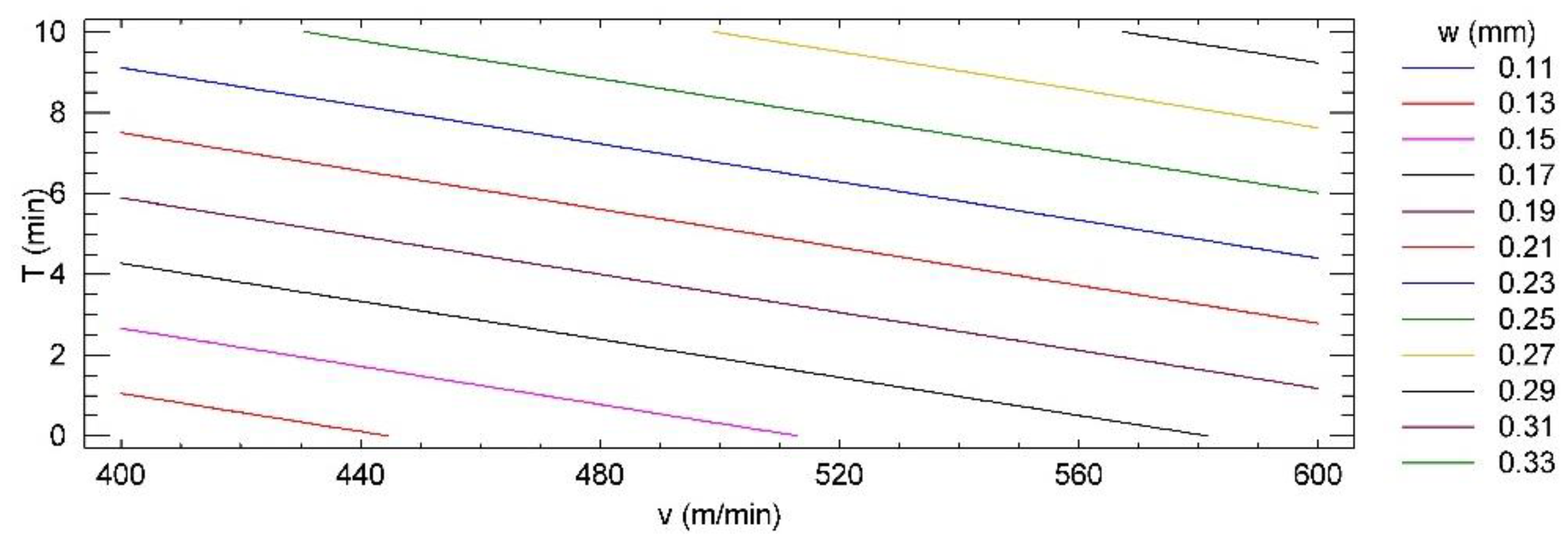
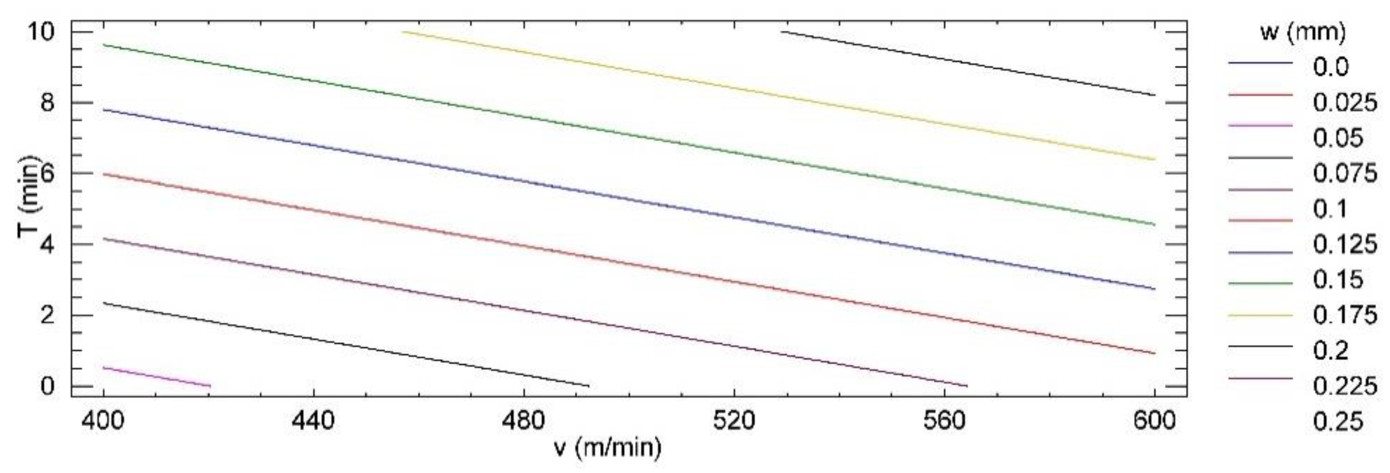
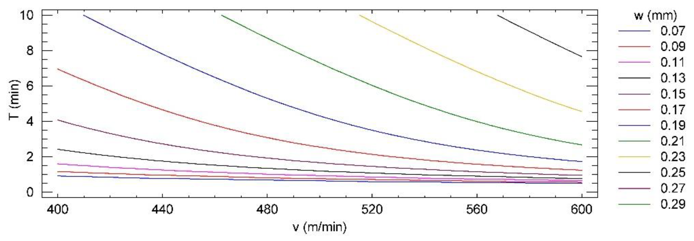
3.3. ContourPlot for the Relation between the Input Factors and Flank Wear of the Cutting Tools
- The coefficient of determination (R2) must be at least greater than 50%.
- The p-value of the analysis of variance of the model is less than 0.05 (there is a statistically significant relationship between the variables with a confidence level at 95.0%).
- The p-value (the probability of t) of the independent variables should be less than 0.05 (statistically significant with a confidence level at 95.0%).
- The basic assumptions of regression analysis [37].
3.4. Determination of the Coefficient of Use of the Inserts
4. Conclusions
- The high-speed dry turning of AISI 1045 steel was performed in order to determine the minimum flank wear area of three cutting tool materials, using the contour graph of the relationship between machining time and cutting speed.
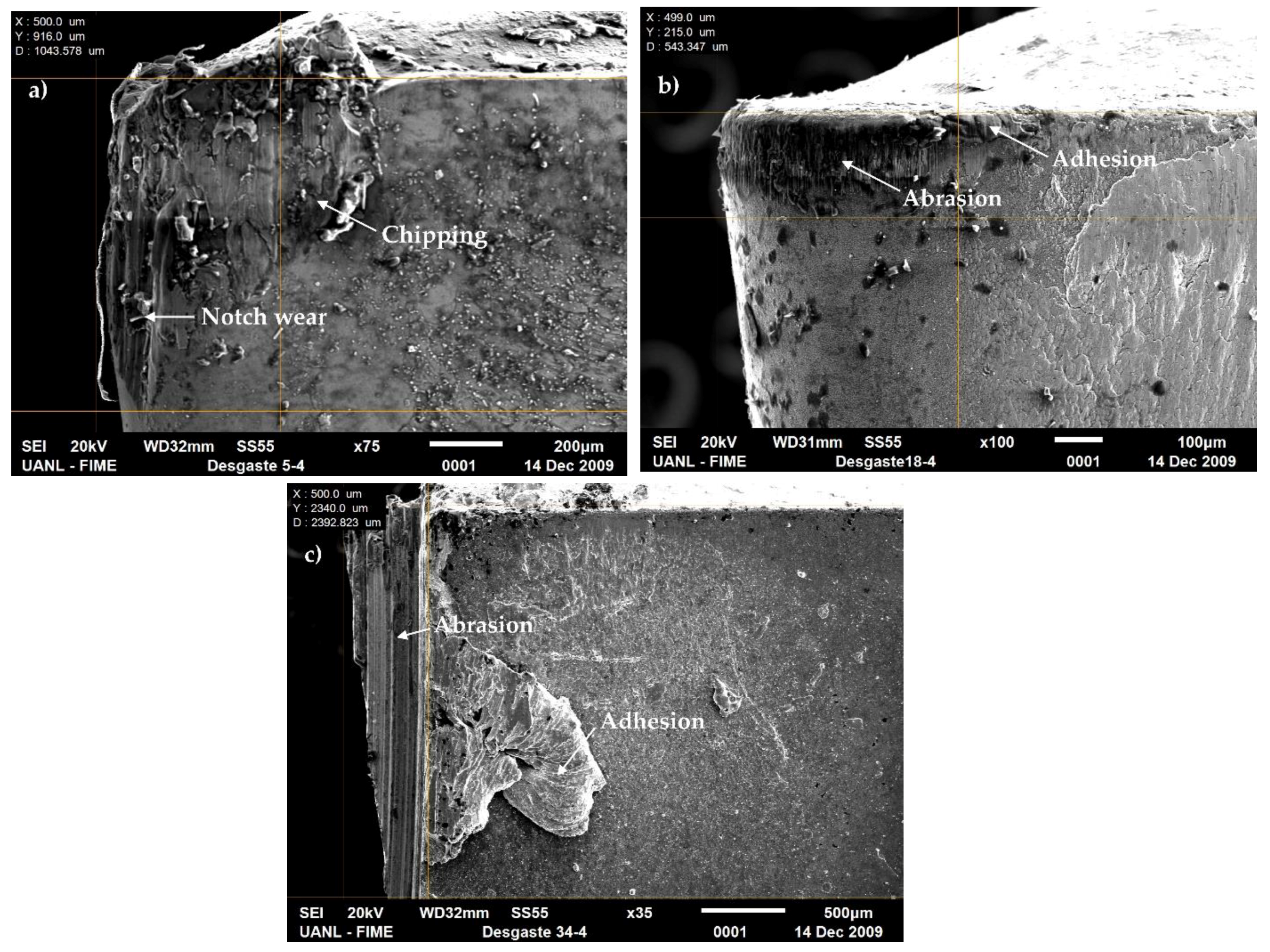
- For high cutting speeds, insert CT5015-P10 exhibited excessive wear revealing abrasion, adhesion, plastic deformation, and chipping. Insert GC4225-P25 also showed significant abrasion, adhesion, plastic deformation and cutting edge fracture, while insert GC4215-P15 showed abrasion and adhesion followed by plastic deformation and chipping.
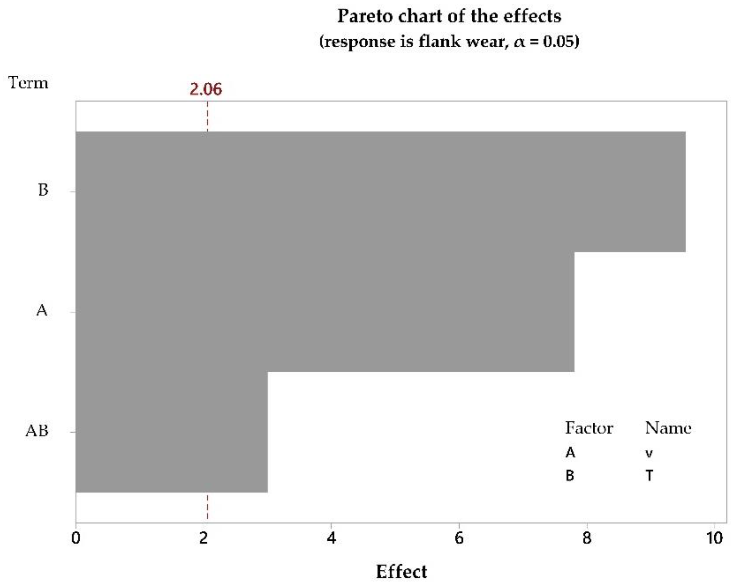
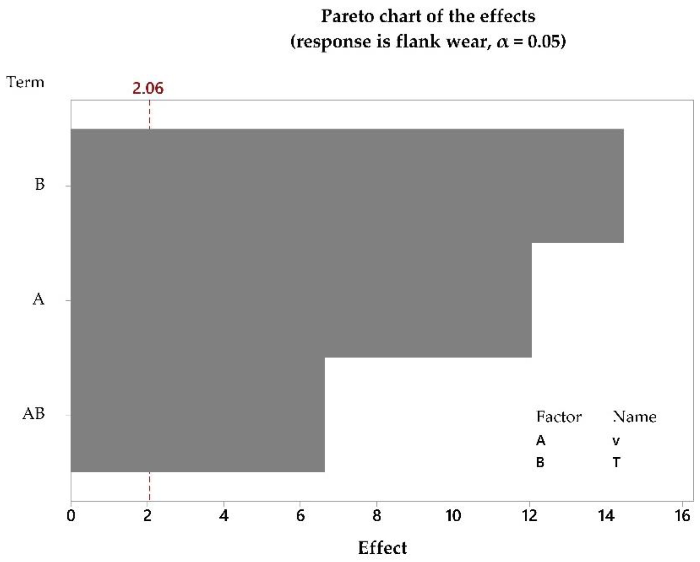
- The models selected for optimization have been validated through the Pareto principle. The Pareto graph showed that the variables (cutting speed, machining time and their interaction), influenced the flank wear of the CT5015-P10, GC4215-P15 and GC4225-P25 inserts. Additionally, the machining time was the most significant factor on flank wear of the cutting tools.
- The three coated GC4215 cutting tool was the best option, since it did not reach the limit of useful life and can be used for the entire range of cutting parameters selected.
- The CT5015 insert is recommended to be used (w < 0.25 mm) for the area of T ≤ 6 min and all value of cutting speed, as well as, for v ≤ 440 m/min and all range of machining time. The GC4225 insert could be utilized for the whole range of machining time and v ≤ 570 m/min, as well as, for T < 8 min and v > 570 m/min.
- In order to quantitatively evaluate the usefulness of the cutting tools through flank wear, it was proposed to analyze the coefficient of use of the tools from the results of the contour graphs, taking into account the criterion of the end of useful life. The GC4215-P15 insert showed 100% of effectiveness, followed by the GC4225-P25 with 98.4%, finally, the CT5015-P10 insert 83%.
Author Contributions
Acknowledgments
Conflicts of Interest
References
- Abellan, J.V.; Romero, F.; Siller, H.R.; Estruch, A.; Vila, C. Adaptive control optimization of cutting parameters for high quality machining operations based on neural networks and search algorithms. In Advances in Robotics, Automation and Control, 1st ed.; Arámburo, J., Ramírez, A., Eds.; I-Tech: Vienna, Austria, 2008; Volume 23, pp. 1–18. ISBN 78-953-7619-16-9. [Google Scholar]
- Alberti, M.; Ciurana, J.; Rodríguez, C.; Özel, T. Design of a decision support system for machine tool selection based on machine characteristics and performance tests. J. Intell. Manuf. 2011, 22, 263–277. [Google Scholar] [CrossRef]
- Aspinwall, D.K.; Dewes, R.C.; Burrows, J.M.; Paul, M.A. Hybrid High speed machining (HSM): System design and experimental results for grinding/HSM and EDM/HSM. Ann. CIRP Manuf. Technol. 2001, 50, 145–148. [Google Scholar] [CrossRef]
- Grzesik, W. High Speed Machining. In Advanced Machining Processes of Metallic Materials. Theory, Modelling and Applications, 1st ed.; Grzesik, W., Ed.; Elsevier: Amsterdam, The Netherlands, 2008; Volume 1, pp. 213–225. ISBN 978-0-08-044534-2. [Google Scholar]
- Saï, W.B. An investigation of tool wear in high-speed turning of AISI 4340 steel. Int. J. Adv. Manuf. Technol. 2005, 26, 330–334. [Google Scholar] [CrossRef]
- Essel, I. Machinability Enhancement of Non-Leaded Free Cutting Steels. Ph.D. Thesis, Rheinisch-Westfälischen Technischen Hochschule, Aachen, Germany, 22 May 2006. [Google Scholar]
- Tanaka, R.; Yamane, Y.; Sekiya, K.; Narutaki, N.; Shiraga, T. Machinability of BN free-machining steel in turning. Int. J. Mach. Tools Manuf. 2007, 47, 1971–1977. [Google Scholar] [CrossRef]
- Denkena, B.; Ben Amor, R.; de León-García, L.; Dege, J. Material specific definition of the high speed cutting range. Int. J. Mach. Mach. Mater. 2007, 2, 176–185. [Google Scholar] [CrossRef]
- Lin, W.S. The reliability analysis of cutting tools in the HSM processes. Arch. Mater. Sci. Eng. 2008, 30, 97–100. [Google Scholar] [CrossRef]
- Davies, M.A.; Cooke, A.L.; Larsen, E.R. High bandwidth thermal microscopy of machining AISI 1045 steel. Ann. CIRP 2005, 54, 63–66. [Google Scholar] [CrossRef]
- Iqbal, S.A.; Mativenga, P.T.; Sheikh, M.A. Characterization of machining of AISI 1045 steel over a wide range of cutting speeds. Part 1: Investigation of contact phenomena. Proc. Inst. Mech. Eng. Part B 2007, 221, 909–916. [Google Scholar] [CrossRef]
- Iqbal, S.A.; Mativenga, P.T.; Sheikh, M.A. Contact length prediction: Mathematical models and effect of friction schemes on FEM simulation for conventional to HSM of AISI 1045 steel. Int. J. Mach. Mach. Mater. 2008, 3, 18–33. [Google Scholar] [CrossRef]
- Iqbal, S.A.; Mativenga, P.T.; Sheikh, M.A. A comparative study of the tool–chip contact length in turning of two engineering alloys for a wide range of cutting speeds. Int. J. Adv. Manuf. Technol. 2009, 42, 30–40. [Google Scholar] [CrossRef]
- Quan, Y.; He, Z.; Dou, Y. Cutting heat dissipation in high-speed machining of carbon steel based on the calorimetric method. Front. Mech. Eng. China 2008, 3, 175–179. [Google Scholar] [CrossRef]
- Stanford, M.; Lister, P.M.; Morgan, C.; Kibble, K.A. Investigation into the use of gaseous and liquid nitrogen as a cutting fluid when turning BS 970-80A15 (En32b) plain carbon steel using WC–Co uncoated tooling. J. Mater. Process. Technol. 2009, 209, 961–972. [Google Scholar] [CrossRef]
- Diniz, A.E.; Micaroni, R.; Hassui, A. Evaluating the effect of coolant pressure and flow rate on tool wear and tool life in the steel turning operation. Int. J. Adv. Manuf. Technol. 2010, 50, 1125–1133. [Google Scholar] [CrossRef]
- Adesta, E.T.; Riza, M.; Hazza, M.; Agusman, D.; Rosehan, R. Tool wear and surface finish investigation in high speed turning using cermet insert by applying negative rake angles. Eur. J. Sci. Res. 2009, 38, 180–188. [Google Scholar]
- Ozlu, E.; Molinari, A.; Budak, E. Two-zone analytical contact model applied to orthogonal cutting. Mach. Sci. Technol. 2010, 14, 323–343. [Google Scholar] [CrossRef]
- Özel, T.; Esteves, A.; Davim, J.P. Neural network process modelling for turning of steel parts using conventional and wiper inserts. Int. J. Mater. Prod. Technol. 2009, 35, 246–258. [Google Scholar] [CrossRef]
- Rajemi, M.F.; Mativenga, P.T.; Aramcharoen, A. Sustainable machining: Selection of optimum turning conditions based on minimum energy considerations. J. Clean. Prod. 2010, 18, 1059–1065. [Google Scholar] [CrossRef]
- Hernández, L.W.; Pérez, R.; Dumitrescu, L.; Zambrano, P.C.; Guerrero, M.P. Efecto del volumen de metal cortado y de la velocidad de corte en el desgaste de la herramienta durante el torneado de alta velocidad del acero AISI 1045. Ing. Desarro. 2011, 29, 61–83. [Google Scholar]
- Stachurski, W.; Midera, S.; Kruszyński, B. Determination of mathematical formulae for the cutting force Fc during the turning of C45 steel. Mech. Mech. Eng. 2012, 16, 73–79. [Google Scholar]
- Hernández, L.W.; Pérez, R.; Zambrano, P.C.; Siller, H.R.; Toscano, H. Estudio del rendimiento del torneado de alta velocidad utilizando el coeficiente de dimensión volumétrica de la fuerza de corte resultante. Rev. Metal. 2013, 49, 161–172. [Google Scholar] [CrossRef]
- Qasim, A.; Nisar, S.; Shah, A.; Khalid, M.S.; Sheikh, M.A. Optimization of process parameters for machining of AISI-1045 steel using Taguchi design and ANOVA. Simul. Model. Pract. Theory 2015, 59, 36–51. [Google Scholar] [CrossRef]
- ANSI/ASME B94.55M. In Tool-Life Testing with Single-Point Turning Tools, 1st ed.; The American Society of Mechanical Engineers: New York, NY, USA, 1985.
- Saï, W.B.; Zghal, A.; Ben, A.K. Carbide and ceramic tool life in high speed turning. Int. J. Veh. Des. 2005, 39, 140–153. [Google Scholar] [CrossRef]
- Astakhov, V.P.; Davim, J.P. Tools (Geometry and Material) and Tool Wear. In Machining Fundamentals and Recent Advances, 1st ed.; Davim, J.P., Ed.; Springer-Verlag: London, UK, 2008; Volume 3, pp. 29–57. ISBN 978-1-84800-213-5. [Google Scholar]
- ASTM E140–97. In Standard Hardness Conversion Tables for Metals, 2nd ed.; American Society for Testing Materials: West Conshohocken, PA, USA, 1997.
- Amón, I. Guía Metodológica Para la Selección de Técnicas de Depuración de Datos. Master’s Thesis, Universidad Nacional de Colombia, Medellín, CO, USA, May 2010. [Google Scholar]
- Dolinšek, S.; Šuštaršič, B.; Kopač, J. Wear mechanisms of cutting tools in high-speed cutting processes. Wear 2001, 250, 349–356. [Google Scholar] [CrossRef]
- Kopač, J.; Soković, M. Proceedings of the 16th International AMPT Conference, Dublin, Ireland, 3–6 August 1999.
- Arsecularatne, J.A.; Zhang, L.C.; Montross, C. Wear and tool life of tungsten carbide, PCBN and PCD cutting tools. Int. J. Mach. Tools Manuf. 2006, 46, 482–491. [Google Scholar] [CrossRef]
- Adesta, E.; Hazza, M.A.; Riza, M.; Agusman, D.; Rosehan, R. Tool life estimation model based on simulated flank wear during high speed hard turning. Eur. J. Sci. Res. 2010, 39, 265–278. [Google Scholar]
- Bosheh, S.; Mativenga, P. White layer formation in hard turning of H13 tool steel at high cutting speeds using CBN tooling. Int. J. Mach. Tools Manuf. 2006, 46, 225–233. [Google Scholar] [CrossRef]
- Liu, Z.K.; Ai, X.; Zhang, Z.; Wang, Z.T.; Wan, Y. Wear patterns and mechanisms of cutting tools in high-speed face milling. J. Mater. Process. Technol. 2002, 129, 222–226. [Google Scholar] [CrossRef]
- Lin, Y.-J.; Agrawal, A.; Fang, Y. Wear progressions and tool life enhancement with AlCrN coated inserts in high-speed dry and wet steel lathing. Wear 2008, 264, 226–234. [Google Scholar] [CrossRef]
- Gujarati, D.N.; Porter, D.C. Econometría, 5th ed.; McGraw-Hill/Irwin, Inc.: México city, Mexico, 2009; pp. 55–96. ISBN 978-607-15-0294-0. [Google Scholar]
- Abukhshim, N.; Mativenga, P.; Sheikh, M. Heat generation and temperature prediction in metal cutting: A review and implications for high speed machining. Int. J. Mach. Tools Manuf. 2006, 46, 782–800. [Google Scholar] [CrossRef]


| Elements | Chemical Composition % | Proof Strength (0.2% Yield) MPa | Tensile Strength MPa | Elongation % | HRC Hardness |
|---|---|---|---|---|---|
| C | 0.45 | 300 | 570 | 14 | 26 |
| Si | 0.15 | ||||
| Mn | 0.71 | ||||
| P | 0.036 | ||||
| S | 0.007 | ||||
| Cr | 0.122 | ||||
| Ni | 0.024 | ||||
| Al | 0.035 |
| Insert | Coatings | Substrates | |||||||
|---|---|---|---|---|---|---|---|---|---|
| First Layer | Second Layer | Third Layer | Width (µm) | W | Ti | Co | Nb | Al2O3 | |
| CT5015-P10 | - | - | - | - | 20.68 | 47.2 | 17.71 | 8.71 | 5.7 |
| GC4215-P15 | TiN | Al2O3 | Ti(N,C) | 15 | 96.19 | 1.44 | 2.38 | - | - |
| GC4225-P25 | Ti(C,N) | Al2O3 | - | 10 | 94.77 | 2.1 | 3.13 | - | - |
| Variable | Type of Variable | Measure |
|---|---|---|
| Flank wear | Dependent | Flank wear (μm) |
| Material of cutting tool | Independent | Uncoated Cermet CT5015 (ISO P10) and coated carbides GC4215 (ISO P15) y GC4225 (ISO P25) |
| Cutting speed | Independent | (400, 500 and 600) m/min |
| Machining time | Independent | Machining time (2; 4; 6; 8 and 10) min for 400 m/min, (1; 2; 3; 4 and 5) min for 500 m/min and (0.6; 1.2; 2; 3 and 4) min for 600 m/min |
| Cutting Tool | Bias Standardized | Kurtosis Standardized |
|---|---|---|
| CT5015 | 10.817 | 28.184 |
| GC4215 | 0.442 | –0.535 |
| GC4225 | 8.366 | 14.968 |
| Cutting Tool | Average | Standard Deviation | Outliers |
|---|---|---|---|
| CT5015 | 0.217 | 0.1372 | 0.916; 0.307 |
| GC4215 | 0.130 | 0.036 | 0.215 |
| GC4225 | 0.298 | 0.488 | 0.341; 1.793; 2.34 |
| Cutting Tool | Model | R2 | p |
|---|---|---|---|
| CT5015 | w = 0.000292·v + 0.012412·T | 0.745 | 0.000 |
| GC4215 | w = −0.0960164 + 0.0137316·T + 0.000347288·v | 0.720 | 0.000 |
| GC4225 | w = 0.000380·v − 0.078377/T + 0.004208·T | 0.668 | 0.000 |
| Cutting Tool | Prob. (Jarque–Bera) | Mean | Prob. (n·R2) Non-autocorrelation | Prob. (n·R2) Homoscedasticity |
|---|---|---|---|---|
| CT5015 | 0.4223 | −0.456 × 10⁻³ | 0.1623 | 0.4198 |
| GC4215 | 0.5447 | 0.18 × 10⁻¹⁹ | 0.1608 | 0.3434 |
| GC4225 | 0.1174 | −0.18 × 10⁻³ | 0.7491 | 0.3684 |
| Cutting Tool | Cu (%) |
|---|---|
| CT5015-P10 | 83 |
| GC4215-P15 | 100 |
| GC4225-P25 | 98.4 |
© 2018 by the authors. Licensee MDPI, Basel, Switzerland. This article is an open access article distributed under the terms and conditions of the Creative Commons Attribution (CC BY) license (http://creativecommons.org/licenses/by/4.0/).
Share and Cite
Hernández González, L.W.; Seid Ahmed, Y.; Pérez Rodríguez, R.; Zambrano Robledo, P.D.C.; Guerrero Mata, M.P. Selection of Machining Parameters Using a Correlative Study of Cutting Tool Wear in High-Speed Turning of AISI 1045 Steel. J. Manuf. Mater. Process. 2018, 2, 66. https://doi.org/10.3390/jmmp2040066
Hernández González LW, Seid Ahmed Y, Pérez Rodríguez R, Zambrano Robledo PDC, Guerrero Mata MP. Selection of Machining Parameters Using a Correlative Study of Cutting Tool Wear in High-Speed Turning of AISI 1045 Steel. Journal of Manufacturing and Materials Processing. 2018; 2(4):66. https://doi.org/10.3390/jmmp2040066
Chicago/Turabian StyleHernández González, Luis Wilfredo, Yassmin Seid Ahmed, Roberto Pérez Rodríguez, Patricia Del Carmen Zambrano Robledo, and Martha Patricia Guerrero Mata. 2018. "Selection of Machining Parameters Using a Correlative Study of Cutting Tool Wear in High-Speed Turning of AISI 1045 Steel" Journal of Manufacturing and Materials Processing 2, no. 4: 66. https://doi.org/10.3390/jmmp2040066
APA StyleHernández González, L. W., Seid Ahmed, Y., Pérez Rodríguez, R., Zambrano Robledo, P. D. C., & Guerrero Mata, M. P. (2018). Selection of Machining Parameters Using a Correlative Study of Cutting Tool Wear in High-Speed Turning of AISI 1045 Steel. Journal of Manufacturing and Materials Processing, 2(4), 66. https://doi.org/10.3390/jmmp2040066