Article

Comparative Life Cycle Assessment of Hull Manufacturing for Small-Size Crafts

1
Department of Chemical, Materials and Industrial Production Engineering, University of Naples Federico II, 80125 Napoli, Italy
2
Department of Industrial Engineering, University of Salerno, 84084 Fisciano, Italy
*
Author to whom correspondence should be addressed.
J. Manuf. Mater. Process. 2026, 10(6), 192; https://doi.org/10.3390/jmmp10060192
Submission received: 30 April 2026 / Revised: 25 May 2026 / Accepted: 26 May 2026 / Published: 30 May 2026

Abstract

In recent years, environmental sustainability has become a key issue in the shipbuilding industry, driving research towards a reduction in the environmental impact throughout the entire life cycle of vessels. In this context, composite materials are a solid alternative to achieve mechanical performance optimization and energy consumption reduction. This study compares two hull configurations, one in a glass fiber-reinforced thermoset composite and one in a thermoplastic composite sandwich structure, through life cycle assessment. The aim is to assess the influence of material choice and structural configuration on overall environmental impacts by analyzing energy and material inputs and emissions throughout the entire life cycle, from “cradle to grave” excluding the end-of-life treatment. The results evidence a 36% average reduction in the impact categories analyzed. Moreover, economic benefits emerged, with a 35% reduction in the cost of energy required during the analyzed life cycle phases and 9% reduction in the material supply. This work aims to contribute to the definition of more sustainable design strategies to produce hulls and naval components, promoting a transition towards a more efficient and environmentally friendly nautical sector.

1. Introduction

The study of the environmental impacts of consumer products began in the 1960s and 1970s, particularly through comparative analyses that often generated debate due to differences among alternative products. In the 1980s and 1990s, attention shifted toward evaluating products across their entire life cycle, leading to the development of life cycle assessment (LCA). LCA assesses the inputs, outputs, and potential environmental impacts of a product system throughout its life cycle. Nowadays, governments worldwide promote its use, and it has become an important tool in environmental policy. LCA is applied in many sectors and now considers a broader range of environmental impact categories than in earlier studies [1], and it plays a key role in industry by helping companies improve product design, optimize supply chains, and reduce environmental impacts across the entire production process. It is also widely used to support sustainable decision-making in sectors such as energy, construction, waste management, and manufacturing [2]. In industrial settings, LCA helps companies evaluate how manufacturing choices affect environmental performance, making it easier to reduce energy use, material waste, and emissions while keeping production efficient. It is especially valuable for comparing alternative processes and supporting more sustainable business decisions [3]. Corporations weave life cycle assessment into their strategic planning to align commercial operations with ecological goals. This practice maps out the entire production chain, empowering businesses to maximize resource efficiency while preventing the relocation of environmental burdens [4]. Moreover, the issue of sustainability and pollution is currently a hot topic in Europe, where not only citizens but also industries in various sectors are called upon to reduce the environmental impact of their processes by investing more and more in innovation, energy efficiency, sustainable production processes, and the circular economy [5]. These requirements proposed by the European Commission through the European Green Deal [6] also involve, among others, the nautical sector, particularly that of recreational craft, which represents one of the most dynamic and significant segments of the maritime economy, combining a long-standing tradition with continuous technological innovation.
According to the data provided by the International Council of Marine Industry Associations (ICOMIA), the global boat fleet consists of just over 34 million vessels, most of which are less than 24 m in length [7], and as reported by European Boating Industry (EBI), there are over 6.5 million boats in European waters, mostly smaller than 7.5 m [8]. One of the requirements that has emerged in the marine sector in recent years, as a result of environmental regulations imposed by the International Maritime Organization (IMO), is the need to reduce ship weight to improve the energy efficiency of propulsion systems. This demand requires the use of materials with superior mechanical performance, yet they must be lighter than conventional metallic materials [9]. This is why the use of composite materials increased significantly in marine structures and the global industry, with an estimated growth rate of 5.8% per year [10]. The reason for this growth is that most marine applications were driven by the need to overcome corrosion problems with steel or aluminum alloys or the environmental degradation of wood [11]. Moreover, properties such as their high strength-to-weight ratio, design flexibility, low cost, durability, and chemical resistance indicate that they are the best alternative to traditional homogeneous materials in marine applications [10].
The composite material combinations that have been the most commonly used for hull construction are Glass-Reinforced Polymers (GRPs) and, in some applications, aramid fiber composites and carbon fiber-reinforced epoxy composites [12]. GRPs are the predominantly used materials, representing approximately 80% of hulls, for long ships up to 20 m [13]. In particular, most marine structural composites use E-glass fibers in an unsaturated polyester resin matrix [9], as the first alternative analyzed in this paper. The second one involves the construction of the hull in a composite sandwich structure, which consists of two monolithic or laminated panels, known as skins, placed outside, which have the task of absorbing mainly extreme bending stresses, while a lightweight core is placed in the center, which, by spacing the skins, ensures a high overall moment of inertia. This type of structure is chosen to meet the requirement for a material with a high strength-to-weight ratio. In fact, as shown in Table 1, by doubling the thickness of the core, the stiffness increases over seven times with only a 3% weight gain, while by quadrupling the core thickness, the stiffness increases over 37 times with only a 6% weight gain [14]. Furthermore, to take a step towards the greater recyclability of the final product, a thermoplastic matrix was chosen instead of a thermosetting one for the construction of the sandwich composite hull.
For both alternatives, the production process involves the infusion of resin, which is conducted via Vacuum-Assisted Resin Transfer Molding (VARTM). This process produces higher-quality products with a higher percentage of fibers, fewer voids, and better mechanical characteristics. It also offers advantages in terms of occupational health and safety: volatile substances are extracted by the vacuum system, and the operator never comes into direct contact with the resin, reducing the risk of exposure and allergies [15].
The study proposed in this article focuses on the cradle-to-grave (excluding end-of-life management of the product) LCA of both alternatives described, namely the construction of the hull made of glass fiber-reinforced polymers and that made of a sandwich composite structure, to assess whether there is any advantage in terms of environmental impact in applying the second alternative proposed.

2. Materials and Methods

2.1. Life Cycle Assessment

Currently there are two International Standards regarding the definition of the principles and requirements for LCA: ISO 14040, for the definition of principles and frameworks [16], and ISO 14044, for the definition of requirements and guidelines [17]. According to ISO 14040, the general methodological framework for LCA consists of four main parts:
  • Goal and scope definition.
  • Life cycle inventory.
  • Impact Assessment.
  • Interpretation of results.

2.1.1. Goal and Scope Definition

This work aims to carry out a comparative analysis of the impacts associated with the construction and later use of a small recreational boat hull made of glass fiber-reinforced polymers (GFRPs) using a thermosetting matrix and one made of a composite sandwich structure using a thermoplastic resin as the matrix. The functional unit (F.U.) chosen is a hull capable of ensuring the buoyancy and navigation of a pleasure boat with an overall length of 4.82 m and a useful life of 25 years. Assuming that the boat is used for a total of 500 h per year, the estimated useful life of this hull should be around 12,500 h [18]. Figure 1 illustrates a schematic representation of the main features of the hull, while Table 2 reports the main characteristics of the hull chosen as functional unit for this analysis.
The following assumptions were made:
  • Both hulls, both the fiberglass one and the sandwich structure one, are manufactured using the resin infusion process; therefore, all the equipment necessary for this process was not included in the impact analysis, as it is the same for both processes.
  • Since both hulls have the same surface area, it was assumed that the amount of gelcoat applied to the hull’s surface at the end of its construction is the same in both cases.
  • The impact of transporting raw materials and finished products was disregarded due to a lack of precise data on this subject.
  • For the modeling of the use phase, we decided to consider propulsion by an internal combustion engine, particularly a spark ignition engine, the characteristics of which will be defined later.
  • The impacts associated with routine maintenance and repairs due to accidents were excluded from this study.
  • Since we wanted to carry out an analysis focusing on the stages of raw material extraction, hull production and subsequent use, we did not assess the impacts related to the end-of-life treatment of the product so that we could use the data obtained considering the different technologies for the recycling or disposing of the product at the end of its useful life.
  • The analysis also excluded waste management from the hull production process itself.
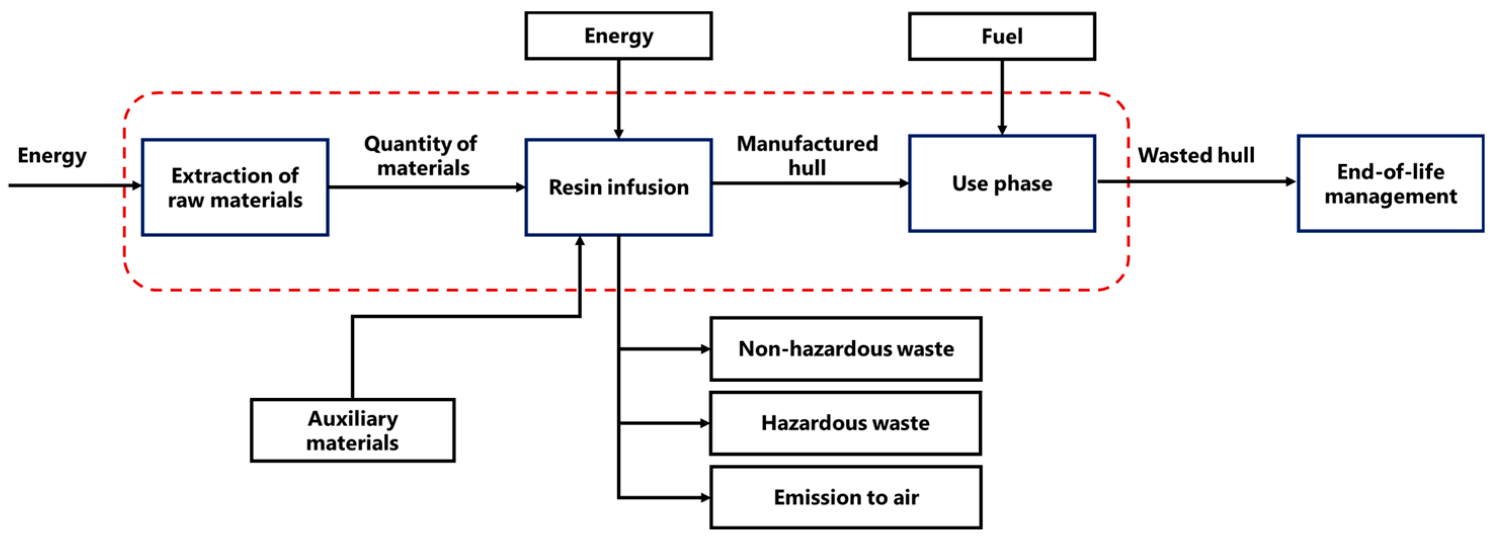
For this analysis, the cradle-to-grave approach was chosen, but the end-of-life treatment of the product was excluded. The boundaries of the analysis are illustrated in Figure 2. As a matter of fact, the focus is the evaluation of the impacts related to all stages of the product’s life cycle, from the extraction of raw materials to the use phase until the end of its useful life.

2.1.2. Life Cycle Inventory

The following materials were chosen for the construction of the GFRP hull: an E-glass fiber mat with an areal density of 600 g/m2 and CRYSTIC PD9551 polyester resin with a density of 1100 kg/m3, suitable for use in infusion processes, both chosen from a catalog [20]. The calculation of the fiber and resin masses needed to construct the hull requires the definition of volume fractions. The volume fraction value for the fiber chosen in this case, based on the works of Ahmad et al. [21] and Oh et al. [22], is 35%, which falls within the range of optimal values for the construction of structural composites such as hulls and ensures that the structural requirements of the application are met. Lopez-Arraiza et al. [18] considered a thickness of 10 mm for the fiberglass structure in their work, based on ISO 12215-5, i.e., the standard concerning hull construction and scantlings for monohull small craft [23]. This analysis considers this thickness too, from which the total volume of composite needed to build the hull is equal to 0.31 m3. Calculations were then performed to figure out the masses needed for the process in terms of the product of the volume fraction, the total volume of the composite needed, and the density of each material, as represented by Equation (1), as follows:
m i = Φ i × V t o t ρ i .
Using Equation (1), the fiber mass was calculated to be 276.7 kg and the resin mass to be 221.7 kg.
To model the raw material extraction phase, the embodied energy associated with the fiber and resin used was defined. Specifically, for glass fiber, an embodied energy of 29.9 MJ/kg was considered, as defined by the IDEMAT database, while for resin, a value of 79.2 MJ/kg was considered, as defined in the literature [24].
As for the data relating to the infusion process, the values provided by the EuCiA Eco Impact Calculator tool (European Composites Industry Association) [25] are considered, through which the unit values (per kg of finished product) of the inputs and outputs of the resin infusion process are defined, as shown in Table 3.
During the use phase, the vessel works using an internal combustion engine as defined in the assumptions. Specifically, it was assumed that a 10 HP Honda BF10 outboard motor [26] would be used, with an estimated hourly consumption of around 3.7 L/h at maximum power [27]. Therefore, considering the useful life of the boat to be 12,500 h, the total petrol consumption over its entire useful life is 46,250 L. Table 4 shows all the inputs and outputs of the system and the source of all the data used for this analysis.
The auxiliary materials entering the system include the equipment necessary for the infusion process, the protective gelcoat with which the finished hull is covered, and the release wax used to easily remove the hull from the mold. These are materials that, as initially assumed, are the same for both hulls produced.
As regards the composite hull made using a sandwich structure, the materials used are: E-glass mat fiberglass with a density of 600 g/m2 supplied by a manufactory [20], Elium 188 XO acrylic thermoplastic resin with a density of 1010 kg/m3 supplied by ARKEMA [28], and an AIREX T92 PET foam core with a density of 100 kg/m3 [29].
Compared to the previous case, the optimal thickness for the composite hull with a sandwich structure is greater, and in this analysis, based on an article published by Mario Quaresimin of the University of Padua [30], a thickness of 25 mm is chosen so that the total volume to be occupied by the composite material is 0.775 m3. According to data provided in the literature [31] concerning the use of acrylic resins for the production of glass fiber composites and assessments carried out by ARKEMA [32], it was found that the mass percentages of the material to be used are 54.4% fiber, 25.6% resin and 20% core, corresponding to volume fractions of 8.6% for fiber, 10.4% for resin and 81% for the core, which were used to calculate the masses of material required for production. Using Equation (1), the fiber mass equals 170.2 kg, the resin mass equals 80.62 kg and the foam core mass equals 62.8 kg.
In this case, too, the modeling of the raw material extraction phase considers the embodied energy associated with the materials used. The data were provided by the IDEMAT database, and the value was 29.9 MJ/kg for fiberglass, while a typical value for acrylic resins of 94.7 MJ/kg was chosen, and for the PET foam core, the value considered is 71.2 MJ/kg.
Again, the values relating to the infusion process were taken from EuCiA and are defined in Table 5.
In this case, thanks to the use of thermoplastic resin, there are no VOCs or styrene emissions.
Regarding the use phase, the same engine as in the previous case operates with a proportional relationship between mass and hourly consumption. The proportionality coefficient was calculated by considering the percentage variation between the two masses, which is equal to 0.36. This coefficient k depends on multiple factors related to the shape of the hull and, therefore, to the resistance coefficient and engine efficiency. These values are not tabulated but should be evaluated experimentally. Fuel consumption in the operational phase was estimated under identical navigation conditions, operating profile, propulsion efficiency, and cruising speed for both hulls. The reduction in fuel consumption was considered proportional to the reduction in hull mass. This simplified comparison allows the analysis to focus on the comparison of the impacts of the two constructive strategies during the use phase.
Therefore, considering this proportionality factor, the hourly consumption in this case is reduced to 2.4 L/h, so the fuel consumption over the entire useful life of the boat is equal to 30,000 L.
Table 6 shows the inputs and outputs of the system analyzed.

2.1.3. Impact Assessment

Impact analysis was conducted using Open LCA software and the CML-IA baseline impact calculation method (Centrum voor Milieuwetenschappen Leiden–Impact Assessment baseline), a scientifically recognized tool for measuring and showing environmental impacts in sustainability projects and life cycle assessments. In addition, the cumulative energy demand (CED) was also assessed, which provides a quantitative estimate of the energy required to produce, use, and dispose of an object or system, considering all stages of the life cycle enclosed within the system’s boundaries.

3. Results and Discussion

This section will analyze and discuss the results obtained using Open LCA software about the impacts associated with the hull life cycle stages considered in this study.
Table 7 summarizes the impact categories assessed and their respective quantitative values, as well as the percentage variations between the two cases analyzed.
The results of the impact analysis show that for all impact categories, there is a reduction in the respective indicators when considering the hull made using a composite sandwich structure compared to the traditional GFRP alternative. This result is mainly attributable to the greater structural efficiency of the sandwich configuration, which allows the same mechanical performance to be achieved with a smaller amount of structural composite material. In particular, the presence of the low-density PET foam core increases flexural stiffness while keeping the composite skins separate and significantly reducing the use of glass fibers and the polymer matrix, the production of which is one of the main sources of environmental impact in the life cycle of composites, as in this case. The decrease in the quantity of these materials therefore leads to a reduction in the consumption of mineral resources and fossil fuels, with positive effects on abiotic depletion, which represents the consumption of non-renewable mineral resources, and abiotic depletion linked to fossil fuels, which quantifies the consumption of fossil fuels, as well as a reduction in emissions associated with energy-intensive industrial processes, with a consequent decrease in the impacts related to global warming (GWP100a), i.e., the contribution of greenhouse gas emissions to climate change over a 100-year time horizon, and acidification associated with the emissions of acidifying compounds such as sulphur and nitrogen oxides. Similarly, the lower production of polymeric materials and fibers reduces the emissions of nitrogen and phosphate compounds responsible for eutrophication, as well as the release of potentially toxic chemicals along the production chain, leading to a decrease in the impact categories of human toxicity, freshwater aquatic ecotoxicity, marine aquatic ecotoxicity and terrestrial ecotoxicity, which assess the potential toxic impact of released substances on aquatic and terrestrial ecosystems and human health. Finally, the reduction in the emissions of volatile organic compounds and other substances generated in the extraction processes of fiber and matrix materials also leads to an improvement in the categories of photochemical oxidation associated with the formation of photochemical smog mainly due to the emissions of these compounds and ozone layer depletion (ODP), associated with the potential for the destruction of the stratospheric ozone layer.
Among the various categories of environmental impact analyzed, the most significant is that linked to global warming. For this reason, it is also assessed for each stage of the life cycle of both hulls produced, to analyze which stage of the product’s life cycle has the greatest impact in terms of CO2 emissions.
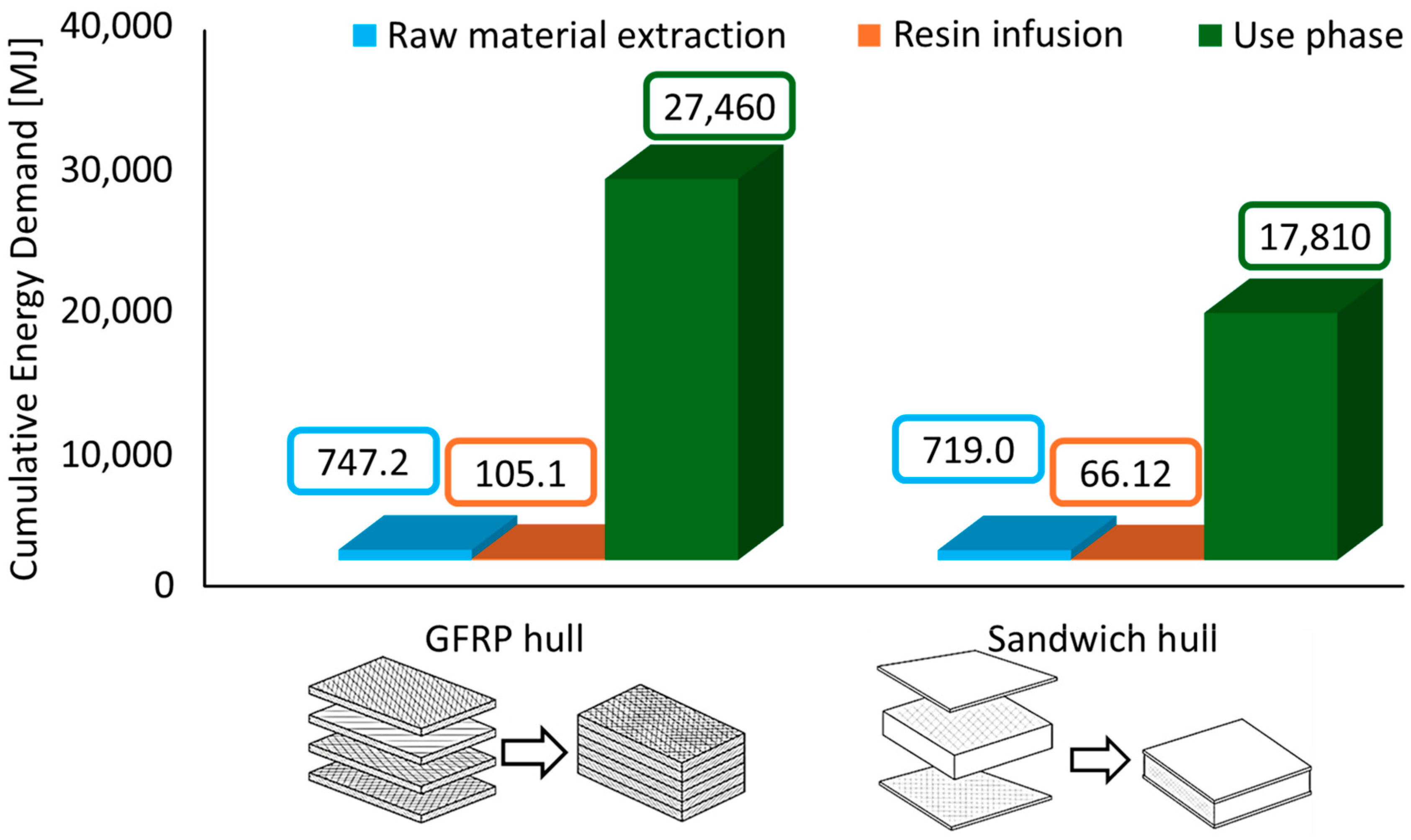
Figure 3 illustrates data on the cumulative energy demand for both cases.
As shown in the graph, the energy needed to complete the life cycle of a hull built based on a composite sandwich is reduced by 36% compared to that required for a hull built from fiberglass.

Cost Analysis

Table 8 summarizes the analysis of energy costs associated with the two solutions analyzed (unit costs refer to October 2025).
The unit costs associated with the use of traditional energy sources such as oil, electricity, and natural gas were obtained from ARERA (the Italian Regulatory Authority for Energy, Networks and Environment) [33], while the unit cost of biomass was determined based on the value reported in April 2025 [34]. The phase associated with the highest cost is the use phase, followed by the extraction of raw materials and finally the infusion process. The total energy cost associated with the life cycle of the sandwich composite hull is reduced by 35% compared to that associated with the life cycle of the GFRP hull. In addition, Table 9 reports the raw material purchase costs, in which the unit costs of the materials were extracted from the manufacturer [20] for E-glass fiber, polyester resin and the PET foam core, while the cost of thermoplastic resin was not disclosed by the manufacturer and was therefore estimated on the basis of the average costs of other similar acrylic resins on the market.
The purchase cost of the raw materials needed to produce the composite sandwich hull is 9% lower than that of the GFRP hull.

4. Conclusions

In this study, a comparative environmental analysis is conducted using OpenLCA software and data from the IDEMA and ELCD databases and the scientific literature, demonstrating that adopting a composite sandwich structure with a thermoplastic matrix is a more sustainable alternative to traditional GFRP (thermoset) construction. The key findings are summarized below:
  • Across all impact categories considered, from global warming potential to cumulative energy demand, the thermoplastic sandwich hull shows an average reduction in environmental impact of approximately 36%, with the most significant improvement observed in the raw material use and extraction phases. This overall reduction in impact is primarily attributable to the sandwich configuration’s greater structural efficiency. Indeed, the introduction of a low-density PET foam core increases flexural stiffness while keeping the composite skin separate and significantly reducing the amount of structural material required.
  • The production of glass fibers and polymer resins represents one of the system’s main environmental critical points, due to the high energy consumption and emissions associated with their extraction. Consequently, reducing the use of these materials in the sandwich hull reduces resource consumption, climate-altering emissions, and the release of potentially toxic substances along the production chain, resulting in an overall improvement in all impact categories analyzed.
  • The overall reduction in the structure’s weight leads to a reduction in fuel consumption and therefore related emissions over the vessel’s lifespan.
  • Another benefit to consider is the economic one, as the analysis shows a 35% reduction in the cost of energy required during the life cycle phases analyzed and a 9% reduction (from 5513€ to 5013€) in the purchase of raw materials.
The advantages of thermoplastic composites extend beyond their performance and energy efficiency. A key advantage lies in their recyclability potential: unlike thermoset-based glass fiber, thermoplastic matrices can offer a path toward more circular end-of-life management. Although landfill disposal currently represents the most realistic end-of-life scenario for both types of material due to the lack of an established recycling infrastructure, the use of thermoplastics offers promising opportunities for developing efficient, sustainable recycling processes that recover material value and minimize environmental impact. This study highlights that, despite existing technological and economic barriers, the transition to thermoplastic sandwich composites offers significant prospects for reducing the environmental footprint, improving material circularity, and guiding the nautical industry toward a more sustainable, resource-efficient production model. Future research will aim to extend this analysis to the end-of-life phase to assess the potential economic and environmental sustainability benefits across the entire life cycle and to include a sensitivity analysis based on a primary data inventory.

Author Contributions

Conceptualization, P.D.S. and F.T.; methodology, P.D.S. and A.A.; software, P.D.S. and A.A.; formal analysis, V.R.; investigation, V.R. and P.D.S.; resources, V.E., F.T. and A.A.; data curation, V.R. and P.D.S.; writing—original draft preparation, V.R. and P.D.S.; writing—review and editing, V.E. and F.T.; visualization, P.D.S., V.E. and F.T.; supervision, F.T. and V.E. All authors have read and agreed to the published version of the manuscript.

Funding

This research received no external funding.

Data Availability Statement

The original contributions presented in this study are included in the article. Further inquiries can be directed to the corresponding author.

Conflicts of Interest

The authors declare no conflict of interest.

References

  1. Guinée, J.B.; Heijungs, R.; Huppes, G.; Zamagni, A.; Masoni, P.; Buonamici, R.; Ekvall, T.; Rydberg, T. Life Cycle Assessment: Past, Present, and Future. Environ. Sci. Technol. 2011, 45, 90–96. [Google Scholar] [CrossRef] [PubMed]
  2. Hellweg, S.; Milà i Canals, L. Emerging Approaches, Challenges and Opportunities in Life Cycle Assessment. Science 2014, 344, 1109–1113. [Google Scholar] [CrossRef] [PubMed]
  3. Mingione, E.; Marconi, M.; Rubino, G.; Salvi, D. Reduction of Energy Consumption and Environmental Impact in Ceramic Sanitary Ware Production through Fluxing Agents: A Case Study. Int. J. Adv. Manuf. Technol. 2025, 139, 2671–2686. [Google Scholar] [CrossRef]
  4. Finnveden, G.; Hauschild, M.Z.; Ekvall, T.; Guinée, J.; Heijungs, R.; Hellweg, S.; Koehler, A.; Pennington, D.; Suh, S. Recent Developments in Life Cycle Assessment. J. Environ. Manag. 2009, 91, 1–21. [Google Scholar] [CrossRef] [PubMed]
  5. European Green Deal: Commission Aims for Zero Pollution in Air, Water and Soil. Available online: https://ec.europa.eu/commission/presscorner/detail/en/ip_21_2345 (accessed on 1 April 2026).
  6. Rigenerazione Ambientale Del Green Deal Europeo. Available online: https://www.ecomondo.com/it/dettaglio-news/rigenerazione-ambientale-del-green-deal-europeo?newsId=542723 (accessed on 10 April 2026).
  7. Nautica, C.; Edison, F. Trend Di Mercato 2024/2025; La Nautica in Cifre-Monitor; Ufficio Studi Confindustria Nautica: Genova, Italy, 2025. [Google Scholar]
  8. European Boating Industry (EBI). A Roadmap on the Implementation of the Circular Economy for End-of-Life Recreational Boats; European Boating Industry: Brussels, Belgium, 2023. [Google Scholar]
  9. Islami, D.P.; Muzaqih, A.F.; Adiputra, R.; Prabowo, A.R.; Firdaus, N.; Ehlers, S.; Braun, M.; Jurkovič, M.; Smaradhana, D.F.; Carvalho, H. Structural Design Parameters of Laminated Composites for Marine Applications: Milestone Study and Extended Review on Current Technology and Engineering. Results Eng. 2024, 24, 103195. [Google Scholar] [CrossRef]
  10. Mayya, H.B.; Pai, D.; Kini, V.M.; Padmaraj, N.H. Effect of Marine Environmental Conditions on Physical and Mechanical Properties of Fiber-Reinforced Composites—A Review. J. Inst. Eng. India Ser. C 2021, 102, 843–849. [Google Scholar] [CrossRef]
  11. Barsotti, B.; Gaiotti, M.; Rizzo, C.M. Recent Industrial Developments of Marine Composites Limit States and Design Approaches on Strength. J. Mar. Sci. Appl. 2020, 19, 553–566. [Google Scholar] [CrossRef]
  12. Vizentin, G.; Vukelic, G. Degradation and Damage of Composite Materials in Marine Environment. Mater. Sci. 2020, 26, 337–342. [Google Scholar] [CrossRef]
  13. Rubino, F.; Nisticò, A.; Tucci, F.; Carlone, P. Marine Application of Fiber Reinforced Composites: A Review. J. Mar. Sci. Eng. 2020, 8, 26. [Google Scholar] [CrossRef]
  14. Campbell, F.C. Structural Composite Materials; ASM International: Materials Park, OH, USA, 2010; ISBN 978-1-62708-314-0. [Google Scholar]
  15. Marinò, A. Costruzioni Navali in Composito; University of Trieste: Trieste, Italy, 2016. [Google Scholar]
  16. ISO 14040; Environmental Management—Life Cycle Assessment—Principles and Framework. International Organization for Standardization: Geneva, Switzerland, 2020.
  17. ISO 14044; Environmental Management—Life Cycle Assessment—Requirements and Guidelines. International Organization for Standardization: Geneva, Switzerland, 2020.
  18. Lopez-Arraiza, A.; Essamari, L.; Iturrondobeitia, M.; Boullosa-Falces, D.; Justel, D. Life Cycle Assessment of Glass Fibre versus Flax Fibre Reinforced Composite Ship Hulls. Sci. Rep. 2025, 15, 16283. [Google Scholar] [CrossRef] [PubMed]
  19. Silennis. Silennis S020. Available online: https://silennis.com/ (accessed on 20 April 2026).
  20. Resine e Fibre Rinforzanti. Available online: https://www.castrocompositesshop.com/it/ (accessed on 1 October 2025).
  21. Ahmad, J.; González-Lezcano, R.A.; Majdi, A.; Ben Kahla, N.; Deifalla, A.F.; El-Shorbagy, M.A. Glass Fibers Reinforced Concrete: Overview on Mechanical, Durability and Microstructure Analysis. Materials 2022, 15, 5111. [Google Scholar] [CrossRef] [PubMed]
  22. Oh, D.; Jang, J.; Jee, J.; Kwon, Y.; Im, S.; Han, Z. Effects of Fabric Combinations on the Quality of Glass Fiber Reinforced Polymer Hull Structures. Int. J. Nav. Archit. Ocean. Eng. 2022, 14, 100462. [Google Scholar] [CrossRef]
  23. ISO 12215-5; Small Craft-Hull Construction and Scantlings—Part 5: Design Pressures for Monohulls, Design Stresses, Scantlings Determination. International Organization for Standardization: Geneva, Switzerland, 2019.
  24. Farazmandnia, N.; Ilinca, A. Recyclable Wind Turbine Blades: A Life Cycle Analysis. Materials 2025, 18, 3762. [Google Scholar] [CrossRef] [PubMed]
  25. Welcome-EuCIA Eco Impact Calculator. Available online: https://ecocalculator.eucia.eu/Account/Login?ReturnUrl=%2F (accessed on 10 October 2025).
  26. Motore Fuoribordo Honda BF 10 SHU (MCB)-Vio Nautica. Available online: https://www.vio.it/negozio/motori-fuoribordo/motore-fuoribordo-honda-bf10-da-10-cv-shu-mcb-manuale-corto-a-barra/ (accessed on 15 April 2026).
  27. Consumi Fuoribordo Honda BF 40-50-75-90-135-150-225-250 CV|Portatile 2.3-5-8-9.9-15-20 Cv|Litri All’ora 4 Tempi. Available online: https://www.boat-fuel-economy.com/consumi-fuoribordo-honda (accessed on 15 April 2026).
  28. ARKEMA ELIUM 188 XO—Technical Data Sheet. Available online: https://page.arkema.com/rs/253-HSZ-754/images/TDS-ELIUM-EN-188_X0_SA-2023.pdf (accessed on 20 April 2026).
  29. AIREX AIREX T92—Datasheet 2024. Available online: https://trident-foams.files.svdcdn.com/production/files/3A-Composites/T92/TDS-AIREX-T92-E-02.2024-1.pdf?dm=1738766002 (accessed on 20 April 2026).
  30. Quaresimin, M. Structural Design of Composite Sandwich. Via Mare-By Sea 2004, 1, 19–25. [Google Scholar]
  31. Devine, M.L. Liquid Acrylic Resin-Based Composites for Marine and Renewable Energy Applications. Ph.D. Thesis, The University of Edinburgh, Edinburgh, UK, 2024. [Google Scholar]
  32. EcovaMed-ARKEMA. Cradle-to-Grave Carbon Footprint of Elium-Based Recyclable Composites vs Epoxy-Based Composites; EcovaMed-Arkema: Paris, France, 2024. [Google Scholar]
  33. Arera: Home|ARERA. Available online: https://www.arera.it/ (accessed on 15 April 2026).
  34. Rudello, G. Prezzo Del Cippato Ad Aprile 2025. Available online: https://energiadallegno.it/prezzo-del-cippato-ad-aprile-2025/ (accessed on 15 April 2026).
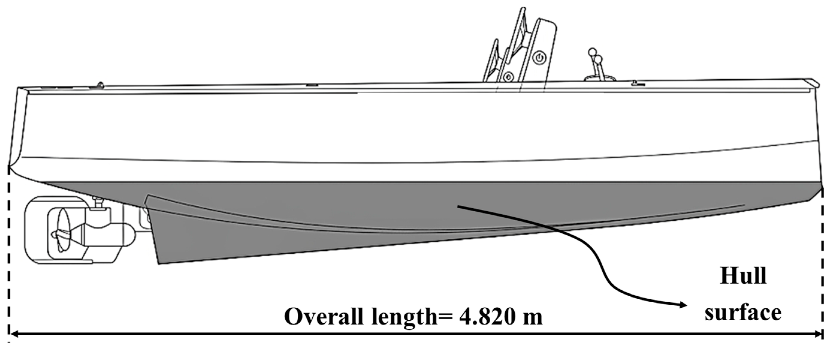
Figure 1. Schematic illustration of functional unit.
Jmmp 10 00192 g001
Figure 2. System boundaries (in red dashed lines): Cradle-to-grave approach excluding end-of-life treatment.
Jmmp 10 00192 g002
Figure 3. Comparison of cumulative energy demands (CEDs) for GFRP and sandwich hulls.
Jmmp 10 00192 g003
Table 1. Efficiency of sandwich structure [14].
Solid MaterialSandwich ConstructionThicker Sandwich
Thicknesst2t4t
Stiffness1.07.037.0
Flexural Strength1.03.59.2
Weight1.01.031.06
Table 2. Properties of functional unit [19].
PropertyValueUnit
Overall length4.820m
Hull surface31m2
Beam of the hull1.850m
Draft of the fully loaded waterline0.525m
Fully loaded displacement mass872kg
Table 3. Resin infusion inputs and outputs for GFRP hull manufacturing (per kg of finished product) [25].
InputAmountUnit
Electricity3.96 × 10−1kWh/kg
Water2.25 × 10−4m3
Natural gas1.95 × 10−2m3
OutputAmountUnit
Non-hazardous waste1.60 × 10−1kg
Hazardous waste1.76 × 10−2kg
VOCs6.27 × 10−3kg
Styrene5.84 × 10−3kg
Table 4. Inputs and outputs of GFRP hull life cycle inventory.
FlowQuantityUnitData SourceProvider
Extraction of raw materialsInputs
Energy required for E-glass fiber extraction8273MJCalculated from literature dataGlass fiber—dry and chopped—for reinforcing plastics (IDEMAT database + literature data)
Energy required for unsaturated polyester resin extraction17,559MJCalculated from literature dataPolyester (unsaturated resin) (IDEMAT database + literature data)
Outputs
E-glass fiber276.7kgCalculated from literature dataGlass fiber—dry and chopped—for reinforcing plastics (IDEMAT database)
Unsaturated polyester resin221.7kgCalculated from literature dataPolyester (unsaturated resin) (IDEMAT database + literature data)
Resin infusionInputs
E-glass fiber276.7kgCalculated from literature dataGlass fiber—dry and chopped—for reinforcing plastics (IDEMAT database)
Unsaturated polyester resin221.7kgCalculated from literature dataPolyester (unsaturated resin) (IDEMAT database + literature data)
Electricity710.6MJEuCiaElectricity grid mix 1 kV–60 kV, consumption mix, at consumer, AC, 1 kV–60 kV (ELCD database)
Natural gas9.72m3EuCiaNatural Gas Mix, consumption mix, at consumer, technology mix, onshore and offshore production incl. pipeline and LNG transport (ELCD database)
Water0.11m3EuCiaProcess water, production mix, at plant, ion exchange, from groundwater (ELCD database)
Release wax0.04kgAssessed based on the size of the hullAuxiliary materials
Gelcoat17.05kg
Peel-ply31m2
Sealant tape15m
Net bleeder31m2
Tubes5m
Vacuum bag31m2
Outputs
Manufactured hull420.99kg
Non-hazardous waste79.7kgEuCiaWaste flow
Hazardous waste8.77kgEuCiaWaste flow
VOCs3.12kgEuCiaEmission to air
Styrene2.91kgEuCiaEmission to air
Use phaseInputs
Manufactured hull420.99kgCalculated
Fuel46,250lCalculated from literature dataGasoline mix (regular) at refinery, production mix, at refinery, from crude oil and biocomponents, fuel supply, 10 ppm sulphur, 5.75 wt.% biocomponents (ELCD database)
Outputs
Wasted hull420.99kg End-of-life management
Table 5. Resin infusion inputs and outputs for sandwich hull manufacturing (per kg of finished product) [25].
InputAmountUnit
Electricity3.96 × 10−1kWh/kg
Water2.25 × 10−4m3
Natural gas1.95 × 10−2m3
OutputAmountUnit
Non-hazardous waste1.60 × 10−1kg
Hazardous waste1.76 × 10−2kg
Table 6. Inputs and outputs of sandwich hull inventory.
FlowAmountUnitData SourceProvider
Extraction of raw materialsInputs
Energy required for E-glass fiber extraction5089MJCalculated from literature dataGlass fiber—dry and chopped—for reinforcing plastics (IDEMAT database + literature data)
Energy required for thermoplastic resin extraction7633MJCalculated from literature dataPMMA (Polymethyl methacrylate) (IDEMAT database)
Energy required for PET foam extraction4472MJCalculated from literature dataPET (Polyethylene terephthalate) amorphous (IDEMAT database)
Outputs
E-glass fiber170.2kgCalculated from literature dataGlass fiber—dry and chopped—for reinforcing plastics (IDEMAT database + literature data)
Thermoplastic acrylic resin80.6kgCalculated from literature dataPMMA (Polymethyl methacrylate) (IDEMAT database)
PET foam core62.8kgCalculated from literature dataPET (Polyethylene terephthalate) amorphous (IDEMAT database)
Resin infusionInputs
E-glass fiber170.2kgCalculated from literature dataGlass fiber—dry and chopped—for reinforcing plastics (IDEMAT database + literature data)
Thermoplastic acrylic resin80.6kgCalculated from literature dataPMMA (Polymethyl methacrylate) (IDEMAT database)
PET foam core62.8kgCalculated from literature dataPET (Polyethylene terephthalate) amorphous (IDEMAT database)
Electricity447.1MJEuCiaElectricity grid mix 1 kV–60 kV, consumption mix, at consumer, AC, 1 kV–60 kV (ELCD database)
Natural gas6.12m3EuCiaNatural Gas Mix, consumption mix, at consumer, technology mix, onshore and offshore production incl. pipeline and LNG transport (ELECD database)
Water0.071m3EuCiaProcess water, production mix, at plant, ion exchange, from groundwater (ELCD database)
Release wax0.04kgAssessed based on the hull sizeAuxiliary materials
Gelcoat17.05kg
Peel-ply31m2
Sealant tape15m
Net bleeder31m2
Tubes5m
Vacuum bag31m2
Outputs
Manufactured hull274.97kgCalculated
Non-hazardous waste50.2kgEuCiaWaste flow
Hazardous waste5.52kgEuCiaWaste flow
Use phaseInputs
Manufactured hull274.97kgCalculated
Fuel30,000LCalculated from literature dataGasoline mix (regular) at refinery, production mix, at refinery, from crude oil and biocomponents, fuel supply, 10 ppm sulphur, 5.75 wt.% biocomponents (ELCD database)
Outputs
Wasted hull274.97kg End-of-life management
Table 7. Impact categories and quantitative values of them associated with GFRP and sandwich hull.
Impact CategoriesUnitGFRP HullSandwich Hull% Reduction
Abiotic depletionkg Sb eq1.21 × 10−57.93 × 10−634.6
Abiotic depletion (fossil fuels)MJ1.79 × 1061.15 × 10635.6
Acidificationkg SO2 eq1.54 × 1021.00 × 10234.6
Eutrophicationkg PO4 eq9.92 × 1006.47 × 10034.7
Fresh water aquatic ecotoxicitykg 1.4-DB eq7.63 × 1014.24 × 10144.4
Global warming (GWP100a)kg CO2 eq2.82 × 1041.86 × 10434.1
Human toxicitykg 1.4-DB eq1.35 × 1038.76 × 10235.1
Marine aquatic ecotoxicitykg 1.4-DB eq8.63 × 1055.59 × 10535.3
Ozone layer depletion (ODP)kg CFC-11 eq6.56 × 10−54.25 × 10−535.2
Photochemical oxidationkg C2H4 eq1.23 × 1018.14 × 10033.8
Terrestrial ecotoxicitykg 1.4-DB eq1.19 × 1018.06 × 10032.1
Table 8. Impact categories and quantitative values.
PhaseEnergy
Source
AmountUnitUnit Cost [€/unit]Total Cost [€]
Raw material extraction
GFRPE-glass fiberNatural gas8273MJ0.00988255.2
Polyester resinNatural gas17,559MJ0.00988
SandwichE-glass fiberNatural gas5089MJ0.00988169.3
Thermoplastic resinNatural gas7633MJ0.00988
PET foam coreBiomass100.5MJ0.00917
Petrol2142MJ0.00965
Natural gas2230MJ0.00988
Resin infusion
GFRP Electricity710.6MJ0.06952.7
Natural gas9.72m30.3734
Sandwich Electricity447.1MJ0.06933.1
Natural gas6.12m30.3734
Use phase
GFRP Fuel46,250L1.7580,938
Sandwich Fuel30,000L1.7552,500
Table 9. Raw material purchase costs.
Raw MaterialAmount [kg]Unit Cost [€/kg]Total Cost [€]
GFRP hullE-glass fiber276.75.51521.9
Polyester resin221.7183990.6
Total 1 5513 1
Sandwich hullE-glass fiber170.25.5936.1
Thermoplastic resin80.6352821
PET foam core62.8201256
Total 1 5013 1
1 Totals are reported in bold characters.
Disclaimer/Publisher’s Note: The statements, opinions and data contained in all publications are solely those of the individual author(s) and contributor(s) and not of MDPI and/or the editor(s). MDPI and/or the editor(s) disclaim responsibility for any injury to people or property resulting from any ideas, methods, instructions or products referred to in the content.