1. Introduction
Robotic milling enables machining of large components with greater reconfigurability and lower capital cost than conventional CNC machine tools. However, despite an estimated 4.3 million industrial robots in operation worldwide, only about 1.5% are used in machining applications [
1], with an even smaller fraction employed for milling. This limited adoption is primarily due to the low and configuration-dependent stiffness of serial kinematic robots, which constrains dynamic stability and machining accuracy.
Milling robots are serial kinematic systems with open-chain architectures, leading to tool-point stiffness up to two orders of magnitude lower than that of conventional machine tools [
2,
3,
4,
5]. The low-frequency global structural modes of the robot are significantly more compliant than higher-frequency spindle–tool–holder modes, resulting in strongly pose-dependent dynamics. This configuration-dependent compliance—primarily arising from robot joints—governs vibration response, chatter stability, and machining accuracy [
6,
7,
8,
9].
Self-excited vibrations in robotic milling have been traditionally interpreted using regenerative and mode-coupling mechanisms. High-frequency instabilities are commonly attributed to regenerative effects [
7], while mode-coupling has been proposed to explain low-frequency behavior [
10]. However, these models do not fully capture the observed dynamics in robotic milling, particularly under intermittent cutting conditions, where additional mechanisms beyond classical regenerative and mode-coupling effects become significant [
11]. Recent work shows that low-frequency chatter in robotic milling is driven by modulation effects arising from time-varying tool–workpiece engagement. Xin et al. [
12] demonstrate that classical models fail to capture this behavior, as they neglect modulated chip thickness. The resulting interaction between structural modes and periodic excitation produces sideband frequencies, indicating that robotic milling dynamics are inherently non-stationary and modulation-driven.
Given that chatter degrades machining quality and productivity [
2,
3,
4], extensive research has focused on improving stability in robotic milling. Robot posture has been identified as a primary factor governing dynamic behavior. Guo et al. [
13] showed that stiffness-oriented posture optimization improves machining performance by selecting configurations with higher directional stiffness. Chen et al. [
14] demonstrated that tool-point frequency response functions vary strongly with posture, enabling prediction of configuration-dependent dynamics. Celikag et al. [
15] and Mousavi et al. [
16] further showed that chatter stability can be enhanced by selecting favorable configurations or exploiting kinematic redundancies to control configuration-dependent dynamics. Vosniakos and Matsas [
17] demonstrated that appropriate robot placement can improve machining feasibility by avoiding highly compliant configurations.
Complementary to posture selection, workpiece placement also influences robotic milling performance by determining feasible robot configurations during machining. Qin et al. [
18] showed that optimizing workpiece pose improves quasi-static stiffness in flexible-joint robots, while Li et al. [
19] demonstrated that workpiece clamping position and cutter path affect stability by altering the effective configuration and force direction. These studies establish that robot posture and workpiece placement jointly govern vibration and stability through configuration-dependent stiffness.
Additional approaches include grey-box modeling frameworks that combine physics-based robot dynamics with data-driven friction modeling to predict path deviations [
20], as well as active and passive vibration suppression strategies to enhance dynamic stiffness and reduce vibrations [
21,
22].
In addition to pose-dependent compliance, feed direction and cutting orientation play a critical role in governing stability and vibration behavior in robotic milling. Tunc and Shaw [
23] showed that stability depends strongly on configuration-dependent structural dynamics, leading to directional variation in stability limits. Tunc and Stoddart [
24] demonstrated that aligning feed direction with stiffer robot directions increases chatter-free material removal rates. Gonul et al. [
25] showed that kinematic redundancy can be exploited to identify configurations with improved stability. More recently, Dombovari et al. [
26] identified the directional factor as a key parameter governing chatter, emphasizing the importance of excitation–structure alignment. Together, these studies show that cutting direction directly influences chatter onset and vibration response through anisotropic structural compliance.
In parallel, studies in multi-axis CNC milling show that tool orientation influences cutting forces and surface roughness, with certain inclinations improving machining performance [
27,
28]. However, these studies focus on geometric and kinematic effects in conventional machine tools and do not account for the interaction between structural compliance and cutting dynamics in robotic systems.
Despite increasing recognition of pose-dependent compliance and directional effects, the dynamic behavior of robotic milling under simultaneous variations in tool-path strategy, cutting orientation, and robot pose remains incompletely understood, particularly in terms of how low-frequency compliance influences operational vibration characteristics and machining outcomes. Prior studies have largely examined these factors in isolation, with limited benchmarking against conventional CNC machining under matched conditions. Moreover, the role of modulation-driven dynamics in shaping vibration behavior and machining accuracy has received limited experimental attention.
The primary contributions of this work are as follows. First, a controlled experimental framework is developed to isolate the coupled effects of robot pose, cutting orientation, spindle speed, and depth of cut on dynamic response, enabling direct comparison with a conventional CNC system under matched conditions. Second, the study demonstrates that robotic milling dynamics are governed by low-frequency structural compliance that induces modulation of spindle-synchronous vibrations, rather than direct resonance at structural natural frequencies. This behavior is characterized using spindle-synchronized Poincaré sections, which reveal cycle-to-cycle variability not captured by conventional spectral analysis. Third, orientation-resolved polar representations establish direct links between vibration anisotropy, modulation behavior, and machining outcomes, including dimensional error and surface roughness. Finally, the results show that high-frequency tool–holder modes remain largely invariant across poses, while low-frequency global modes control modulation and performance, providing a basis for configuration-aware process planning in robotic milling.
The remainder of the paper presents the experimental methodology, followed by analysis of dynamic response and surface quality, and concludes with implications for configuration-aware robotic milling process planning.
2. Experimental Setups, Plan, and Procedures
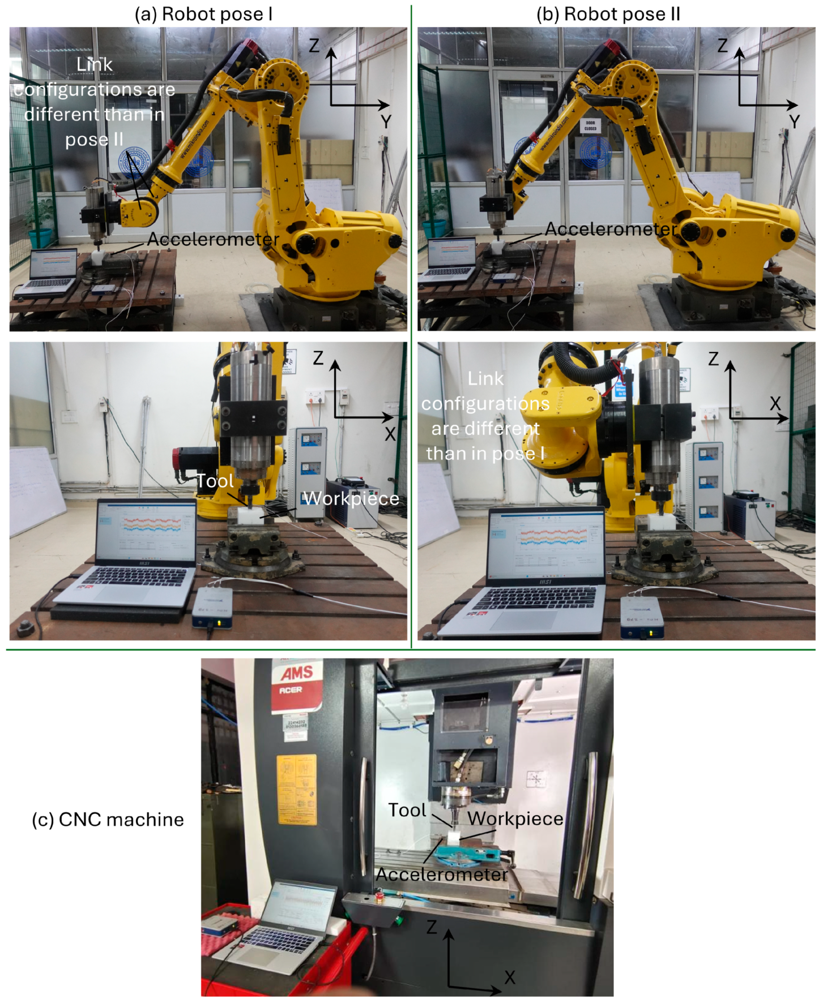
Robotic milling experiments were conducted using a FANUC S-430iW industrial robot (manufacturer: FANUC; city and country: Oshino-mura, Yamanashi Prefecture, Japan) that has a payload of 165 kg equipped with an 18,000 rpm spindle. Benchmark experiments were performed on an AMSL ACER 3-axis CNC milling machine (manufacturer: AMSL, city and country: Bangalore, India) with a 15,000 rpm spindle. The experimental setups are shown in
Figure 1. Two distinct robot poses were investigated (
Figure 1a,b), with identical tool-center-point locations but different joint configurations.
A 16 mm diameter, four-fluted solid carbide end mill (Totem XL series, EM 190818.11 (manufacturer: TOTEM, city and country: Aurangabad, India)) with a TiAlN-type coating was used for all experiments. The tool stick-out was maintained at 50 mm. Although collet holders were used in both setups, the spindle–holder interfaces differed.
The workpiece material was an acetal homopolymer (Delrin
®), selected to isolate machine-induced dynamic effects from material-related variability. See
Table 1 for its typical material properties. Its low cutting forces, homogeneous microstructure, and absence of strain hardening or built-up edge formation enable stable and repeatable cutting conditions. This is critical in the present study, as it ensures that the observed amplitude modulation and cycle-to-cycle variability are governed by pose-dependent structural compliance and excitation–structure interaction, rather than material-induced nonlinearities. Similar materials have been used in prior robotic milling studies for this purpose [
21].
Axial depths of cut () were 0.5 mm and 1 mm, spindle speeds () were 5500 rpm and 7500 rpm, and feed per tooth and radial engagement (radial depth of cut, ) were fixed at 0.1 mm/tooth and 100% (full-immersion slot milling), respectively. The selected spindle speeds were chosen to examine speed-dependent dynamic behavior, while the two levels of axial depth of cut were used to vary cutting force and energy input. The parameter range is representative of typical robotic milling conditions, where relatively low depths of cut are employed due to limited structural stiffness, ensuring both practical relevance and controlled variation in dynamic response.
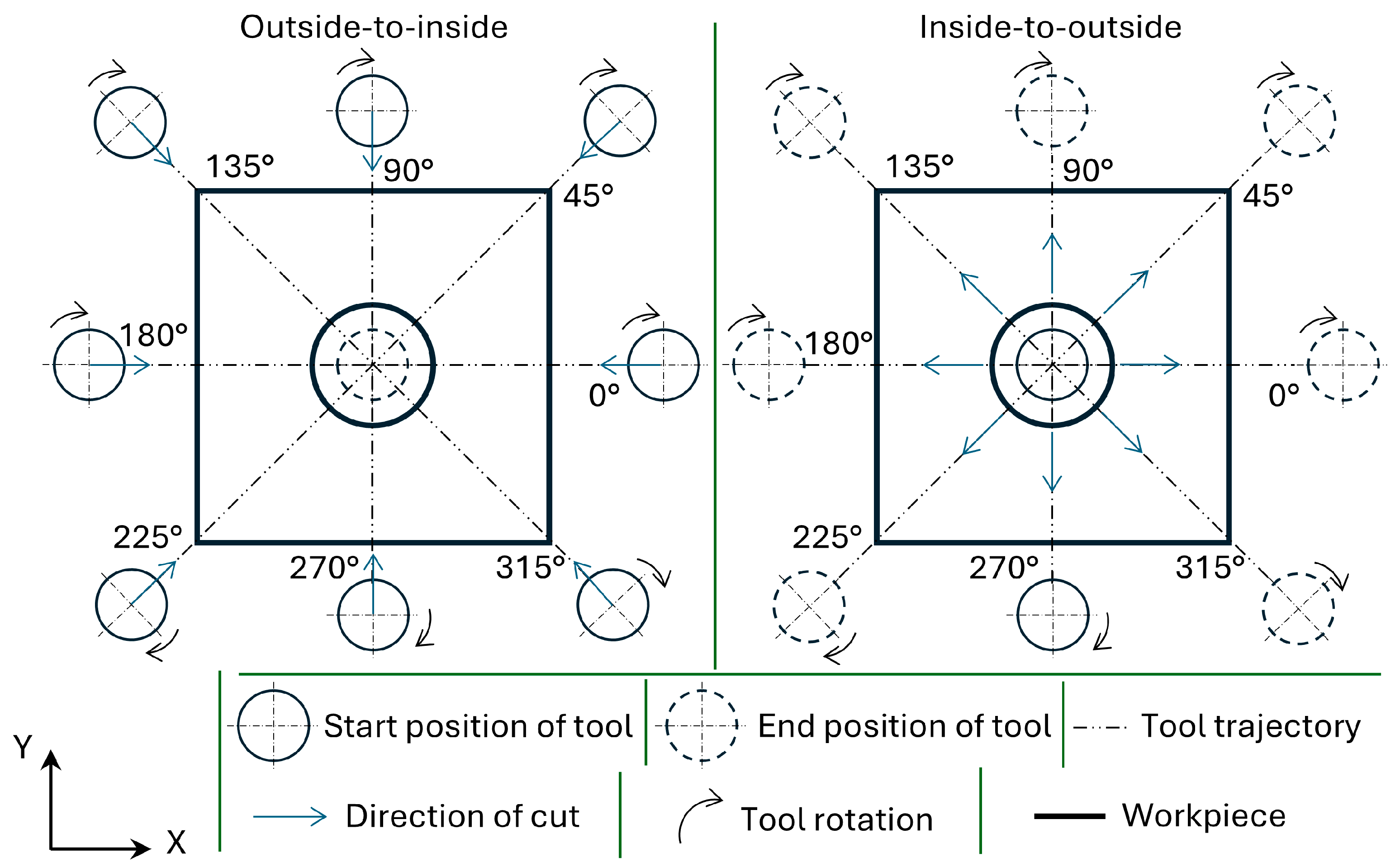
To study directional effects, cutting orientation was varied in 45° increments, resulting in eight orientations per test condition (
Figure 2). Cuts were performed using both inside-to-outside and outside-to-inside strategies. The workpiece dimensions were 80 mm × 80 mm × 100 mm, with a central 20 mm hole used for tool entry/exit. The resulting cut length varied between 30 mm and 35 mm. Each test was repeated twice, resulting in more than 768 experiments across both robot poses and the CNC system.
During cutting, tri-axial accelerations were measured using an ENDEVCO 44A16-1032 accelerometer (manufacturer: Endevco, city and country: Halifax, NC, USA) mounted near the workpiece. Signals were sampled at 25.6 kHz using an NI 9234 module in an NI 9171 chassis (manufacturer: National Instruments, city and country: Austin, TX, USA) and low-pass filtered at 2 kHz. Data acquisition and processing were performed using MATLAB Signal Analyzer (2025b) Surface roughness was evaluated using a Mahr Pocket Surf IV by averaging measurements obtained over three separate 5 mm traverse lengths along the direction of cut for each machined surface. Measurements were repeated to ensure consistency.
Tool condition was inspected during the experiments, and no noticeable flank wear or edge degradation was observed. Given the use of acetal homopolymer, a soft and low-abrasion material, tool wear effects are considered negligible and are not expected to influence the measured vibration response or surface quality.
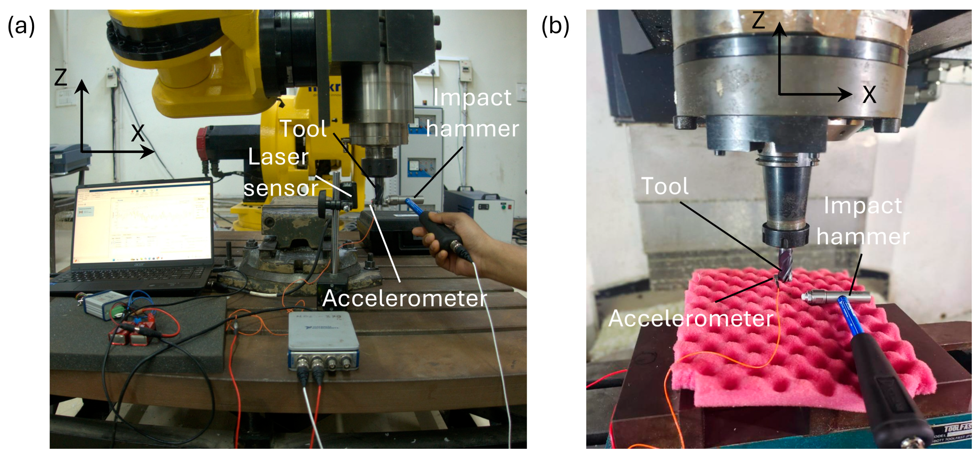
Tool-point frequency response functions (FRFs) were measured using measurement setups as shown in
Figure 3.
FRFs were obtained via impact testing using an instrumented hammer (Dytran 5800B4 (manufacturer: Dytran, city and country: Chatsworth, CA, USA)). For the robot, the response was measured using a laser displacement sensor (Micro-Epsilon ILD1420–10 901 (manufacturer: Micro-Epsilon, city and country: Ortenburg, Germany)) and a single-axis accelerometer (Dytran 3225F1 (manufacturer: Dytran, city and country: Chatsworth, CA, USA)) mounted on the tool. The displacement measurement was used to capture low-frequency response, while the acceleration signal ensured higher-frequency fidelity. The displacement and acceleration signals were sampled at 4 kHz and 25.6 kHz, respectively. For the CNC machine, only the accelerometer was used, as no significant low-frequency modes were observed. Dynamics were measured along the principal Cartesian directions (X, Y, and Z) for both robot poses.
The resulting tool-point FRFs provide a baseline characterization of system dynamics. The following section presents these results and relates them to the vibration behavior observed during cutting.
3. Dynamic Behavior of the Robot and the CNC Machine
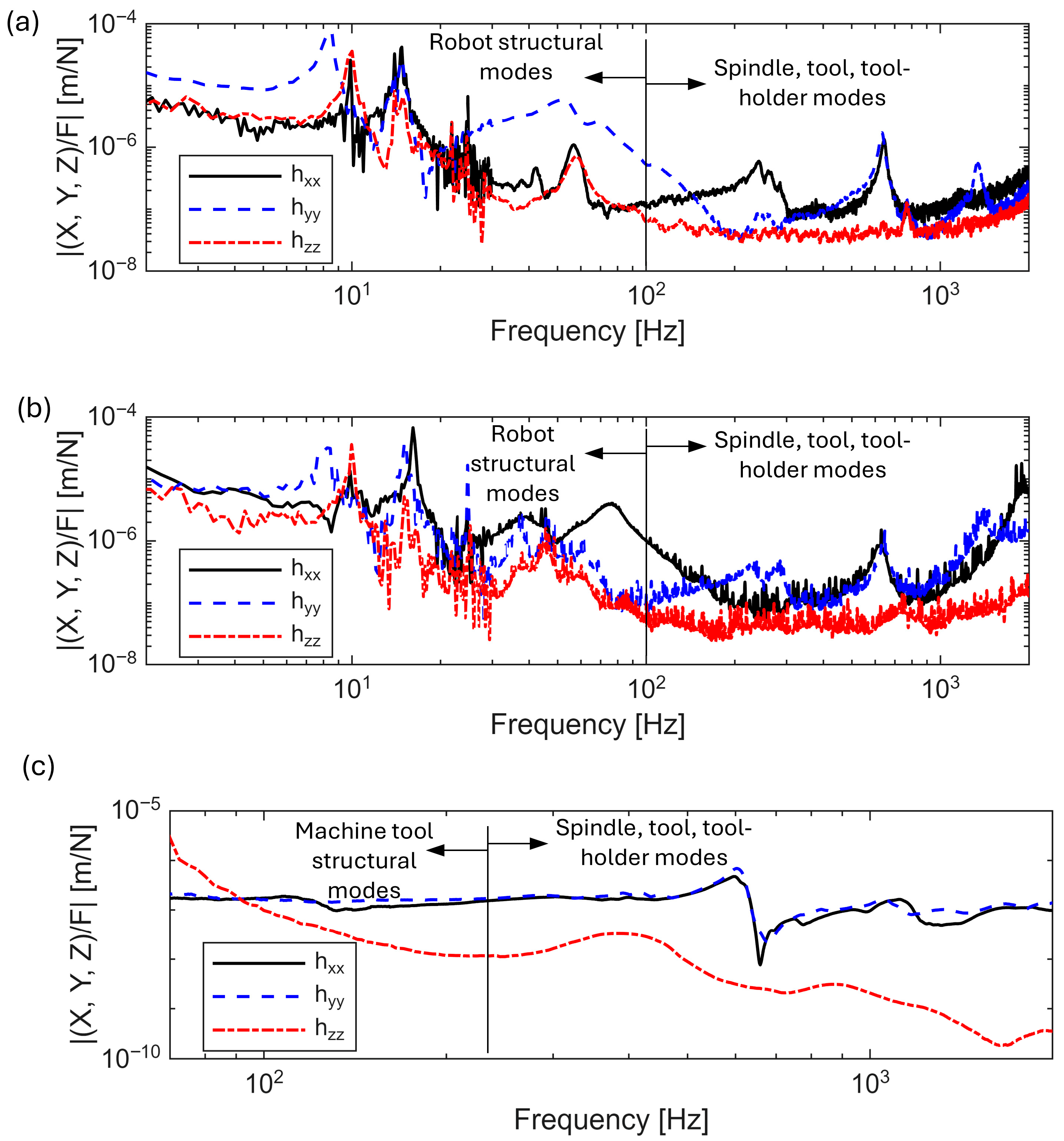
The measured tool-point dynamics, expressed as FRFs in the principal X, Y, and Z directions, are shown in
Figure 4 for both robot poses and the CNC machine tool. The FRFs were obtained by dividing the FFT of the measured response by the measured force. For the CNC machine, accelerances were converted to receptances by dividing by
, where
is the angular frequency. Peaks in the FRFs correspond to structural modes, and their magnitudes represent the associated flexibilities.
For the robot in Pose I (
Figure 4a), the dynamics are dominated by low-frequency structural modes below 20 Hz with clear directional characteristics. Prominent peaks at approximately 8 Hz (~7.2 × 10
−5 m/N), 10 Hz (~3.6 × 10
−5 m/N), and 15 Hz (~4.2 × 10
−5 m/N) occur primarily in the lateral directions (X and Y), with the Y-direction exhibiting the highest compliance and the Z-direction showing minimal participation. These modes correspond to global bending of the robot structure. At intermediate frequencies, a mode near 55 Hz (~1 × 10
−6 m/N) appears predominantly in Y, with weaker presence in X and in Z. A further mode at approximately 240 Hz (~5.8 × 10
−7 m/N) is primarily X-dominant, indicating directionally localized compliance. At higher frequencies, the response is governed by tool–tool-holder dynamics, with a prominent mode near 630 Hz (~1.7 × 10
−6 m/N) appearing in both X and Y with comparable magnitude, indicating a symmetric in-plane bending mode. Additional modes beyond 1 kHz, including a peak near 1350 Hz (~5.1 × 10
−7 m/N), are more localized and exhibit lower amplitudes. Overall, low-frequency modes dominate the response and are one to two orders of magnitude more compliant than higher-frequency modes, while the Z-direction remains comparatively stiff. The Z-direction response, particularly at higher frequencies, exhibits increased noise due to low signal levels and should be interpreted with caution.
For the robot in Pose II (
Figure 4b), the overall behavior remains similar, but with noticeable changes in directional participation and modal amplitudes. The low-frequency modes (~8–16 Hz) persist, but the response is more evenly distributed between X and Y, with reduced dominance of the Y-direction. Peak magnitudes remain on the order of 10
−5 m/N, indicating continued high compliance in this range. In the mid-frequency range, a mode near 75–80 Hz (~4 × 10
−6 m/N) appears more prominently in X than in Pose I, and modes in the 20–30 Hz range show stronger X–Y coupling, indicating increased cross-axis interaction. At higher frequencies, the tool–holder mode near 630 Hz (~1.3 × 10
−6 m/N) remains clearly visible and nearly symmetric in X and Y, confirming that it is largely insensitive to robot pose and governed by the end-effector subsystem. Across both poses, a clear separation persists between low-frequency global modes, which dominate compliance and response, and higher-frequency localized modes. Frequencies above approximately 1500 Hz should be interpreted with caution, as they approach the Nyquist limit of the 4 kHz sampling rate and exhibit reduced signal-to-noise ratio, particularly in the Z-direction.
The CNC machine tool (
Figure 4c) exhibits a markedly different dynamic response. A dominant mode is observed near 600 Hz in both X and Y directions, with a peak magnitude of approximately 2 × 10
−7 m/N, corresponding to a tool–tool-holder mode. A lower-frequency mode near 100 Hz appears in X but remains significantly stiffer than the dominant high-frequency response. The Z-direction is several orders of magnitude stiffer than the lateral directions; however, the apparent low-frequency slope in Z is influenced by sensor noise and should be interpreted cautiously. The axis limits differ from those used for the robot FRFs, reflecting the absence of significant low-frequency structural modes in the CNC system, with negligible dynamic activity below approximately 100 Hz.
Overall, the robot exhibits substantially higher dynamic compliance than the CNC machine, particularly in the low-frequency range. These FRFs establish a baseline for interpreting the modulation and vibration behavior observed during cutting in the following section.
4. Comparative Operational Dynamics of Robotic and CNC Milling
Building on the structural dynamics characterized in
Section 3, this section examines the vibration response of the robot and CNC machine during cutting. Tri-axial accelerations (X, Y, and Z) are analyzed in the time and frequency domains for each test condition. Fourier spectra are used to identify dominant excitation components and broadband amplification. Spectral peaks occur primarily at multiples of the spindle rotational frequency rather than at the nominal tooth-passing frequency, which is attributed to tool run-out in the mounted configuration. Poincaré sections, constructed by sampling once per spindle revolution, are used to examine cycle-to-cycle variability and modulation in the response. Results are compared across machine platform, pose, speed, depth of cut, and cutting orientation to clarify operational differences between CNC and robotic milling.
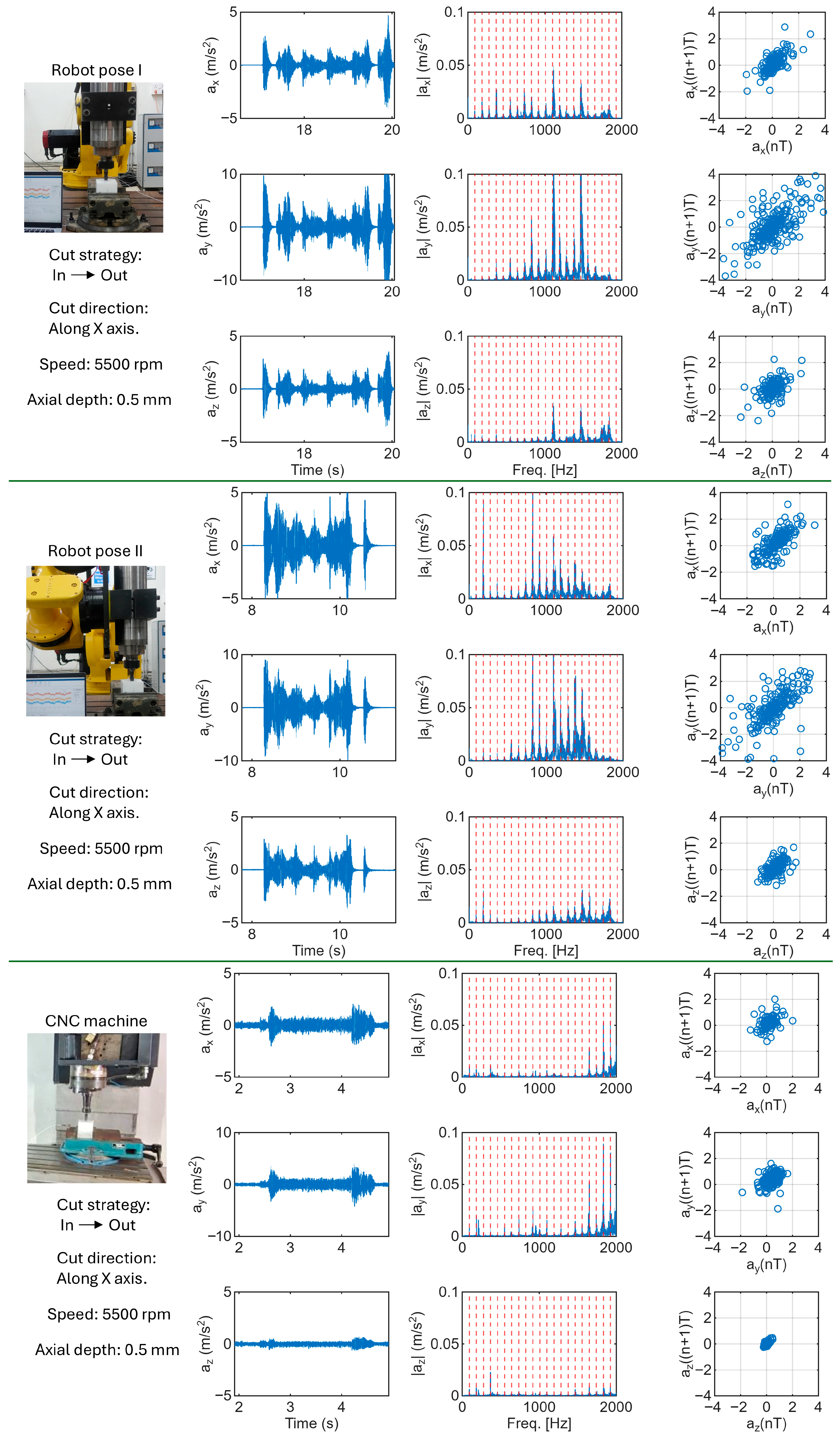
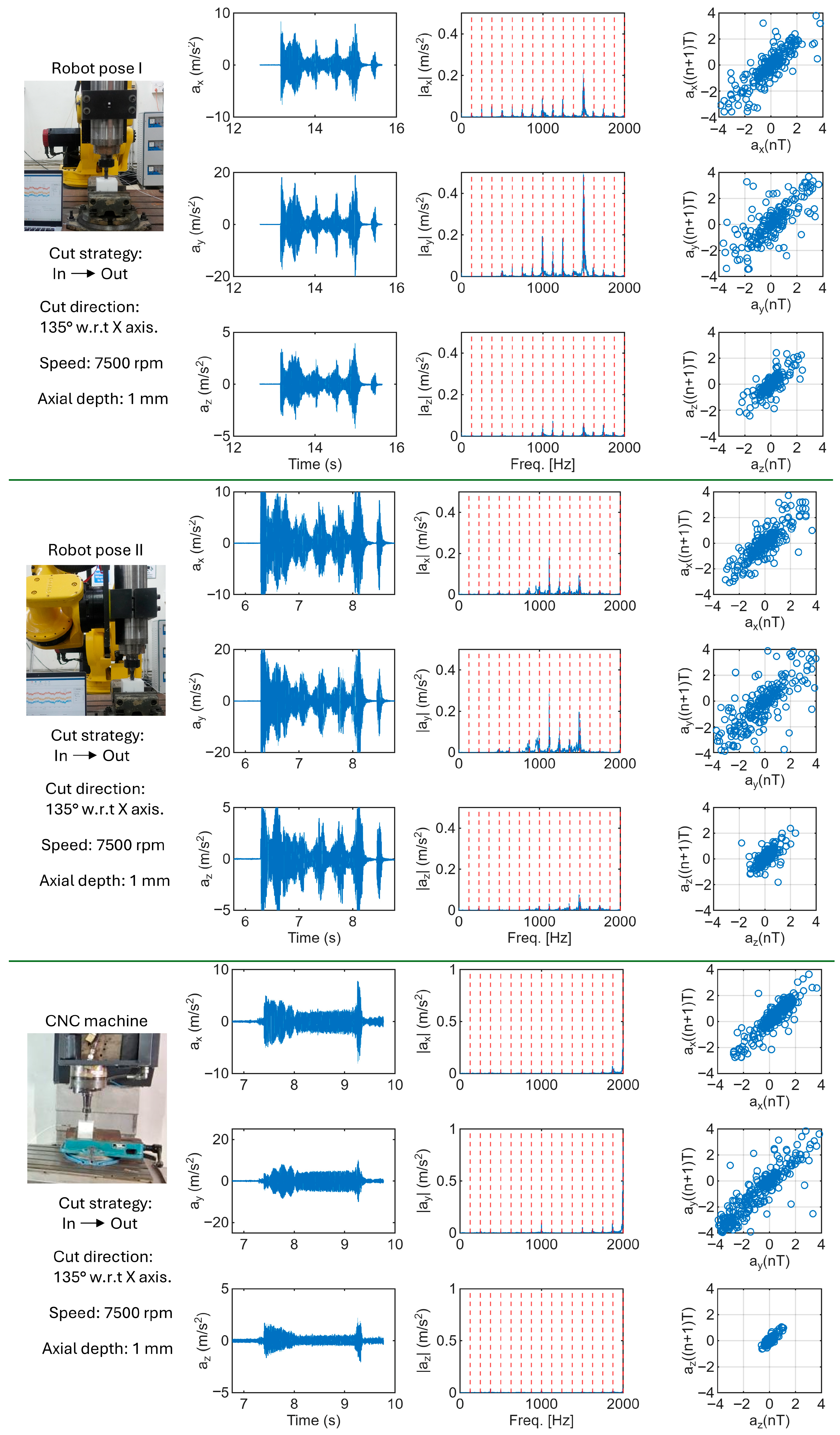
Representative responses are shown in
Figure 5 and
Figure 6. At 5500 rpm and 0.5 mm axial depth (
Figure 5), the vibration response is strongly pose-dependent. The time signals exhibit clear amplitude variations associated with tool entry into and exit from the material. These transients arise from the abrupt change in cutting force as chip load transitions from zero to steady engagement and back to disengagement. Entry produces short bursts of vibration due to rapid force buildup, whereas exit is characterized by a sudden force release followed by decay of the response. These effects are more pronounced in the robotic configurations, reflecting their lower structural stiffness and greater sensitivity to engagement dynamics.
In Pose I, the response is dominated by the in-plane components. The largest amplitudes occur in
, followed by
, while
remains comparatively small. This directional behavior is consistent with the FRF results presented earlier, which identified greater compliance in the lateral directions of the robotic structure. The time signals also exhibit a pronounced amplitude modulation superimposed on the spindle-period vibration. However, the corresponding Fourier spectra do not show a distinct modulation frequency. Instead, spectral energy is distributed across broadened spindle harmonics, indicating that the modulation arises from non-stationary or broadband dynamics rather than a single periodic excitation. Further insight is provided by the Poincaré sections in
Figure 5. A strictly periodic response would collapse to a single point when sampled once per spindle revolution. Instead, the maps form compact clusters, indicating that successive spindle revolutions are correlated but not identical. The broader distributions observed in
and
reflect cycle-to-cycle variability in the lateral vibration components, while the tighter cluster in
indicates a smaller vertical contribution to the modulation. The slow envelope modulation observed in the time signals occurs within the 2–10 Hz range, which coincides with several low-frequency structural modes of the robotic system identified in
Section 3. This correspondence suggests that the modulation arises from interaction between cutting forces and these low-frequency structural modes, producing quasi-periodic variations in vibration amplitude even though a distinct modulation peak is not visible in the conventional Fourier spectrum.
Since the dominant excitation frequencies (spindle harmonics) are much higher than the low-frequency structural modes (<20 Hz), these modes are not directly excited at resonance. Instead, the compliant structure undergoes slow deformation under cutting forces, modulating chip thickness and producing an amplitude envelope on the spindle-synchronous response.
In Pose II, the directional response shifts relative to Pose I. The component becomes more pronounced, and the contribution of increases, particularly during the high-amplitude bursts observed in the time signals, indicating stronger cross-axis coupling and greater vertical participation. The corresponding spectra exhibit broader spindle harmonics and increased broadband content compared to Pose I, consistent with a more distributed vibration response. Similar to Pose I, no spectral peaks align with the structural natural frequencies, indicating that the low-frequency modes primarily influence the response through amplitude modulation rather than direct resonance. The Poincaré sections show slightly increased dispersion in and , reflecting stronger cycle-to-cycle variability in the lateral components. As in the previous case, the clustered structure of the sections suggests quasi-periodic modulation associated with the interaction between cutting forces and the low-frequency structural modes of the robotic system.
The CNC machine shows no strong directional dominance. The in-plane components remain moderate and controlled, is minimal, and the spectra are sharply peaked at spindle harmonics with negligible sideband development. The Poincaré sections collapse to compact clusters, consistent with rotation-synchronous behavior and lower dynamic amplification than in the robotic configurations.
Figure 6 presents the corresponding vibration responses for cutting at 7500 rpm with a 1 mm axial depth and a cutting direction oriented at 135° relative to the X axis. Compared with the conditions of
Figure 5, the higher spindle speed and increased chip load produce generally larger vibration amplitudes. Entry and exit transients remain clearly visible in the time signals, but their intensity is greater due to the higher material removal rate.
In Pose I, the directional behavior remains similar to that observed in
Figure 5, with the in-plane components dominating the response. However, the amplitude modulation becomes more pronounced, indicating stronger non-stationary behavior under the more aggressive cutting conditions. The Poincaré sections remain clustered but show increased spread, reflecting greater cycle-to-cycle variability compared with the lower-speed case. In Pose II, the cross-axis coupling becomes more evident. The
and
components both increase relative to Pose I, and the spectral content becomes more distributed. The corresponding Poincaré sections display wider dispersion than in
Figure 5, indicating stronger modulation of the spindle-synchronous response. The CNC machine again shows comparatively stable behavior. Although vibration amplitudes increase slightly due to the higher cutting load, the spectra remain sharply concentrated at spindle harmonics and the Poincaré sections form tight clusters, indicating largely periodic rotation-synchronous dynamics. Overall, the contrast between the robot and CNC responses becomes more pronounced under the higher-speed, deeper-cut conditions.
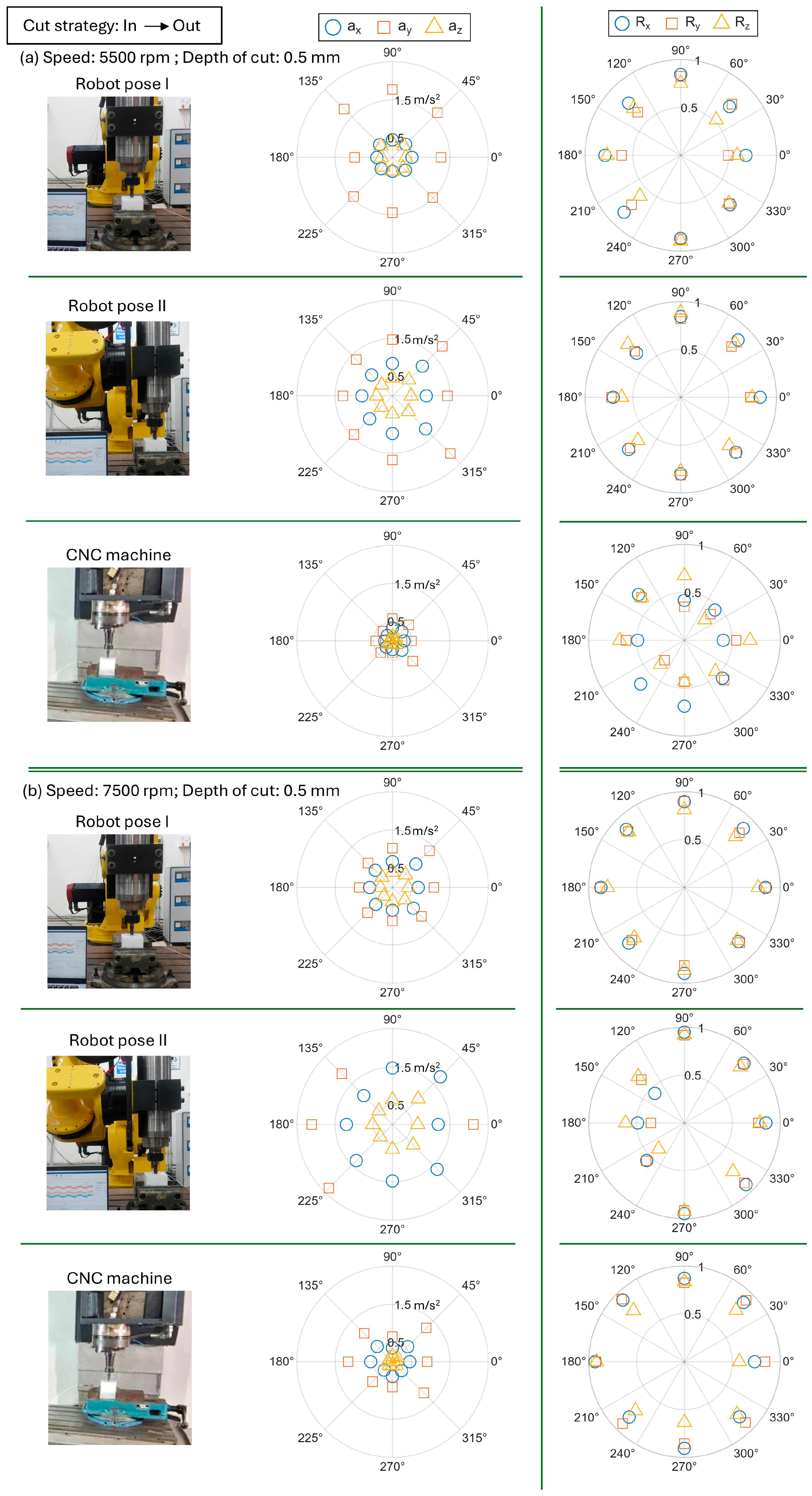
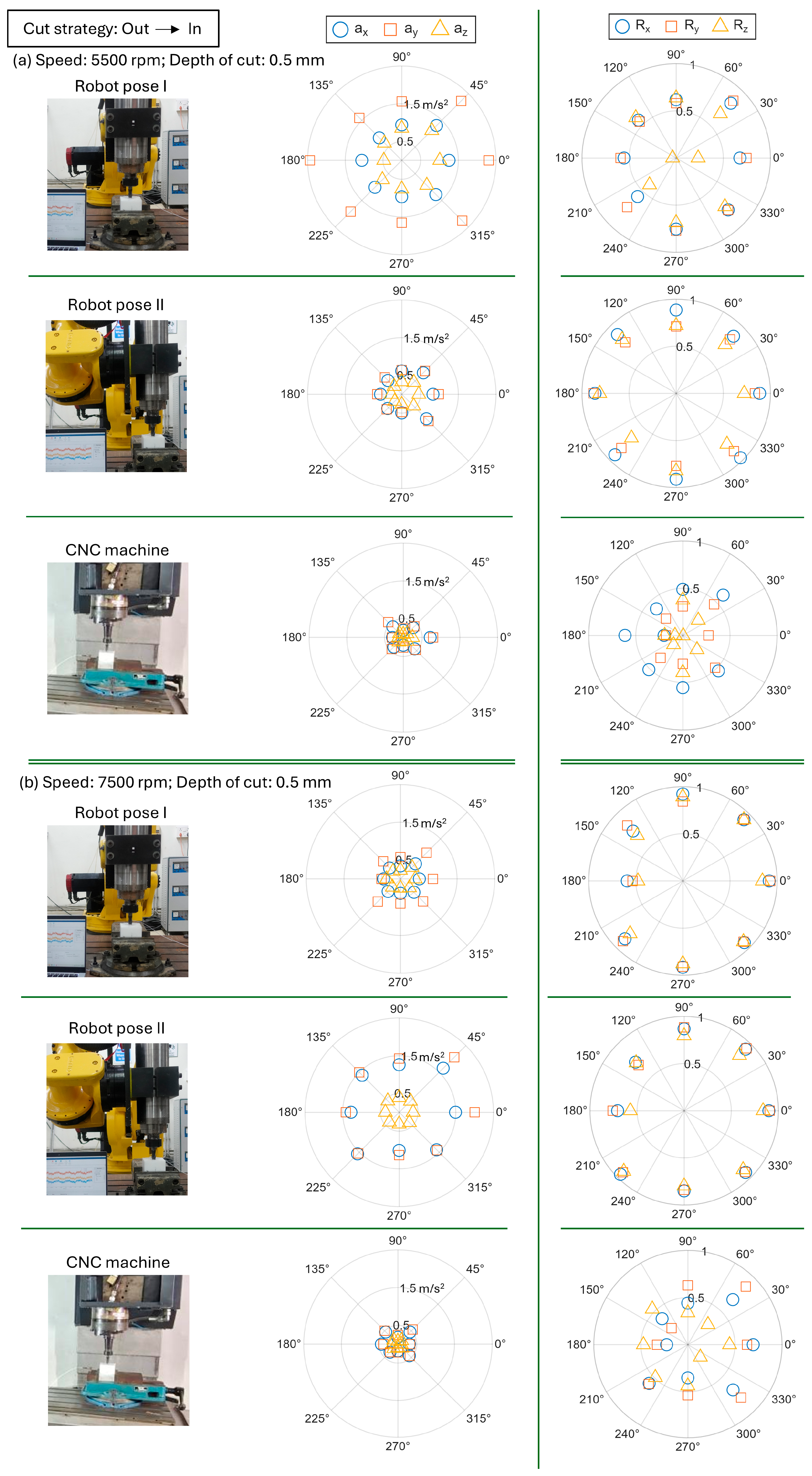
To avoid excessive repetition across all parameter combinations, summary polar plots are presented (
Figure 7 and
Figure 8). These plots display RMS acceleration and Poincaré correlation coefficients for each direction. The RMS values quantify overall vibration energy, while the correlation coefficients provide a scalar measure of periodicity, with values closer to unity indicating strongly rotation-synchronous motion and lower values reflecting modulation or cycle-to-cycle variability. This representation enables direct comparison of directional anisotropy, pose-dependent compliance, and speed effects without reproducing the complete signal sets for every case.
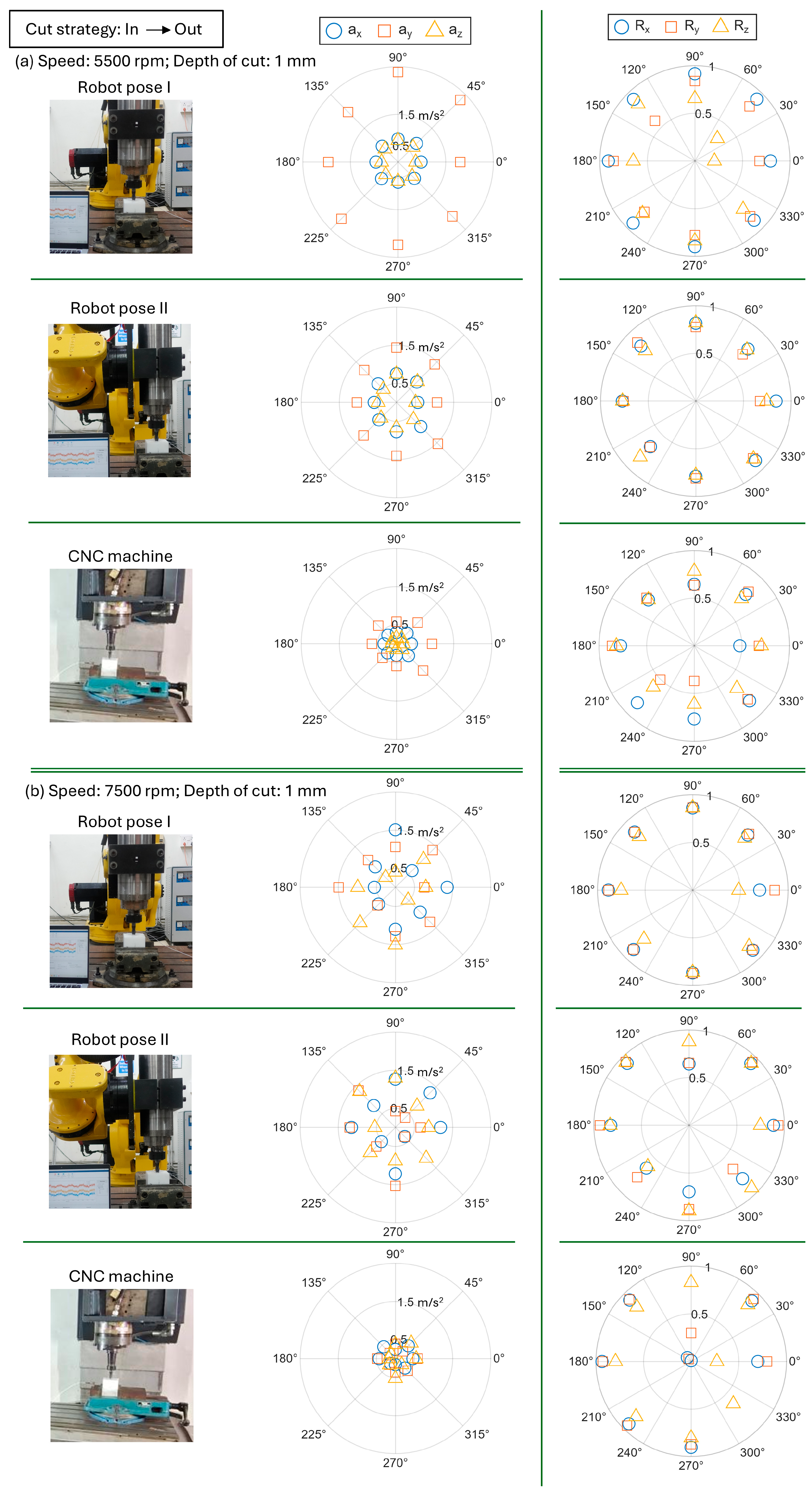
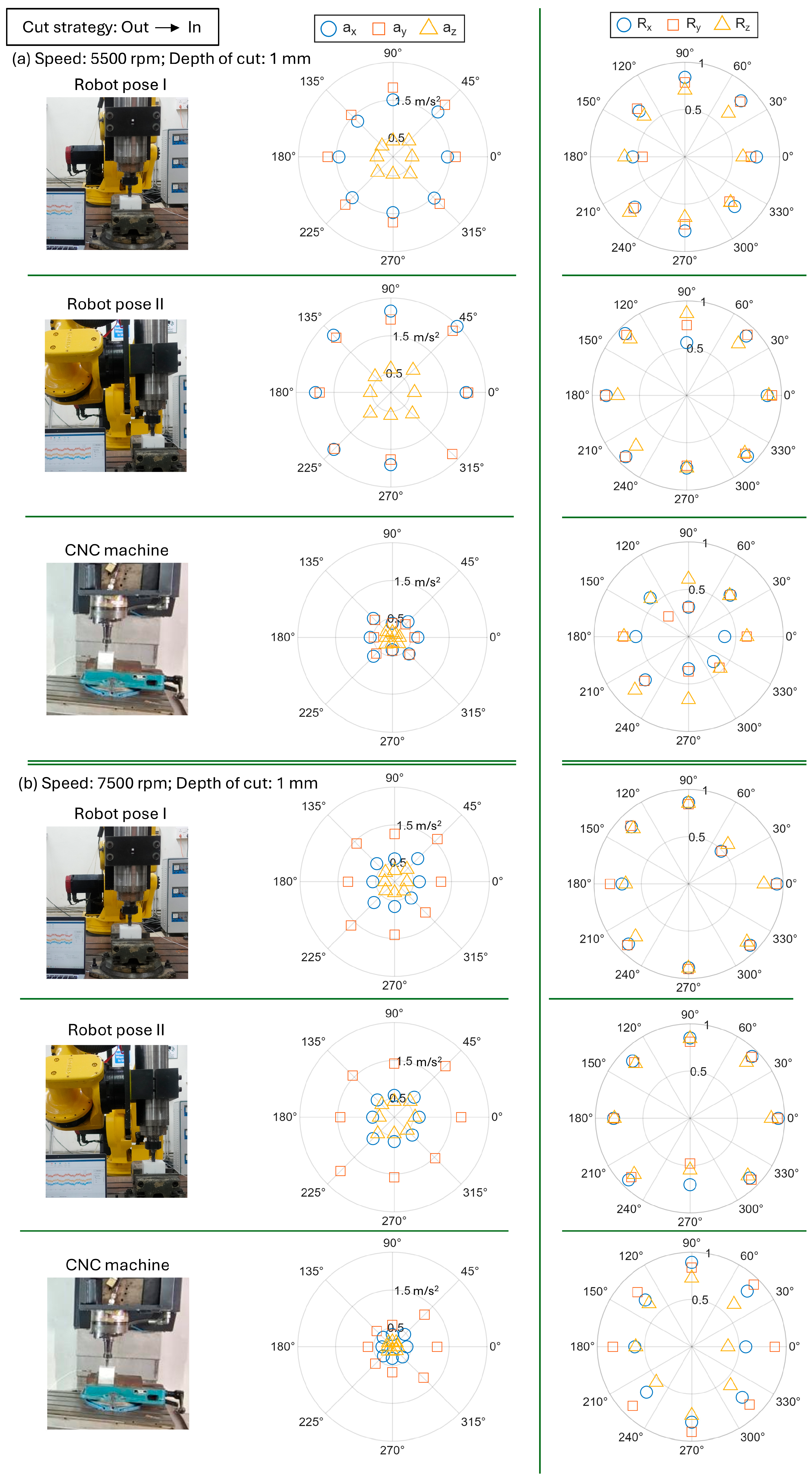
For Pose I, RMS levels are generally dominated by the Y-direction, with limited Z participation across orientations. In Pose II, the Z-direction RMS becomes more significant in orientations aligned with compliant structural directions, increasing total vibration energy and reducing periodicity. The CNC maintains relatively balanced in-plane RMS levels and minimal Z contribution, reflecting its higher vertical stiffness. Increasing spindle speed amplifies the dominant components while preserving pose-dependent anisotropy.
The Poincaré correlation coefficients follow trends consistent with RMS levels: orientations with elevated RMS exhibit reduced correlation, indicating stronger modulation. This coupling between vibration energy and loss of periodicity is most evident in Pose II. Although the CNC exhibits lower RMS amplitudes, its correlation values are not uniformly higher, reflecting the sensitivity of the metric to small broadband disturbances. RMS amplitude and correlation therefore characterize complementary aspects of the response. Changing cutting strategy (in–out versus out–in) produces measurable but secondary effects relative to pose and speed. In the robotic configurations, modest variations in RMS levels and correlation are observed—most noticeably in Pose II—but the fundamental anisotropic pattern governed by structural compliance remains unchanged. The CNC response is largely insensitive to strategy. The 1 mm depth cases (
Appendix A) show consistent behavior, with increased axial depth producing higher RMS levels and reduced periodicity in the robotic system. Overall, the vibration response of the robotic system is governed primarily by pose-dependent structural compliance, with spindle speed and depth of cut amplifying these effects. Increased compliance manifests as higher vibration energy, stronger cross-axis coupling, and enhanced modulation, particularly in Pose II.
5. Comparative Surface Quality in Robotic and CNC Milling
This section examines how variations in cutting direction, strategy (in–out versus out–in), spindle speed, depth of cut, and robot pose influence the achieved depth of cut and surface roughness. Polar representations are used to synthesize these effects and to assess correlations with the vibration characteristics identified in
Section 4.
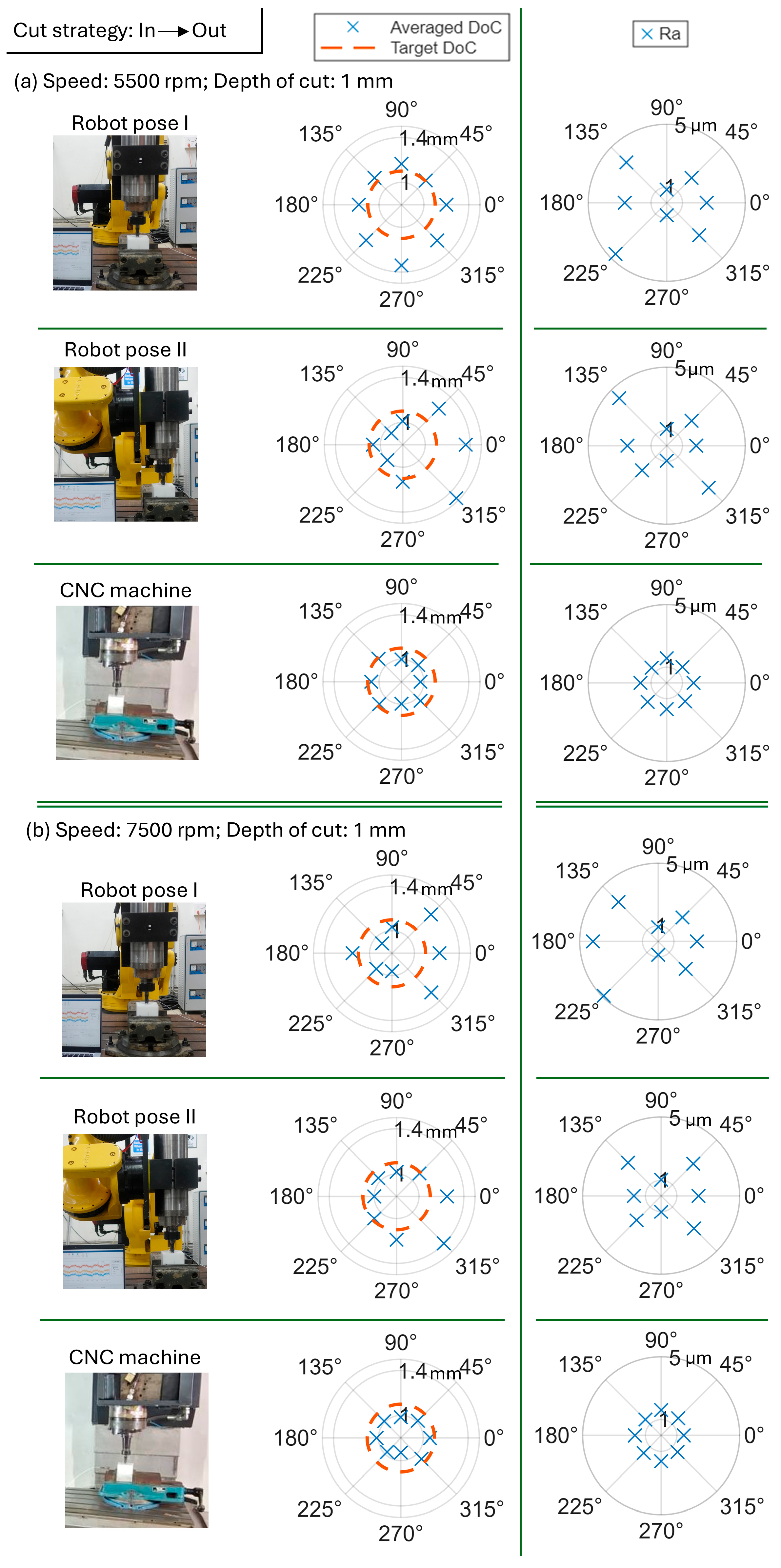
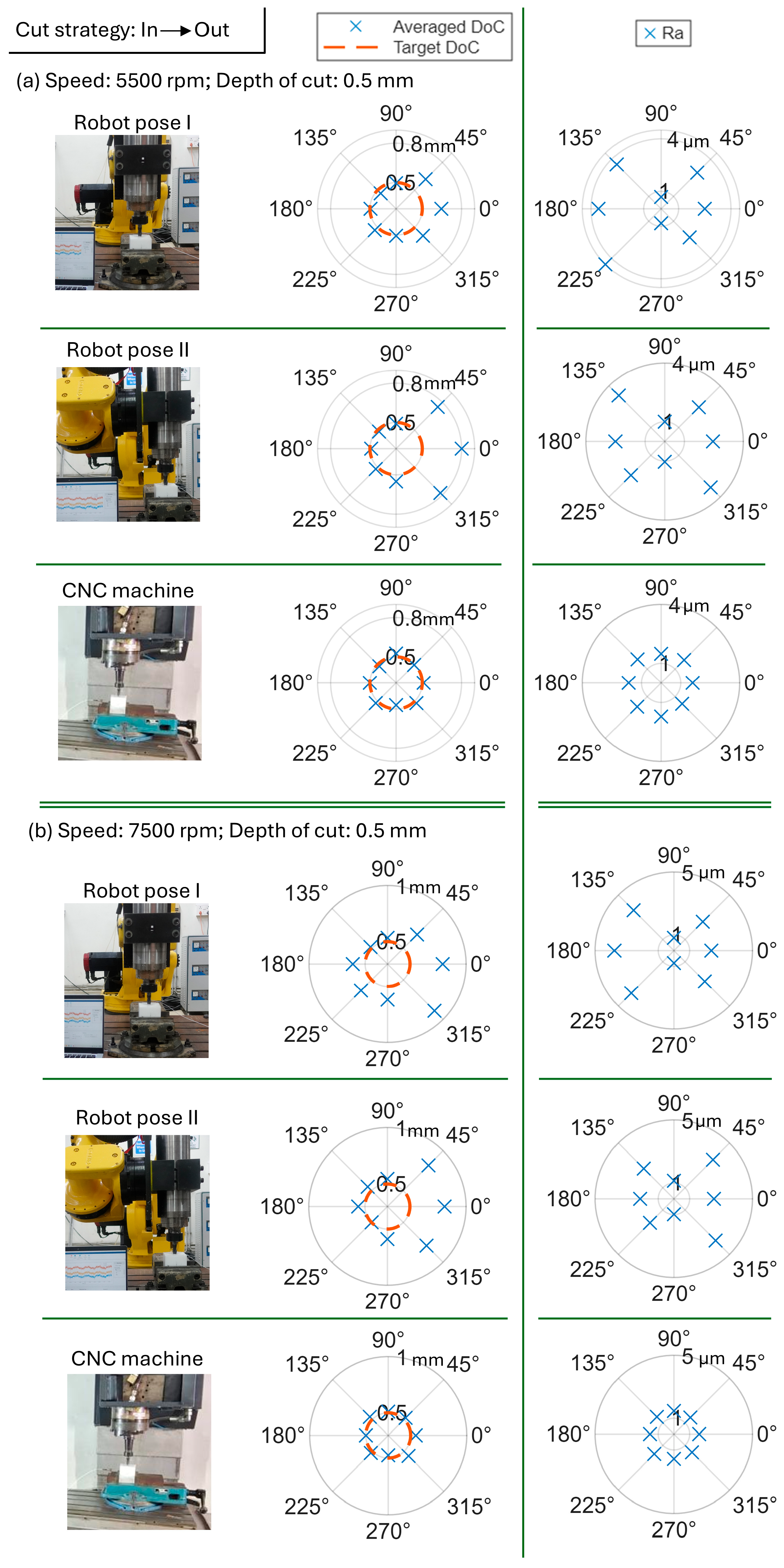
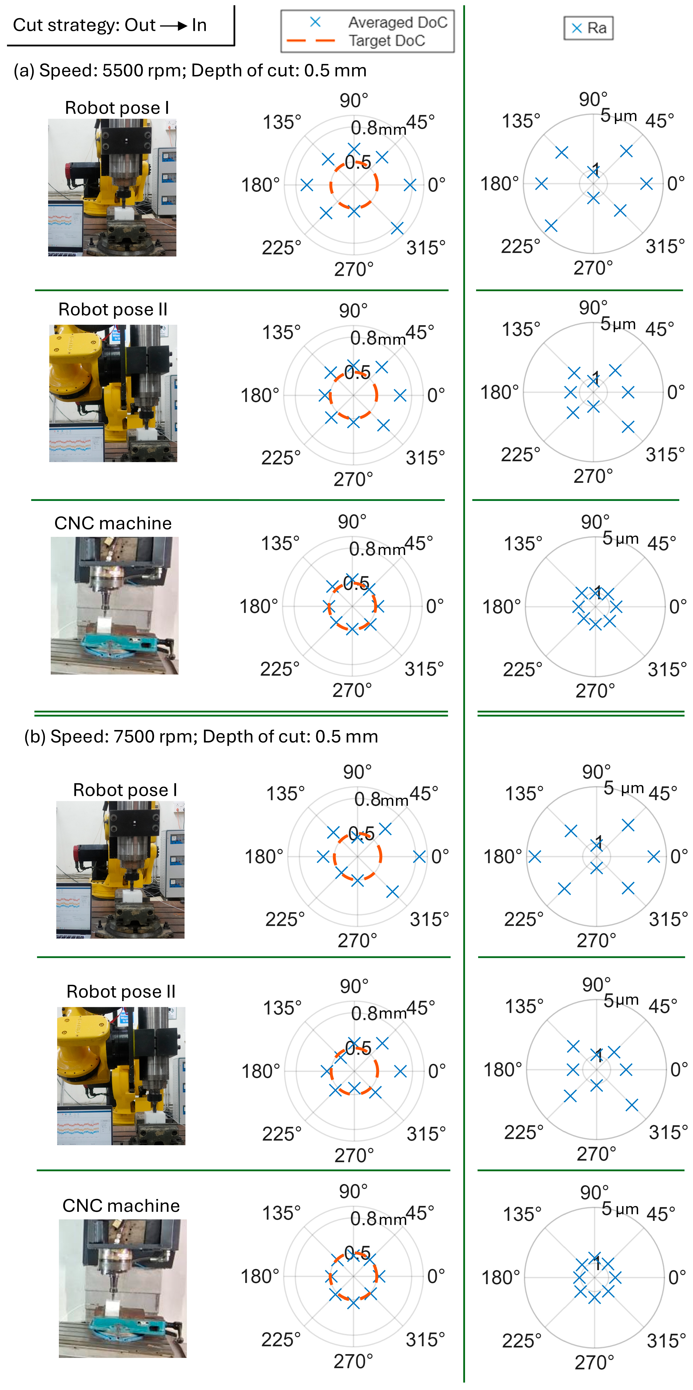
Representative results for a commanded axial depth of 0.5 mm under the in–out strategy at 5500 and 7500 rpm are shown in
Figure 9, with corresponding out–in results in
Figure 10. The figures present polar summaries of achieved depth of cut (DoC) and surface roughness (Ra) as functions of cutting orientation for Robot Pose I, Pose II, and the CNC machine. Although width of cut was also measured, it exhibited comparatively minor variation and is therefore not reported.
For the CNC, the achieved depth remains close to the commanded value across orientations, with only limited angular variation. In contrast, both robot poses exhibit clear angular anisotropy. Depth deviations increase along orientations aligned with more compliant structural directions, with Pose II showing the largest angular spread and consistent deviations in these sectors. This behavior correlates with the elevated Z-direction vibration amplitudes identified earlier, confirming orientation-sensitive dynamic deflection.
Surface roughness follows similar trends. Ra remains low and nearly invariant for the CNC, whereas the robotic configurations show increased roughness in orientations associated with larger depth deviations and higher Z-direction RMS vibration. Pose II exhibits both higher average Ra and stronger angular modulation.
Increasing spindle speed from 5500 to 7500 rpm preserves the angular patterns while slightly increasing their magnitude in the robotic cases. The CNC response remains comparatively stable with respect to both speed and orientation.
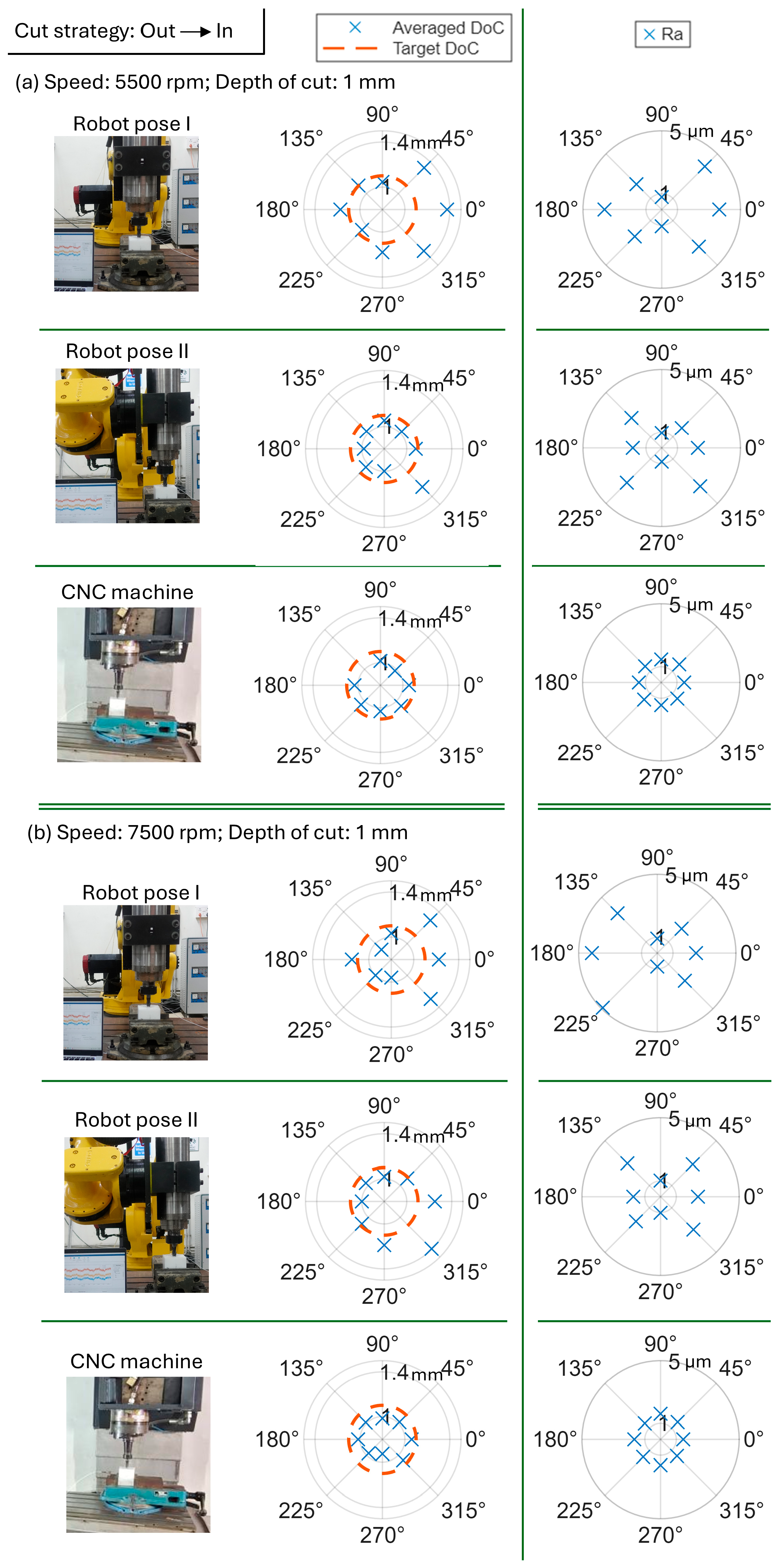
A comparison of the in–out (
Figure 9) and out–in (
Figure 10) strategies at identical speeds and axial depth (0.5 mm) indicates that the primary differences are observed in the robotic configurations, whereas the CNC response remains comparatively unchanged. For the robot, the out–in strategy produces modest changes in the angular distribution of achieved depth of cut, with slightly greater deviation in orientations aligned with more compliant structural directions, particularly in Pose II. These orientations also exhibit marginally higher Ra values, suggesting increased sensitivity of surface finish to engagement transients. In contrast, the in–out strategy results in somewhat more compact polar distributions and slightly reduced depth and roughness variation in those sectors. These observations indicate that reversal of engagement direction influences instantaneous force buildup and dynamic deflection, but does not fundamentally alter the orientation-dependent behavior governed by pose-dependent compliance. The CNC, owing to its higher structural stiffness, exhibits minimal variation between strategies in both depth accuracy and surface roughness.
Overall, the polar results demonstrate that dimensional accuracy and surface finish in robotic milling are strongly influenced by cutting orientation and pose, with the largest deviations occurring in the configuration exhibiting higher structural compliance and elevated Z-direction vibration response. The remaining cases at 1 mm axial depth for both cutting strategies are provided in
Appendix B, where similar pose- and orientation-dependent trends are observed.
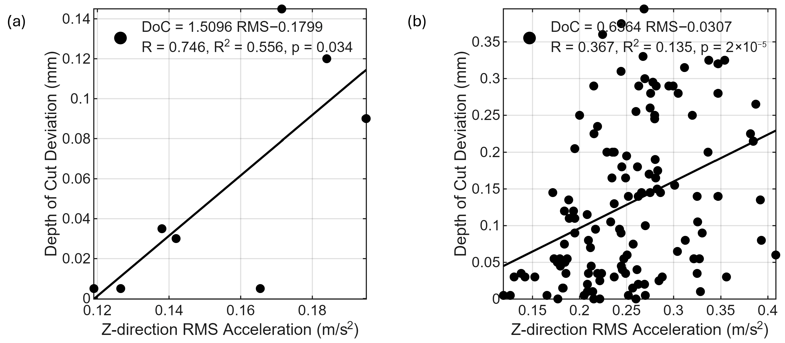
While the polar representations demonstrate clear orientation- and pose-dependent trends in achieved depth of cut and surface roughness, the preceding analysis remains primarily trend-based. To further examine whether the observed dimensional deviations exhibit a systematic association with vibration behavior, regression analyses were performed between Z-direction RMS acceleration and the magnitude of depth-of-cut deviation, defined as the absolute difference between commanded and measured axial depth. A representative single-condition analysis is first presented to illustrate the local relationship under fixed operating parameters, followed by a global regression incorporating all tested poses, spindle speeds, axial depths, and engagement strategies.
Figure 11a presents the regression between Z-direction RMS acceleration and the magnitude of depth-of-cut deviation for a representative condition (Pose I, spindle speed of 5500 rpm, axial depth of 0.5 mm, and the in-out cutting strategy). A statistically significant positive correlation is observed (R = 0.739, R
2 = 0.545,
p = 0.036). The positive slope indicates that higher vertical vibration levels are associated with larger dimensional errors, irrespective of whether the measured depth exceeds or falls below the commanded value. Under this fixed structural and process configuration, approximately 55% of the variation in dimensional error magnitude is explained by variation in Z-direction RMS acceleration, indicating a strong local correspondence between vertical vibration energy and dimensional accuracy degradation.
To evaluate whether this association persists across heterogeneous operating conditions, a global regression was performed incorporating all tested poses, spindle speeds, axial depths, and cutting strategies (
Figure 11b). A statistically significant positive correlation is again observed (R = 0.363, R
2 = 0.132,
p = 2.5 × 10
−5). Although the explanatory power decreases relative to the single-condition case, the persistence of the positive trend across diverse configurations indicates a consistent association between vertical vibration energy and dimensional error magnitude. The moderate coefficient of determination suggests that Z-direction RMS acceleration represents one contributing factor among several—alongside pose-dependent compliance redistribution, cutting orientation, and engagement conditions—in governing dimensional variability.
Importantly, by defining deviation in absolute terms, the regression isolates the relationship between vibration intensity and dimensional fidelity, independent of error direction. The results therefore indicate that increasing vertical dynamic excitation primarily degrades dimensional accuracy, rather than systematically biasing the process toward overcutting or undercutting.
6. Discussions and Practical Implications
The results show that robotic milling dynamics are governed by low-frequency structural compliance, which induces amplitude modulation of spindle-synchronous vibrations rather than direct resonance at structural natural frequencies. Although dominant structural modes occur below 20 Hz (
Section 3), the cutting response does not exhibit corresponding spectral peaks; instead, their influence appears as slow envelope modulation and cycle-to-cycle variability, reflected in broadened spindle harmonics and dispersed Poincaré sections. This indicates that periodic cutting forces interacting with compliant structural modes produce quasi-periodic modulation rather than resonance-driven amplification.
This behavior extends prior understanding of pose-dependent compliance in robotic milling, which has largely been interpreted in terms of vibration amplitude and chatter stability [
6,
7,
8,
9,
13,
14,
15,
16,
17]. The present results show that, under typical milling conditions, compliance primarily manifests through modulation of forced vibrations and loss of periodicity, which are not captured by conventional frequency-domain analysis alone [
11,
12].
Robot pose governs the distribution of compliance at the tool point and therefore directly influences both vibration amplitude and modulation strength. Configurations with higher compliance exhibit stronger modulation, broader harmonic spreading, and increased cycle-to-cycle variability. Cutting orientation further determines the alignment between excitation and structural compliance. Alignment with compliant directions increases cross-axis coupling, enhances modulation, and leads to larger Poincaré dispersion.
These dynamic effects directly influence machining performance. Orientations associated with higher Z-direction vibration consistently exhibit larger depth-of-cut deviations and increased surface roughness (
Section 5). Regression analysis confirms a statistically significant positive association between Z-direction RMS vibration and dimensional error, indicating that vertical dynamic response is a key contributor to accuracy degradation.
In contrast, the CNC machine exhibits predominantly rotation-synchronous behavior with minimal modulation and limited broadband content. The absence of significant low-frequency compliance results in a stable and repeatable response, even under higher cutting loads, confirming that the modulation observed in robotic milling originates from structural flexibility rather than the cutting process itself.
From a process planning perspective, these findings suggest that pose and cutting orientation should be selected to minimize alignment with compliant structural directions. While changes in cutting strategy (in–out versus out–in) influence engagement transients, their effect remains secondary to pose and orientation. Increasing spindle speed and depth of cut amplifies modulation effects but does not alter the underlying compliance-driven behavior.
Although the experiments were conducted on a low-force polymer to isolate structural effects, the identified mechanisms are expected to extend qualitatively to other materials, where higher cutting forces may further amplify modulation through stronger force–structure interaction.
7. Conclusions
This study presented a systematic experimental investigation of pose- and direction-dependent dynamics in robotic milling, benchmarked against conventional CNC machining under matched conditions. By combining tool-point FRFs with time–frequency analysis and spindle-synchronized Poincaré sections, a direct link is established between structural compliance, vibration modulation, and machining performance.
The results show that robotic milling dynamics are governed by low-frequency structural modes (≈8–20 Hz) with compliances on the order of 10−5 m/N, which are one to two orders of magnitude higher than higher-frequency tool–holder modes (~10−6–10−7 m/N). During cutting, these modes do not induce resonance; instead, they generate modulation of spindle-synchronous vibrations, manifested as cycle-to-cycle variability and broadband spectral spreading.
This modulation is strongly dependent on excitation–structure alignment and is amplified with increasing spindle speed and axial depth. Regression analysis demonstrates a statistically significant association between Z-direction vibration and depth-of-cut deviation (R = 0.739, R2 = 0.545 for a representative case; global R = 0.363, p < 10−4), directly linking vertical dynamic response to dimensional inaccuracy.
In contrast, the CNC system exhibits predominantly rotation-synchronous behavior with minimal modulation, reflecting its higher structural stiffness and absence of low-frequency compliance.
Overall, robotic milling performance is governed not only by stiffness magnitude but by the interaction between pose-dependent compliance, cutting direction, and modulation behavior. These findings provide a basis for configuration-aware process planning.
Future work will focus on developing predictive models that integrate robot structural dynamics with cutting mechanics to forecast modulation and dimensional error, and on extending the framework to harder engineering materials and more aggressive cutting regimes.