1. Introduction
In industrial practice, in-line hydrodynamic cavitation is commonly generated by static devices designed for a specific operating point, including Venturi devices with a circular throat [
1,
2,
3,
4,
5,
6]. In real processes, however, the processed medium and operating conditions evolve over time due to variations in temperature, viscosity, and gas or solids content, while the device geometry remains unchanged [
7,
8,
9]. As a result, maintaining an optimal cavitation regime within a prescribed process window becomes difficult over extended operating periods [
7,
8,
10]. In this context, controlled hydrodynamic cavitation is often intended as the regulation of operating conditions using plant-measurable variables, without modifying the installed cavitation generator [
10].
At the same time, many studies on cavitating Venturi devices focus on geometric design, optimization, and flow characterization, while assuming a configuration defined at the design stage and then kept constant during operation [
11,
12,
13,
14,
15,
16]. Variable-geometry Venturi devices have been developed in other fields to modulate performance quantities such as pressure drop or collection efficiency, but their objective differs from maintaining a cavitation regime within a target band for processing and treatment applications [
17,
18,
19,
20,
21].
In the available literature, variable-geometry Venturi concepts are most often based on the actuation of a single geometric variable, with throat adjustment used to influence global performance measures. This approach is not usually presented within a normalized configuration-space framework aimed at control-oriented cavitation regulation, and it does not explicitly address the requirement of maintaining cavitation intensity within a prescribed band under time-varying process conditions. Furthermore, independently imposed swirl forcing is not commonly treated as a second actuated variable to be coordinated with throat reconfiguration. Finally, the distinction between configurations that are admissible by design and those that are physically achievable in operation is not always made explicit [
17,
18,
19,
20,
21].
From a plant perspective, it therefore remains relevant to formalize a reconfigurable cavitating Venturi that preserves in-line integration by keeping external interfaces unchanged, while making the internal configuration an operating variable for stabilizing and positioning the cavitation regime with respect to a defined process target.
In many process-intensification and extraction scenarios, the optimal cavitation operating window for a given target compound is not known as a priori and cannot be inferred reliably from design-stage assumptions.
A reconfigurable Venturi can therefore be used as a scouting and characterization platform: the throat configuration and boundary conditions are intentionally swept within a declared admissible/achievable set to identify the configuration and operating conditions that maximize a process performance metric (e.g., extraction yield, selectivity, purity, or minimal degradation) under the actual fluid properties and plant constraints.
Once this target window is identified, the same module can be operated either as a fixed-configuration device (set-and-lock) for a single-compound production line, or as an in-line actuator for maintaining the target performance under feed and operating variability through configuration-based regulation.
This work proposes the DVRA, a Reuleaux-section Venturi module designed for in-operation regulation of the cavitation regime through device configuration [
22,
23,
24]. The module integrates two configuration degrees of freedom. The first is a reconfigurable effective hydraulic throat implemented through an actuated elastomeric liner, with a clear distinction between a reference throat and the effective hydraulic throat [
19,
20,
21]. The second is boundary-imposed swirl forcing achieved through rotational boundary conditions applied at the module ends by external collars, without rotating parts immersed in the fluid and without requiring rotation of the process line. Operational definitions and conventions are introduced to provide an unambiguous and reproducible description of the device configuration, and a configuration space is formalized using normalized inputs, distinguishing admissible configurations from those that are practically achievable. A control-oriented framework casts regulation as an inverse mapping based on an in-line cavitation indicator estimated from standard industrial measurements of flow rate, pressure, and temperature.
This manuscript focuses on device architecture, operational definitions, and the configuration-space framework, while application-specific characterization and performance assessment are addressed separately.
The remainder of the manuscript presents the device architecture, the operational definitions required for a reproducible configuration description, and the control-oriented formulation of the regulation problem.
2. Operational Definitions and Notation
To describe the DVRA in a clear, unambiguous, and reproducible manner, this section introduces operational definitions for the throat, the actuation inputs, and the rotational boundary conditions. No predictive models are introduced.
From a fluid-dynamics perspective, the device retains the structure of a Venturi and includes a converging section, a throat region, and a diverging section. To make the geometry and boundary conditions unambiguous, three reference sections are defined. Section A identifies the DVRA inlet, section B identifies the outlet, and section T identifies the reference section at the throat. This choice makes it possible to distinguish two functional segments, A-T and T-B, which are used to define upstream and downstream rotational forcing with respect to the throat.
In the DVRA, a distinction is required between the reference throat and the effective hydraulic throat. The reference throat is a geometric and structural reference used to describe the device. The effective hydraulic throat coincides with the internal surface actally seen by the fluid and is determined by the elastomeric liner; therefore, it is a configurational quantity and can vary during operation. The hydraulic throat can be described operationally through equivalent geometric quantities, including the throat area
, the wetted perimeter
, and the equivalent hydraulic diameter
[
8].
Reconfiguration of the hydraulic throat is specified by normalized inputs
, with
. Boundary swirl forcing is specified by
and
. The vector of dimensionless inputs is defined as
where
specify liner reconfiguration and
,
specify boundary-imposed swirl forcing. Throat geometric quantities, such as
,
, and the derived equivalent quantities, are treated as functions of the throat subvector
and can be obtained through a geometric–kinematic mapping or calibration. Swirl forcing is imposed as a rotational boundary condition at the module ends and is described by the angular velocities
at the inlet (section A) and
at the outlet (section B). These angular velocities are applied through external wheels or collars. Rotation is transferred to the internal DVRA structure, including the mechanical cage and the elastomeric liner, and does not require rotation of the process line.
The essential device element consists of three rigid segments A-T-B connected by 360° spherical joints. Operation can occur in a locked state, in which no relative rotation is allowed between segments, or in a free state, in which relative rotations are allowed. This distinction provides an unambiguous description of whether a differential rotational forcing can be applied across the throat.
To separate upstream and downstream rotational forcing with respect to the throat section T, relative rotations are introduced for the two module segments. The relative rotation in the A-T segment is defined as
where
is the angular velocity associated with the throat reference section T. Similarly, the relative rotation in the T-B segment is defined as
The quantities and are introduced as operational conventions to distinguish and compare rotational forcing upstream and downstream of section T. These definitions provide the basis for the classification of the operating modes introduced in the following sections. The quantity is a kinematic reference associated with section T. When the throat reference at T is locked, in the external (non-rotating) frame; hence and . When the reference at T is free, is not imposed and can be treated as an internal variable. In that case, explicit evaluation of and requires measuring (e.g., an encoder at T) or estimating it from the A-T-B kinematics; mode selection can still be implemented operationally by enforcing the locked/free constraints and by the imposed boundary conditions at A and B.
3. DVRA Architecture and In-Line Integration
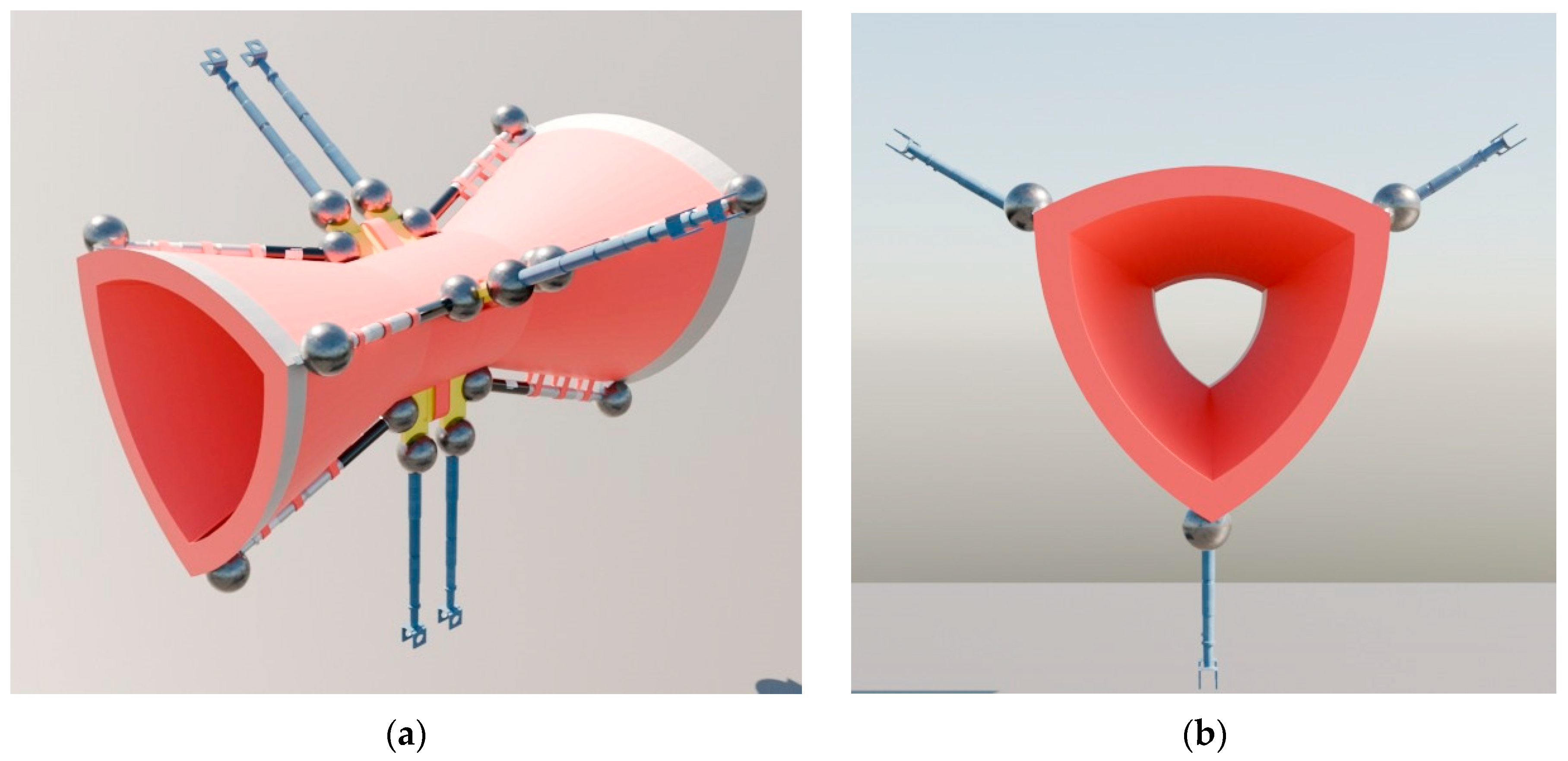
The DVRA is a Reuleaux-section Venturi module designed for in-line installation and for use as an actuatable component in continuous processes. The regulation function is integrated into the device through an architecture that combines a continuous internal surface, defined by an elastomeric liner, with a constraint-and-guidance structure consisting of a mechanical cage, which transfers the commands and imposes the kinematic envelope. A consistent color code is adopted throughout the manuscript to identify the subsystems, namely the reference throat (yellow), the structural cage (white), the elastomeric liner and hydraulic surface (red), the liner actuators (blue), and the 360° spherical joints (black). An overall view of the module is reported in
Figure 1.
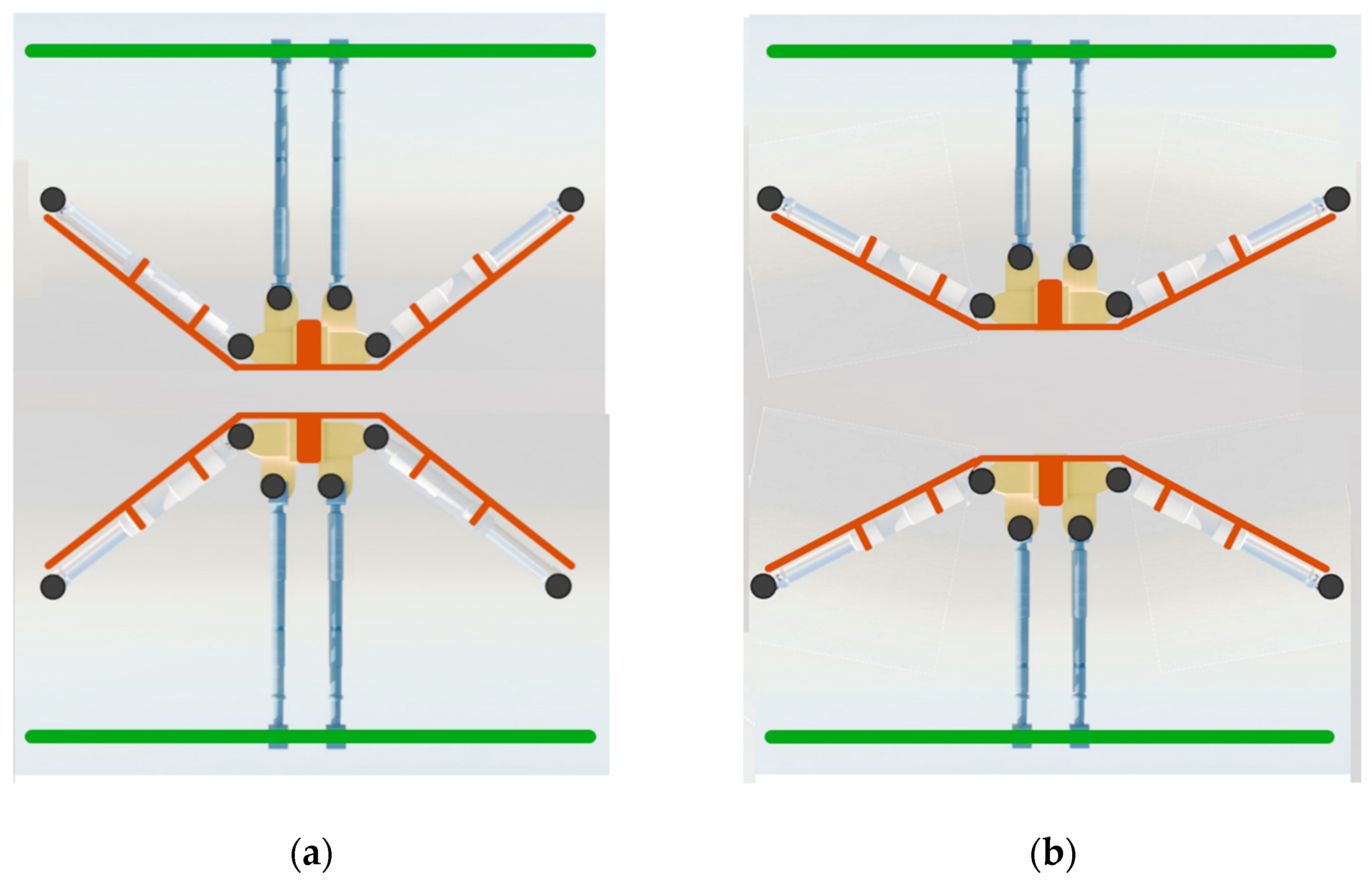
From a fluid-dynamics perspective, the device retains the classical Venturi structure, including a converging section, a throat region, and a diverging section. From a mechanical perspective, the combination of the cage and the liner separates the structural reference from the effective hydraulic section. The reference throat provides a stable geometric frame, whereas the effective hydraulic section can be modified during operation through controlled liner deformation. The liner enables a continuous change in the cross-section without internal wall discontinuities (
Figure 2). The cage guides the deformation and bounds its operating domain, thereby contributing to configuration repeatability.
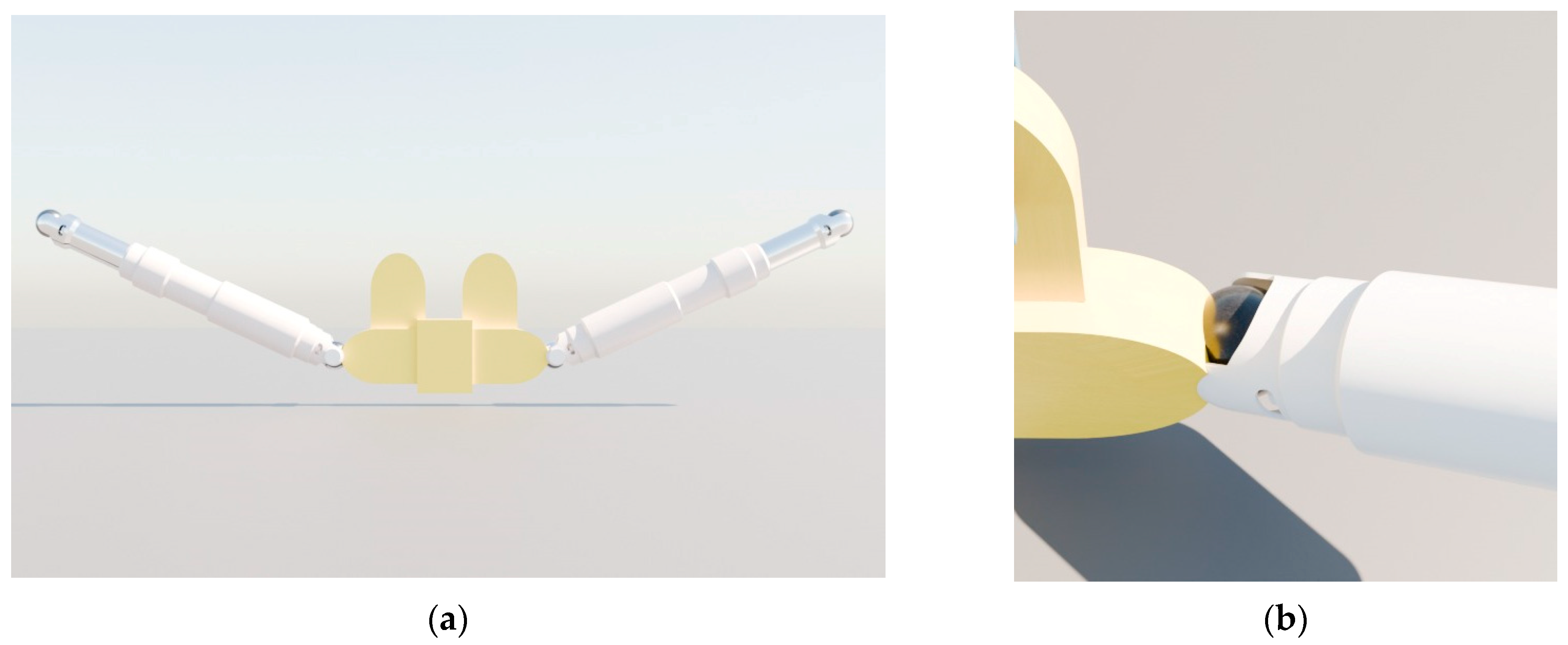
The essential construction unit of the DVRA is an element composed of three rigid segments A-T-B, connected by 360° spherical joints that allow relative rotations and local misalignments between components. This architecture reduces undesirable kinematic constraints when torsion and throat-surface deformation are combined. Operationally, the A-T-B element can operate in a locked state, in which relative rotations between segments are not allowed, or in a free state, in which relative rotations are allowed. The logic of the elementary module and the use of the spherical joints are illustrated in
Figure 3.
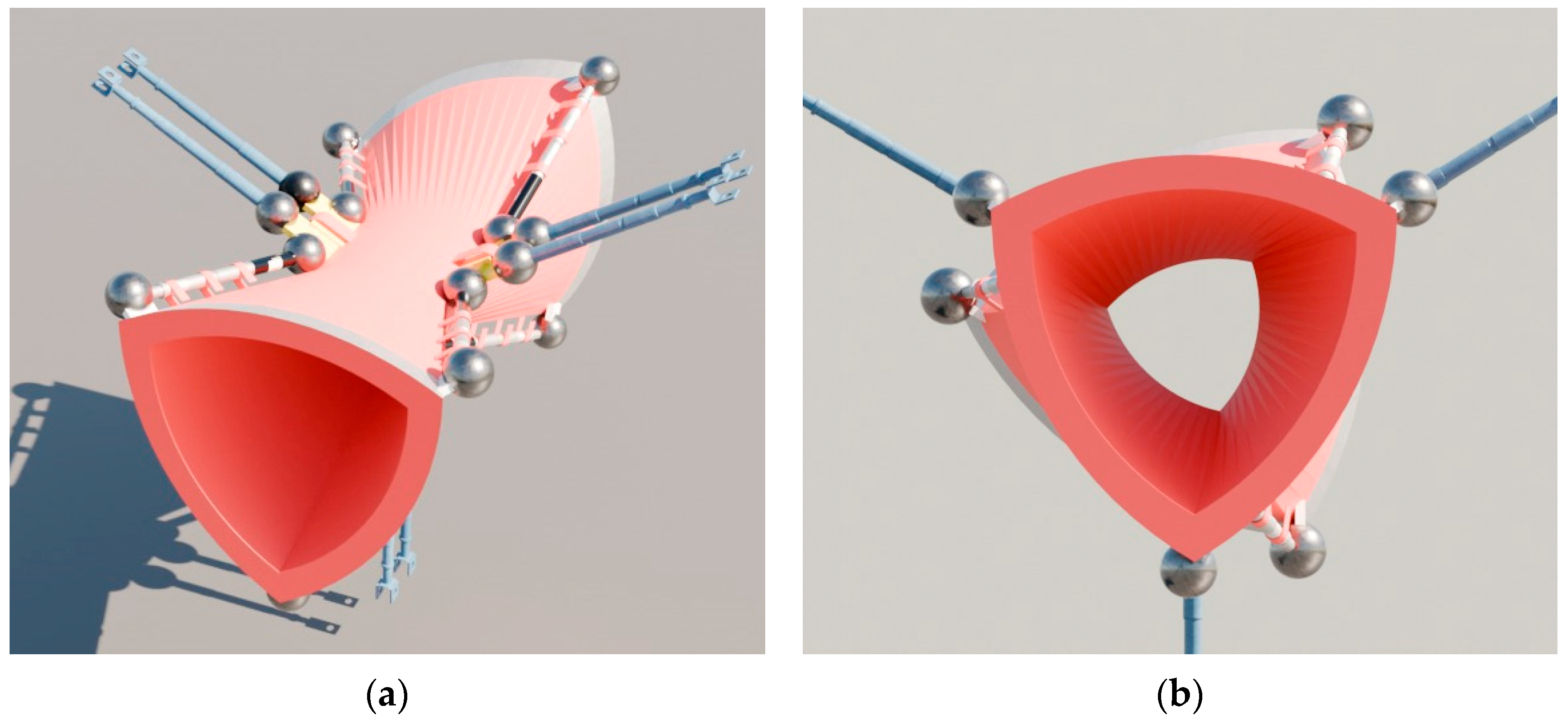
For in-line integration of the DVRA, geometric transitions between circular pipes and the Reuleaux cross-section are provided to ensure compatibility with connections and constraints typical of continuous-process plants. When enabled, swirl forcing is implemented through external wheels or collars at ends A and B. Collar rotation imposes the angular velocities
and
and transfers motion to the internal DVRA structure. An overall view of the integration and the collar placement at the ends are reported in
Figure 4.
4. Dynamic Throat Regulation
DVRA throat regulation is achieved by acting on the local section in the vicinity of the constriction, thereby modifying the conditions that govern cavitation inception and the stability of the cavitating regime [
7,
8,
9,
10]. In this work, the throat is not treated as a fixed geometry but as a configuration variable that can be modulated over time through actuation, while the structural reference associated with the throat remains stable and is used as a frame for definitions and control [
17,
18,
19,
20,
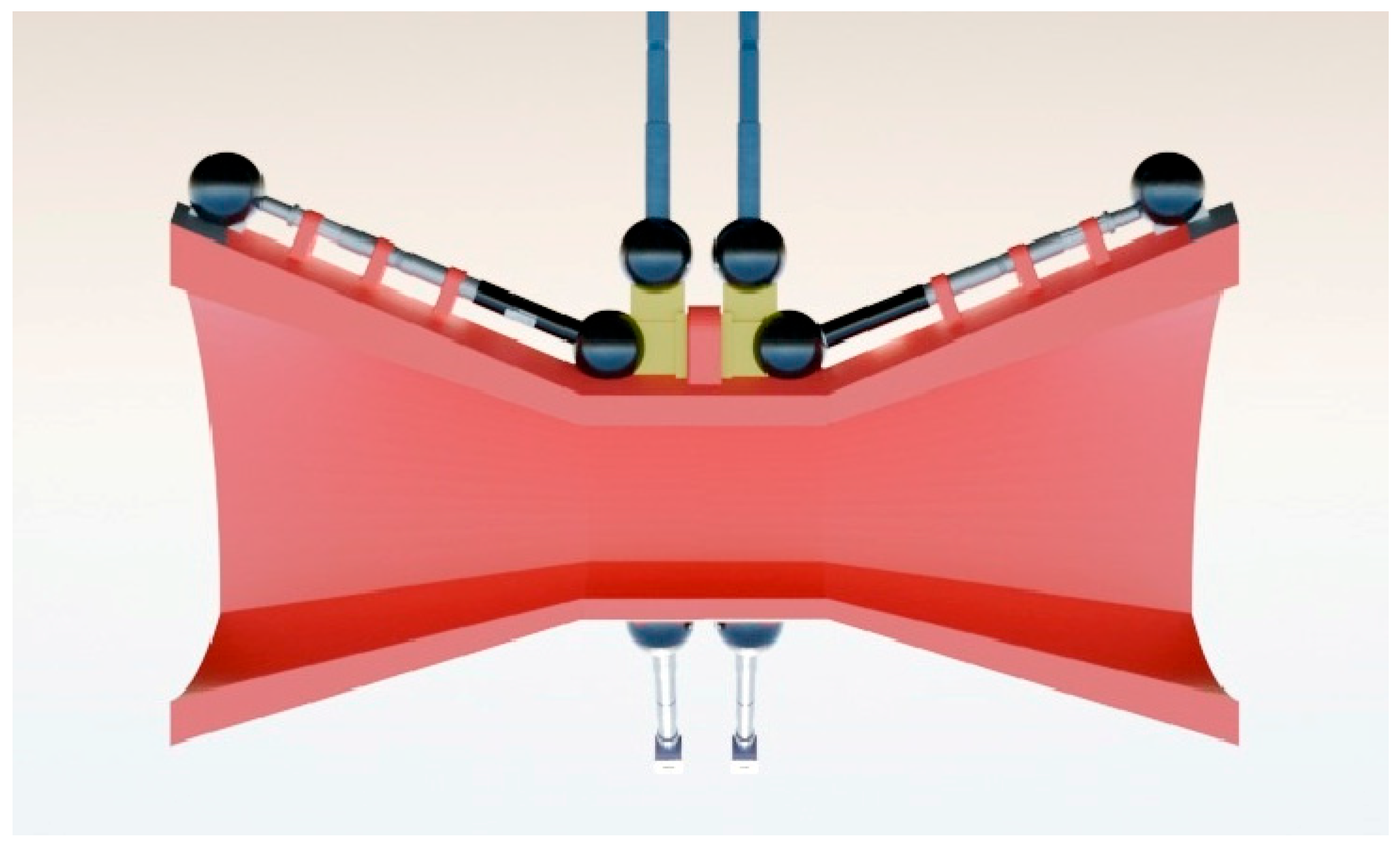
21]. The elastomeric surface enables controlled and continuous deformation, avoiding internal wall discontinuities and making regulation compatible with in-line operation. The dynamic-throat concept is illustrated in
Figure 5.
Variation in the hydraulic throat is specified by normalized inputs , collected in the vector . This section considers only the throat component , which governs liner deformation. No specific constitutive law is assumed for the liner; instead, the existence of a repeatable relationship between and the resulting hydraulic geometry is assumed, defined within a declared operating domain. The throat is described operationally through equivalent quantities such as the area and, when useful, the wetted perimeter and the equivalent hydraulic diameter .
The elastomeric liner may introduce non-idealities, including hysteresis and dependencies on temperature and loading conditions, which are treated as part of the operating domain. For implementation and replicability, it is therefore necessary to specify the achievable throat range and the constraints imposed by kinematics and actuation, together with the repeatability requirements of the command–geometry relationship. To this end, it is useful to report the minimum parameters that characterize throat regulation, including the maximum command excursion of
, the corresponding excursion of the throat geometric quantities, and the characteristic axial length of the throat region along the module axis [
25].
In this formulation, constitutes the command, and the effective hydraulic throat constitutes the configurational variable that modifies the local flow conditions and, indirectly, the cavitation operating window. Throat regulation remains available regardless of whether the A-T-B element is in the free or locked state, because it acts on the liner geometry and does not require relative rotations between segments.
5. Swirl Forcing and DVRA-CR and DVRA-RR Operating Modes
Swirl forcing is the second configurational action of the DVRA and enables a rotational boundary condition to be imposed at the device ends without rotating elements immersed in the fluid [
26,
27]. In this work, swirl is defined in an operational sense and does not require quantification of the tangential flow field in the fluid, which would require dedicated measurements or simulations.
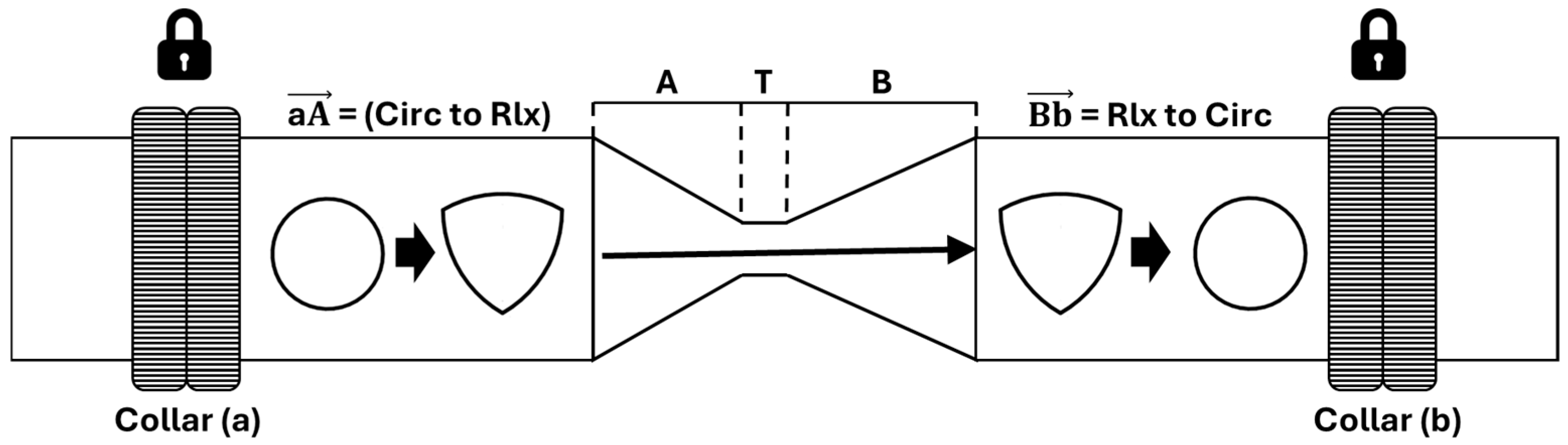
The forcing is implemented through external collars at ends A and B that impose the angular velocities and . Rotation is transferred to the mechanical cage and the elastomeric liner, whereas the process line does not rotate. The device includes an A-T-B element with 360° spherical joints and can operate in a locked or free state. Swirl forcing requires the free state, and in the DVRA-RR mode the reference at T is additionally constrained to make the direction reversal across the throat unambiguous.
Operating modes are defined with respect to section T, which separates the A-T and T-B segments. The baseline mode corresponds to
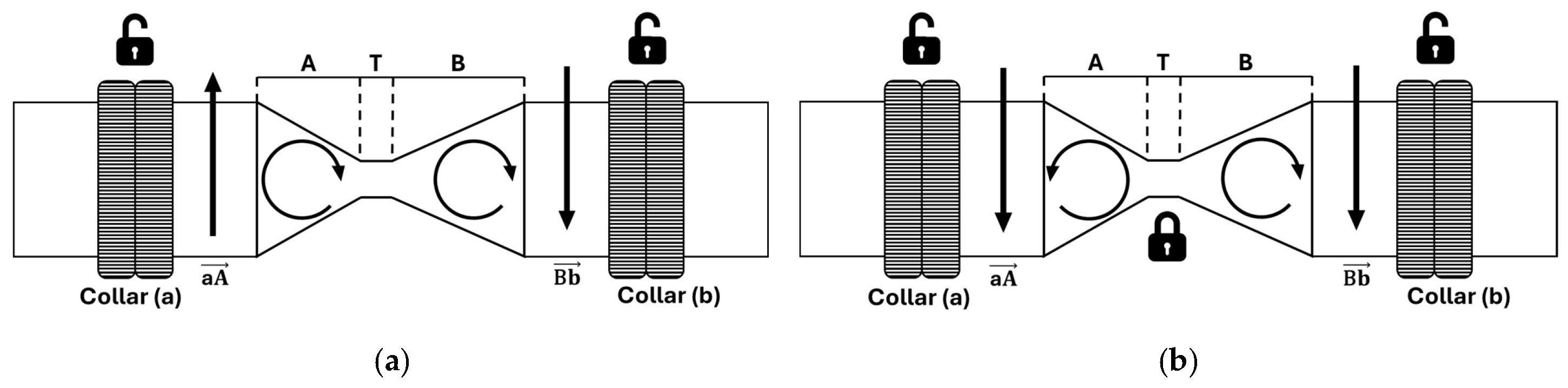
. The DVRA-CR mode, where CR denotes concordant rotation, describes configurations in which the forcing direction is consistent upstream and downstream of the throat, whereas the DVRA-RR mode, where RR denotes reversed rotation, describes configurations in which the forcing direction reverses across section T. The classification as a function of the A-T-B state and the state of reference at T is reported in
Table 1.
To fix the flow-direction convention and the locked/free constraint notation used in the operating modes, the conceptual configuration scheme is reported in
Figure 6.
The flow direction is assumed from left to right. Padlock symbols indicate the rotation-constraint state, with a closed padlock denoting the locked state and an open padlock denoting the free state. Arrows qualitatively indicate the direction of the tangential forcing in the A-T and T-B segments. In the DVRA-CR mode, the forcing does not reverse across T. In the DVRA-RR mode, the forcing reverses across T and section T must be locked to make the distinction between the two segments unambiguous. An overall view of the DVRA and a visualization of the module interior are reported in
Figure 7.
6. Admissible Inputs and Design Space of the DVRA
To describe the DVRA in an unambiguous and reproducible manner, an admissible input set , defined over dimensionless commands, and a design space , defined over the configuration vector , are introduced. The configuration includes the effective hydraulic-throat geometry at section T and the boundary-imposed swirl forcing at sections A and B. The kinematics of the A-T-B element, expressed by the free or locked state, is treated as a mode parameter and is recalled in the definition of the operating modes.
The vector of dimensionless inputs
is defined in (1), where
command liner reconfiguration and
and
command boundary-imposed swirl forcing. The admissible input set is defined as
In the following, is assumed. The parameter depends on the mechanical implementation and on the actuation discretization.
The boundary-imposed angular velocities are obtained by scaling within the admissible limits:
The same definition is adopted for the outlet boundary:
The normalized commands are unsigned. The direction of the imposed boundary rotation is therefore encoded in the admissible limits and . In particular, if the limits straddle zero (e.g., ), then the sign of can change even though is unsigned. The neutral command associated with is (analogously for B). In industrial implementations, the same mapping can be realized equivalently as a magnitude command in [0, 1] plus a direction bit.
The throat-input subvector is denoted by
. The effective hydraulic throat at section T is described by the area
and the wetted perimeter
of the internal section effectively seen by the fluid. The equivalent hydraulic diameter is introduced as
This definition is also valid for non-circular sections, including a Reuleaux-triangle throat. The throat region is further described through equivalent parameters , , and , where is the equivalent length of the throat region and and are the equivalent angles of the converging and diverging sections. The mappings , , , , and are determined by the liner kinematics and can be obtained through a geometric–kinematic mapping or calibration.
A compact configuration vector is then defined as:
The design space
is the set of admissible configurations:
Although the present implementation uses a Reuleaux triangular throat, the design space is defined through normalized inputs and equivalent hydraulic descriptors of the throat section, including cross-sectional area, wetted perimeter, and hydraulic diameter. These descriptors are well-defined for arbitrary cross-sectional shapes, so the framework is not restricted to the Reuleaux geometry. Extending the framework to a different throat shape only requires updating the geometric–kinematic mapping that relates actuator commands to the equivalent descriptors, together with the corresponding admissible bounds. Scaling to different pipeline sizes follows the same normalized formulation, with geometric variables expressed relative to the line diameter and the admissible set re-identified from actuator stroke limits, liner characteristics, and collar speed limits.
Equivalently,
can be described through operational limits related to geometry, materials, and actuation:
Kinematic constraints and non-idealities further restrict the configurations that are practically achievable. Therefore, an achievable subset of inputs
is introduced, together with the corresponding set of achievable configurations:
Operating modes are defined with respect to the throat section T, which separates the upstream segment A-T from the downstream segment T-B. The baseline mode is defined by the absence of boundary-imposed swirl. The DVRA-CR mode corresponds to a tangential forcing that is concordant upstream and downstream of the throat and can be implemented with the reference at T either free or locked. The DVRA-RR mode corresponds to a tangential forcing that is discordant across T and requires the reference at T to be locked.
When the reference at T is constrained,
is assumed; therefore,
and
. The operating mode is determined by the sign of
(
Table 1), as illustrated in
Table 2.
The proposed formulation is grounded in how throat configuration and boundary-imposed swirl act on the pressure field governing cavitation. For a given flow rate, the throat setting determines the mean throat velocity
and thus the characteristic dynamic-pressure scale. Cavitation propensity depends on the local minimum pressure relative to vapor pressure and may be characterized by a cavitation index based on the available pressure level and
. Boundary-imposed swirl alters the pressure field through a radial pressure gradient and axial-momentum redistribution, which can shift both the location and value of the minimum pressure in the throat and diffuser region. Throat configuration and boundary-imposed swirl therefore act on the same governing quantity, the minimum pressure, and their effects are expected to be coupled with respect to cavitation onset and extent.
Table 3 summarizes representative Baseline, DVRA-CR, and DVRA-RR cases and the associated throat-velocity scaling.
7. Control-Oriented Framework and Inverse Mapping
The DVRA is an in-line actuatable module that enables regulation of the cavitating regime through device configuration. In continuous processes, the operational objective is to keep cavitation within a target band despite variations in flow rate, available pressure, temperature, and fluid properties. A control-oriented framework links in-line measurements to configuration variables and actuator commands.
Regulation is achieved through two configurational actions. The first concerns the effective hydraulic throat at section T, modulated by the commands . The second concerns boundary-imposed swirl forcing, specified by and , which imposes rotational boundary conditions and enables the baseline, DVRA-CR, and DVRA-RR operating modes. In this work, these actions are treated as configuration variables, and the availability of measured or simulated fluid-dynamic fields is not assumed.
The problem is formulated as the selection of an achievable configuration from inputs . The formulation is inverse in nature: given a target band for a cavitation indicator that can be estimated in line, such as the cavitation number or an equivalent metric, the regulation selects and the operating mode to keep the indicator within the band. Performance under disturbances and process variations depends on application-specific characterization.
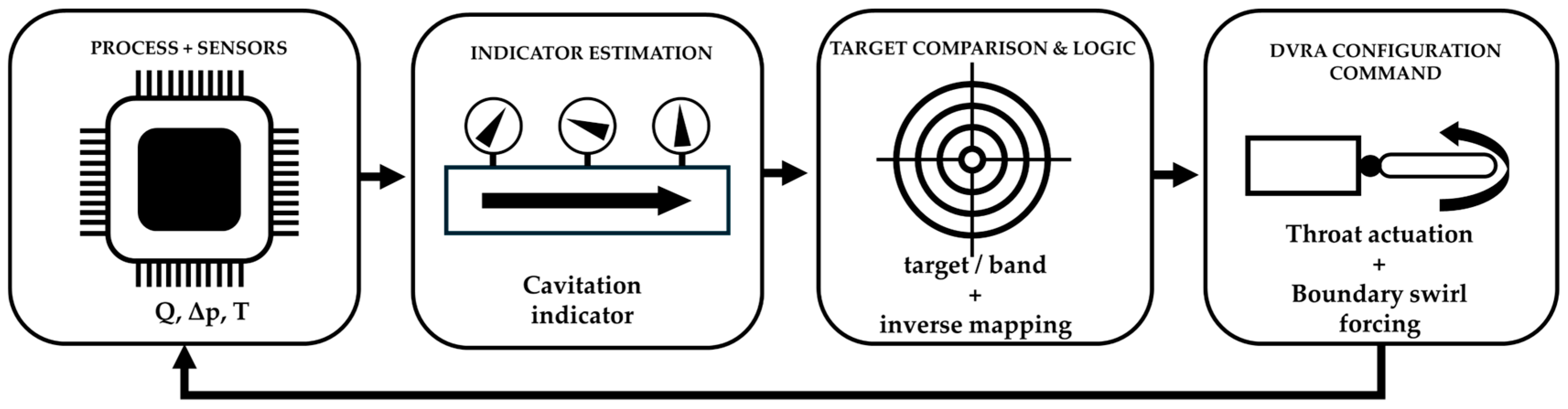
Implementation requires a sensor–actuator loop based on industrial measurements.
Figure 8 reports a conceptual diagram in which flow rate, pressure, and temperature feed the estimation of the cavitation indicator; comparison with the target generates configuration commands, which are translated into
,
, and
.
8. Implementability, Replicability, and Scope Limitations
The DVRA is designed for installation as an in-line module. The architecture separates the process line from the actuation subsystem by confining throat regulation and boundary-imposed swirl forcing within the device through the mechanical cage, the elastomeric liner, and the end collars at sections A and B. The process line does not need to rotate, thereby reducing plant impact and simplifying integration in continuous processes.
Replicability requires reporting the geometric references and the DVRA degrees of actuation. The minimum information required to reconstruct the module geometry, to describe the effective hydraulic throat at section T, and to reproduce the logic of the operating modes defined with respect to T should be provided. This minimum information is summarized in
Table 4.
The elastomeric liner enables a variable throat and a continuous internal surface, but it introduces non-idealities that should be reported. The response to the commands may exhibit hysteresis and dependencies on temperature and loading conditions. In industrial operation, these effects can be mitigated through feedback control, provided that the command–geometry relationship is repeatable within a defined operating domain and after calibration or identification.
Swirl forcing may also introduce non-idealities. Torque transmission to the collars may lead to backlash, dead zones, and saturation, which are considered part of the operating domain. Moreover, the spherical joints improve kinematic compatibility but impose finite limits on admissible angles and loads. The combination of boundary-imposed torsion and throat reconfiguration should therefore remain within a configurational envelope that avoids interference, actuator saturation, and excessive liner stresses.
This work focuses on device architecture, operational definitions, and a control-oriented framework. Neither CFD nor dedicated experimental campaigns are employed, because cavitation predictions without data and without verification and validation would not be sufficiently robust [
28,
29,
30,
31,
32,
33]. Moreover, transient cavitation CFD is strongly fluid-specific and depends on cavitation-model calibration, so a single-fluid numerical case would have limited generality relative to the scope of the present framework. The DVRA-CR and DVRA-RR modes are defined at the configurational level as boundary-imposed operating conditions. The present manuscript focuses on these configurational definitions; quantitative swirl-field characterization and cavitating-regime assessment under application-specific conditions require dedicated measurements or simulations and are not addressed here. At this stage, the objective is to provide an implementable basis to treat in-line cavitation as a variable that can be regulated through device configuration.
9. Conclusions
This work presents the DVRA as an in-line actuatable Venturi module and a control-oriented framework for configuration-based cavitation regulation in continuous processes. The main contributions are:
A clear operational distinction is introduced between the reference throat (structural/geometric reference) and the effective hydraulic throat seen by the fluid, described through equivalent descriptors including , , and .
Boundary-imposed swirl forcing is formalized through , and the relative rotations , , enabling an unambiguous classification of Baseline, DVRA-CR, and DVRA-RR operating modes with respect to the throat section .
A normalized admissible input set and a configuration-space formulation , together with an achievable subset , are introduced to distinguish admissible from practically achievable configurations for reproducible implementation.
Regulation is cast as an inverse-mapping problem: given a target band for an in-line estimated cavitation indicator and standard industrial measurements of flow rate, pressure, and temperature, configuration commands are selected to keep the indicator within bounds.
A physical rationale is provided for the expected coupling between throat configuration and boundary-imposed swirl through their joint action on the minimum-pressure field governing cavitation; the contribution is methodological and intended as an implementable basis for subsequent application-specific characterization and as a set of reproducible framework outcomes.