Abstract
Medium and large-sized birds exhibit remarkable agility and maneuverability in flight, with their flapping motion encompassing degrees of freedom in flapping, twist, and swing, which enables them to adapt effectively to harsh ecological environments. This study proposes a flapping–twist coupled driving mechanism for large-scale flapping-wing aircraft by mimicking the motion patterns of birds. The mechanism generates simultaneous twist and flapping motions based on the phase difference of double cranks, allowing for the adjustment of twist amplitude through modifications in crank radius and phase difference. The objective of this work is to optimize the lift and thrust of the flapping wing to enhance its flight performance. To achieve this, we first derived the kinematic model of the mechanism and conducted motion simulations. To mitigate the effects of the flapping wing’s flexibility, a rigid flapping wing was designed and manufactured. Through wind tunnel experiments, the flapping wing system was tested. The results demonstrated that, compared to the non-twist condition, there exists an optimal twist amplitude that slightly increases the lift of the flapping wing while significantly enhancing the thrust. It is hoped that this study will provide guidance for the design of multi-degree-of-freedom flapping wing mechanisms.
1. Introduction
Bioinspired flapping-wing aerial vehicles (FWAVs) present a novel approach to overcoming performance limitations in micro-aircraft by emulating the efficient flight mechanisms of birds. However, current mainstream designs primarily utilize a simplified model of single-degree-of-freedom (DOF) flapping combined with passive twist. This limited wing deformation capability results in significantly inferior aerodynamic efficiency compared to that of natural flying creatures [1,2,3,4,5,6]. The root cause of this issue lies in the ability of birds, such as eagles and falcons, to actively control multi-DOF deformations of their wings during flight, particularly the crucial chordwise twist deformation [7,8,9]. Research has confirmed that active chordwise twist can optimize the local effective angle of attack in real time, significantly enhancing thrust and propulsive efficiency [10,11,12,13,14,15], optimizing the lift-to-drag ratio, and suppressing negative lift and drag losses during the upstroke phase [16,17,18]. Therefore, achieving controllable active twist is a core direction for enhancing the aerodynamic performance of FWAVs, with its efficacy far surpassing that of passive twist, which relies on aerodynamic forces and structural flexibility.
Replicating the multi-DOF active deformations of birds, particularly twist, presents significant challenges. The utilization of complex drive mechanisms often results in a considerable increase in both the weight and size of the mechanisms, which counteracts aerodynamic advantages and limits practicality and payload capacity [19,20,21,22]. Current research on bird-like flapping–twist coupling mechanisms can be broadly categorized into passive twist and active twist, with relevant studies summarized in Table 1. Passive twist mechanisms, such as the Microbat [1] and Cloud Owl [23], rely solely on wing flexibility to generate deformation during flapping. However, the magnitude of this deformation is dependent on wing stiffness and flapping frequency, complicating quantitative design and optimization efforts. In contrast, active twist schemes aim for precise deformation control and can be divided into two primary categories: one type employs additional servos to directly drive the twist, exemplified by the Festo SmartBird [3]. While this approach offers structural simplicity, the use of servo control significantly increases wing weight and the complexity of the control system, rendering it unsuitable for high wing-loading flight conditions. The alternative type utilizes multi-link mechanisms or gear sets to achieve flapping–twist coupling [19,22,24,25,26]. However, these mechanisms often face challenges such as complex structures, large sizes, and numerous components—particularly the reliance on spatial multi-bar linkages and spherical joints—which lead to increased weight, reduced reliability, and typically fixed or difficult-to-adjust motion parameters, especially regarding twist amplitude. Furthermore, the flexible spars solution [27] is only applicable for small wingspans and struggles to meet the structural stiffness requirements of large-wingspan FWAV.

Table 1.
Parameter comparison among different flapping mechanisms.
Existing active twist mechanisms exhibit inherent deficiencies in mechanical efficiency, reliability, and their ability to withstand and transmit aerodynamic loads. These shortcomings hinder their capacity to fully achieve their theoretical potential, particularly in the context of large-wingspan platforms.
More critically, contemporary research primarily centers on the kinematic realization of these mechanisms, leaving a significant gap in effective methodologies for the systematic experimental optimization of key parameters, such as twist amplitude. The direct application of biological observation data from avian species raises engineering applicability concerns [9,35], while optimal motion equations derived solely from computational fluid dynamics (CFD) simulations often face implementation challenges due to the trade-offs between mechanism complexity, weight, and practical realization [36,37,38,39]. Consequently, integrating an adjustable mechanism design with wind tunnel experiments for parameter optimization presents a more viable approach.
In summary, the core contradiction in current research on active twist mechanisms lies in the urgent need for an innovative solution that simultaneously meets the demands of large-wingspan FWAVs—specifically, a compact, reliable, and lightweight structure—while providing convenient adjustability of key motion parameters, particularly twist amplitude. This adjustability is essential for enabling systematic experimental optimization of thrust and lift performance. To address this challenge, this paper proposes a new flapping–twist coupling mechanism based on a double-crank-slider-spatial four-bar linkage configuration. The primary innovation of this design is its requirement for only a single motor as the power source to achieve coupled flapping and twisting motion, which significantly reduces system weight and complexity. More importantly, the configuration allows for precise adjustment of the twist amplitude (with an adjustment range of 0° to 45°) by modifying the crank radius and phase difference of the double cranks, thereby laying the foundation for the experimental selection of optimal parameters. To accurately quantify the independent impact of twist amplitude on aerodynamic performance and eliminate the interference of wing flexibility, this study specifically designed and manufactured a rigid flapping wing. Through wind tunnel experiments, we not only verified the effectiveness of the flapping mechanism but also identified the optimal twist amplitude. The experimental results demonstrate that, under the optimized parameters, lift increased by 7.8% and thrust increased by 47% compared to flapping without active twist.
2. Design of the Flapping–Twist Coupling Mechanism
2.1. Design Inspiration
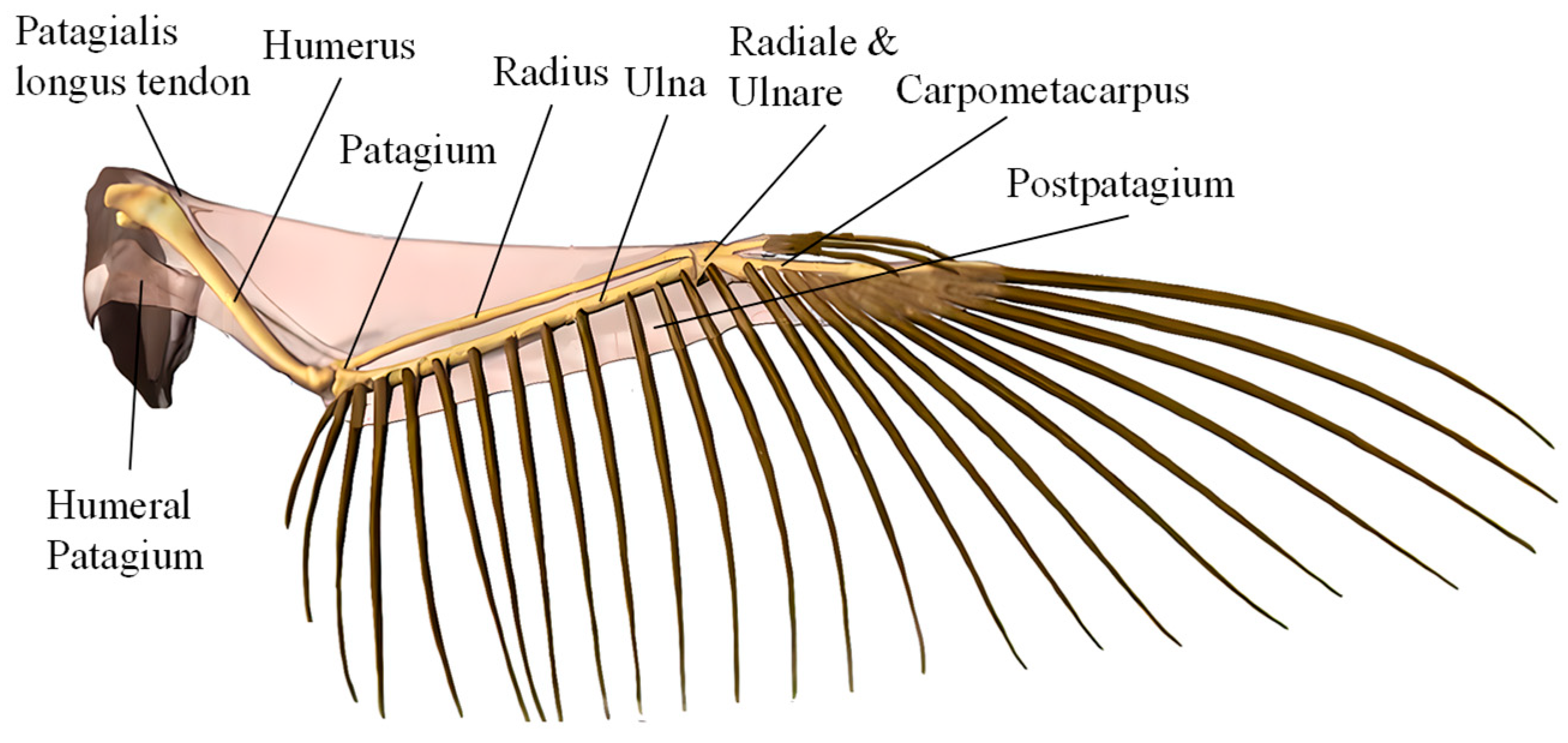
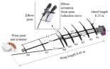
The flapping motion of medium- and large-sized birds involves a combination of flapping, twist, and swing. The wings of birds are primarily composed of bones, muscle tendons encased in wing membranes, and feathers. The wing skeleton consists mainly of the humerus, radius, ulna, and carpal bones [40], as illustrated in Figure 1. Although spanning less than half the wingspan from shoulder to phalanges, this skeleton bears nearly all aerodynamic flight loads. Tendons at the shoulder, elbow, and wrist joints regulate muscle contractions to drive bone movements. The shoulder enables flapping and swinging, while the elbow and wrist primarily drive extension and twisting, respectively, yielding the coordinated ‘flapping–twist–swing’ motion.
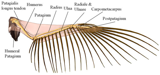
Figure 1.
Wing skeleton structure of large- and medium-sized birds.
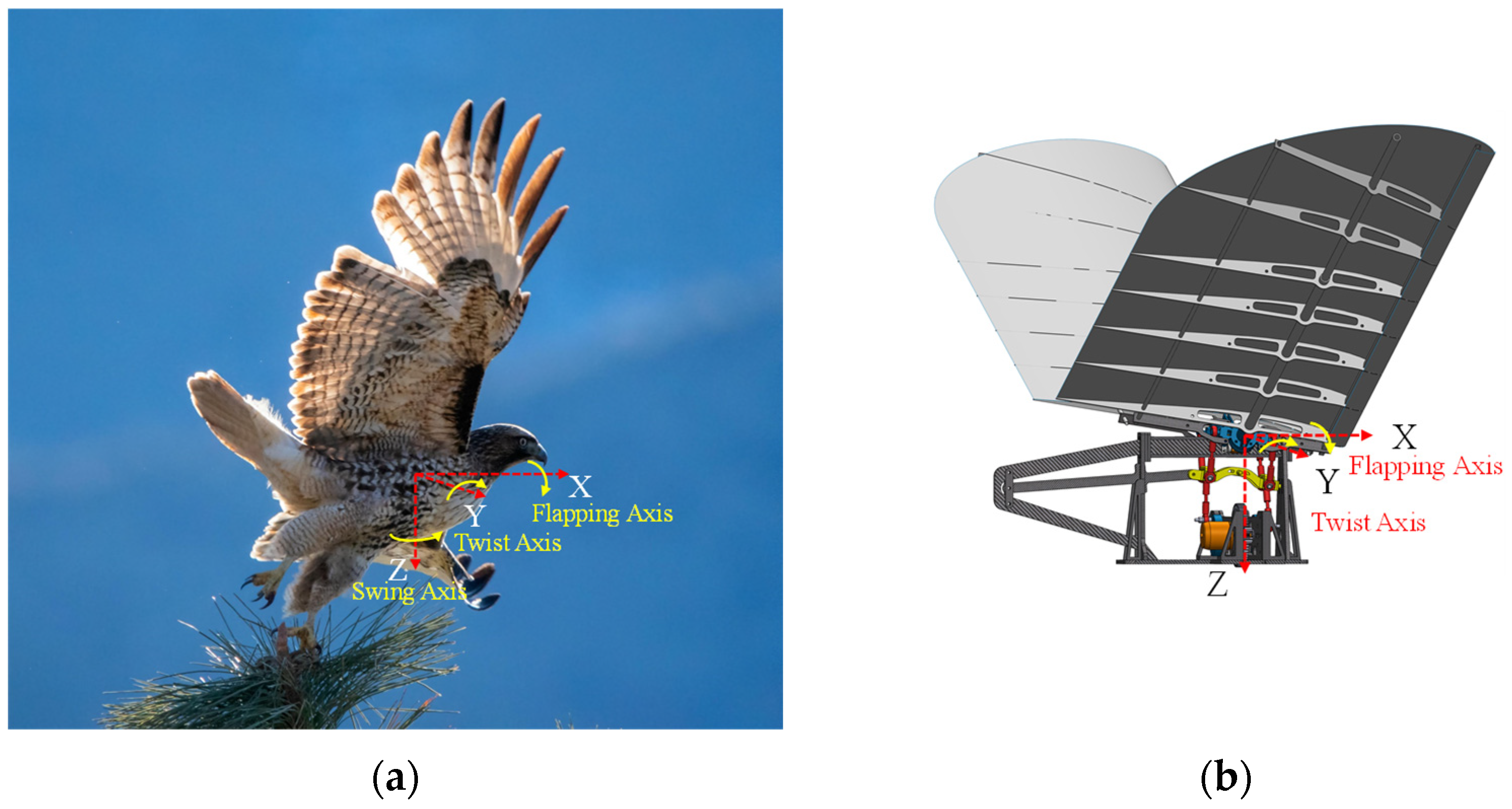
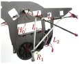
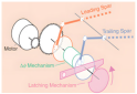
Taking the flight of the red-tailed hawk as an example, as illustrated in Figure 2, the X-Y-Z coordinate system is established at the center of mass. The flapping, swing, and twist motions of the wings about their roots can be represented within this coordinate system.
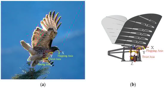
Figure 2.
(a) The flight characteristics of the red-tailed hawk; (b) The flapping–twist coupling mechanism.
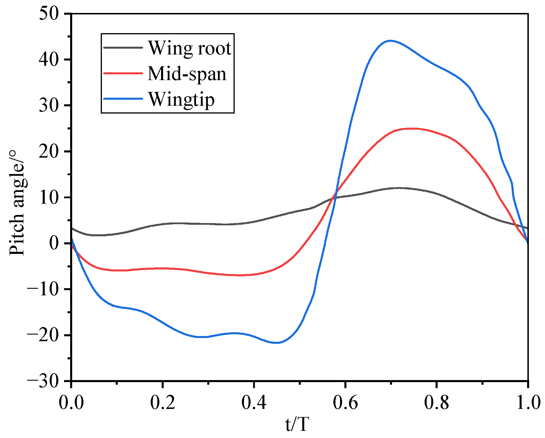
Thomas Wolf and Robert Konrath [11] measured a free-flying barn owl using high-resolution 3D wing shape measurement. Their method parameterizes wing profiles and kinematics during flapping flight, revealing the general relationship between twist amplitudes at spanwise positions (Figure 3). Liu et al. [8] extracted wing kinematics of seagulls, cranes, and geese in horizontal flight from videos, deriving analytical expressions for flapping, twist, and swing laws. The literature indicates that during cruise flight, the flapping, swing, and twist angles of most birds largely follow sinusoidal relationships with established phase differences [41]. Notably, at the mid-position of both upstroke and downstroke, twist and swing amplitudes peak relatively high.
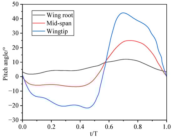
Figure 3.
The variation of twist angle along the spanwise extent in barn owl wings.
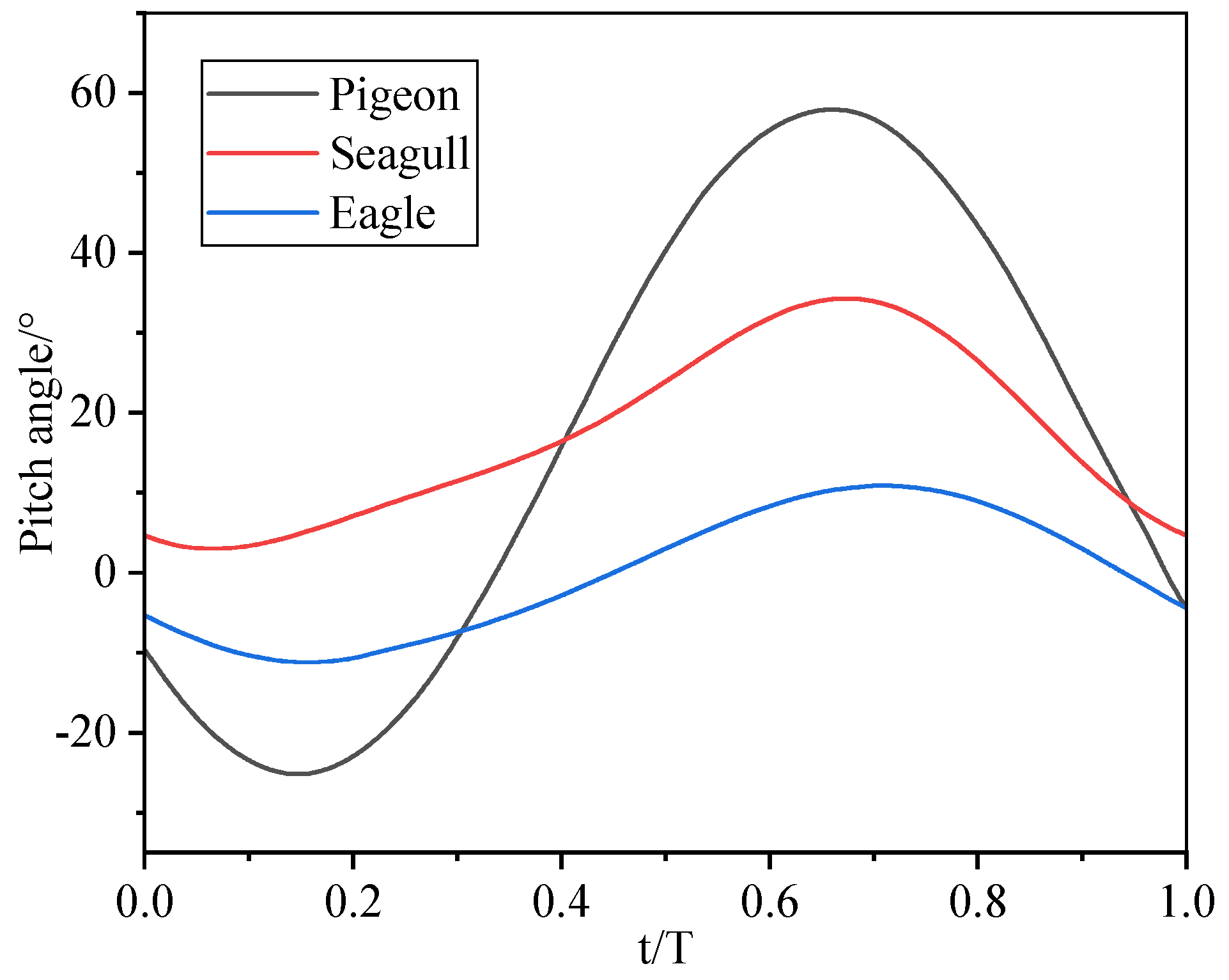
It is advisable to simplify the actual motion patterns of bird wings based on existing technology. For large birds, wing movements can be simplified to two primary motions: shoulder-joint flapping and spanwise–axis twisting, excluding arm-wing and hand-wing folding [41]. Figure 4 illustrates the variation of twist angles during a flapping cycle for a pigeon, a herring gull, and an eagle, while Table 2 presents the body weight, wing span, and twist amplitude of these three bird species [11,30,34].
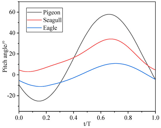
Figure 4.
The variation of twist angle across different bird species.
Table 2.
Parameter comparison among different bird species.
Table 2 data show that during level flight, larger birds correspond to reduced bending and twist amplitudes. For a FWAV sized like the 1.8m-wingspan RoboEagle [23], the design twist amplitude can be set at 0~45°.
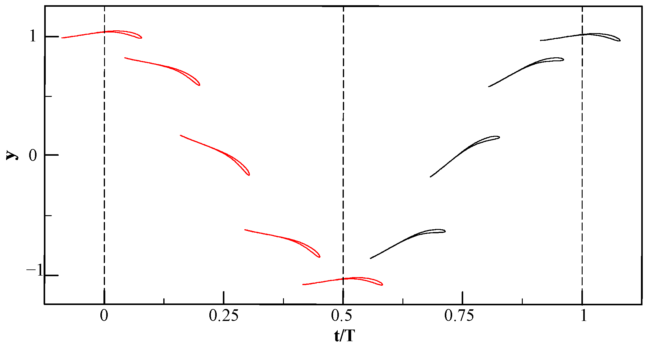
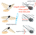
Chordwise stiffness differences between the bird’s arm and hand wings cause flexible deformation in the outer wing, leading to nonlinear twist from root to tip. Asymmetric twist also occurs during upstroke and downstroke. Our analysis focuses solely on flapping-active twist coupling; therefore, the twist mechanism is modeled as symmetric linear twist, as illustrated in Figure 5, with normalized flapping amplitude on the y-axis and maximized wing rigidity as a key constraint.
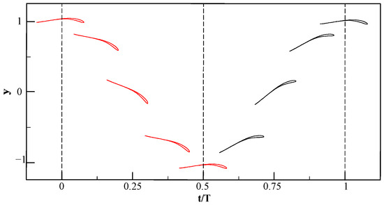
Figure 5.
The motion characteristics of simplified airfoil profiles (The red airfoils in the figure represent the downstroke phase, while the black airfoils indicate the upstroke phase).
Ultimately, bird wing flapping and twisting follow sine and cosine waves. Specifically, the twist angle is zero at the upper and lower stroke limits and peaks near mid-stroke during both upstroke and downstroke [41,42]. This 90-degree phase difference is essential for optimal propulsion efficiency.
2.2. Mechanism Design
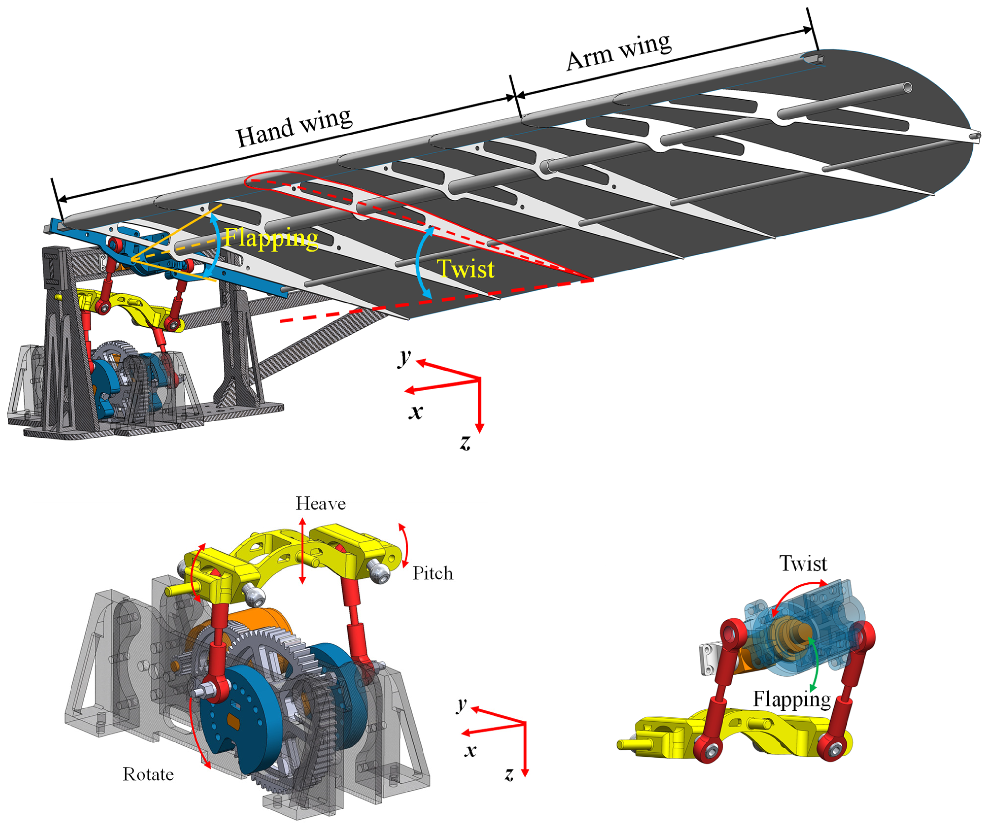
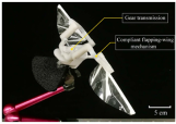
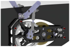
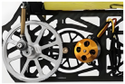
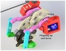
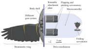
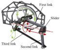
The mechanism comprises three parts (Figure 6), driven by a brushless motor. It drives the crank-link mechanisms on both sides of the reduction group through a two-stage gear reduction. Connecting rods attached to the front and rear cranks connect to a central slider. This slider is mounted to the frame via a revolute joint. Rotation of the front and rear cranks (with a phase difference) causes the slider to translate vertically and twist. Ball joints on the slider connect via rods to rocker arms at the top. A parallelogram linkage drives the rocker arms to flap up and down, while also enabling twisting motion at the outer rod connections. Adjusting the crank radius and front/rear crank phase difference independently modifies the twist amplitude without changing the flapping amplitude. Twist amplitude is defined as the absolute sum of wing rotation angles around the main spar during a flapping cycle (upward pitch during upstroke, downward pitch during downstroke).
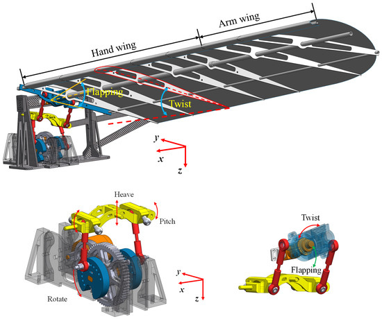
Figure 6.
The flapping mechanism and wing.
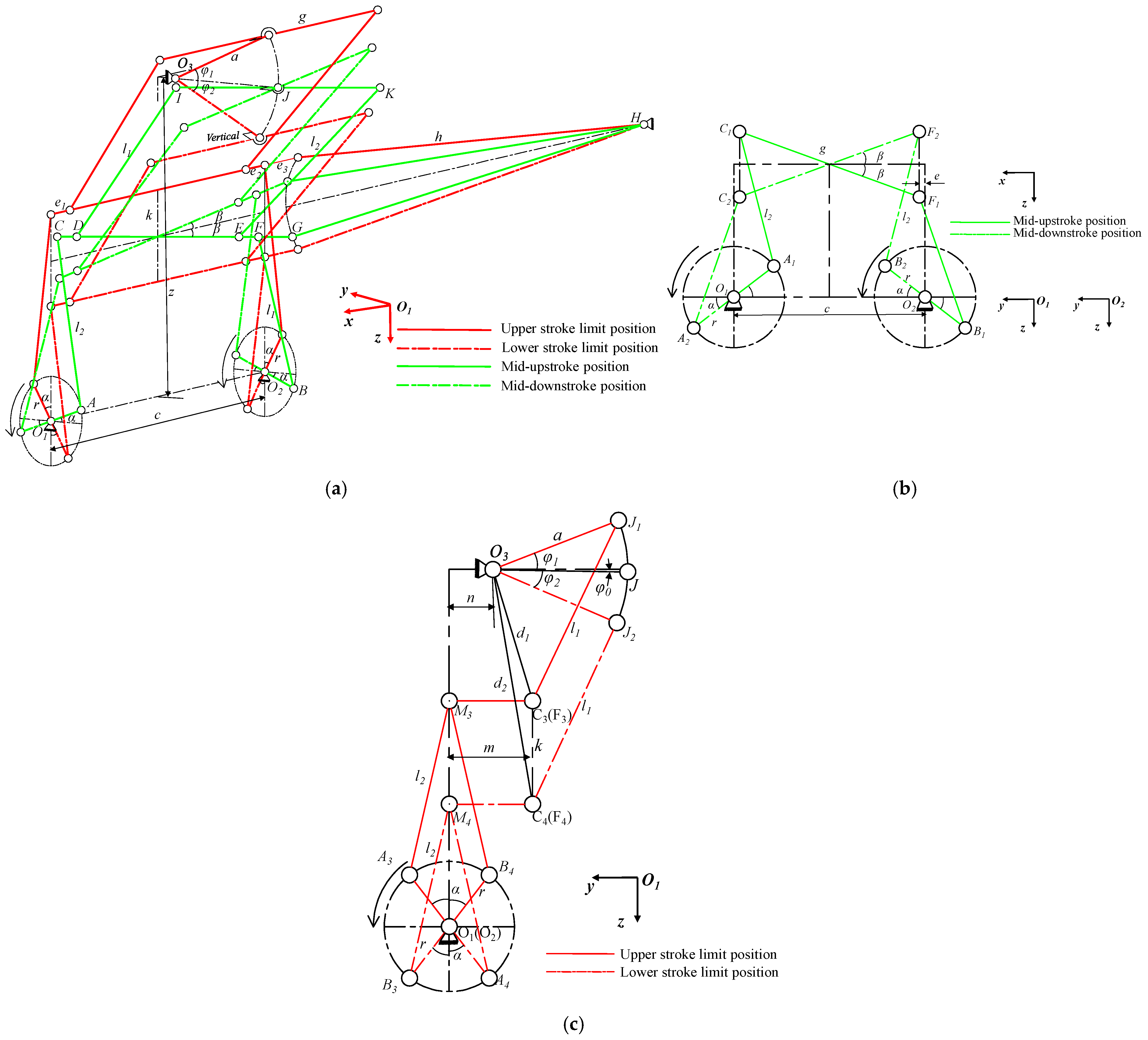
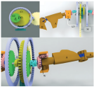
Figure 7a depicts the double-crank slider rocker mechanism which enables the flapping and twist motions. Four curves indicate key flapping phases during one cycle. The reference frame origin O1 is at the driving shaft center on the body. Crank 1 is at O1; Crank 2 is at O2 (shaft end). Vector O1O2 defines the x-axis. The z-axis is vertical (downwards), and the y-axis is perpendicular to the xz-plane (leftwards), forming a right-handed system. Distance O1O2 = e. The wing root is at O3, directly above the O1O2 midpoint, height z above O1O2. Rocker arm O3J length = a. Outer link IK length = g; IK is hinged to O3J and rotates solely about the O3J axis. Upper links DI and EK are equal length; lower slider links CA and FB are also equal length. Slider CG connects to links DI, EK, CA, and FB via spherical joints C, D, E, F, and to the frame via link GH. Both cranks share radius r, with phase difference 2α. Twist amplitude = 2β; flapping amplitudes: upstroke = φ1, downstroke = φ2. Figure 7b,c show the twist and flapping modules, respectively.

Figure 7.
(a) Schematic diagram of mechanism motion; (b) the twist module of the mechanism; (c) the flapping module of the mechanism.
Specific parameter constraints ensure proper flapping mechanism function. The degrees of freedom (DOF) must equal the number of driving sources. This mechanism has one rotational drive, nine moving parts, five revolute pairs, and eight spherical pairs. Thus, its DOF is as follows:
where n represents the number of moving components, P1 denotes the lower pairs, and Pn signifies the higher pairs.
The mechanism follows defined kinematics. Establishing the governing motion equations determines the flapping and twist amplitudes. Points O1, O2, O3, and H are illustrated in Figure 7a, and can be utilized to analyze the motion of the flapping mechanism. Twist amplitude is governed by crank radius and phase difference. Flapping amplitude depends on crank radius, front/rear crank phase difference, and the lengths of the upper links (DI, EK) and rocker arm O3J. Adjusting crank radius and phase difference allows independent variation of twist amplitude (0~45°) while maintaining constant flapping amplitude.
To minimize the overall size of the mechanism, the initial design parameters were set as follows: c = 62 mm, z = 90 mm, n = 11 mm, m = 21 mm, a = 34 mm, and k = 26 mm. Subsequently, derivations can be conducted to establish the relationship between the twist amplitude, the phase angle, and the crank radius.
From Equation (6), we can deduce the twist amplitude.
Based on Equations (2) and (7), the variations of crank radius r, phase angle α, and flapping amplitude can be determined for a specified twist amplitude, as illustrated in Figure 8 below.
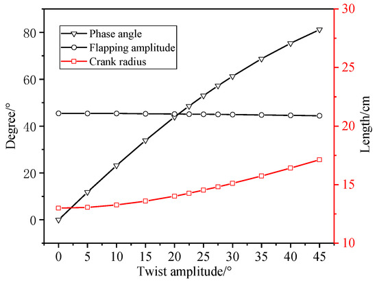
Figure 8.
The variation of crank radius, phase angle and flapping amplitude with twist amplitude.
2.3. Mechanism Simulation Verification
By strategically arranging the hole positions, various combinations of phase angles and crank radii can be achieved, as illustrated in Figure 9.
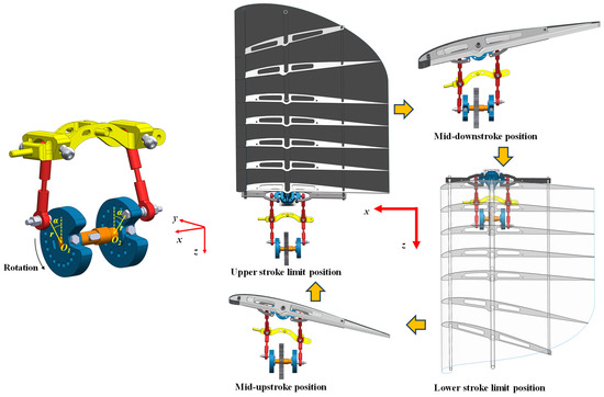
Figure 9.
Schematic diagram of phase difference of double crank installation.
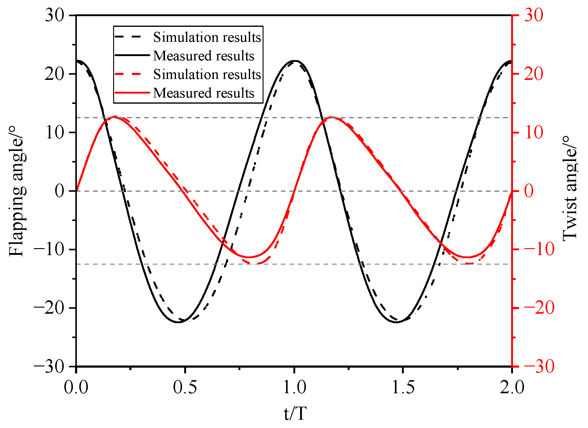
Kinematic analysis yields the variation patterns of the twist angle and flapping angle for amplitudes set to φ = 45° and β = 25°. Figure 10 illustrates the comparison between the simulation results and the actual measurement data; the simulation is performed using the motion simulation module of the SolidWorks software (v2024).
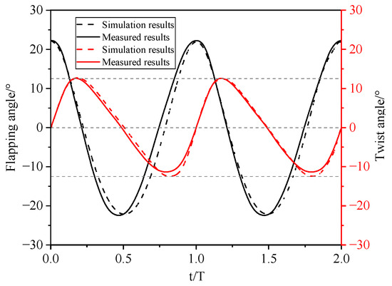
Figure 10.
Comparison of mechanism simulation results and experimental observations.
2.4. Flapping Wing Design
Research [42,43] shows that spanwise twist deformation significantly affects flapping wing thrust. This deformation features progressively increasing twist angles along the span. Wing surface deformation bends ribs and spars, stretching the membrane. Resistance to twist deformation depends on spar/rib configuration, rib count, and membrane material, quantified as wing stiffness. Consequently, the wing’s resistance to spanwise twist is defined by its chordwise bending stiffness EI (E = elastic modulus, I = wing cross-section moment of inertia). Measuring chordwise stiffness at the carbon rod location assesses this stiffness and quantifies the wing’s flexible twist deformation capability [44].
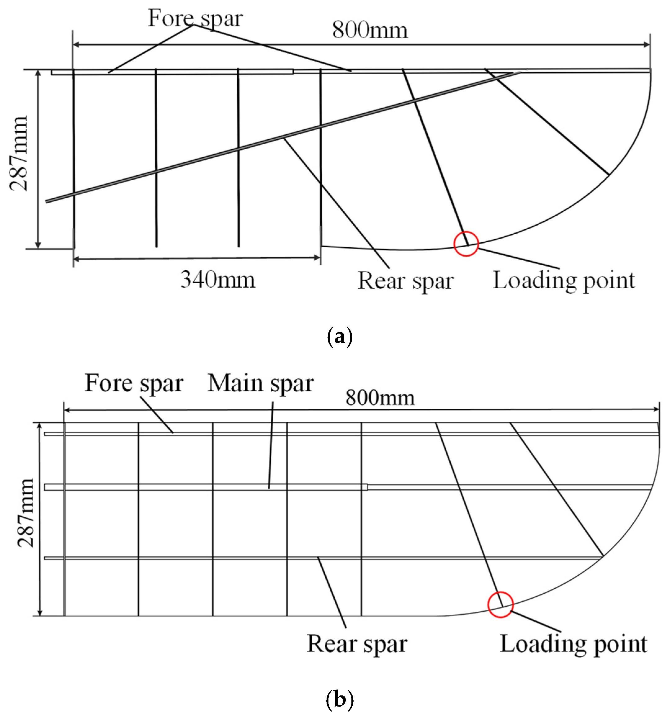
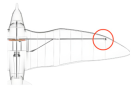
To investigate the impact of active twist, it is essential to minimize the influence of the wing’s inherent twist deformation. In this study, the stiffness of the wing is enhanced by increasing the number of ribs and optimizing the configuration of the wing spars and ribs. A comparison between the RoboEagle’s wing and the newly designed wing is illustrated in Figure 11a,b.

Figure 11.
(a) RoboEagle’s flapping wing. (b) Optimized flapping wing configuration. (The loading point position is marked with a red circle).
Calculating chordwise stiffness assumes linear elasticity. The wing membrane, carbon ribs, and spars exhibit linear elastic behavior: deformation relates linearly to applied force, and the wing restores its shape upon force removal. Satisfying this assumption enables calculating chordwise stiffness using the cantilever beam method (point load at free end) per material mechanics.
Static stiffness k is defined as the slope of the force-displacement curve:
In Equation (8), ΔF represents the change in external force, and ΔD represents the change in displacement, thus the chordwise stiffness EI can be calculated as follows:
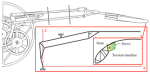
In Equation (9), L is the effective length. For instance, applying force at the trailing edge sets L equal to the local chord length at that point. Analysis shows that membrane deformation transfers to the carbon ribs and spars. Hence, the endpoint of the outer wing section’s trailing-edge second rib (refer to Figure 12) is selected as the stiffness measurement point. The stiffness calculated here defines the flapping wing’s chordwise stiffness.
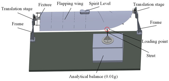
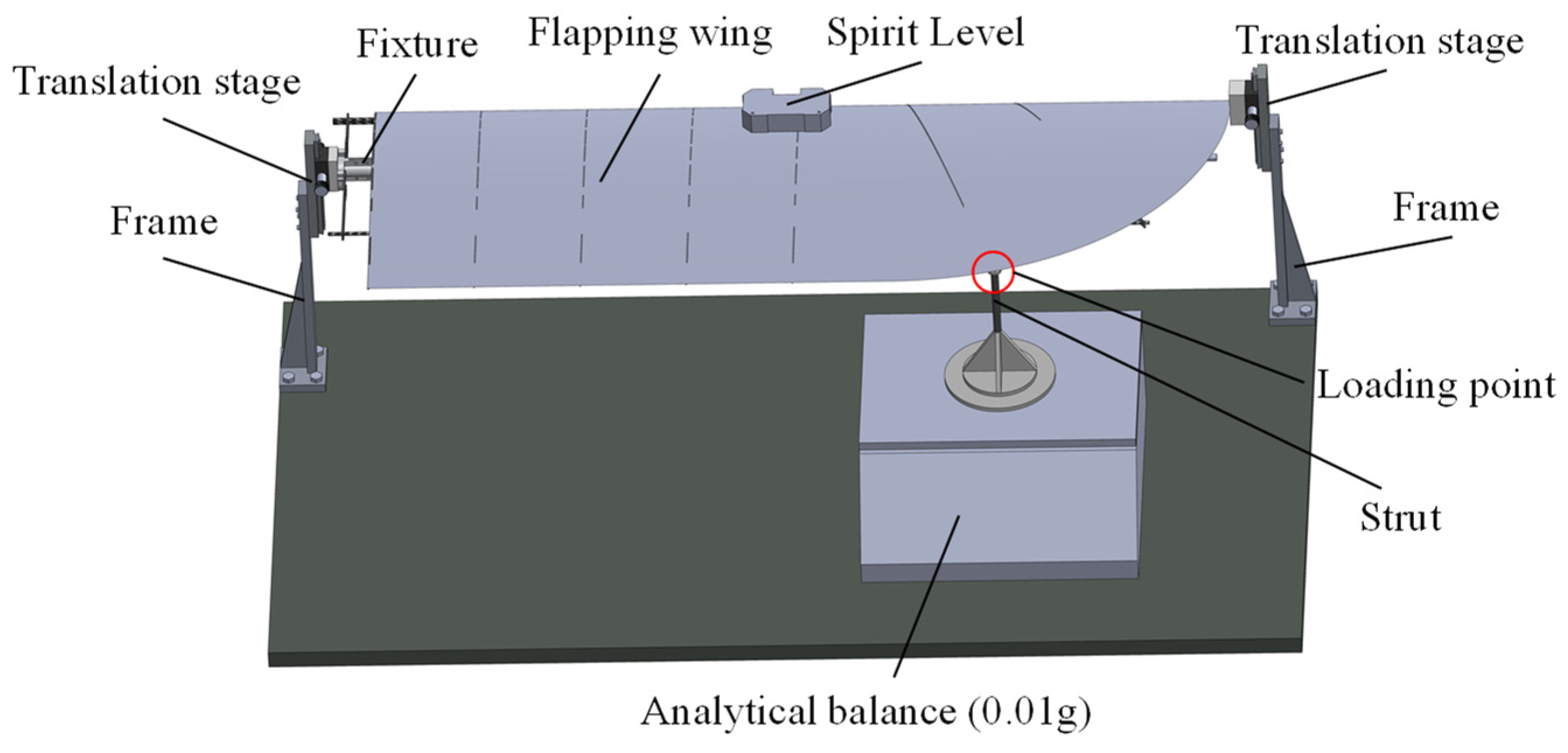
Figure 12.
Schematic diagram of the wing chordwise stiffness measurement device.
To conduct the stiffness measurement process, a chordwise stiffness measurement device is designed for the flapping wing, as illustrated in Figure 12. It comprises an optical table; a z-axis translation stage (accuracy: 0.01 mm) for precise vertical loading point positioning; a wing clamp; a support rod (8 mm diameter carbon rod); and an analytical balance (Zhuojing BSM1.2 kg, accuracy: 0.01 g) measuring the applied load. The translation stage vertically adjusts the loading point for force application. The support rod transfers force: its top contacts the wing, its bottom rests via a base on the balance platform. The balance connects to a computer via serial port for continuous data acquisition.
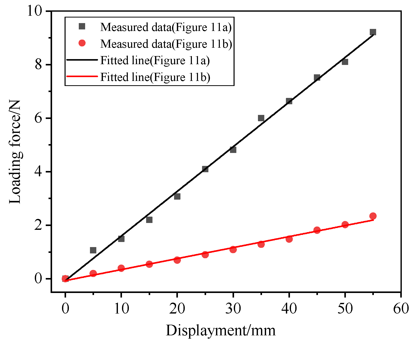
Chordwise stiffness measurement used 5 mm displacement steps until wing deflection exceeded 15% of the effective length. Each load state lasted 30 s; averages were computed from multiple measurements. Linear fitting of deformation data yielded the slope (static stiffness k). Chordwise stiffness EI was then calculated using Equation (9). The final chordwise stiffness EI of the two wings is presented in Figure 13 (EI (Figure 11a)/EI (Figure 11b) = 3.98), which indicates a significant improvement in stiffness.
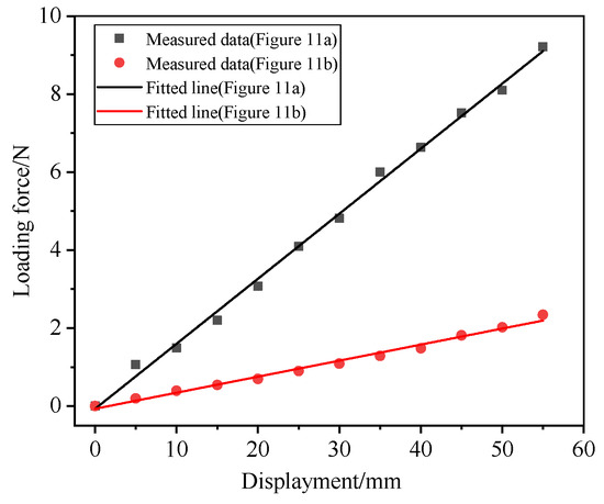
Figure 13.
Comparison of chordwise stiffness test results between Figure 11a,b.
3. Wind Tunnel Experiment
3.1. Experimental Setup
To assess twist amplitude’s effect on lift and thrust under varying conditions, tests centered on the aircraft’s cruise state (angle of attack, airspeed, frequency). The cruise flight state of the RoboEagle is characterized by a flight speed of 8 m/s, and an angle of attack of 8°. Accordingly, wind speeds of 6 and 10 m/s were selected, as they are in proximity to 8 m/s, with angles of attack varying from 0° to 15°. Given the relatively linear variation with angle of attack, the increment was set at 5°. Due to limitations imposed by the structural strength of the mechanism, the flapping frequency was constrained to a range of 1.4 to 2.6 Hz. The twist amplitude was defined from 0° to 45°, with a denser selection around 25°. The combinations of experimental variables are presented in Table 3.
Table 3.
Wind tunnel test parameter settings.
3.2. Wind Tunnel and Other Experimental Devices
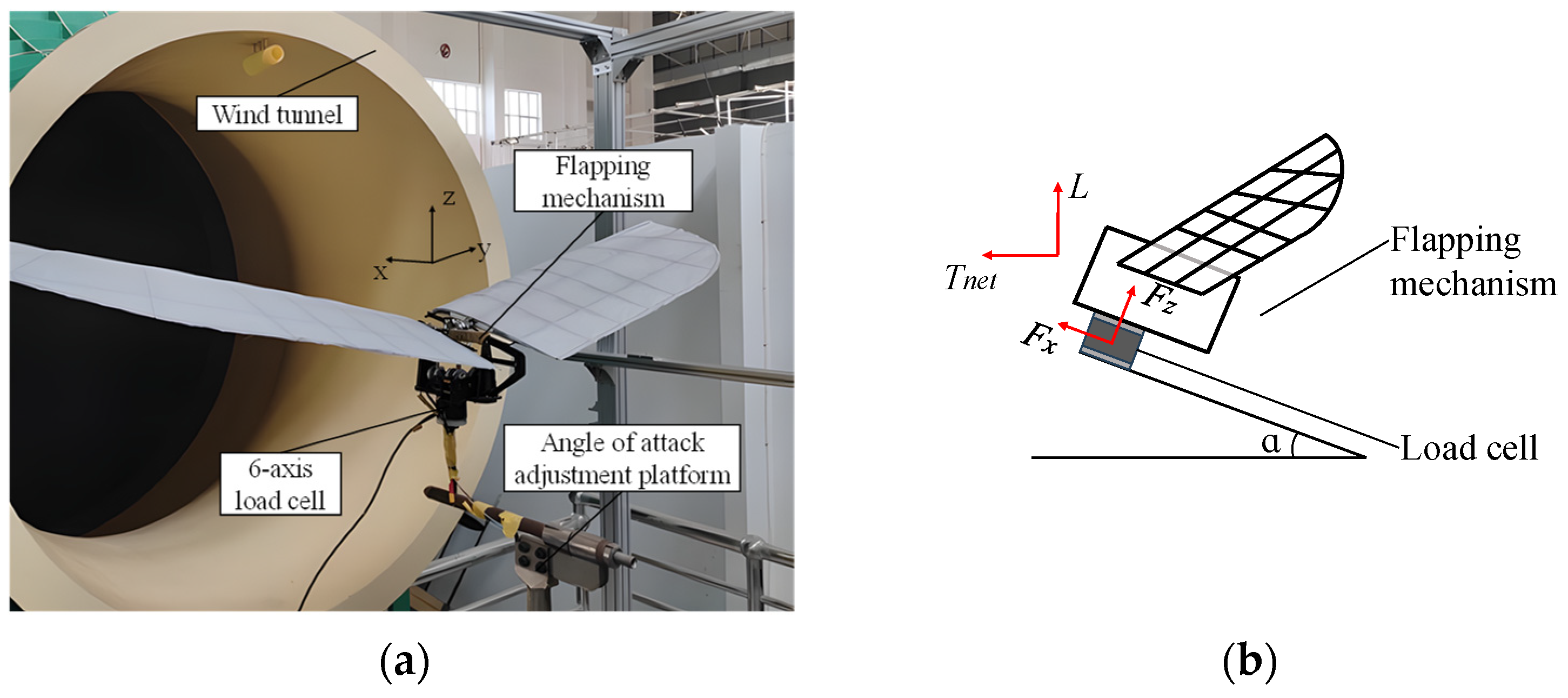
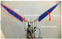
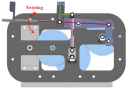
The experiment was conducted in a low-speed open wind tunnel at Northwestern Polytechnical University, where the average turbulence was maintained below 0.5%. The wind speed ranged from 5 to 15 m/s, which is suitable for the flapping mechanism experiments presented in this paper. Figure 14a illustrates the flapping mechanism, flapping wing, and the load cell mounted on the wind tunnel. During the experiment, the K6D40 load cell was employed to measure force featuring a measurement range of ±200 N, a measurement accuracy of 1‰, and a resolution of 1/100 N. The experimental operations and data acquisition were conducted using the FWAV wind tunnel experimental measurement and control system developed by our research group.
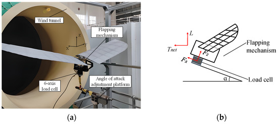
Figure 14.
(a) Force load cell and flapping mechanism installation. (b) Schematic diagram of wind axis and body axis coordinate transformation.
3.3. Data Acquisition and Processing
Given the pronounced periodic unsteady effects of the flapping wing process, it is essential not only to analyze the transient characteristics but also to filter the experimental data and conduct periodic averaging for time-mean analysis. During the experiment, periodic data from the continuous and stable flapping process were collected multiple times. The period of these time-varying data was extracted using the autocorrelation method [7], followed by periodic averaging.
where T is the flapping period, and n is the number of periods.
3.4. Gravity Interference and Axis Transformation
The experimental process is conducted under the condition of no sideslip, with the experimental mechanism mounted on the load cell. The gravitational component of the experimental mechanism and the flapping wing varies with the angle of attack; therefore, it is essential to convert the forces measured in the body axis system by the balance into the forces in the wind axis system. The definitions of these two axis systems are presented in Figure 14b. The transformation of the coordinate axes is as follows:
where Fx is the force measured on the load cell’s x-axis sensor, Fz is the force measured on the load cell’s z-axis sensor, α is the angle of attack, and G is the gravity of the flapping mechanism and the flapping wing; L is the lift, Tnet is the net thrust.
4. Results and Analysis
4.1. Aerodynamic Characteristics
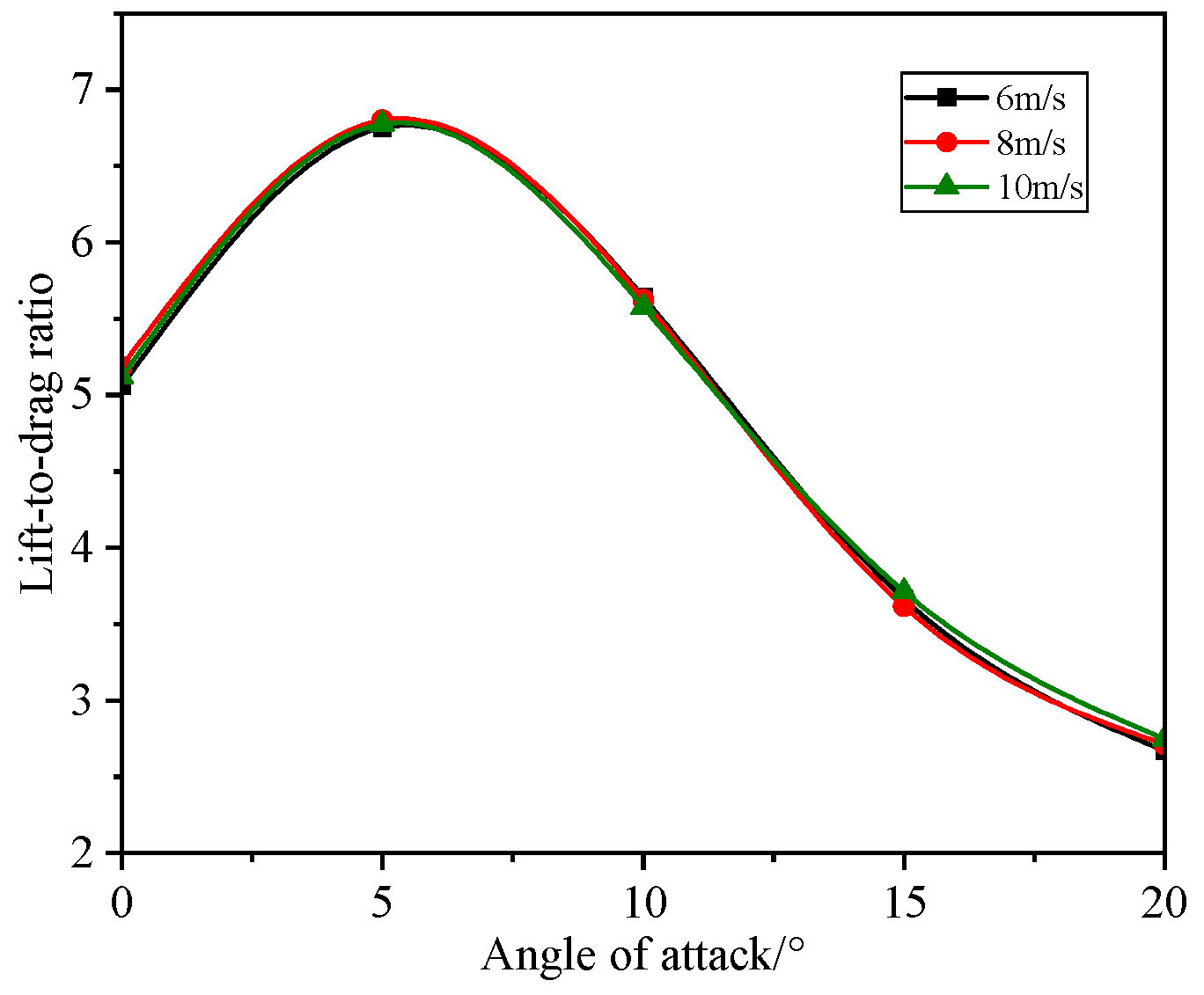
Initially, we investigated the variation trend of the lift-to-drag ratio of the flapping wing concerning the angle of attack under gliding conditions, with both wings positioned horizontally at a wind speed of 8 m/s. The variation trend of the lift-to-drag ratio is illustrated in Figure 15, where it attains a maximum value of 6.8 at an angle of attack of 5°.
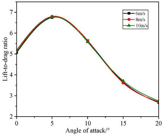
Figure 15.
Variation of lift-to-drag ratio with angle of attack.
4.2. Characteristics of Instantaneous Value Variations
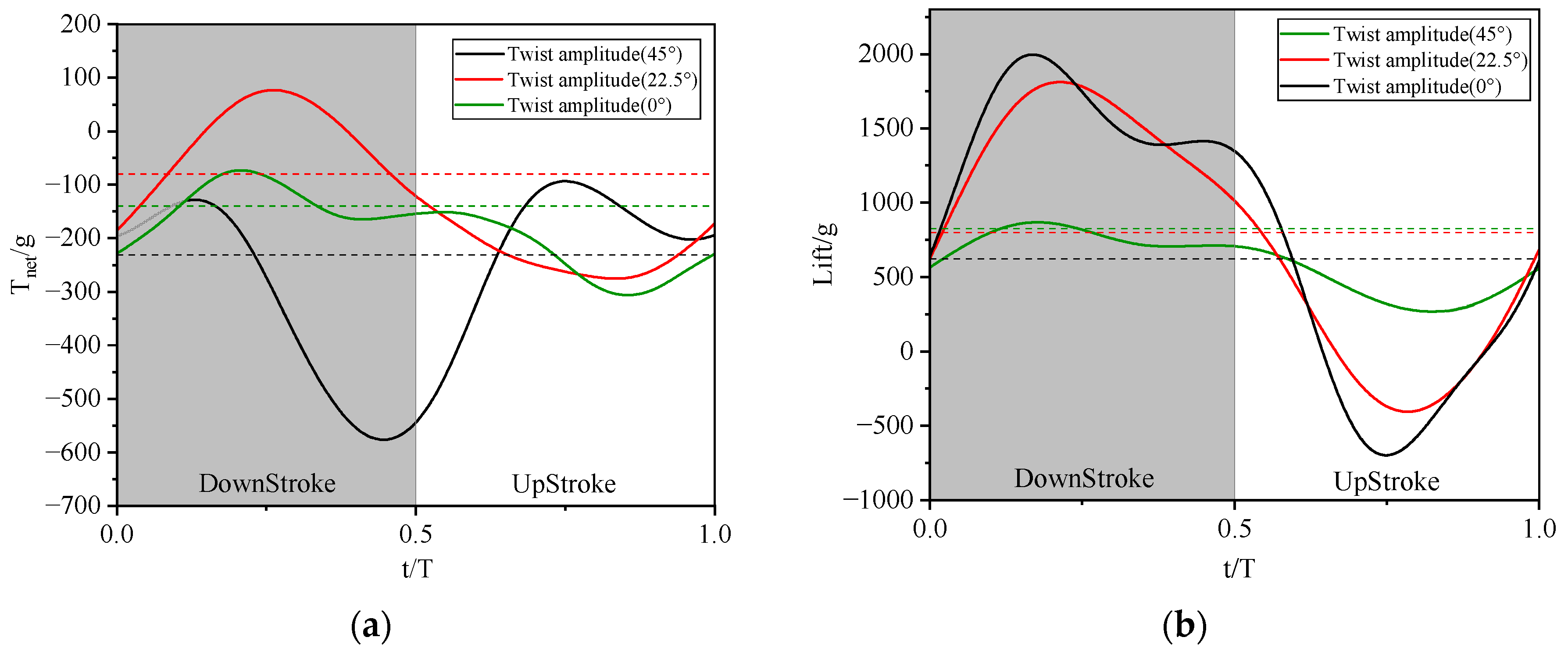
Following the aforementioned experiments, a horizontal comparison of the instantaneous values of lift and net thrust was conducted at twist amplitudes of 0°, 22.5°, and 45°. The experimental conditions selected included a wind speed of 8 m/s, an angle of attack of 5 degrees, and a frequency of 2 Hz. The instantaneous value data were processed using a 5th-order Butterworth filter with a cutoff frequency of 8 Hz. Four flapping cycles were analyzed, with the dashed reference lines in Figure 16 representing the time-averaged values for each twist amplitude condition.
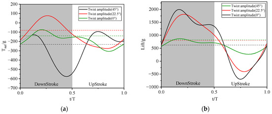
Figure 16.
(a) Net thrust instantaneous value change trend. (b) Lift instantaneous value change trend (The green, red and black dashed lines represent the average lift and thrust forces under corresponding torsion angles, respectively).
Analysis of instantaneous thrust data within a flapping cycle reveals that the 0° and 45° twist amplitude cases exhibit similar thrust variation trends, both featuring two distinct peaks and two troughs. However, the negative thrust peak increases significantly in the 45° twist case, substantially reducing its mean net thrust. In contrast, the 22.5° twist case displays a single peak and trough, achieving a larger positive peak and smaller negative peak compared to the other cases, resulting in superior mean thrust.
For lift, the 0° and 22.5° twist cases show nearly identical variation trends and comparable amplitudes, yielding similar mean lift values. The 45° twist case, however, demonstrates significantly reduced magnitudes for both positive and negative lift peaks, producing the lowest time-averaged lift. Consequently, the instantaneous trends indicate that active twist enhances the peak positive thrust during the upstroke while slightly reducing the peak negative thrust during the downstroke. Regarding lift, active twist reduces both positive and negative peaks during the upstroke and downstroke, with the reduction magnitude proportional to the applied twist amplitude.
Compared to the initial untwisted state, active twist in the second dataset primarily acts during the downstroke, with minimal effect on aerodynamic coefficients during the upstroke. During downstroke, increasing flapping angle coincides with stronger downward (nose-down) twist, lowering the effective angle of attack and reducing peak instantaneous lift. While increased twist reduces the wing surface pressure differential, it also significantly alters the pressure force direction via wing deflection, creating a larger forward thrust component and improving thrust. Overall, optimal active twist increases thrust and reduces peak lift, while maintaining near-unchanged time-averaged lift compared to the untwisted condition, thereby enhancing flapping-wing performance.
4.3. Variation Trend of Lift and Thrust with the Amplitude of Twist
We analyze the variation trends of lift and thrust in relation to the twist amplitude. The frequency is selected within the range of 1.4 to 2.6 Hz, with a wind speed of 8 m/s and an angle of attack of 5°, as illustrated in Figure 17 below.
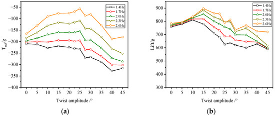
Figure 17.
(a) Variation of net thrust in relation to the twist amplitude. (b) Variation of lift in relation to the twist amplitude.
Data show that, with frequency, angle of attack, and wind speed constant, net thrust first increases then decreases with rising twist amplitude, peaking at 25°. With angle of attack, wind speed, and twist amplitude fixed, net thrust increases with flapping frequency. Lift also peaks with twist amplitude, but at 15°, then gradually decreases between 15° and 22.5°. With constant twist amplitude, lift increases with flapping frequency.
These trends relate to instantaneous value changes. The effective angle of attack, defined as the angle between the airfoil chord and effective incoming flow velocity, decreases with increasing twist amplitude. As effective angle of attack amplitude exceeds 0°, a leading-edge vortex (LEV) forms on the upper surface, creating a low-pressure zone. Near 0°, attached flow occurs over the surface within the dimensionless period, detaching at the trailing edge to form a wake. Below 0°, an LEV develops on the lower surface before detaching. Consequently, rising twist amplitude shifts the LEV from the upper surface to attached flow and then to the lower surface. This transition gradually reduces then reverses the pressure differential across the airfoil, while increased twist amplitude enhances its projection in the thrust direction.
Consequently, the time-averaged pressure differential in the thrust direction first increases, then decreases or reverses, causing thrust to rise initially before falling. Instantaneous lift results from the combined effect of effective angle of attack and incoming flow velocity. Increasing twist amplitude continually reduces the effective angle of attack. Simultaneously, the projection of the pressure differential in the lift direction diminishes, reducing both positive and negative peak lift values. Given the wing’s initial angle of attack, the positive lift peak decreases less than the negative peak, slightly increasing time-averaged lift. However, with further twist increase, the lift-direction projection of the pressure differential drops significantly, causing rapid lift decline.
Comprehensive analysis shows that as twist amplitude rises from 0° to 25°, thrust consistently increases while lift first increases then decreases. For instance, at 2.6 Hz and 22.5° twist, net thrust increases by 10% compared to 15° and by 47% versus no twist, while lift decreases by only 4.46% compared to 15° and increases by 7.8% versus no twist. Thus, the optimal twist amplitude is 22.5°.
4.4. Trends of Lift and Thrust with Wind Speed
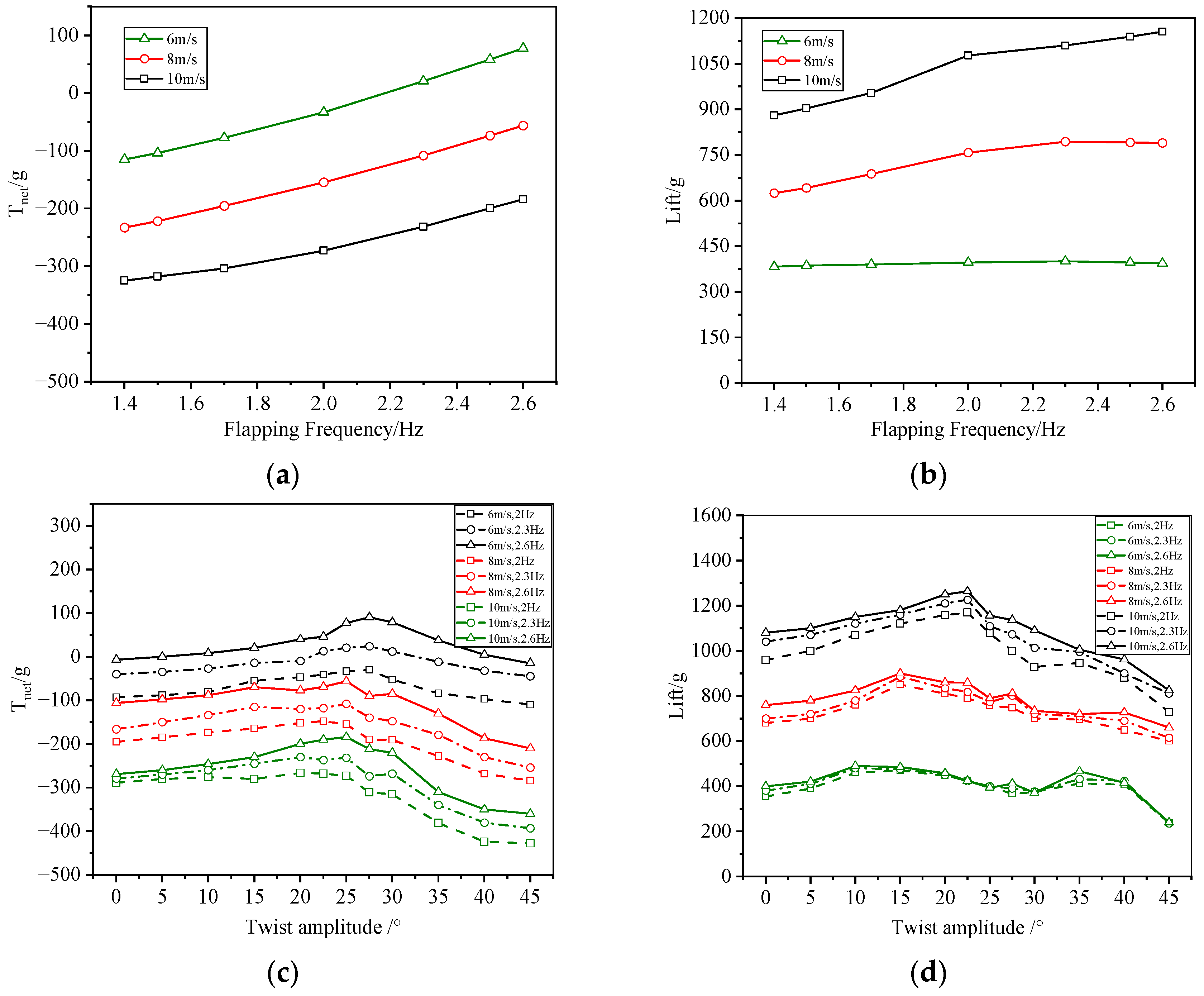
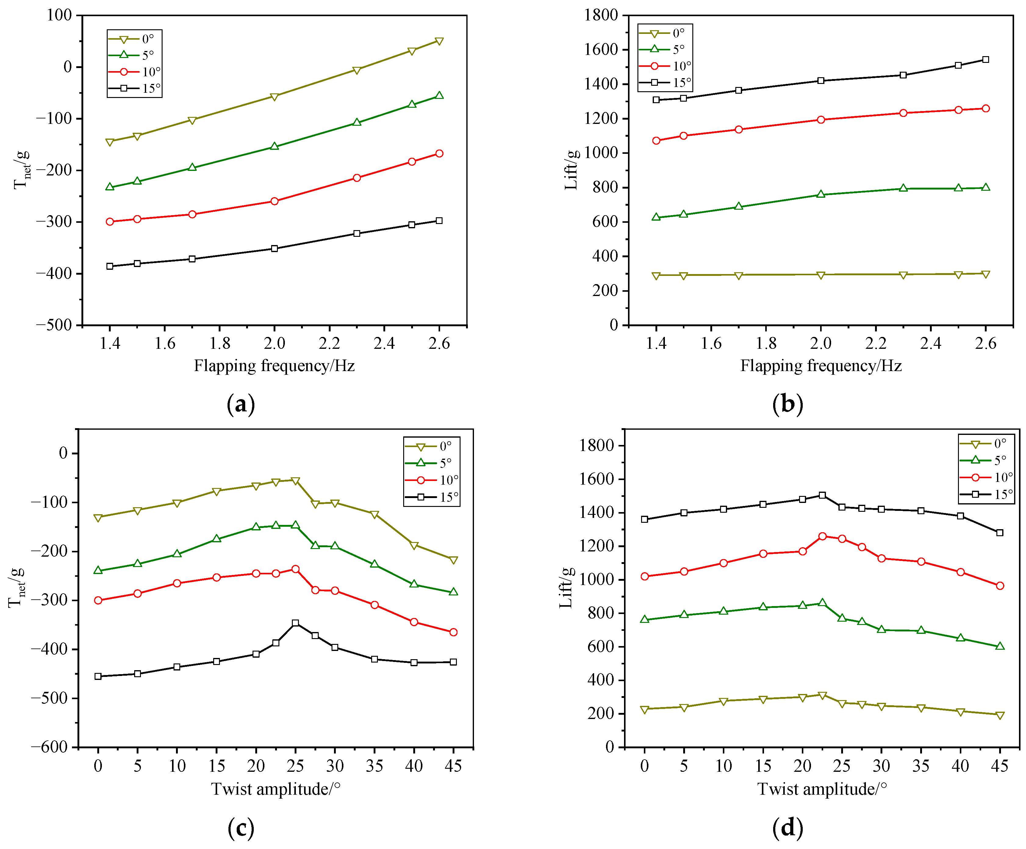
With the angle of attack fixed at 5° and the twist amplitude set at 22.5°, the variations of lift and net thrust under different wind speed conditions, as influenced by varying flapping frequencies, are illustrated in Figure 18 below.
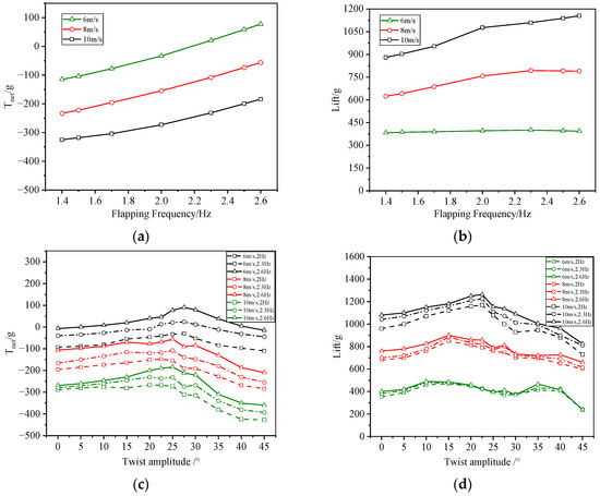
Figure 18.
(a) Net thrust change trend with frequency at different wind speeds. (b) Lift change trend with frequency at different wind speeds. (c) Lift change trend with twist amplitude at different wind speeds. (d) Net thrust change trend with twist amplitude at different wind speeds.
Based on the results presented in Figure 18a,b, it can be concluded that both lift and thrust increase with flapping frequency across varying wind speeds. When the frequency is held constant, lift increases with wind speed; however, net thrust decreases due to a significant increase in drag associated with higher wind speeds. According to Figure 18c,d, it can be concluded that the trend of lift thrust variation with twist amplitude is consistent across different wind speeds. Therefore, the selected optimal twist amplitude demonstrates effective performance at all flight speeds.
4.5. The Trend of Lift and Thrust with Angle of Attack
At a fixed wind speed of 8 m/s and a determined twist amplitude of 22.5°, the trends of lift and thrust at various angles of attack relative to the flapping frequency are illustrated in the figure below.
The results presented in Figure 19a,b indicate that net thrust increases with flapping frequency across various angles of attack. Conversely, lift slightly decreases at a 0° angle of attack but increases with flapping frequency at other angles. When the flapping frequency is held constant, lift increases while net thrust decreases as the angle of attack rises. This phenomenon can be attributed to the significant increase in drag associated with higher angles of attack. From Figure 19c,d, it is evident that at varying angles of attack, lift thrust initially increases and then decreases as twist amplitude increases. Although the trend remains largely similar, the peak positions vary slightly. Overall, the angle of attack does not significantly influence the optimal twist amplitude.
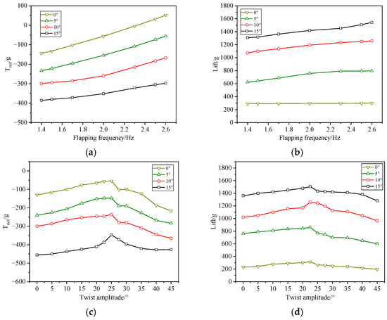
Figure 19.
(a) Net thrust change trend with flapping frequency at different angles of attack. (b) Lift change trend with flapping frequency at different angles of attack. (c) Lift change trend with twist amplitude at different angles of attack. (d) Net thrust change trend with twist amplitude at different angles of attack.
Furthermore, we compared various cruising conditions that maintained closely matched cruise lift at a 5° angle of attack and a wind speed of 6 m/s (i.e., states exhibiting zero net thrust where lift is defined as cruise lift), as summarized in Table 4 below.
Table 4.
Cruising conditions of flapping mechanism.
The data indicate that the flapping frequencies at other twist amplitudes exceed those at the optimal twist amplitude. This suggests that for equivalent cruise lift, the optimal twist amplitude achieves trim at lower flapping frequencies, thereby reducing power consumption; conversely, at comparable flapping frequencies, it facilitates higher cruising speeds, thereby enhancing overall performance.
5. Conclusions
This paper proposes an active flapping–twist coupled wing drive mechanism. By utilizing various crank mounting holes, our mechanism can achieve a twist amplitude ranging from 0° to 45° while maintaining a constant flapping amplitude. The twist amplitude is optimized through this mechanism. Furthermore, we designed and manufactured a rigid flapping wing and conducted wind tunnel experiments to assess the twist parameters. The results indicate that as the twist amplitude increases, the lift of the flapping wing initially exhibits a slight increase, followed by a gradual decrease, and ultimately a rapid decline; conversely, the thrust increases with the twist amplitude, initially rising before decreasing. Consequently, for a rigid flapping wing with a significant wingspan, there exists an optimal twist amplitude that, under consistent conditions of angle of attack, frequency, and wind speed, yields nearly equivalent lift while substantially increasing thrust. This enhancement is advantageous for FWAV, facilitating increased flight speed, enhanced wing loading, and improved payload capacity. Although this design contributes to improved aerodynamic efficiency, it also introduces increased complexity and weight to the mechanism, necessitating further improvements in practicality. It is important to note that the wings of most flapping-wing aircraft are flexible. Our next step involves integrating the overall twist of the wing with the flexible deformation of the outer wing section, enabling the entire wing to achieve optimal nonlinear twist, thereby further optimizing lift and thrust to enhance flight performance.
Author Contributions
Conceptualization, B.S.; formal analysis, R.M.; funding acquisition, Y.Z.; writing—original draft, R.M.; writing—review and editing, J.X. All authors have read and agreed to the published version of the manuscript.
Funding
This work was supported by the Fundamental Research Funds for the Central Universities, and ND Basic Research Funds under Grant G2022WD.
Data Availability Statement
The datasets generated during and/or analyzed during the current study are available from the corresponding author on reasonable request.
Conflicts of Interest
The authors declare no conflicts of interest. The funders had no role in the design of the study, in the collection, analysis, or interpretation of data, in the writing of the manuscript, or in the decision to publish the results.
Abbreviations
The following abbreviations are used in this paper:
| FWAV | Flapping-wing Aerial Vehicle |
| DOF | Degree Of Freedom |
| CFD | Computational Fluid Dynamics |
| LEV | Leading Edge Vortex |
Nomenclature
| α | half of phase angle in the flapping cycle, deg |
| β | half of twist amplitude in the flapping cycle, deg |
| φ | flapping amplitude, deg |
| r | radial dimension, mm |
| Lift | the lift force, g |
| Tnet | the net thrust, g |
| x,y,z | cartesian coordinate system |
| T | flapping period |
| t | time, s |
| E | elastic modulus |
| I | wing moment of inertia |
| EI | chordwise stiffness |
References
- Pornsin-Sirirak, T.N.; Tai, Y.C.; Ho, C.M. Microbat: A palm-sized electrically powered ornithopter. Proc. NASA/JPL Workshop Biomorphic Robot. 2001, 14, 17. [Google Scholar]
- Keennon, M.; Joel, G. Development of two MAVs and vision of the future of MAV design. In Proceedings of the AIAA International Air and Space Symposium and Exposition: The Next 100 Years, Dayton, OH, USA, 14–17 July 2003; p. 2901. [Google Scholar]
- Send, W.; Fischer, M.; Jebens, K.; Mugrauer, R.; Nagarathinam, A.; Scharstein, F. Artificial hinged-wing bird with active twist and partially linear kinematics. In Proceedings of the 28th Congress of the International Council of the Aeronautical Sciences, Brisbane, Australia, 23–28 September 2012; Volume 10, pp. 1–10. [Google Scholar]
- Jiang, H.; Zhou, C.; Xie, P. Design and kinematic analysis of seagull inspired flapping wing robot. In Proceedings of the 2016 IEEE International Conference on Information and Automation (ICIA), Ningbo, China, 1 August 2016; pp. 1382–1386. [Google Scholar]
- Pan, E.; Xu, H.; Yuan, H.; Peng, J.; Xu, W. HIT-Hawk and HIT-Phoenix: Two kinds of flapping-wing flying robotic birds with wingspans beyond 2 meters. Biomim. Intell. Robot. 2021, 1, 100002. [Google Scholar] [CrossRef]
- Pan, E.; Chen, L.; Zhang, B.; Xu, W. A kind of large-sized flapping wing robotic bird: Design and experiments. In Proceedings of the Intelligent Robotics and Applications: 10th International Conference, Proceedings, Part III; Springer: Cham, Switzerland, 2017; Volume 10, pp. 538–550. [Google Scholar]
- Chen, A.; Song, B.; Wang, Z.; Xue, D.; Liu, K. A novel actuation strategy for an agile bioinspired FWAV performing a morphing-coupled wingbeat pattern. IEEE Trans. Robot. 2022, 39, 452–469. [Google Scholar] [CrossRef]
- Liu, T.; Kuykendoll, K.; Rhew, R.; Jones, S. Avian wing geometry and kinematics. AIAA J. 2006, 44, 954–963. [Google Scholar] [CrossRef]
- Tang, D.; Liu, D.; Zhu, H.; Huang, X.; Fan, Z.; Lei, M. Shape reconstructions and morphing kinematics of an eagle during perching manoeuvres. Chin. Phys. B 2020, 29, 024703. [Google Scholar] [CrossRef]
- Beratlis, N.; Capuano, F.; Krishnan, K.; Gurka, R.; Squires, K.; Balaras, E. Direct numerical simulations of a great horn owl in flapping flight. Integr. Comp. Biol. 2020, 60, 1091–1108. [Google Scholar] [CrossRef]
- Wolf, T.; Konrath, R. Avian wing geometry and kinematics of a free-flying barn owl in flapping flight. Exp. Fluids 2015, 56, 28. [Google Scholar] [CrossRef]
- Xie, Y.; Lu, K.; Zhang, D.; Xie, G. Computational analysis of propulsion performance of modified pitching motion airfoils in laminar flow. Math. Probl. Eng. 2014, 1, 420436. [Google Scholar] [CrossRef]
- Ajanic, E.; Paolini, A.; Coster, C.; Floreano, D.; Johansson, C. Robotic avian wing explains aerodynamic advantages of wing folding and stroke tilting in flapping flight. Adv. Intell. Syst. 2023, 5, 2200148. [Google Scholar] [CrossRef]
- Lu, K.; Xie, Y.; Zhang, D. Numerical study of large amplitude, nonsinusoidal motion and camber effects on pitching airfoil propulsion. J. Fluids Struct. 2013, 36, 184–194. [Google Scholar] [CrossRef]
- Yu, M.; Wang, Z.; Hu, H. High fidelity numerical simulation of airfoil thickness and kinematics effects on flapping airfoil propulsion. J. Fluids Struct. 2013, 42, 166–186. [Google Scholar] [CrossRef]
- Lin, S.; Hu, J. Aerodynamic performance study of flapping-wing flow fields. In Proceedings of the 23rd AIAA Applied Aerodynamics Conference, Toronto, ON, Canada, 6–9 June 2005; p. 4611. [Google Scholar]
- Heathcote, S.; Gursul, I. Flexible flapping airfoil propulsion at low Reynolds numbers. AIAA J. 2007, 45, 1066–1079. [Google Scholar] [CrossRef]
- Chang, X.; Zhang, L.; Ma, R.; Wang, N. Numerical investigation on aerodynamic performance of a bionic flapping wing. Appl. Math. Mech. 2019, 40, 1625–1646. [Google Scholar] [CrossRef]
- Han, Y.; Yang, H.; Han, J. Twist-coupled flapping mechanism for bird-type flapping-wing air vehicles. J. Mech. Robot. 2023, 15, 051017. [Google Scholar] [CrossRef]
- Chellapurath, M.; Noble, S.; Sreejalekshmi, K. Design and kinematic analysis of flapping wing mechanism for common swift inspired micro aerial vehicle. Proc. Inst. Mech. Eng. Part C J. Mech. Eng. Sci. 2021, 235, 4026–4036. [Google Scholar] [CrossRef]
- Jiang, S.; Hu, Y.; Li, Q.; Ma, L.; Wang, Y.; Zhou, X.; Liu, Q. Design and analysis of an innovative flapping wing micro aerial vehicle with a figure eight wingtip trajectory. Mech. Sci. 2021, 12, 603–613. [Google Scholar] [CrossRef]
- Ji, B.; Zhu, Q.; Guo, S.; Yang, F.; Li, Y.; Zhu, Z.; Li, Y. Design and experiment of a bionic flapping wing mechanism with flapping–twist–swing motion based on a single rotation. AIP Adv. 2020, 10, 065018. [Google Scholar] [CrossRef]
- Meng, R.; Song, B.; Xuan, J.; Yang, X. Design and verification of a large-scaled flapping-wing aircraft named “cloud owl”. Appl. Sci. 2023, 13, 5667. [Google Scholar] [CrossRef]
- Chung, W. Synthesis of spatial mechanism UR-2SS for path generation. J. Mech. Robot. 2015, 7, 041009. [Google Scholar] [CrossRef]
- Balta, M.; Ahmed, K.; Wang, P.; McCarthy, J.; Taha, H. Design and manufacturing of flapping wing mechanisms for micro air vehicles. In Proceedings of the 58th AIAA/ASCE/AHS/ASC Structures, Structural Dynamics, and Materials Conference, Grapevine, TX, USA, 9–13 January 2017; p. 0509. [Google Scholar]
- Wang, P.; Michael, M. Design of a flapping wing mechanism to coordinate both wing swing and wing pitch. J. Mech. Robot. 2018, 10, 025003. [Google Scholar] [CrossRef]
- Xu, K.; Liu, H. Design of a compliant flapping-wing mechanism with flapping–twist–swing motion. IEEE/ASME Trans. Mechatron. 2022, 27, 5197–5207. [Google Scholar] [CrossRef]
- Zhao, L.; Jiao, Z. Efficiency-optimal rigidity configuration of passive torsional flapping wings. AIAA J. 2021, 59, 4354–4366. [Google Scholar] [CrossRef]
- Fan, X.; Breuer, K.; Vejdani, H. Wing fold and twist greatly improves flight efficiency for bat-scale flapping wing robots. In Proceedings of the 2021 IEEE/RSJ International Conference on Intelligent Robots and Systems (IROS), Prague, Czech Republic, 27 September–1 October 2021; pp. 7391–7397. [Google Scholar]
- Shen, Y.; Zhang, S.; Huang, W.; Shang, C.; Sun, T.; Shi, Q. Characterization of wing kinematics by decoupling joint movement in the pigeon. Biomimetics 2024, 9, 555. [Google Scholar] [CrossRef] [PubMed]
- Kumar, D.; Goyal, T.; Kamle, S.; Mohite, P.; Lau, E. Realisation and testing of novel fully articulated bird-inspired flapping wings for efficient and agile UAVs. Aeronaut. J. 2021, 125, 2114–2148. [Google Scholar] [CrossRef]
- Folkertsma, G.; Straatman, W.; Nijenhuis, N.; Venner, C.; Stramigioli, S. Robird: A robotic bird of prey. IEEE Robot. Autom. Mag. 2017, 24, 22–29. [Google Scholar] [CrossRef]
- Jiang, J.; Zou, W.; Xiong, L.; Ma, H.; Zhou, N.; Zhang, C. Design and Dynamics Analysis of a Flapping-Wing Vehicle with Active Wing Twisting. IEEE/ASME Trans. Mechatron. 2025, 1–11. [Google Scholar] [CrossRef]
- Huang, M. Optimization of flapping wing mechanism of bionic eagle. Proc. Inst. Mech. Eng. Part G J. Aerosp. Eng. 2019, 233, 3260–3272. [Google Scholar] [CrossRef]
- Pu, W.; Shen, Q.; Yang, Y.; Lu, Y.; Yan, Y. Structural Design and Kinematic Modeling of Highly Biomimetic Flapping-Wing Aircraft with Perching Functionality. Biomimetics 2024, 9, 736. [Google Scholar] [CrossRef]
- Wang, Q.; Goosen, J.; Van Keulen, F. An efficient fluid–structure interaction model for optimizing twistable flapping wings. J. Fluids Struct. 2017, 73, 82–99. [Google Scholar] [CrossRef]
- Soto, C.; Bhattacharya, S. The effect of dynamic twisting on the flow field and the unsteady forces of a heaving flat plate. Bioinspiration Biomim. 2023, 18, 026010. [Google Scholar] [CrossRef]
- Wu, Y.; Xie, C.; Meng, Y.; Yang, C. Kinematic optimization of a flexible wing undergoing flapping and pitching. Shock. Vib. 2021, 1, 9635584. [Google Scholar] [CrossRef]
- Gong, C.; Han, J.; Yuan, Z.; Fang, Z.; Chen, G. Numerical investigation of the effects of different parameters on the thrust performance of three-dimensional flapping wings. Aerosp. Sci. Technol. 2019, 84, 431–445. [Google Scholar] [CrossRef]
- Bachmann, T. Anatomical, Morphometrical and Biomechanical Studies of Barn Owls’ and Pigeons’ Wings. Ph.D. Thesis, ARWTH Aachen University, Aachen, Germany, 2010. [Google Scholar]
- Zhao, L.; Shang, Y.; Jiao, Z. A new approach based on undulate propulsion theory for flapping wing analysis and design. In Proceedings of the International Conference on Fluid Power and Mechatronics (FPM), Harbin, China, 5 August 2015; pp. 781–786. [Google Scholar]
- Au, L.; Phan, H.; Park, S.; Park, H. Effect of corrugation on the aerodynamic performance of three-dimensional flapping wings. Aerosp. Sci. Technol. 2020, 105, 106041. [Google Scholar] [CrossRef]
- Zhao, L.; Huang, Q.; Deng, X.; Sane, S. Aerodynamic effects of flexibility in flapping wings. J. R. Soc. Interface 2010, 7, 485–497. [Google Scholar] [CrossRef]
- Xue, D.; Song, B.; Song, W.; Yang, W.; Xu, W.; Wu, T. Computational simulation and free flight validation of body vibration of flapping-wing MAV in forward flight. Aerosp. Sci. Technol. 2019, 95, 105491. [Google Scholar] [CrossRef]


Disclaimer/Publisher’s Note: The statements, opinions and data contained in all publications are solely those of the individual author(s) and contributor(s) and not of MDPI and/or the editor(s). MDPI and/or the editor(s) disclaim responsibility for any injury to people or property resulting from any ideas, methods, instructions or products referred to in the content. |
© 2025 by the authors. Licensee MDPI, Basel, Switzerland. This article is an open access article distributed under the terms and conditions of the Creative Commons Attribution (CC BY) license (https://creativecommons.org/licenses/by/4.0/).