Article

A Low-Cost Experimental Quadcopter Drone Design for Autonomous Search-and-Rescue Missions in GNSS-Denied Environments

Department of Mechanical Engineering, University of Alberta, 9211 116 Street NW, Edmonton, AB T6G 1H9, Canada
*
Author to whom correspondence should be addressed.
These authors contributed equally to this work.
Drones 2025, 9(8), 523; https://doi.org/10.3390/drones9080523
Submission received: 31 May 2025 / Revised: 17 July 2025 / Accepted: 23 July 2025 / Published: 25 July 2025

Abstract

Autonomous drones may be called on to perform search-and-rescue operations in environments without access to signals from the global navigation satellite system (GNSS), such as underground mines, subterranean caverns, or confined tunnels. While technology to perform such missions has been demonstrated at events such as DARPA’s Subterranean (Sub-T) Challenge, the hardware deployed for these missions relies on heavy and expensive sensors, such as LiDAR, carried by costly mobile platforms, such as legged robots and heavy-lift multicopters, creating barriers for deployment and training with this technology for all but the wealthiest search-and-rescue organizations. To address this issue, we have developed a custom four-rotor aerial drone platform specifically built around low-cost low-weight sensors in order to minimize costs and maximize flight time for search-and-rescue operations in GNSS-denied environments. We document the various issues we encountered during the building and testing of the vehicle and how they were solved, for instance a novel redesign of the airframe to handle the aggressive yaw maneuvers commanded by the FUEL exploration framework running onboard the drone. The resulting system is successfully validated through a hardware autonomous flight experiment performed in an underground environment without access to GNSS signals. The contribution of the article is to share our experiences with other groups interested in low-cost search-and-rescue drones to help them advance their own programs.

1. Introduction

Employing drones during search-and-rescue operations is a well-established idea and has been experimentally demonstrated within large-scale research programs such as SHERPA [1] (teams of ground and aerial robots assisting human operators in alpine rescue missions), ICARUS [2] (aerial, ground, and maritime robots assisting first responders in detecting humans within search-and-rescue scenarios), and MOBNET [3] (aerial drones assisting with urban search-and-rescue following natural and man-made disasters).
Drones can be remotely controlled, tele-operated, semi-autonomous, or fully autonomous [4]. To achieve full autonomy, the onboard flight control system (FCS) must be able to perform mission planning and flight operation without human guidance. A key requirement for achieving autonomy is a navigation system, which takes data from onboard instruments, such as global navigation satellite system (GNSS) receivers, altimeters, Inertial Measurement Units (IMUs), Light Detection and Ranging (LiDAR), monocular and stereo cameras, RADAR, and other types [5]. The different sensors all measure a subset of the vehicle’s state (for instance, the GNSS receiver provides position but not attitude data) and are subject to noise and time-varying bias effects. For this reason, navigation systems need to fuse together data from heterogeneous, noisy, and biased filters to extract the vehicle’s position, velocity, and attitude information, most commonly using a Kalman filter. The resulting data is then used by the onboard FCS [6].
A challenge for drone navigation systems is their reliance on signals from the global navigation satellite system (GNSS) [7] to measure the position of the vehicle in a global frame of reference. This becomes problematic when the GNSS signal becomes unavailable, either temporarily due to flying close to obstacles such as tall buildings, canyons, or mountains [8,9,10] or permanently in areas such as underground caves and tunnels [11].
Operating in GNSS-denied environments such as underground mines means the vehicle lacks access to measurements of its absolute position and must therefore estimate this information using data from other sensor types, such as depth cameras or LiDAR, which measure the vehicle’s position relative to its surroundings. The drone’s navigation system must therefore perform simultaneous localization and mapping (SLAM) [12], a solution that is both complicated to implement and difficult to optimize, particularly when using low-cost low-quality sensors or operating in harsh environments, such as poorly lit, dusty, or smoky environments. A recent review article on GNSS-denied navigation is in [13].
In recognition of the importance and difficulties of operating drones autonomously in GNSS-denied environments, the Defense Advanced Research Projects Agency (DARPA) created the Subterranean (SubT) Challenge in 2017, with multi-million-dollar prizes awarded to the winning teams. The goal of the challenge was to spur the development of new technologies to enable autonomous exploration of subterranean environments while providing situational awareness to human operators, a critical capability for search-and-rescue missions such as mine accidents, post-earthquake recovery, or assisting lost or injured spelunkers [14]. The Final Event of this competition was held in September 2021 at the Mega Cavern in Louisville, Kentucky, and required robots to autonomously map and navigate through a large-scale underground environment, with points awarded for localizing specified artifacts, such as human manikins, cell phones, gas sources, and vents of hot air. The first- and second-place winning teams, CERBERUS [15] and Data61 [16], respectively, each deployed a large team of coordinated ground robots and aerial drones to complete this task. While neither team’s budget was publicly released, their choices regarding robot platforms and onboard sensors indicate that substantial costs were incurred. For instance, each of the four-legged robots deployed by team CERBERUS [15] has a list price of USD 150,000. This fact limits access to the technologies that were developed as part of this challenge exclusively to wealthy search-and-rescue organizations.
Cost also limits access to commercially available technologies that can be deployed to perform autonomous search-and-rescue operations in GNSS-denied environments. One example is the Hovermap system developed by Emesent (Brisbane, Australia) [17], a sensing and computing package for drones that provides autonomous navigation, obstacle avoidance, and 3D mapping capabilities, also deployed by team Data61 [16] during the Final Event of the Sub-T Challenge. This system is expensive (USD 70,000) and heavy (1.6 kg), the latter requiring the additional and substantial cost of an industrial heavy-lift aerial drone to carry this payload. Another example is the Skydio (San Mateo, CA, USA) line of drones, capable of autonomous flight in GNSS-denied environments using information from their onboard monocular cameras. This product is also expensive (USD 18,000 for the baseline configuration of the current model), and, since the onboard software is closed-source and does not allow access to all of the drone’s features, the unit cannot be fully customized to meet the specific needs of its search-and-rescue operators.
The motivation for the work presented in the present article was to develop and flight test a low-cost quadcopter aerial drone capable of performing autonomous missions in GNSS-denied environments. This project was a continuation of previous work reported in [18,19,20,21] involving a hexacopter outfitted with a Velodyne (San Jose, CA, USA) Puck LITE LiDAR sensor performing autonomous navigation in GNSS-denied environments using the novel Nonlinear Model Predictive Horizon (NMPH) trajectory planning methodology, which provided efficient computation, dynamic obstacle avoidance capabilities, and generation of smooth flight paths. The NMPH framework was combined with the GBPlanner volumetric graph-based motion planner [22] to obtain a system capable of autonomously navigating through unmapped environments without access to signals from the GNSS. Unfortunately, the high cost of the Velodyne Puck LITE sensor (USD 4600 at the time of purchase) made it by far the most expensive component onboard the drone, while its mass (0.59 kg) limited the flight time and agility of the hexacopter drone vehicle. Motivated by this, we set out to build a new low-cost version of the drone that did not require the use of a Velodyne to perform autonomous exploration of GNSS-denied environments.
The new design employs an order-of-magnitude cheaper and lighter Stereolabs (Paris, France) ZED 2 stereo camera for depth sensing, and replaces the computationally demanding NMPH/GBPlanner combination with the Fast UAV Exploration (FUEL) framework [23] to achieve autonomous navigation. The FUEL system needs only depth images from a stereo camera and employs a frontier-based exploration methodology together with voxel-grid occupancy mapping [23]. The path planner uses a hybrid A* algorithm supplemented with B-splines to generate reference flight trajectories [24]. The new design removes the need for carrying the expensive and heavy Velodyne LiDAR sensor, which reduces the system’s cost while increasing flight time and agility. Since the software onboard the drone is open-source, the system can also be readily customized and does not require any kind of licensing payment from its users.
The contributions of this article are to provide the technical details of our work, highlighting our design decisions and discussing the problems we faced and how we solved them. For instance, we found that the FUEL system would command aggressive yaw trajectories during flight in order to compensate for the limited field of view of the stereo camera but that such maneuvers created large drops in altitude of the drone vehicle, risking a hard impact with the ground and a subsequent crash. This issue was resolved by manufacturing twisted rotor arms, which increased the available yaw control effort, a novel solution that, to the best of our knowledge, has not been used for any other drones employing FUEL. We also present and analyze the results of a full-scale autonomous exploration flight experiment of our hardware system in a GNSS-denied environment. We hope that sharing this information allows other groups interested in low-cost search-and-rescue operations in GNSS-denied environments to reproduce our work and use it to advance their own efforts.
The remainder of this paper is structured as follows. Section 2 reviews other published works in the area of experimentally validated search-and-rescue operations using autonomous drones in GNSS-denied environments. Section 3 covers the details of our proposed design, describing the hardware and software and the iterations undertaken after the initial flight test experiments. Section 4 describes the results of a successful full-scale hardware flight experiment conducted in a large GNSS-denied environment. Finally, Section 5 summarizes our findings and suggests directions for future work.

2. Related Works

A 2020 article [25] considers a search-and-rescue scenario conducted under the canopies of trees, where signals from the GNSS cannot be received. The system relies on multiple aerial drones outfitted with Hokuyo 2D LiDAR scanners, which are combined to create an occupancy map of the environment. Scans from the different vehicles are then communicated to an offboard laptop computer, which constructs a globally consistent map. The main limitations of this work are its reliance on active communication with a ground station to establish a globally consistent map and the 2D nature of the resulting map reducing the ability for the system to navigate around obstacles.
In [26], the authors present an autonomous quadrotor designed for conducting search-and-rescue operations in GNSS-denied environments following disasters. Their aerial drone is built on a DJI Matrice 210 V2 airframe outfitted with an Ouster OS-0 LiDAR, a FLIR AGX thermal camera, and two Intel RealSense D455 RGB-D cameras. Under two experimentally simulated disaster scenarios, the platform was demonstrated to provide useful additional information to tele-operators of tracked ground vehicles, and could perform in GNSS-denied environments while achieving obstacle avoidance. Although the system performed well and demonstrated its utility for search-and-rescue scenarios, an unstated drawback is the reliance of the system on a LiDAR sensor (USD 7000) and a commercial drone platform (USD 10,000), reducing its accessibility for search-and-rescue groups in terms of both upfront cost as well as those associated with repair in case of a crash.
The article in [27] presents a software framework designed for operating aerial drones in subterranean search-and-rescue missions, which was deployed in the DARPA Sub-T Challenge described in Section 1 by the NASA–JPL team CoSTAR. The system is run onboard a custom-built quadrotor drone and relies on a Velodyne Puck LITE LiDAR sensor to perform sensing and navigation using the LIO–SLAM [28] LiDAR–Inertial odometry package for state estimation and the Motion Primitives-Based Path Planner (MBP) package [29] for path planning. The limitations of the drone design are its reliance on the high-cost Velodyne LiDAR sensor to obtain sufficiently high-quality 3D point clouds of the environment, whose mass is acknowledged by the authors to limit the useful flight time of the drone.
In [30], the authors cover a system consisting of teams of drone robots collaborating with a human first responder inside a GNSS-denied environment to perform search-and-rescue missions. The human operator carries a hand-held interface device used to command a team of aerial drones to either reach a specified waypoint or follow the operator, and the aerial drones are then responsible for autonomously carrying out their assigned goal while avoiding static and dynamic obstacles. Each drone employs four pairs of coaxial rotors and carries an Ouster OS-1 32 LiDAR used for mapping and pose estimation, an Intel D435i RGB-D camera used to identify and range human casualties in the drone’s field of view, and an ultra-wide-band (UWB) transceiver used to keep the drones at safe distances from each other. The drawbacks of this system are the high costs of the drones (for instance, each onboard LiDAR sensor has a cost of USD 8000), as well as the inability to autonomously explore the environment unless waypoints are first assigned by the human operator.
Perhaps the closest article to our presented work is [31], which documents the design details of two quadrotor aerial drones intended for search-and-rescue operations within GNSS-denied environments. Unlike the previous references, the drone does not rely on LiDAR, instead using an Intel Realsense T265 stereo camera running an onboard visual SLAM to estimate the pose of the vehicle, an Intel Realsense D435i camera to obtain RGB-D point clouds, and a Terabee TeraRanger laser altimeter. The search drone employs a combination of RTabMAP [32] to build 3D maps of the environment and YOLOv3 [33] to locate humans within the built-up map. Once such a detection occurs, the drone flies back to its starting point, where it relays its information to a rescue drone, which in turn navigates to the located survivor’s location with a payload. One limitation of this system is its inability to autonomously explore the unknown environment. The search drone must be navigated from the ground station by the human operator, who actively specifies waypoints within the map being built up. A second limitation is the reliance on the T265 stereo camera for pose information, which risks losing track of its pose, with one such instance illustrated within the article. This matches up with our own experiences with the T265 unit in the early stages of our research program, leading us to drop this particular unit from the onboard sensor suite.

3. Description of Design

3.1. Hardware

An aerial drone consists of an airframe, thrust sources, and a flight control system (FCS) [34]. The airframe design is determined by the mission profile, but common configurations include fixed-wing, multi-rotor, and hybrid [35]. The thrust sources are spinning propellers, powered either by an internal combustion engine or an electric motor [36]. The FCS typically consists of a microcontroller running the low-level vehicle stabilization control loops and a single-board computer running the high-level path planning and environmental perception algorithms. The drone designers must consider a variety of factors, including payload capacity, choice of sensors, required computing power, desired flight time, agility and maneuverability requirements, and cost. This requires analyzing material selection, aerodynamic effects, environmental conditions, power requirements, and safety considerations.
The drone design for our project is shown in Figure 1. The hardware components of this system are listed in Table 1.
The airframe is the FlameWheel 450 from DJI (Shenzhen, China). This kit provides a set of four rotor arms sandwiched between a top and bottom mounting plate. The tip of each arm carries a brushless motor that drives a propeller and is supplied by current from an electronic speed controller. As seen in Figure 1, a set of landing gear skids, propeller guards, and a 3D-printed stereo camera mount are also incorporated into the airframe. The mass of the quadcopter vehicle equipped with all the components listed in Table 1 is 2.3 kg. As illustrated in Figure 2, the quadcopter uses an X-frame shape, with the vehicle’s forward heading direction aligned between the two front propeller arms.
The low-level flight control functions are handled by the Pixhawk 5X flight controller from Holybro (Shenzhen, China). This unit runs the FMUv5X open firmware, employing a 32-Bit Arm Cortex-M7 at 216 MHz for the vehicle stabilization control loops and a 32-Bit Arm Cortex-M3 running at 24 MHz for processing data from external sensors. The Pixhawk 5X module also carries redundant IMUs and barometers to ensure robust sensing capability. Using Ardupilot v4.3.0 and a ground station running the popular QGroundControl v4.2.6 software, users can interface with the onboard flight control system in real time. The onboard IMUs are used to estimate the vehicle’s position, orientation, and inertial and altitude information. However, since the onboard IMUs exhibit significant noise and bias effects, the resulting estimates have poor accuracy, particularly the position. A key feature of the Pixhawk 5X platform is the ability of the onboard extended Kalman filter (EKF)-based state estimator software to employ aiding measurements from additional sensors, such as GNSS receivers, or pose measurement systems to improve the quality of the estimates of the vehicle’s pose. This will play an important part in Section 3.2.

3.2. Environmental Perception

The depth image sensor installed on our quadcopter is the ZED 2 stereo camera from Stereolabs (Paris, France). This system can provide 662 × 366 resolution depth maps with a 120° field of view, a maximum range of 20 m, and frame rates up to 100 Hz. The depth image is obtained by cross-correlation of pixels between the left and right camera views, which is performed by a software development kit (SDK) v3.8 running separately from the camera, meaning the rate of depth images is determined by the computational power available onboard the drone.
Because the stereo camera is the sole source of environmental perception for the drone, the system’s performance relies on obtaining good visual data. One challenge would be flying through dim or completely dark environments, leading to poor cross-correlation of pixels and degrading the output depth image, potentially causing a complete failure of the system. A practical and inexpensive solution to this issue is adding an onboard light source to illuminate the environment ahead of the drone, a solution deployed by several of the teams participating in the Sub-T Final Event [14] previously mentioned in Section 1. A different failure mode involves featureless surfaces such as uniform walls, which would also prevent the stereo camera from computing a cross-correlation between the left and right views. In practice, we did not face either of these issues within our flight test environment described in Section 4.
The stereo SLAM algorithm implemented within the ZED 2’s SDK provides estimates of the vehicle’s position and attitude, which are used as aiding measurements for the Pixhawk 5X’s state estimator. This integration enables the quadcopter to execute specified flight trajectories in GNSS-denied environments. However, in preliminary hardware testing, the drone was found to suffer from the following issue: whenever the drone would pitch down in order to travel forward, the estimates from the stereo SLAM algorithm falsely indicated displacement along the vertical, causing the vehicle to drift upwards during its motion. This is visually illustrated in Figure 3. This effect was mirrored when the vehicle would pitch up to travel backwards.
Initial attempts to rectify the vertical drift using altitude information from the Pixhawk 5X’s barometers proved to be unsuccessful. As a result, a Garmin (Olathe, KS, USA) LiDAR-Lite v3 was integrated into the drone’s airframe for altitude measurements. This laser-based sensor provides altitude information with a precision of ±2.5 cm at a rate of 500 Hz. The end result of this change was the complete elimination of the vertical drift effects observed in the initial hardware flights.
We later realized the false readings from the stereo SLAM algorithm onboard the camera would also affect estimates along the longitudinal axis of the drone, an effect that was not visually observable during our preliminary flight testing. In practice, the full-scale experiment documented in Section 4 was not subject to this error since it used limited speeds, which avoided the need for large pitch angles that are used in fast forward flight. A more elegant solution for this issue would be the integration of the vehicle’s estimated attitude into the stereo SLAM algorithm, making it accurate within any flight regime.

3.3. Path Planning

The high-level flight planning was handled by the software architecture illustrated in Figure 4, running onboard the drone’s NVIDIA (Santa Clara, CA, USA) Jetson Xavier NX single-board computer.
In order to perform autonomous navigation in GNSS-denied environments, the FUEL system from [23] provides both global exploration and flight path planning capabilities. The schematic for this algorithm is illustrated in Figure 5.
The drone’s environment is represented as a 3D voxel grid map, using a Euclidean Signed Distance Field to encode its geometry. Voxels are classified into one of three possible types: occupied, unoccupied, and unexplored. The classical strategy of frontier-based exploration [37] is used to guide the vehicle to investigate unknown boundaries and spaces of its environment. Frontiers are identified as clusters of unexplored voxels adjacent to clusters of unoccupied voxels. Traditionally, the centroid of the cluster of unexplored voxels would be assigned as a waypoint for the navigation system. To make exploration more efficient, FUEL [23] first generates a set of viewpoints of the cluster from different angles, then selects the one that provides the least-obstructed view of the unexplored cluster. The set of identified frontier clusters and their associated viewpoint angles are used to plan a global tour passing through all of them. This is conducted by casting the exploration as a modified asymmetric traveling salesman problem [38], which can be solved efficiently. This global tour is actively updated as new frontiers are found, leading to a complete exploration of the drone’s environment.
Information from the global tour is used to generate local trajectories using the methodology in [24]. A set of local motion primitives for the drone vehicle are generated, pruned to remove redundancies, and then validated for feasibility within the current voxel grid map. A hybrid A* search is run to assemble a local trajectory that minimizes flight time and actuator inputs, also employing a heuristic function to speed up the search. The resulting path is then optimized by using its edges as the control points of a B-spline. The convex hull property of B-splines is used to validate whether the velocity and acceleration profiles of the optimized local trajectory are within prescribed limits and whether the path provides sufficient clearance from occupied voxels within the grid map. If the proposed trajectory is found to be unacceptable, the system verifies if another candidate local trajectory is available. If yes, another optimization is performed; if not, the algorithm terminates, signaling the drone to land at its current position. This is a failure mode of the path planning algorithm; however, we did not encounter it during our experimental flight testing described in Section 4.

3.4. Rotor Arm Redesign

During our flight experiments, it was observed that the exploration algorithm commanded trajectories with aggressive yaw in order to compensate for the limited field of view of the stereo camera depth sensor. A yaw maneuver requires creating an imbalance between the clockwise and counter-clockwise rotor torques, which is achieved by reducing the angular speed of two opposing motors. However, a by-product of this is a reduction in thrust, causing a temporary drop in altitude of the vehicle.
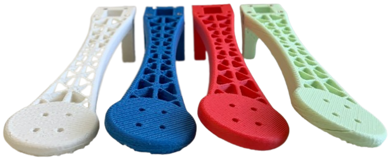
To address this issue, the geometry of the drone was modified in order to change the ratio between maximum thrust and counter-torque. A twist angle was introduced into each of the rotor arms, as seen in the 3D-printed members shown in Figure 6. This twist redistributes vertical thrust in order to increase the maximum torque that can be generated on the vehicle while only slightly decreasing the maximum thrust that can be generated.
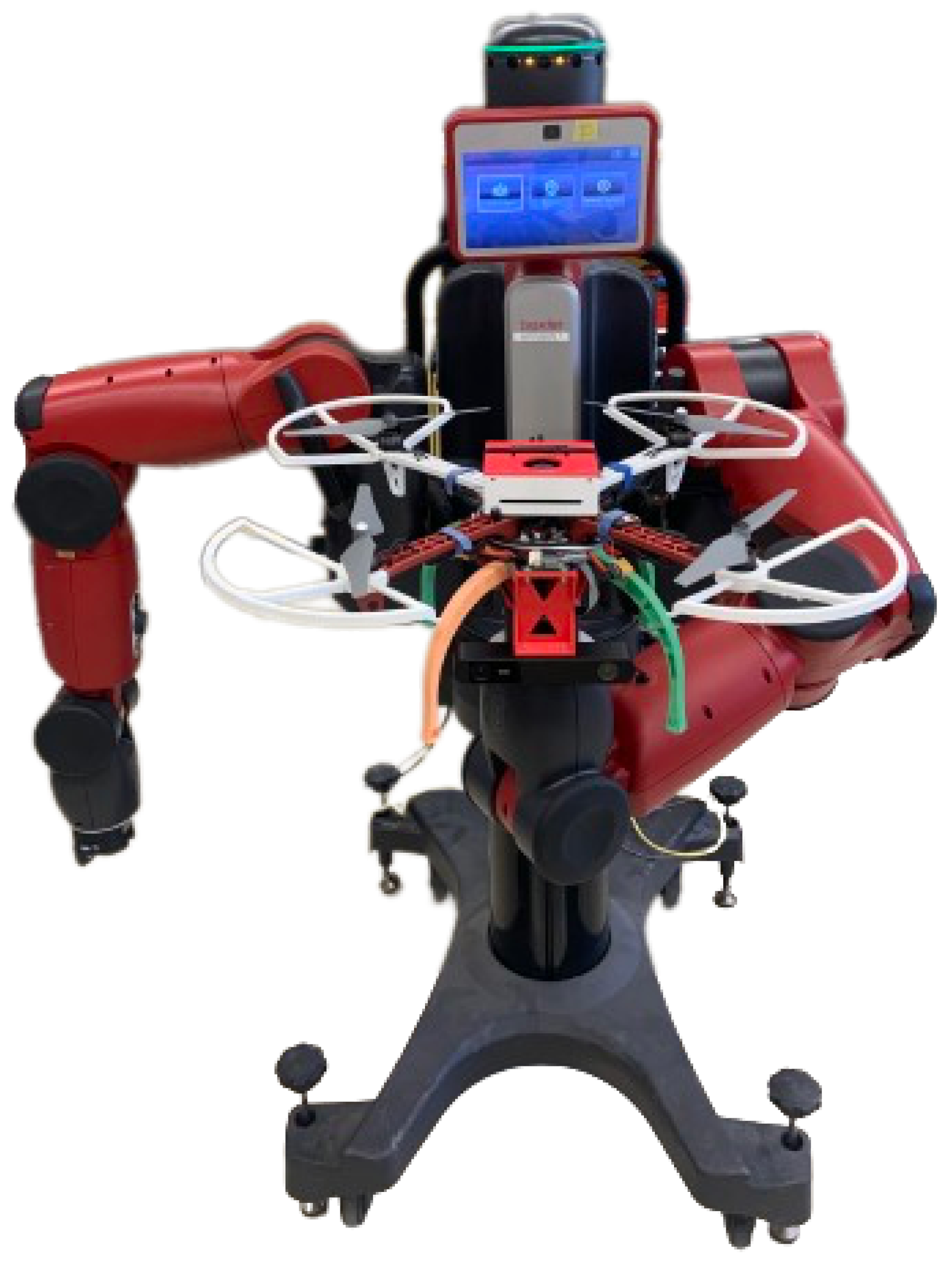
The maximal forces and torques generated by the drone were measured in an experiment using the end-effector force and torque-sensing capabilities of the Rethink Robotics (Boston, MA, USA) Baxter robot installed in our lab. The experimental setup is presented in Figure 7.
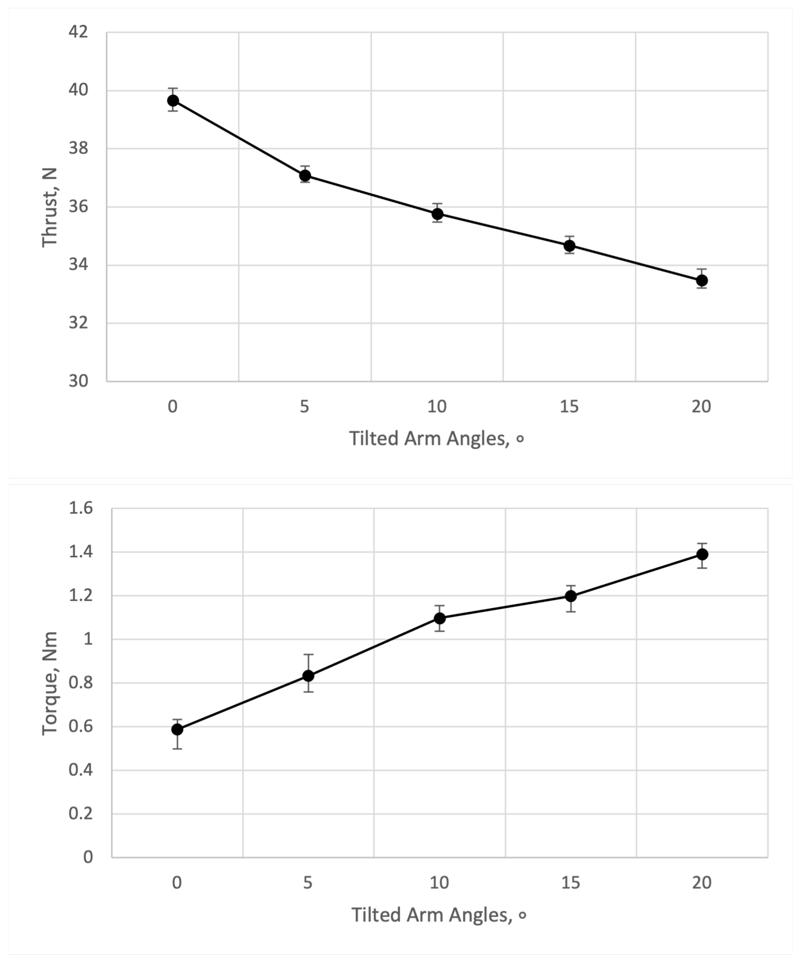
The quadcopter was rigidly attached to a platform held by the end-effector of the robot. In a series of two independent experiments, the drone was commanded with full (100%) control inputs along the thrust and then the yaw axis, with each experiment repeated over three trials to obtain an average. The Baxter robot was commanded to maintain the end-effector in a fixed orientation during the test, and the resulting steady-state end-effector wrench (force and torque) was logged and averaged out over three separate runs for each arm twist angle. The results are plotted in Figure 8.
Figure 8 shows that, as the twist angle is increased, the maximum possible thrust is reduced, while the maximum possible torque increases. The percentage changes in both these quantities as a function of twist angle change are shown in Figure 9.
Based on the experimental data, we selected a 10° twist angle for the final version of the drone prototype, which reduced the maximal thrust by 10.7% but increased the maximal torque by 53.7% from the stock (zero twist) rotor arms. Using flight experiments, it was found that, under this configuration, the drone was able to maintain near-constant altitude even under very aggressive yawing (turning) maneuvers, meaning the original issue had been resolved. Videos of the experimental flight performance before and after this modification are available as Supplementary Files for this article, which clearly illustrate both the severity of this issue in the stock (zero arm twist) configuration, as well as its resolution in the modified (twisted arm) version. Note that the parameters of the onboard Pixhawk 5X flight controller were not changed between the two flights since the modification does not alter the handling characteristics of the vehicle at or close to steady hover.

4. Results

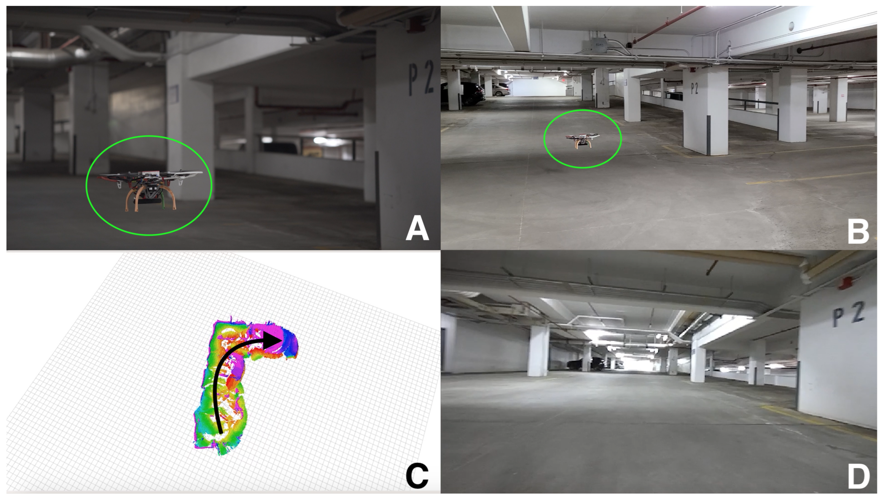
In order to test our drone system in real-world conditions, the quadcopter was flown in the second level of an underground car parkade, whose depth guaranteed an absence of GNSS signals. A composite of the experimental flight test is shown in Figure 10, while the full video of the flight is available as a Supplementary File for this article. We state upfront that the hardware testing will be limited to a single long-duration flight, with only a qualitative ground truth available from a manually created 2D map of the environment. Our goal is to experimentally demonstrate that our low-cost drone is able to perform autonomous flight in real-world conditions with challenges such as constrained flight spaces. Further testing involving simulated search-and-rescue scenarios and qualitative ground truth for assessing the performance levels of our design are left for future work.
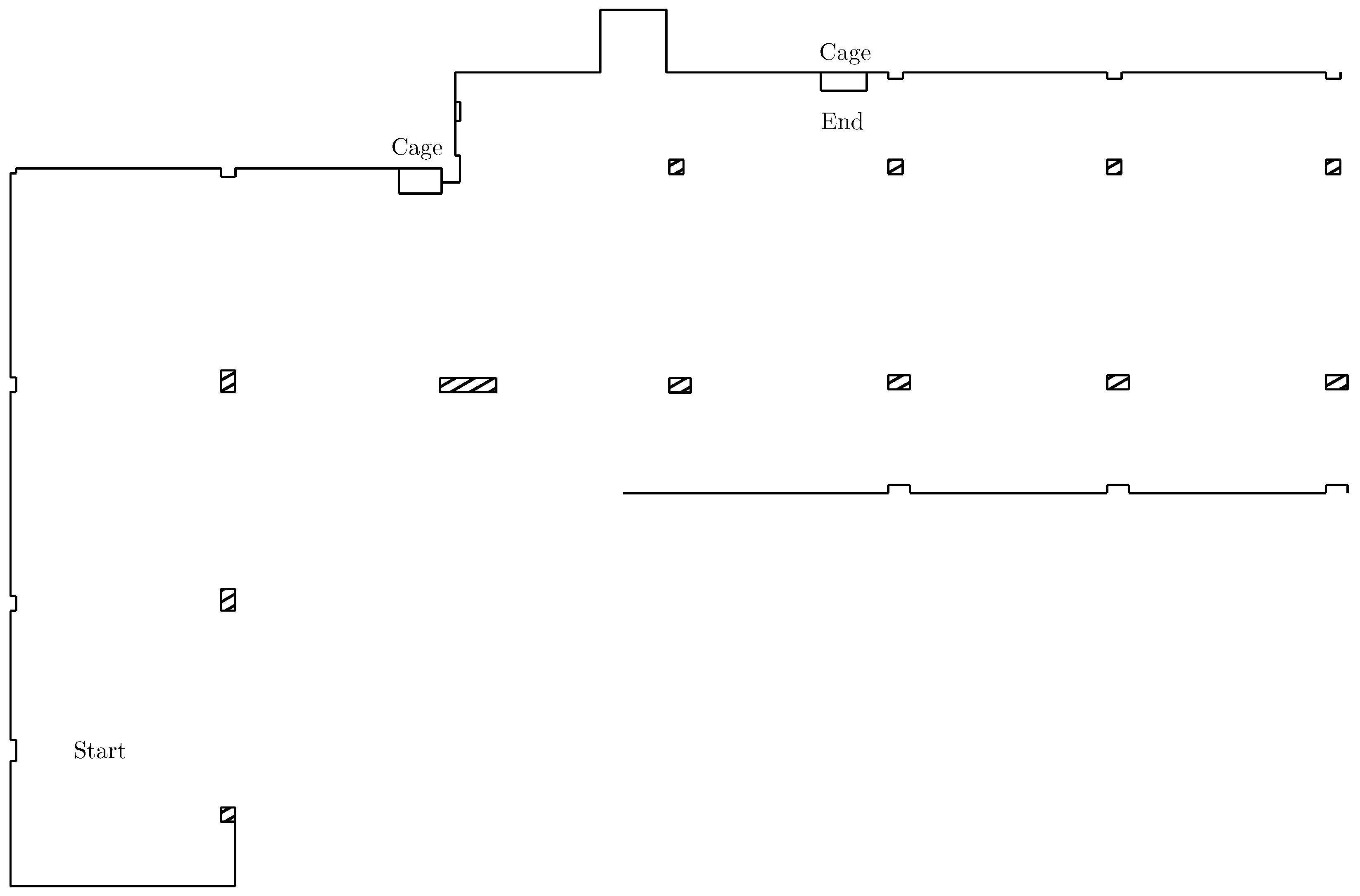
As seen in the pictures in Figure 10 and the aforementioned flight video, the underground parkade has outer walls forming a rectangular structure, a collection of rectangular- and square-shaped support pillars, and rectangular chain-link fence structures to protect infrastructure near walls, including pipes and electrical panels. An overhead diagram of the parkade section where the flight experiment was performed is shown in Figure 11, drawn to scale from manual distance measurements of the parkade using a hand-held laser rangefinder. The right angles of the flight area provide a visual reference for the maps generated by the system, while the pillars provide restricted flying corridors to validate the drone’s onboard autonomous navigation capabilities.
Due to the large size of the underground parkade, we could not install an off-board motion capture system to capture the ground truth of the drone’s trajectory, and, due to the small payload capacity of the present design, we also could not add the aforementioned Velodyne Puck LITE (0.59 kg mass) from our previous work in order to obtain reference data. As a result, we will be unable to precisely quantify the positioning accuracy of our system.
During flight testing, the limits on the drone’s velocity and acceleration magnitudes were set to 0.3 m/s and 0.5 m/s2, respectively. These limits were chosen to offset the bottleneck created by depth image processing, which ran at 8 frames per second due to the computational power of the onboard Jetson Xavier NX single-board computer; if this bottleneck were removed, the depth images could be generated at a higher rate, consequently increasing the speed limits of the system. We investigated reducing the quality of the depth images to increase their rate, but this was found not to work since the quality of the data degraded to unacceptable levels, particularly in areas with low-contrast low-texture surfaces such as the walls of the car parkade. A more thorough study of the quality and rate of the depth images versus the performance of the system would also require positioning information and thus was not performed.
Figure 12 illustrates the functioning of FUEL at the start of the experiment. The left image in Figure 12 shows the initial generated frontiers. Since there is little information available about the surroundings, large frontiers are visible. The frontiers are automatically subdivided (seen as blue, red, and purple regions) to improve decision-making by the exploration algorithm. The right image in Figure 12 depicts a reference local trajectory guiding the drone towards an unexplored area. Note that the path avoids the obstruction detected in the initial view to guide the vehicle to an unexplored area of the map.
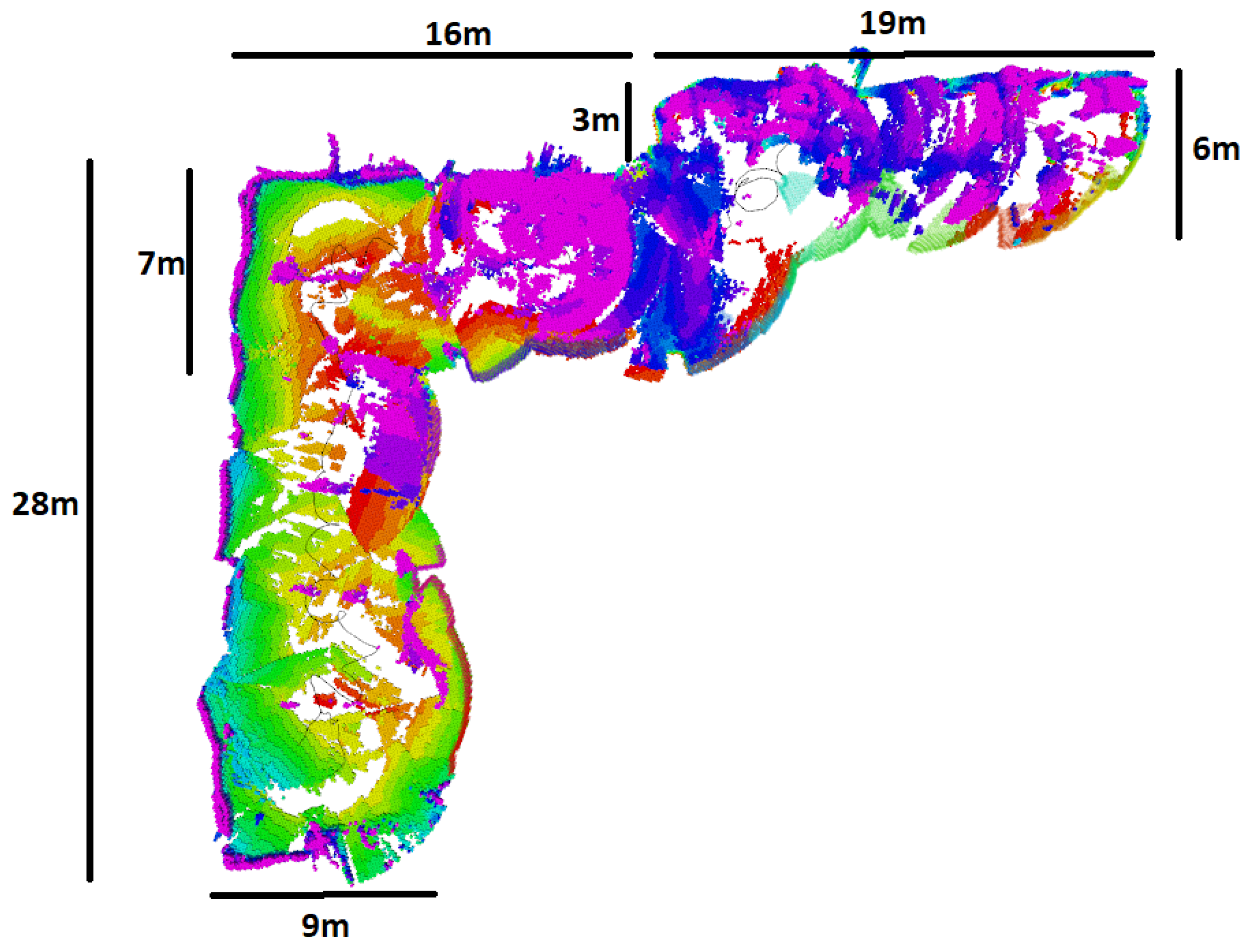
The total flight time of the drone was 3 min and 39 s. During this flight, the vehicle autonomously navigated through a previously unmapped environment consisting of open regions, tight corners, and narrow passages, with a floor-to-ceiling height of 3 m. An overhead view of the generated volumetric map with a volume of 518 m3 is shown in Figure 13. The total length of the vehicle’s flight path is 93 m. Notably, the generated map visually agrees with the parkade schematic presented earlier in Figure 11 (for instance, the 90° corners on the left-hand wall and the leftward opening along the top wall past the first cage). This visual match indicates that the pose estimates from our system are accurate over the course of the performed experiment.
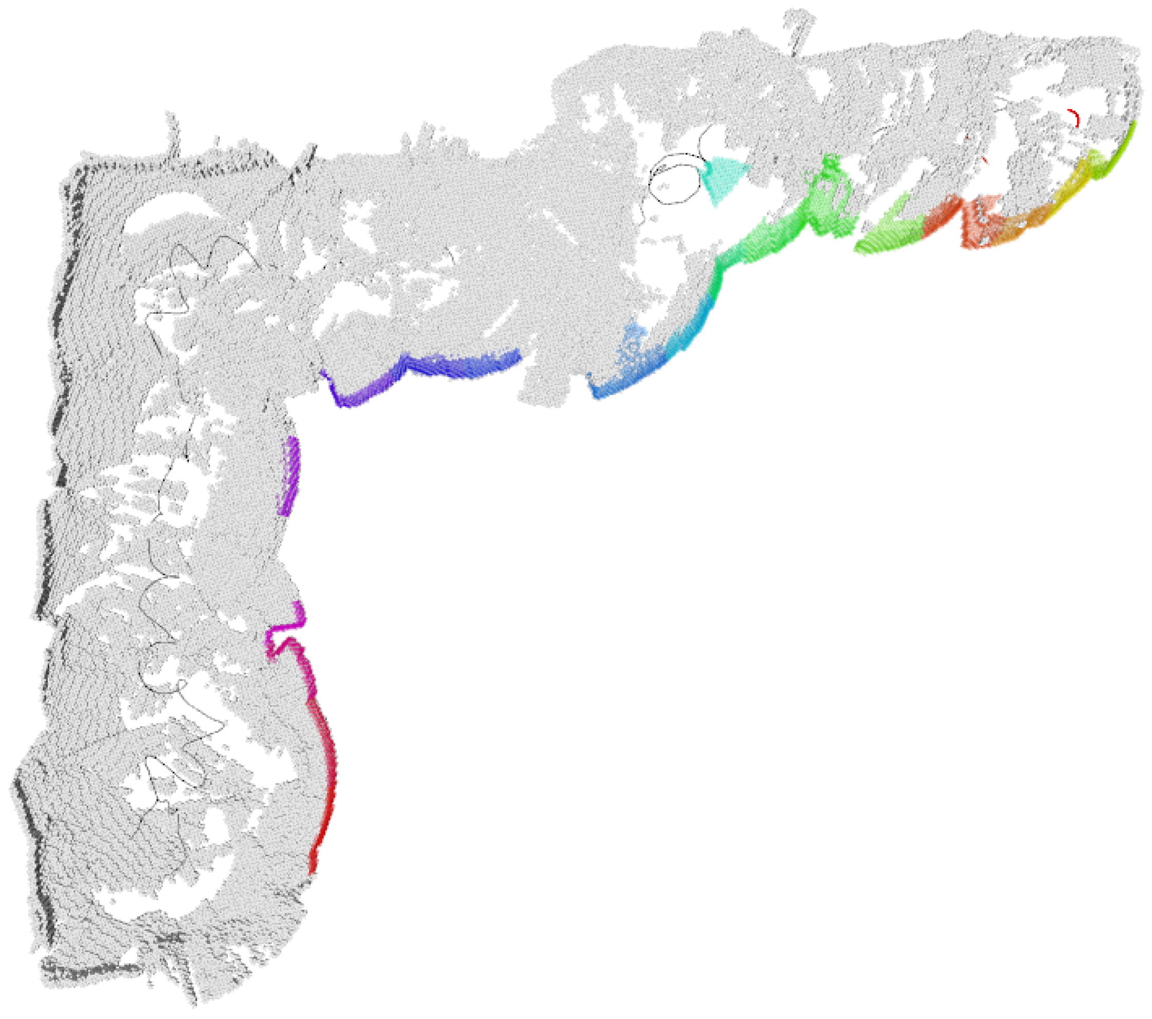
The drone’s flight time and speed limits allowed it to explore a subset of the full underground parkade. This is seen in Figure 14, which shows the still-unexplored frontiers as colored boundaries.

5. Conclusions

Fully autonomous drone flight in GNSS-denied environments is a complex task involving challenges with both hardware and software. Our system successfully demonstrated this capability in a single proof-of-concept flight experiment, which demonstrated the ability of the drone to autonomously navigate through an unknown environment with confined areas. Quantifying the performance of our system would require both an accurate source of ground truth and a much larger number of flight trials to ensure statistical significance and thus is left for future studies.
The considerations included the airframe design, choice of sensors, and software for autonomous flight planning. Our proposed design was an evolution of our earlier work involving a much heavier and more expensive hexacopter system relying on a 360° Velodyne LiDAR sensor for environmental sensing. Our design was built upon lessons learned from our previous drone platform to reduce costs while still completing the same mission profile. The present design makes use of the FUEL algorithm to perform autonomous navigation relying solely on a stereo camera. The proposed design and methodologies were successfully validated through experimental flight testing, including a full-scale exploration experiment in a GNSS-denied underground car parkade. Our research provides a benchmark for future research in the field of low-cost autonomous flight exploration of unknown environments.
There remain a number of challenges related to autonomous drone operations in GNSS-denied environments. One is the limitation in computing power available on a single-board computer. This restriction was shown in our need to reduce the output rate of the depth images, which resulted in imposing limits on the maximum velocity of the drone. This challenge can be addressed through a combination of using different depth image sensors with their own onboard processing, deploying more efficient algorithms, and/or upgrading to a more powerful onboard computing platform.
The existing airframe design includes safety elements such as propeller guards but still requires careful handling by human operators as well as conservative flying near obstacles such as walls. A solution is to change the airframe design to a configuration such as a coaxial ducted fan, which keeps the propellers enclosed, or a “cage” structure around the vehicle. Conversely, these alternative designs will add more weight and require retuning the flight control laws to achieve performance similar to our current iteration.
Finally, the state of charge of the battery should be actively measured and integrated into the FUEL algorithm. This solution would adjust the exploration trajectory to maximize coverage while maintaining sufficient energy to return to the starting location to swap or recharge the battery. Energy use should also be modeled in the low-level motion primitives, encouraging smoother trajectories and optimal speeds to minimize power draw and thus maximize the flight time of the vehicle.
By implementing the above ideas, we anticipate that we can further improve the performance of our existing drone and make it even more useful for assisting first responders performing search-and-rescue missions in GNSS-denied environments, such as underground mines, indoor spaces, or densely built-up urban areas.

Supplementary Materials

The following supporting information can be downloaded at https://www.mdpi.com/article/10.3390/drones9080523/s1: flight videos of drone with stock (zero arm twist) and modified (10° arm twist) configurations, c.f. Section 3.4; video of full experimental flight, c.f. Section 4.

Author Contributions

Conceptualization, S.A. and M.B.; methodology, S.A.; software, S.A.; validation, S.A.; formal analysis, S.A.; investigation, S.A.; resources, M.B.; data curation, S.A.; writing—original draft preparation, S.A.; writing—review and editing, M.B.; visualization, S.A.; supervision, M.B.; project administration, M.B.; funding acquisition, M.B. All authors have read and agreed to the published version of the manuscript.

Funding

This research was funded by NSERC Alliance-Alberta Innovates Advance Program grant number ALLRP 560994-20.

Data Availability Statement

The raw data supporting the conclusions of this article will be made available by the authors on request.

Conflicts of Interest

The authors declare no conflicts of interest. The funders had no role in the design of the study; in the collection, analyses, or interpretation of data; in the writing of the manuscript; or in the decision to publish the results.

References

  1. Marconi, L.; Melchiorri, C.; Beetz, M.; Pangercic, D.; Siegwart, R.; Leutenegger, S.; Carloni, R.; Stramigioli, S.; Bruyninckx, H.; Doherty, P.; et al. The SHERPA project: Smart collaboration between humans and ground-aerial robots for improving rescuing activities in alpine environments. In Proceedings of the 2012 IEEE International Symposium on Safety, Security, and Rescue Robotics, College Station, TX, USA, 5–8 November 2012; pp. 1–4. [Google Scholar]
  2. De Cubber, G.; Doroftei, D.; Serrano, D.; Chintamani, K.; Sabino, R.; Ourevitch, S. The EU-ICARUS project: Developing assistive robotic tools for search and rescue operations. In Proceedings of the 2013 IEEE International Symposium on Safety, Security, and Rescue Robotics, Linköping, Sweden, 21–26 October 2013; pp. 1–4. [Google Scholar]
  3. Półka, M.; Ptak, S.; Kuziora, Ł. The use of UAV’s for search and rescue operations. Procedia Eng. 2017, 192, 748–752. [Google Scholar] [CrossRef]
  4. Huang, H.M. Autonomy Levels for Unmanned Systems (ALFUS) Framework Volume I: Terminology Version 2.0; Special Publication 1011; National Institute of Standards and Technology: Gaithersburg, MD, USA, 2004. [CrossRef]
  5. Balestrieri, E.; Daponte, P.; De Vito, L.; Lamonaca, F. Sensors and Measurements for Unmanned Systems: An Overview. Sensors 2021, 21, 1518. [Google Scholar] [CrossRef] [PubMed]
  6. Zhang, M.; Li, K.; Hu, B.; Meng, C. Comparison of Kalman Filters for Inertial Integrated Navigation. Sensors 2019, 19, 1426. [Google Scholar] [CrossRef] [PubMed]
  7. Lu, Y.; Xue, Z.; Xia, G.S.; Zhang, L. A survey on vision-based UAV navigation. Geo-Spacial Inf. Sci. 2018, 21, 21–32. [Google Scholar] [CrossRef]
  8. Ko, H.; Kim, B.; Kong, S.H. GNSS multipath-resistant cooperative navigation in urban vehicular networks. IEEE Trans. Veh. Technol. 2015, 64, 5450–5463. [Google Scholar] [CrossRef]
  9. Martz, J.; Al-Sabban, W.; Smith, R.N. Survey of unmanned subterranean exploration, navigation, and localisation. IET Cyber-Syst. Robot. 2020, 2, 1–13. [Google Scholar] [CrossRef]
  10. Forrest, S.W.; Recio, M.R.; Seddon, P.J. Moving wildlife tracking forward under forested conditions with the SWIFT GPS algorithm. Anim. Biotelemetry 2022, 10, 19. [Google Scholar] [CrossRef]
  11. Schmidt, G.T. Navigation sensors and systems in GNSS degraded and denied environments. Chin. J. Aeronaut. 2015, 28, 1–10. [Google Scholar] [CrossRef]
  12. Placed, J.A.; Strader, J.; Carrillo, H.; Atanasov, N.; Indelman, V.; Carlone, L.; Castellanos, J.A. A survey on active simultaneous localization and mapping: State of the art and new frontiers. IEEE Trans. Robot. 2023, 39, 1686–1705. [Google Scholar] [CrossRef]
  13. Jarraya, I.; Al-Batati, A.; Kadri, M.B.; Abdelkader, M.; Ammar, A.; Boulila, W.; Koubaa, A. Gnss-denied unmanned aerial vehicle navigation: Analyzing computational complexity, sensor fusion, and localization methodologies. Satell. Navig. 2025, 6, 9. [Google Scholar] [CrossRef]
  14. Orekhov, V.L.; Chung, T.H. The DARPA subterranean challenge: A synopsis of the circuits stage. Field Robot. 2022, 2, 735–747. [Google Scholar] [CrossRef]
  15. Tranzatto, M.; Miki, T.; Dharmadhikari, M.; Bernreiter, L.; Kulkarni, M.; Mascarich, F.; Andersson, O.; Khattak, S.; Hutter, M.; Siegwart, R.; et al. CERBERUS: Autonomous Legged and Aerial Robotic Exploration in the Tunnel and Urban Circuits of the DARPA Subterranean Challenge. Field Robot. 2022, 2, 274–324. [Google Scholar] [CrossRef]
  16. Hudson, N.; Talbot, F.; Cox, M.; Williams, J.; Hines, T.; Pitt, A.; Wood, B.; Frousheger, D.; Surdo, K.L.; Molnar, T.; et al. Heterogeneous Ground and Air Platforms, Homogeneous Sensing: Team CSIRO Data61’s Approach to the DARPA Subterranean Challenge. Field Robot. 2022, 2, 595–636. [Google Scholar] [CrossRef]
  17. Jones, E.; Sofonia, J.; Canales, C.; Hrabar, S.; Kendoul, F. Applications for the Hovermap autonomous drone system in underground mining operations. J. S. Afr. Inst. Min. Metall. 2020, 120, 49–56. [Google Scholar] [CrossRef]
  18. Al Younes, Y.; Barczyk, M. Adaptive Nonlinear Model Predictive Horizon Using Deep Reinforcement Learning for Optimal Trajectory Planning. Drones 2022, 6, 323. [Google Scholar] [CrossRef]
  19. Al Younes, Y.; Barczyk, M. Optimal Motion Planning in GPS-Denied Environments Using Nonlinear Model Predictive Horizon. Sensors 2021, 21, 5547. [Google Scholar] [CrossRef] [PubMed]
  20. Al Younes, Y.; Barczyk, M. Nonlinear model predictive horizon for optimal trajectory generation. Robotics 2021, 10, 90. [Google Scholar] [CrossRef]
  21. Al Younes, Y.; Barczyk, M. A backstepping approach to nonlinear model predictive horizon for optimal trajectory planning. Robotics 2022, 11, 87. [Google Scholar] [CrossRef]
  22. Dang, T.; Mascarich, F.; Khattak, S.; Papachristos, C.; Alexis, K. Graph-based Path Planning for Autonomous Robotic Exploration in Subterranean Environments. In Proceedings of the IEEE International Conference on Intelligent Robots and Systems, Macau, China, 3–8 November 2019; pp. 3105–3112. [Google Scholar] [CrossRef]
  23. Zhou, B.; Zhang, Y.; Chen, X.; Shen, S. FUEL: Fast UAV exploration using incremental frontier structure and hierarchical planning. IEEE Robot. Autom. Lett. 2021, 6, 779–786. [Google Scholar] [CrossRef]
  24. Zhou, B.; Gao, F.; Wang, L.; Liu, C.; Shen, S. Robust and Efficient Quadrotor Trajectory Generation for Fast Autonomous Flight. IEEE Robot. Autom. Lett. 2019, 4, 3529–3536. [Google Scholar] [CrossRef]
  25. Tian, Y.; Liu, K.; Ok, K.; Tran, L.; Allen, D.; Roy, N.; How, J.P. Search and rescue under the forest canopy using multiple UAVs. Int. J. Robot. Res. 2020, 39, 1201–1221. [Google Scholar] [CrossRef]
  26. Schleich, D.; Beul, M.; Quenzel, J.; Behnke, S. Autonomous Flight in Unknown GNSS-denied Environments for Disaster Examination. In Proceedings of the 2021 International Conference on Unmanned Aircraft Systems, Athens, Greece, 15–18 June 2021; pp. 950–957. [Google Scholar] [CrossRef]
  27. Lindqvist, B.; Kanellakis, C.; Mansouri, S.S.; Agha-mohammadi, A.a.; Nikolakopoulos, G. COMPRA: A COMPact reactive autonomy framework for subterranean MAV based search-and-rescue operations. J. Intell. Robot. Syst. 2022, 105, 49. [Google Scholar] [CrossRef]
  28. Shan, T.; Englot, B.; Meyers, D.; Wang, W.; Ratti, C.; Daniela, R. LIO-SAM: Tightly-coupled Lidar Inertial Odometry via Smoothing and Mapping. In Proceedings of the IEEE/RSJ International Conference on Intelligent Robots and Systems, Las Vegas, NV, USA, 25–29 October 2020; pp. 5135–5142. [Google Scholar] [CrossRef]
  29. Dharmadhikari, M.; Dang, T.; Solanka, L.; Loje, J.; Nguyen, H.; Khedekar, N.; Alexis, K. Motion Primitives-based Path Planning for Fast and Agile Exploration using Aerial Robots. In Proceedings of the 2020 IEEE International Conference on Robotics and Automation, Paris, France, 31 May–31 August 2020; pp. 179–185. [Google Scholar] [CrossRef]
  30. Chan, T.H.; Halim, J.K.D.; Tan, K.W.; Tang, E.; Ang, W.J.; Tan, J.Y.; Cheong, S.; Ho, H.-N.; Kuan, B.; Shalihan, M.; et al. A Robotic System of Systems for Human-Robot Collaboration in Search and Rescue Operations. In Proceedings of the 2023 IEEE/ASME International Conference on Advanced Intelligent Mechatronics, Seattle, WA, USA, 28–30 June 2023; pp. 878–885. [Google Scholar] [CrossRef]
  31. Ngo, E.; Ramirez, J.; Medina-Soto, M.; Dirksen, S.; Victoriano, E.D.; Bhandari, S. UAV Platforms for Autonomous Navigation in GPS-Denied Environments for Search and Rescue Missions. In Proceedings of the 2022 International Conference on Unmanned Aircraft Systems, Dubrovnik, Croatia, 21–24 June 2022; pp. 1481–1488. [Google Scholar] [CrossRef]
  32. Labbé, M.; Michaud, F. RTAB-Map as an open-source lidar and visual simultaneous localization and mapping library for large-scale and long-term online operation. J. Field Robot. 2019, 36, 416–446. [Google Scholar] [CrossRef]
  33. Redmon, J.; Farhadi, A. YOLOv3: An incremental improvement. arXiv 2018. arXiv:1804.02767. [Google Scholar] [CrossRef]
  34. Elmokadem, T.; Savkin, A.V. Towards Fully Autonomous UAVs: A Survey. Sensors 2021, 21, 6223. [Google Scholar] [CrossRef] [PubMed]
  35. Tahir, A.; Boling, J.; Haghbayan, M.H.; Toivonen, H.T.; Plosila, J. Swarms of Unmanned Aerial Vehicles—A Survey. J. Ind. Inf. Integr. 2019, 16, 100106. [Google Scholar] [CrossRef]
  36. Giordan, D.; Adams, M.S.; Aicardi, I.; Alicandro, M.; Allasia, P.; Baldo, M.; Berardinis, P.D.; Dominici, D.; Godone, D.; Hobbs, P.; et al. The use of unmanned aerial vehicles (UAVs) for engineering geology applications. Bull. Eng. Geol. Environ. 2020, 79, 3437–3481. [Google Scholar] [CrossRef]
  37. Yamauchi, B. A frontier-based approach for autonomous exploration. In Proceedings of the 1997 IEEE International Symposium on Computational Intelligence in Robotics and Automation, Monterey, CA, USA, 10–11 July 1997; pp. 146–151. [Google Scholar] [CrossRef]
  38. Fischetti, M.; Lodi, A.; Toth, P. Exact Methods for the Asymmetric Traveling Salesman Problem. In The Traveling Salesman Problem and Its Variations; Springer: Boston, MA, USA, 2007; pp. 169–205. [Google Scholar] [CrossRef]
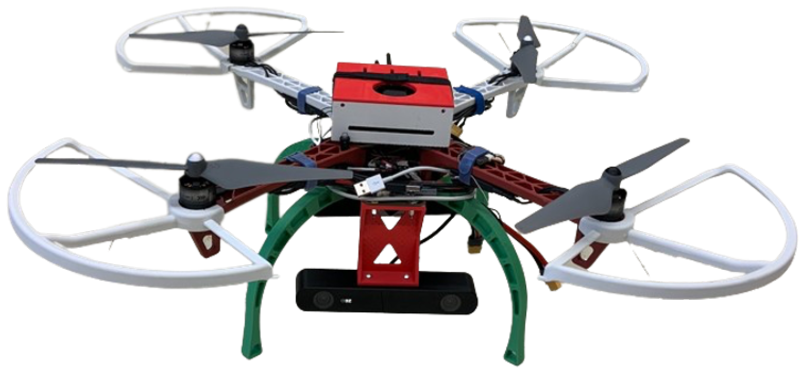
Figure 1. Picture of our quadcopter prototype.
Drones 09 00523 g001
Figure 2. Quadcopter airframe with sign conventions.
Drones 09 00523 g002
Figure 3. Quadcopter upwards drift during forward flight in hardware testing.
Drones 09 00523 g003
Figure 4. Software architecture and information transmission.
Drones 09 00523 g004
Figure 5. Quadcopter global motion planner architecture.
Drones 09 00523 g005
Figure 6. Three-dimensionally printed mounts with 5°, 10°, 15°, and 20° twist angles.
Drones 09 00523 g006
Figure 7. Test rig used for experimental thrust and torque measurements.
Drones 09 00523 g007
Figure 8. Maximum thrust and torque as a function of the arm twist angle.
Drones 09 00523 g008
Figure 9. Force and torque percent change as a result of the quadcopter arm tilt angle.
Drones 09 00523 g009
Figure 10. (A) Quadcopter drone in flight (drone manually highlighted). (B) Underground parkade (drone manually highlighted). (C) Voxel grid mapping (arrow annotation shows flight trajectory). (D) Image from drone’s onboard camera.
Drones 09 00523 g010
Figure 11. Overhead diagram of parkade section used for flight test; support pillars, fenced-off cage areas, and drone’s take-off (Start) and landing (End) positions are marked.
Drones 09 00523 g011
Figure 12. Frontier clusters with colored regions indicating automatically subdivided frontiers (a) and local trajectory generation (b).
Drones 09 00523 g012
Figure 13. Overhead view of map generated during flight experiment with colored regions indicating different frontiers.
Drones 09 00523 g013
Figure 14. Unexplored identified frontiers during experimental flight test with colored regions indicating different unexplored frontiers.
Drones 09 00523 g014
Table 1. Hardware components of quadcopter.
ComponentBrand
AirframeDJI (Shenzhen, China) FlameWheel 450
Altitude SensorGarmin (Olathe, KS, USA) LiDAR-LITE v3
Flight ControllerHolybro (Shenzhen, China) Pixhawk 5x
Onboard ComputerNVIDIA (Santa Clara, CA, USA) Jetson Xavier NX
Depth SensorStereolabs (Paris, France) ZED 2 Camera
Electronic Speed ControllersDJI (Shenzhen, China) 430 Lite
Propeller MotorsDJI (Shenzhen, China) 2312E
Computer StorageSamsung (Seoul, Korea) 970 EVO Plus SSD
WiFi ModuleWaveshare (Shenzhen, China) AW-CB375NF
PropellersDJI (Shenzhen, China) Z-Blade 9450
Primary BatteryVenom (Rathdrum, ID, USA) 14.8 V 5000 mAh 50C LiPo
Secondary BatteryVenom (Rathdrum, ID, USA) 11.1 V 2200 mAh 50C LiPo
Disclaimer/Publisher’s Note: The statements, opinions and data contained in all publications are solely those of the individual author(s) and contributor(s) and not of MDPI and/or the editor(s). MDPI and/or the editor(s) disclaim responsibility for any injury to people or property resulting from any ideas, methods, instructions or products referred to in the content.