1. Introduction
Society is being transformed by numerous technological innovations propelled by the rapid growth of the Internet of Things (IoT), including industrial automation, smart homes, and smart cities. The construction of smart cities heavily relies on large-scale, multi-source, and real-time data collection and analysis. As the core driver of smart cities, data directly impact the intelligence level of urban management, resource utilization efficiency, and user experience quality. By deploying large-scale IoT terminals such as sensors and cameras, cities can collect real-time data on traffic flow, air quality, energy consumption, and public safety. After analysis, these data help urban administrators optimize traffic signal timing, adjust public transport routes, and predict environmental pollution trends, thereby achieving more efficient resource allocation and precision governance. However, to extend the operational lifetime of these sensor nodes (SNs), their power supply is often constrained, which significantly limits data upload capacity. To meet the data demands of smart cities under resource-constrained conditions, unmanned aerial vehicles (UAVs) present an efficient solution due to their mobility and rapid deployment capabilities. Specifically, UAVs can assist data collection by either acting as relays to forward data to base stations (BSs) or directly serving as aerial BSs, collaborating with ground-based IoT systems to establish an “air–ground-integrated” monitoring network.
Although UAVs demonstrate significant potential in data collection, their practical deployment still faces several challenges. The most critical issue is the dynamic and uncertain communication environment, where signal transmission reliability cannot be guaranteed, potentially compromising data collection efficiency. Fortunately, the development of IoT has been accompanied by significant progress in wireless communication technologies, including Massive MIMO, ultra-dense networks (UDNs), and non-orthogonal multiple access (NOMA). Among these, NOMA enables the simultaneous servicing of multiple users within the same time, frequency, or code domain, thereby substantially enhancing spectral efficiency (SE) to support the large-scale connectivity needs of IoT. In particular, power-domain NOMA (PD-NOMA) boosts SE by allowing users with varying channel conditions and transmission power levels to share the same resource blocks. Due to this power disparity, the receiver can successfully decode signals using successive interference cancellation (SIC). To address the challenges of excessive energy consumption and hardware costs, RIS and their variants show great promise in beyond-5G (B5G) wireless networks. An RIS is typically a two-dimensional structure composed of numerous controllable electromagnetic elements. These elements can dynamically adjust the reflection characteristics of electromagnetic waves, including phase and amplitude, thereby altering the propagation path and properties of wireless signals to create a smart radio environment (SRE). Unlike conventional multi-antenna and relay technologies, RIS requires no radio frequency (RF) chains, making it more cost-effective and environmentally friendly. This nature significantly reduces both energy expenditure and hardware complexity while maintaining superior performance in signal manipulation.
Despite its advantages, RIS suffers from certain inherent limitations, especially in terms of coverage. As RIS operates solely by reflecting incident signals, it becomes ineffective when the transmitter and receiver are positioned on opposite sides of the surface. To this end, the concept of STAR-RIS has been introduced. STAR-RIS integrates both reflection and transmission functions on a single surface, enabling bidirectional signal manipulation. Each element can dynamically switch between reflection and transmission modes as needed, allowing flexible management of signal propagation paths. The introduction of STAR-RIS has greatly broadened its range of potential applications. By enabling the dynamic adjustment of transmission and reflection coefficients, it offers enhanced flexibility in improving wireless network efficiency within the SRE framework. To address multiplicative path loss caused by cascaded channels, active STAR-RIS incorporates embedded power amplifiers to provide power compensation for reflected/transmitted signals. This active implementation simultaneously improves signal strength and transmission coverage, enabling service to distant ground devices and offering an effective solution for complex environments.
Moreover, airborne STAR-RIS faces several challenges. First, active STAR-RIS requires an external power supply, which imposes a significant burden on UAV systems with limited energy capacity. The integration of STAR-RIS on UAVs increases the payload of the aerial platform, potentially affecting its flight endurance and stability. To address this, we employ an accurate energy consumption model to estimate the energy required for each mission, ensuring the UAV can complete its task. In addition, maintaining precise beamforming performance becomes technically challenging in scenarios involving high-speed UAV movement and rapidly varying channels. We mitigate this issue by leveraging pre-designed beamforming patterns and the dynamic geometric relationships among the SN-USR(UAVs equipped with active STAR-RIS)-BS links.
Based on the detailed analysis of active STAR-RIS and UAV advantages provided earlier, we propose an active STAR-RIS-assisted UAV-enabled NOMA data collection system that jointly optimizes active STAR-RIS beamforming, SN power allocation, and UAV trajectory to maximize the system EE and the DCCR. The primary contributions of this work are outlined below:
We propose an active STAR-RIS-assisted UAV NOMA network for data collection, where the UAV with STAR-RIS relays ground sensor data to a BS via NOMA for spectrum sharing. Prioritizing data integrity in smart cities, we impose a constraint on complete data collection rate and formulate an optimization problem to maximize system energy efficiency by jointly optimizing active STAR-RIS beamforming, UAV trajectory, and SN power allocation.
To effectively solve the non-convex problem with variable coupling, we adopt an alternating optimization (AO) strategy to progressively obtain the optimal solution. Using the BCA method, the problem is split into three subproblems: active STAR-RIS beamforming, SN power allocation, and UAV trajectory design.
Finally, simulation results demonstrate the fast convergence of the proposed scheme and validate its effectiveness in improving both the DCCR and system EE.
The remainder of this paper is structured as follows: The related work is described in
Section 2.
Section 3 outlines our system model and presents the problem formulation.
Section 4 introduces our algorithms. The simulation setup and the validation of the proposed algorithm are presented in
Section 5, and
Section 6 concludes the paper.
2. Related Work
2.1. RIS-Assisted UAV Networks
In RIS-assisted UAV networks, RIS can be categorized into ground-based RIS and aerial RIS based on deployment, and active RIS and passive RIS (reflection-only) based on functionality. Wang et al. [
1] proposed an Age of Information (AoI)-based secure transmission strategy for UAV-RIS systems, which employs PSO/GA heuristic algorithms to schedule sensors for phased optimization of data collection, transforms the problem into secrecy rate maximization, and optimizes RIS reflection coefficients for data uploading, effectively reducing the AoI of private information. Diao et al. [
2] investigated the reflective element optimization in NOMA-assisted UAV-RIS systems by deriving closed-form expressions for air-to-ground (A2G) channels considering phase errors to maximize energy secrecy efficiency (ESE). The results demonstrate that RIS significantly enhances anti-eavesdropping capabilities, with the NOMA-UAV scheme outperforming traditional terrestrial systems, providing theoretical foundations for RIS deployment in heterogeneous service scenarios. Shen et al. [
3] developed a UAV-RIS-assisted wireless powered communication network (WPCN) framework for urban environments, employing Time division multiple access (TDMA) to coordinate simultaneous wireless information and power transfer (SWIPT) while jointly optimizing UAV trajectory, node scheduling, and the RIS phase shift matrix. The DRL-based solution shows that dynamic TDMA improves node throughput while conventional TDMA enhances energy harvesting efficiency, establishing a key optimization paradigm for urban UAV communication network design.
Studies [
4,
5] focus on aerial RIS applications. Liu et al. [
4] proposed a 3D jitter-aware RIS-assisted communication scheme, establishing an elevation-angle-dependent dynamic A2G channel model to address non-ideal reflection caused by UAV platform vibrations. Zhao et al. [
6] developed an active RIS (ARIS)-assisted multi-UAV NOMA network featuring dual-mode switching (passive reflection/active transmission) for enhanced channel controllability. The authors in [
5] introduced a UAV-RIS-enabled massive IoT data collection system that improves network performance through coverage probability optimization and a novel MAC protocol design. For metaverse-oriented communications, ref. [
7] proposed an innovative irregular RIS-assisted multi-UAV cross-layer architecture, reducing connection overhead through optimized RIS topology and employing Bernstein’s inequality to handle outage constraints under imperfect CSI. Simulations demonstrate simultaneous QoS guarantee, 40% system energy efficiency improvement, and enhanced user connectivity experience. Li et al. proposed a cognitive radio-enabled active RIS-NOMA space–air–ground network architecture [
8], where UAVs flexibly serve secondary network users, and satellites provide backhaul support. This study employs an alternating optimization method to jointly optimize power allocation, RIS configuration, user matching, and UAV trajectory, significantly improving the weighted rate and energy efficiency performance of the secondary network.
2.2. STAR-RIS-Assisted UAV Networks
Studies in [
9,
10] explored the significant impact of STAR-RIS on improving wireless communication systems. In particular, Sui et al. [
9] proposed one of the earliest STAR-RIS-assisted cell-free mMIMO architectures, establishing an MMSE channel estimation framework with hardware impairment considerations and deriving closed-form spectral efficiency (SE) analysis. They developed an AO-APSO-based joint beamforming and power control algorithm that optimizes worst-user fairness. In [
10], the authors proposed an innovative STAR-RIS-assisted uplink RSMA scheme, featuring an alternating optimization-based algorithm that reduces computational complexity by 42% compared to conventional methods. The solution demonstrates 35% higher total throughput, and the user fairness index has increased by 2.1 times over NOMA/OMA alternatives.
The studies in [
11,
12] explore STAR-RIS-assisted UAV networks for diverse applications. In [
11], the authors propose an A-STAR-RIS-integrated UAV architecture for emergency disaster communications. Zhao et al. [
13] developed an active STAR-RIS-mounted UAV NOMA framework for IoT that jointly optimizes beamforming, UAV trajectory, and power allocation to maximize sum-rate. Xing et al. [
14] proposed a covert UAV-NOMA system assisted by STAR-RIS, aiming to maximize covert transmission rates via joint optimization of active/passive beamforming and UAV positioning, while deriving optimal detection thresholds and minimum error probability for the warden Willie. Another study [
15] introduces a STAR-RIS-UAV cooperative MEC system that effectively solves non-convex optimization problems in dynamic environments. Lei et al. [
12] further introduced a UAV-NOMA emergency network aided by STAR-RIS, where multiple STAR-RIS elements are deployed to form smart communication links between UAV base stations and isolated users, offering an effective disaster response solution. The above research work is compared with our work as shown in
Table 1.
Based on the above analysis, current research has primarily focused on the model design and resource allocation of passive RIS-assisted UAV networks, while the integration of active STAR-RIS into UAV-assisted IoT systems is still an underexplored research area. By deploying active STAR-RIS on UAVs, the network can not only enhance the convenience of data collection but also achieve high flexibility, as STAR-RIS can be deployed wherever needed. Due to the characteristics of air-to-ground links, UAV-mounted active STAR-RIS can provide panoramic full-angle reflection and establish high-quality communication links. Moreover, active STAR-RIS can overcome the multiplicative path loss caused by cascaded channels and improve beamforming gain. Therefore, we proposed an active STAR-RIS-assisted UAV-NOMA network framework for data collection in complex environments.
3. System Model and Problem Formulation
3.1. System Model
As illustrated in
Figure 1,
I SNs are deployed within the target area for monitoring purposes, serving as data sources for the smart city. Due to high-rise buildings and potential obstacles in the wireless communication environment, the Line-of-Sight (LoS) link between the BS and SNs may be blocked. To address this, we consider a fixed-wing UAV (selected for its high payload capacity and extended endurance) equipped with an active STAR-RIS (USR), featuring
M reflective elements functioning as an aerial relay. Each element consists of a reflective amplifier, a mode switcher, and two phase shifters, which collectively amplify and steer incident signals toward desired directions, thereby establishing a high-quality indirect reflective link to forward data from SNs to the BS. Assuming no direct SNs-BS links exist due to obstructions, the BS can only receive SNs’ signals through the cascaded SNs-USR-BS link, which operates in either reflection or transmission mode depending on the relative positions: when the BS and SNs reside on the same side of the USR, data are uploaded via the reflective link; otherwise, the transmissive link is utilized for BS communication.
For clarity of exposition, we discretize the system’s operational timeline by dividing the UAV’s total flight duration
T into
N equal non-overlapping time slots
, where
and
. The amplification gain matrix is denoted as
, where
, with
representing the amplification coefficient of each element. It should be noted that the active STAR-RIS amplification circuitry must maintain a proportional relationship between output and input power. Consequently, we impose a per-element power constraint during time slot
n, which can be expressed as
where
represents the upper power limit of the SNs,
denotes the noise generated by the active STAR-RIS component during operation, and
represents the power limitation imposed on the
m-th active STAR-RIS element.
represents the channel gain between SN and USR at time slot
n, whose detailed characterization will be presented subsequently. Furthermore, taking into account the amplification gain matrix
of the active STAR-RIS, the total power constraint is formulated as follows:
where
denotes the total power constraint of active STAR-RIS, taking into account the energy loss of the circuit,
.
We assume all communication parameters remain constant within each time slot. For generality, we employ a 3D Cartesian coordinate system to represent the positions of I SNs, the BS, and the USR. The UAV flies at a constant altitude with velocity and maximum speed . The UAV’s position at time slot n is denoted as , where is maintained above the tallest building in the target environment for safety considerations. The i-th SN’s position is given by , while the BS position is . The UAV trajectory must satisfy the following: ( mobility constraint: ; ( boundary conditions: . The USR can simultaneously collect data from SNs within its coverage range , where represents the USR’s communication range. To enhance spectral efficiency, we employ NOMA for simultaneous data collection from multiple SNs, with SIC implemented at the BS for signal decoding.
3.2. Operation Modes of STAR-RIS
The operation of STAR-RIS can be implemented through three practical protocols as demonstrated in references [
16,
17]:
Energy Splitting (ES): Under the ES protocol, each STAR-RIS element functions concurrently in both reflection (R) and transmission (T) modes during every time slot. The incoming signal energy on each element is partitioned into reflected and transmitted parts based on the energy split ratio . Under this configuration, the reflection and transmission coefficient matrices of the STAR-RIS can be respectively expressed as and , where , , .
Mode Switching (MS): Under the MS protocol, the STAR-RIS reflecting elements are split into two groups during each time slot: elements function in transmission (T) mode and elements in reflection (R) mode, satisfying . In this setup, the reflection and transmission coefficients are binary, i.e., . When the STAR-RIS controller sets the m-th element to T mode, it assigns the element’s transmission coefficient as 1 and reflection coefficient as 0. Consequently, the reflection and transmission coefficient matrices of the STAR-RIS can be expressed as and , where , , .
Time Switching (TS): Unlike the ES and MS protocols, the TS scheme operates in the time domain by alternately switching all elements between reflection and transmission modes in separate time slots. Specifically, each time slot is divided into transmission and reflection periods, where and denote the proportion of communication time assigned to the reflection and transmission phases, respectively, with . Under this protocol, the reflection and transmission coefficient matrices of the STAR-RIS can be expressed as and .
Compared to the other two protocols, the ES mode provides greater flexibility in designing communication systems, as it allows independent optimization of each element’s reflection and transmission coefficients. Nevertheless, configuring the transmission and reflection coefficients of each element individually incurs considerable signaling overhead between the BS and the STAR-RIS. Moreover, as shown in physics-based models [
18], independently adjusting the
coefficients is fundamentally difficult. In practical scenarios involving passive and lossless STAR-RIS elements, physical constraints—such as boundary conditions and energy conservation—impose limitations on the amplitudes and phases of both transmitted and reflected waves, inherently linking the
coefficients.
The TS scheme reduces design complexity by handling coefficient control in separate time intervals. Yet, this approach requires tightly synchronized switching cycles, which adds to the hardware design burden.
The MS protocol can be viewed as a special case of ES mode. While it cannot achieve the full-dimensional beamforming gain of the ES protocol, MS offers practical advantages: its straightforward operation principle and the independence between R-mode and T-mode elements make it an attractive choice for real-world implementations, particularly when compared with the more complex ES protocol. Therefore, this study adopts the MS protocol for STAR-RIS implementation.
3.3. Channel Model
In time slot
n, we classify the SNs within the coverage area
into two categories based on their relative positions to the USR: the left-side SN set
and the right-side SN set
. The transmission/reflection mode for SNs in
is determined by their positional relationship with the USR during time slot n. We introduce a binary indicator
to denote the reflection/transmission mode, where
indicates reflection mode and
indicates transmission mode. The transmission mode indicator for
is given by
According to 3GPP specifications, when the UAV operates at approximately 40 m altitude in rural areas or 100 m in urban environments, the probability of establishing LoS links between ground SNs and the UAV approaches near-perfect levels. For our channel model, we assume no direct link exists between the SNs and the BS due to obstructions, with communication being solely assisted by the USR. We model the channel between USR and SNs as experiencing large-scale fading characterized by the Rician distribution. Specifically, in time slot
n, the channel gain between SN
i and USR is given by
where
denotes the Rician factor.
represents the large-scale fading coefficient, where
denotes the distance between SN and USR, where
denotes the channel power at the reference distance of 1 m.
denotes the path loss exponent for the SN-USR link.
and
correspond to the Los and NLoS channel components, respectively.
Assuming the STAR-RIS employs a Uniform Planar Array (UPA) configuration, specifically with each row containing
reflective elements spaced
meters apart and each column containing
elements spaced
meters apart, where
, the LoS channel component
is given by the following expression:
where
and
represent the azimuth and elevation angles of arrival from the SNs to the USR, respectively, with
and
;
represents the carrier wavelength; and
are the random Rayleigh distribution NLoS components.
Similarly, the channel gain between the USR and BS, denoted as
, can be expressed as
where
denotes the Rician factor.
represents the large-scale fading coefficient, where
denotes the distance between SN and USR, and
denotes the channel power at a reference distance of 1 m.
denotes the path loss exponent for the USR-BS link.
is given by the following expression:
where
and
denote the azimuth and elevation angles of arrival from the SNs to the USR, respectively, with
and
.
Ultimately, the channel gain of the SN-USR-BS cascaded link, denoted as
, can be expressed as
Assuming that the Doppler effect induced by the UAV’s high-speed movement is compensated at the receiver side [
19], the signal received at the BS from the
i-th SN in group
during time slot
n is given by
where
,
,
means the AWGN at the BS, and
.
The BS decodes the received signal
by employing the SIC. In uplink NOMA systems, SNs with stronger received power and more favorable channel conditions are generally decoded first, and their contributions are removed from the composite signal. This sequential process lowers the interference level for the remaining SNs, enabling their detection with improved accuracy. The procedure continues iteratively across all SNs in
until full decoding is achieved. To guarantee effective SIC execution at the BS, the following conditions must be satisfied:
and the decoding sequence can be expressed as
.
Therefore, the SNR of the
i-th SNs within
can be expressed as
where
.
3.4. Energy Model
We consider the initial maximum energy carried by the UAV to be
. Given that the inherent battery capacity of the UAV limits the flight time, understanding its power changes is crucial. The energy consumption of the UAV mainly consists of propulsion energy consumption and communication energy consumption. Therefore, the energy consumption of the UAV in each time slot can be expressed as
where
and
represent the propulsion energy consumption and communication energy consumption of the UAV, respectively;
denotes the fixed energy cost for providing navigation and communication to the UAV, and the power (≤1 Watt) can be considered negligible compared to the first two terms.
The propulsion energy of the UAV includes all power consumed for hovering, flying, and overcoming wind resistance.
is mainly determined by the UAV’s intrinsic weight along with any extra payload it carries. To better reflect realistic energy usage, we model the UAV’s propulsion energy consumption as follows:
where
are motor-related parameters, and
W represents the total weight of the UAV and its carried components, which can be expressed as
where
denotes the weight of the UAV frame and its onboard battery;
is the weight of the STRA-RIS, expressed as
, with
being the weight of a single reflecting element; and
represents the additional load on the motors due to any changes in the UAV’s velocity, given by the following equation:
where
represents the UAV’s maximum achievable thrust,
denotes the UAV’s average velocity, and
is its maximum speed. Finally,
signifies the additional thrust required by the motors to counteract wind resistance, given by
where
represents the air density,
is the average wind speed,
is the experimentally determined drag shape coefficient, and
denotes the area of the STAR-RIS side exposed to airflow. Additionally,
g is the gravitational acceleration. For the proposed scenario, we consider a rectangular STAR-RIS positioned horizontally, aligned with the ground plane.
The energy consumption for UAV communications primarily stems from the power required to operate the reflective array-based STAR-RIS, which can be expressed as
where
represents the energy consumption per reflecting element,
denotes the power consumption of the amplifier, and
refers to the energy required by the active STAR-RIS controller for periodically adjusting phase shifts and switching modes in each time slot.
3.5. Problem Formulation
This paper focuses on the joint optimization of active STAR-RIS beamforming, UAV trajectory, and SN power control to achieve system effectiveness by maximizing EE while ensuring complete data collection. Based on the above derivations, the achievable rate of the
i-th SN can be expressed as
The overall data gathered by the system throughout the mission are given by
The UAV’s overall energy expenditure during the mission is given by
The overall EE of the UAV is defined as
Furthermore, we incorporate the DCCR metric, defined as the fraction of each SN’s generated data that are fully collected by the UAV during the mission. Let
denote the residual data volume of the
i-th SN post-mission. A successful collection event occurs when
. This binary outcome is captured by the indicator variable
, expressed as
Thus, the DCCR
can be formally expressed as
Let
denote the UAV trajectory,
represent the STAR-RIS phase shift matrices,
indicate the STAR-RIS amplification gain matrix, and
describe the power control of the SNs. Based on the above analysis, this paper aims to maximize the UAV’s energy efficiency and the DCCR to achieve overall system effectiveness by jointly optimizing the UAV trajectory
, the STAR-RIS phase shift matrix
, the amplification gain matrix
, and the SNs’ transmission power
. Based on the defined system model, the joint optimization problem can be expressed as
where constraint (
24b) imposes the overall power budget for the active STAR-RIS. Constraint (
24c) represents the UAV’s trajectory limitations. Constraints (
24d) and (
24e) enforce the phase shift range and transmission/reflection coefficient requirements of the STAR-RIS, respectively. Constraint (
24f) ensures the SIC decoding conditions. Constraint (
24g) specifies the minimum data rate requirement for the SNs. Constraint (
24h) bounds the UAV’s total energy consumption to guarantee mission completion. And Constraint (
24i) restricts the SNs’ transmit power below a maximum threshold.
From the problem formulation, it is evident that transmitting at maximum power in every time slot would theoretically maximize the sum rate and thus energy efficiency. However, due to the SIC decoding requirement (
24f) and the communication quality guarantee (
24g), such a full-power strategy is generally suboptimal. Therefore, power control must be jointly optimized with the UAV trajectory and the STAR-RIS phase shift matrix.
4. Proposed Solution
Given the non-convex structure of the objective function and the coupling between constraints (
24b), (
24d), and (
24i), the binary nature of constraint (
24e), and the SIC decoding order, solving problem
is extremely challenging. For the optimization related to the active STAR-RIS, since both
and
are variables related to STAR-RIS control, we merge the optimization variables
and
into a new variable
to reduce complexity, formulated as follows:
For the multi-objective optimization problem
, we can adopt a penalty-based method for dimensionality reduction by incorporating the
as a penalty term into the objective function
. The optimization objective of the original
problem can then be reformulated as
In this subsection, we decompose the original optimization problem
into three subproblems based on the optimization variables: the active STAR-RIS beamforming subproblem
, the power control subproblem
, and the UAV trajectory design subproblem
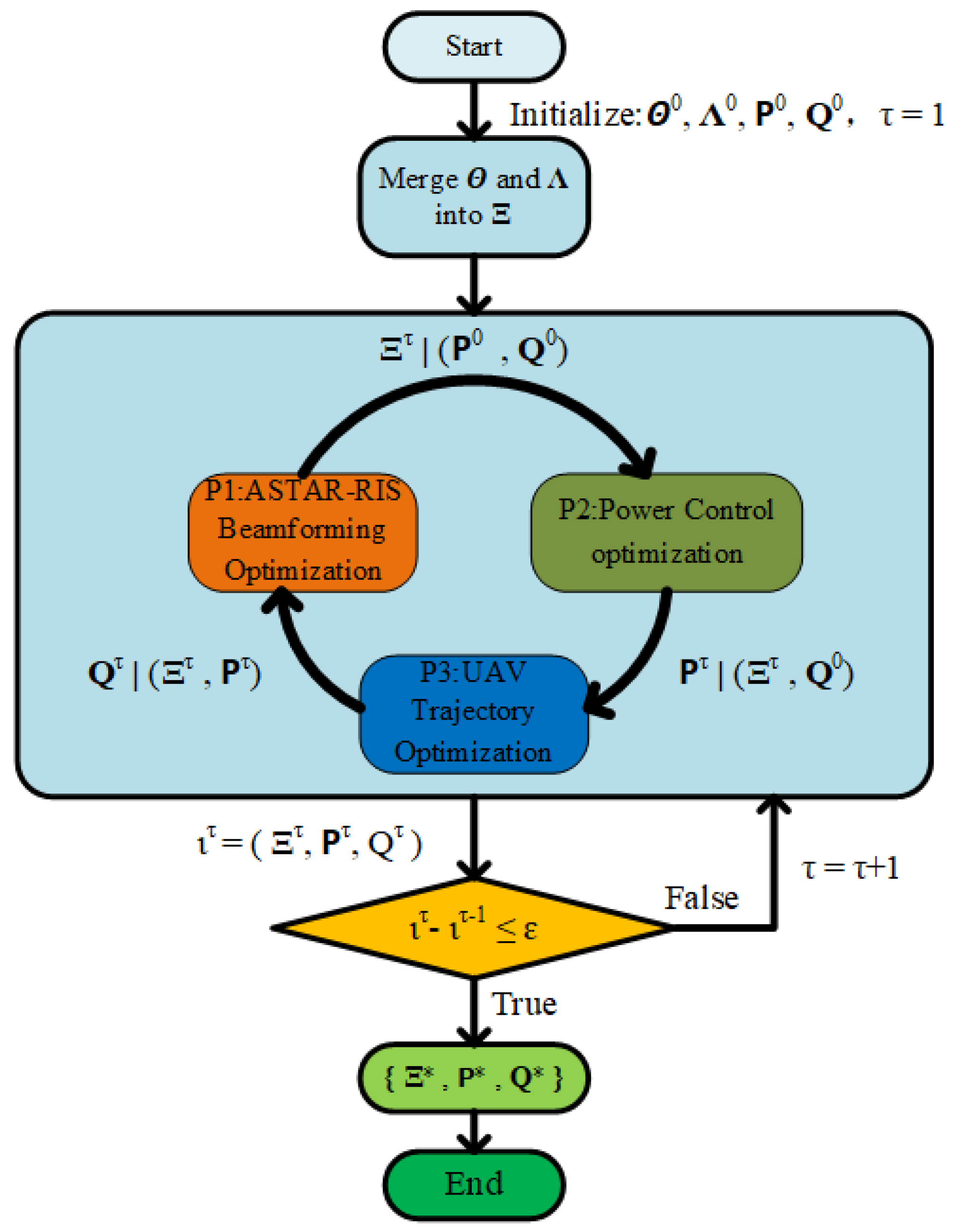
. We then propose an AO algorithm to solve them sequentially, whose flow diagram is illustrated in
Figure 2.
In particular, we begin by fixing the UAV trajectories and to solve the STAR-RIS beamforming subproblem, obtaining . Next, with and as inputs, we solve the power control subproblem to obtain . Finally, using and , we solve the UAV trajectory design subproblem to obtain . For the -th iteration, we evaluate the results ; if the convergence condition is not met, the algorithm proceeds to the next iteration. Otherwise, the final results are obtained.
4.1. STAR-RIS Beamforming Optimization
For given
and
, the optimization problem for the active STAR-RIS beamforming variables
can be formulated as
For ease of expression, we have made the following substitutions:
where
,
,
. Additionally, we define
. To tackle the non-convex problem, we introduce the relaxation vector
,
, where
and
are respectively defined as
Therefore, the transmission rate of SN
i can be rewritten as
We can then derive a local lower bound of Equation (
31) using first-order Taylor expansion, and replace the original optimization variables with convex lower bounds. The mathematical expressions are given as follows:
where
and
represent the given local points corresponding to
and
, respectively, in the
-th iteration of the SCA.
Furthermore, by introducing slack variables
and
, the original optimization problem can be reformulated as
Since the aforementioned optimization problem still contains rank-one constraints, we employ SDP to address this issue. First, the eigenvalue decomposition of
can be formulated as
where
,
, and
denote unitary matrices;
and
denote diagonal matrices with eigenvalues of
and
, respectively.
However, the optimal solution obtained via SDP may not satisfy the rank-one constraint. To deal with this problem, we introduce Gaussian randomization to derive a high-quality feasible solution. Specifically, for
, we first construct a suboptimal solution using Gaussian randomization, expressed as
, where
is a Gaussian random vector. Thus, the suboptimal transmission matrix can be derived as
For
, we still construct a suboptimal solution using Gaussian randomization, expressed as
, where
is a Gaussian random vector. Thus, the suboptimal transmission matrix can be derived as
To reduce the overhead introduced by Gaussian randomization after SDP relaxation, we implement a candidate screening mechanism during the randomization process. Specifically, we perform rounds of Gaussian randomization to generate candidate beamforming vectors. For each candidate, we compute the corresponding objective value and feasibility. Instead of evaluating all candidates exhaustively, we retain only those candidates whose objective values exceed a predefined performance threshold. This top-k screening significantly reduces the evaluation overhead while maintaining near-optimal performance.
The initial problem has now been converted into an SDP problem, allowing for efficient resolution using optimization platforms such as CVX.
4.2. Power Control Optimization
Since the STAR-RIS beamforming has been obtained in the previous subsection, it can be treated as a constant. By further fixing the UAV trajectory
Q, the formulation of the power control subproblem is given by
It can be observed that
is non-convex, and the constraints include non-convex terms. To address this challenge, we employ FP theory to transform the nonlinear objective into a subtractive form. By introducing an auxiliary variable
, the objective function can be equivalently rewritten as follows:
To facilitate further simplification of the objective function, an auxiliary variable
is introduced as follows:
Next, we let
and reformulate
into a subtractive form as follows:
where
Since
is a differentiable convex function, we can derive its upper bound using first-order Taylor expansion:
where
can be expressed as
where
For constraint (
37b), we can reformulate it as
Similarly, for constraint (
37c), we can reformulate it as
Consequently, the problem
can be reformulated as the following convex optimization problem:
The above subproblem is convex and can be efficiently solved using CVX solvers.
4.3. UAV Trajectory Optimization
When the above two subproblems have been solved, the corresponding UAV trajectory optimization problem becomes
It can be observed that the aforementioned problem increases with
, implying that optimizing
is equivalent to optimizing
. However, this form of the objective function is difficult to handle directly. To address this, we first derive
as
where
,
,
and
. We then introduce the slack variable
and
. We then reformulate
to explicitly express its coupling relationship with
Q,
where
,
and
.
Accordingly, the optimization problem
can be re-expressed as
If the equality conditions for
and
are satisfied, then problems
and
are equivalent. However,
remains a non-convex optimization problem. To address this, we employ Taylor’s theorem to obtain the first-order Taylor approximations of
and
at the
-th iteration of the SCA procedure, as follows:
where
can be expressed as follows:
Let
and
;
,
and
can be expressed as follows:
Similarly, we proceed to apply first-order Taylor approximations to
and
as follows:
Replacing
by
, the UAV trajectory design problem can be recast into the following optimization form:
Since Problem is convex, it can be effectively addressed using the CVX optimization toolbox.
4.4. Overall Algorithm and Complexity Analysis
The original optimization problem is first decomposed into three subproblems via BCA, after which an efficient AO-based algorithm is developed to solve it iteratively. The algorithm begins by selecting an initial feasible solution, then sequentially (1) solves the beamforming subproblem via SDP, (2) solves the power allocation subproblem using FP theory with the obtained beamforming solution as input, and (3) addresses the UAV trajectory subproblem through SCA incorporating both beamforming and power allocation results. Each iteration calculates current energy efficiency before alternately optimizing all three subproblems, continuing until convergence or reaching maximum iterations. This iterative refinement process ensures progressive system performance enhancement, with the complete AO algorithm for active STAR-RIS-assisted UAV-NOMA data collection detailed in Algorithm 1.
| Algorithm 1: AO algorithm for active STAR-RIS-assisted UAV-NOMA data collection |
| Input: . |
| - 1:
Initialize the number of initial iteration , set the tolerance , merge into , calculate . - 2:
repeat - 3:
Solve the problem to update with given . - 4:
Solve the problem to update with given . - 5:
Solve the problem to update with given . - 6:
Calculate the DCCR and transmission rate . - 7:
Update . until - 8:
Return the optimal solution .
|
It should be noted that although the complexity analysis in this work is based on a sequential computation model to provide a unified expression of the theoretical computational burden across modules, several components in practice exhibit significant parallelization potential. Proper parallel processing can effectively reduce the overall runtime. However, this strategy typically comes with increased development complexity and additional hardware resource requirements, such as multi-core CPU or GPU clusters. It also relies on the support of high-performance computing platforms, which may raise the overall system deployment cost.
The computational complexity of Algorithm 1 is analyzed by evaluating each of its subproblems individually. First, for the active STAR-RIS beamforming subproblem, which is solved as a SDP problem using CVX under the constraint of an positive semidefinite matrix, the complexity is given by , where is the non-negative accuracy parameter. Similarly, the complexity of the power allocation subproblem can be expressed as . The complexity of the UAV trajectory optimization subproblem is given by . Thus, the overall computational complexity of Algorithm is , where denotes the total iterations for the AO algorithm convergence.
5. Numerical Results
In this subsection, we conduct comprehensive simulations to evaluate the performance of the proposed USR-assisted data collection algorithm. Unless otherwise specified, the simulation parameters are provided in
Table 2.
5.1. Simulation Setups
In the simulation scenario, the positions of SNs are randomly generated within a 300 × 300 m rectangular central area. We refer to our proposed solution as USR-NOMA. To evaluate the effectiveness of the proposed USR-NOMA scheme, we introduce the following baseline schemes for comparison:
P-USR-NOMA: In this scheme, the proposed active ASTAR-RIS is replaced with a passive STAR-RIS while maintaining the MS operation mode.
UR-NOMA: This scheme replaces the ASTAR-RIS in the proposed solution with a conventional RIS for assisted data collection. It can be regarded as a special case of P-USR-NOMA operating in MS mode, where all reflecting elements are fixed in either R mode or T mode. And the RIS elements in this scheme are fixed in T mode.
USR-OMA: In this scheme, the OMA protocol is applied to the ASTAR-RIS system, where orthogonal resource blocks are allocated. Specifically, frequency-division multiple access (FDMA) is used to avoid interference.
RND-BF-USR-NOMA: In this scheme, only the UAV trajectory and SN power control are optimized, while the ASTAR-RIS beamforming is randomly configured.
FP-USR-NOMA: In this scheme, only the UAV trajectory and beamforming are optimized. The SNs transmit at fixed power levels.
When the number of STAR-RIS components significantly increases, the solution time increases dramatically, and using Gaussian randomization to evaluate the objective function also incurs considerable computational costs. To demonstrate the effectiveness of the screening algorithm,
Table 3 presents a performance comparison of Algorithm 1 after each round of SDP + Gaussian randomization and SDP + screening Gaussian randomization under M =
. We performed Gaussian randomization operations for
rounds. To reduce related costs, we adopted the screening mechanism and only retained the candidate vectors ranked in the top
based on their target scores. This significantly reduced the complexity of the randomization step, thereby significantly accelerating the entire process without compromising performance.
5.2. Convergence and Robustness Analysis
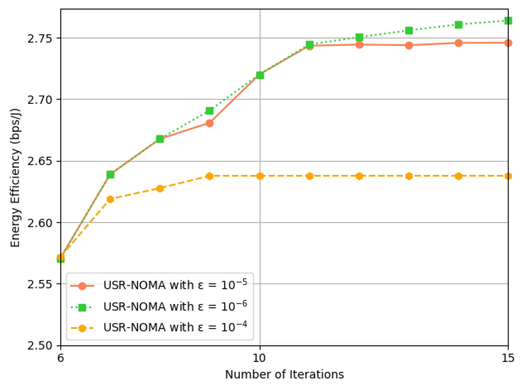
First, As shown in
Figure 3, we compared the convergence value
. Other experimental parameters were set as
, and
. It can be seen that when
to
, convergence was achieved in just two rounds, and the EE performance increased by 3.7%, equivalent to a 1.9% improvement in performance per round of iteration. When
, the EE performance only increased by 0.8%, and the number of iteration rounds significantly increased. In conclusion, in the following experiments, in order to balance performance and convergence speed, we set the value of
.
As shown in
Figure 4, we investigated the convergence of the proposed AO algorithm for UAV trajectory, beamforming, and power allocation, comparing it with three baseline scenarios. The results demonstrate that the proposed algorithm USR-NOMA converges within 11–12 iterations, and all schemes eventually reach stability, verifying the feasibility and effectiveness of the proposed model and solution. Furthermore, the performance degradation under the P-USR-NOMA scheme proves that active STAR-RIS can overcome the weak performance gain caused by multiplicative fading in long-distance scenarios. The UR-NOMA scheme demonstrates that STAR-RIS can achieve higher degrees of freedom and enhance overall system performance by enabling full-space coverage through simultaneous transmission and reception. Notably, the significantly reduced performance under the USR-OMA scheme occurs because, in high-throughput scenarios, SNs with poor channel conditions cannot transmit data due to limited orthogonal resources. This clearly indicates the necessity of applying NOMA in this system.
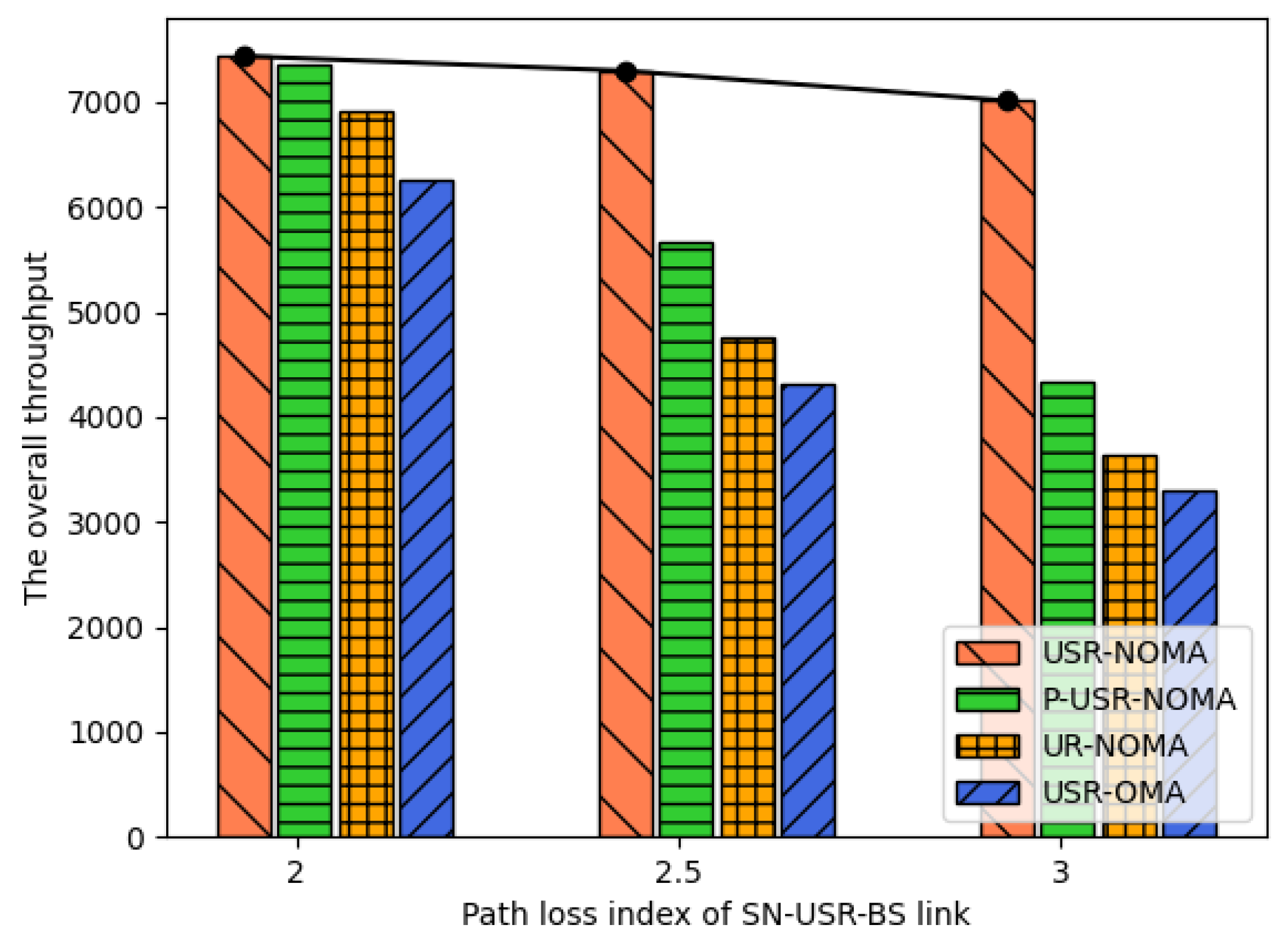
Figure 5 illustrates the variation in total throughput of different schemes as the path loss exponent of the SN-USR-BS link increases. The simulation parameters are set with the number of reflecting elements
, time slots
, and SNs
. As clearly shown, when the path loss exponent increases, the path loss of the SN-USR-BS link correspondingly increases, leading to a declining trend in system throughput across all four schemes. Notably, while the three baseline schemes exhibit significant degradation with increasing path loss exponent, the proposed USR-NOMA scheme demonstrates more gradual performance deterioration. This robustness stems from the active STAR-RIS’s capability to mitigate path loss through amplification, thereby compensating for harsh propagation conditions. The results validate our scheme’s superior performance in complex propagation environments. For subsequent simulations, unless otherwise specified, the path loss exponent is set to 2 while keeping other parameters unchanged.
5.3. UAV Trajectory Under Different Schemes
Figure 6 illustrates the trajectories of the three schemes after multiple iterations. Under the USR-NOMA scheme, the USR initially tends to collect data from edge devices to ensure DCCR, and compared with the P-USR-NOMA scheme, the USR flies farther away from the BS. This behavior occurs because the active STAR-RIS provides improved coverage capability by overcoming the relatively weak performance gain from multiplicative fading in long-distance scenarios. Additionally, it can be observed that the proposed scheme’s trajectory generally remains longer in the central region, a phenomenon that is more pronounced in the P-USR-NOMA scheme. For the UR-NOMA scheme, since the conventional RIS can only transmit data, the USR tends to fly toward the edge and stay closer to the BS to maximize the number of served SNs. While this approach sacrifices some DCCR compared to the STAR-RIS schemes, it ensures better signal quality reception at the BS.
5.4. Effect of Number of Reflecting Elements
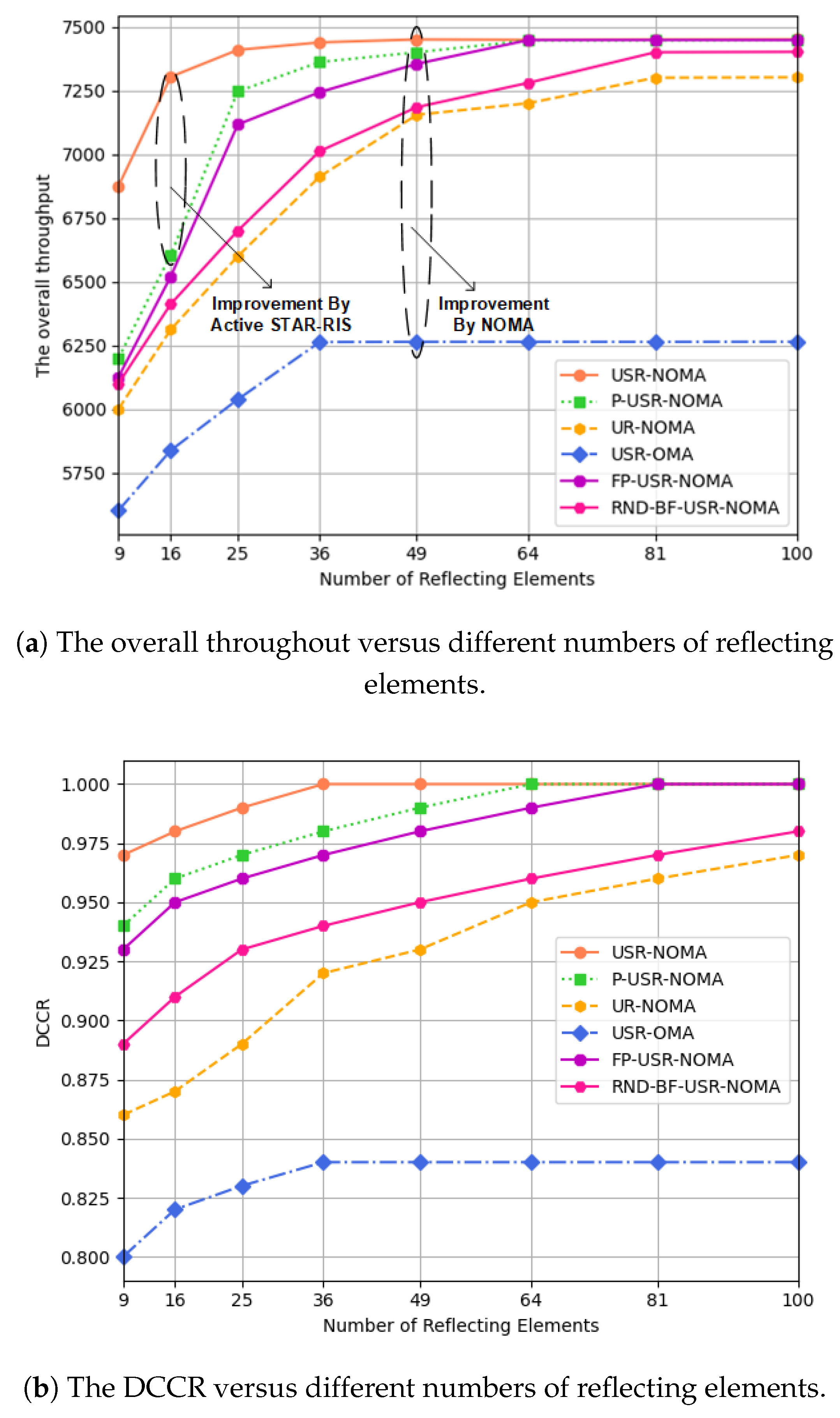
Figure 7a demonstrates the impact of different numbers of reflecting elements on throughput for both the proposed scheme and benchmark schemes. The results indicate that all schemes exhibit performance improvement with increasing reflecting elements, as more phase shifters enable the USR to better forward collected data to the BS, thereby enhancing channel gain. This improved channel gain subsequently boosts the SIC decoding capability at NOMA receivers, though such improvement has an upper limit in this system. In the proposed USR-NOMA scheme, throughput reaches its maximum at M = 36, as further increasing reflecting elements would lead to increased overall weight of the USR and non-negligible energy consumption by the RIS controller, demonstrating that our scheme achieves optimal performance with relatively few reflecting elements. Furthermore, compared to OMA schemes, NOMA schemes benefit more significantly from additional reflecting elements, showing 15–20% throughput improvement when
. The performance advantage of USR-NOMA over FP-USR-NOMA underscores the necessity of power optimization, since the decoding and communication constraints require simultaneous optimization of SNs’ transmission power and UAV trajectory.
Figure 7b illustrates the impact of different numbers of reflecting elements on DCCR for both the proposed scheme and benchmark schemes. In the proposed scheme, DCCR reaches 100% when the number of reflecting elements increases to 36, while the P-USR-NOMA and FP-USR-NOMA schemes require
and
, respectively, to achieve the same performance, demonstrating the effectiveness of the active STAR-RIS solution and AO algorithm as they require fewer reflecting elements to attain optimal performance. Furthermore, the other three schemes struggle to achieve complete data collection. In the RND-BF-USR-NOMA scheme, randomly configured beamforming leads to potential data loss due to signal fluctuations or misaligned beams, significantly reducing collection efficiency. The UR-NOMA scheme faces limitations from conventional RIS technology, making it difficult to accomplish comprehensive data collection with limited energy. For the USR-OMA scheme, the constrained orthogonal resources prevent edge SNs with poor channel conditions from accessing the network, and merely increasing reflecting elements cannot improve DCCR performance.
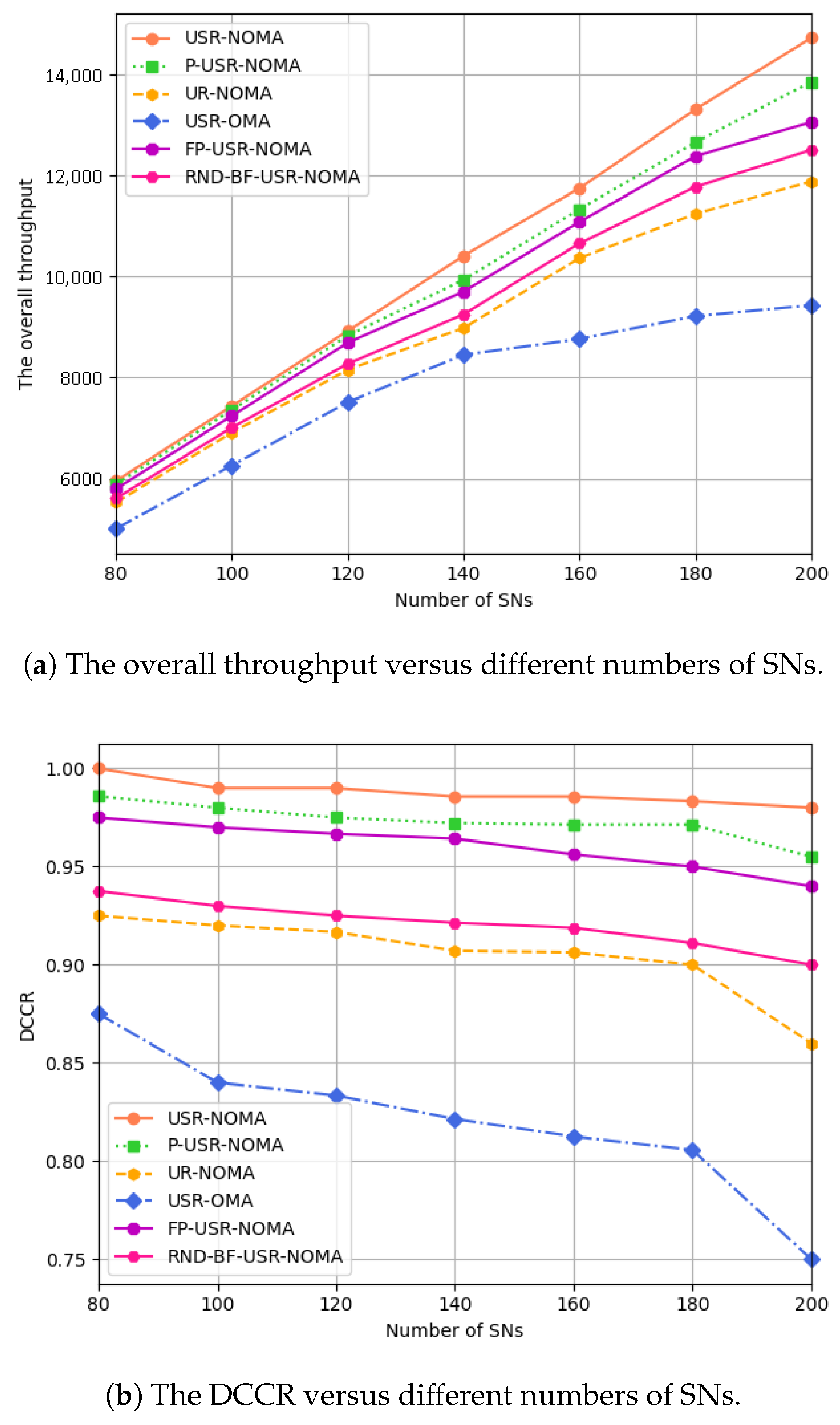
5.5. Effect of Number of SNs
Figure 8a illustrates the performance comparison between the proposed scheme and baseline schemes across varying numbers of SNs. As the number of SNs increases, all schemes exhibit enhanced EE performance, with the USR-NOMA scheme consistently achieving superior results. The performance advantages over P-USR-NOMA, FP-USR-NOMA, and RND-BF-USR-NOMA schemes stem from the active STAR-RIS and joint optimization algorithm. In contrast, the EE gains of the OMA scheme show limited sensitivity to increasing SNs and eventually converge when the number of SNs reaches a certain threshold. This occurs because OMA allocates orthogonal resources among users, while NOMA serves multiple users simultaneously on the same resource block through superposition transmission, thereby enhancing spectral efficiency. The results confirm that NOMA schemes are more suitable for high-density communication scenarios.
Figure 8b illustrates the impact of increasing SN quantity on DCCR for both the proposed scheme and benchmark schemes. As shown, all schemes exhibit declining DCCR trends with growing SN deployment density, primarily due to intensified inter-network interference that significantly degrades performance and complicates both data transmission and SIC decoding. Nevertheless, the proposed USR-NOMA scheme maintains superior performance with approximately 97% DCCR even at
, outperforming other alternatives. This robustness stems from the active STAR-RIS’s capability to mitigate high interference through signal amplification, effectively compensating for harsh propagation conditions. The scheme demonstrates a notable 22% improvement over OMA solutions, particularly highlighting NOMA’s advantages in large-scale transmission scenarios. The results collectively validate both the interference resilience of our approach and NOMA’s superior scalability in dense network environments.
6. Conclusions and Future Work
This study addresses the data collection challenge in active STAR-RIS-assisted UAV-enabled NOMA networks. Given the intricate wireless propagation conditions in urban environments, we propose a UAV-mounted active STAR-RIS framework to augment the flexibility of data collection operations. Prioritizing data integrity, we introduce the DCCR metric as a key performance indicator. To optimize system performance, we formulate a joint optimization problem integrating STAR-RIS beamforming, UAV trajectory planning, and SN power allocation, with the objective of maximizing EE. To tackle the inherent coupling of optimization variables, we design an AO-driven solution framework that partitions the original problem into three solvable subproblems, addressed through iteration. The simulation results show that, under the same settings, the proposed algorithm achieves a performance improvement of 10% to 55% over other baseline algorithms after convergence. Moreover, it enhances the DCCR by 22% and the EE by 15% compared to the OMA scheme. In the future, we intend to incorporate more realistic A2G channel models and imperfect CSI, account for phase estimation errors, and evaluate performance under diverse obstacle scenarios. And we plan to further incorporate the beam coverage angle model of the STAR-RIS and account for the non-ideal effects of the incident/transmission and reflection angles on the reflection/transmission gains, in order to enhance the physical consistency and engineering feasibility of the model. These extensions will facilitate a more holistic assessment of system robustness in practical deployment.
Author Contributions
Conceptualization, Y.Z. and Y.H.; methodology and data curation, Y.Z.; validation, Y.Z., Y.H. and D.L.; formal analysis, Y.Z. and Y.H.; investigation, Y.Z., Y.H., D.L. and C.L.; writing—original draft preparation, Y.Z.; writing—review and editing, Y.Z. and Y.H.; supervision, Y.H., D.L., C.L. and X.F.; project administration, Y.H., C.L. and X.F.; funding acquisition, Y.H. and C.L. All authors have read and agreed to the published version of the manuscript.
Funding
This work was supported in part by the National Natural Science Foundation of China under Grant (62002022, 62202054) and the Fundamental Research Funds for the Central Universities (No. BLX201921, No. 2021ZY88).
Data Availability Statement
Data are contained within the article.
Conflicts of Interest
The authors declare no conflicts of interest. The founding sponsors had no role in the design of the study; in the collection, analyses, or interpretation of data; in the writing of the manuscript; or in the decision to publish the results.
References
- Wang, D.; Yuan, L.; Pang, L.; Xu, Q.; He, Y. Age of Information-Inspired Data Collection and Secure Upload Assisted by the Unmanned Aerial Vehicle and Reconfigurable Intelligent Surface in Maritime Wireless Sensor Networks. Drones 2024, 8, 267. [Google Scholar] [CrossRef]
- Diao, D.; Wang, B.; Guo, R. Secure and Energy-Efficient Configuration Strategies for UAV-RIS System with Uplink NOMA. Drones 2025, 9, 289. [Google Scholar] [CrossRef]
- Shen, X.; Gu, L.; Yang, J.; Shen, S. Energy Efficiency Optimization for UAV-RIS-Assisted Wireless Powered Communication Networks. Drones 2025, 9, 344. [Google Scholar] [CrossRef]
- Liu, J.; Zhang, H. Throughput Optimization in Aerial RIS-Assisted Networks with 3D Imperfect Reflection. IEEE Trans. Veh. Technol. 2025, 74, 10510–10523. [Google Scholar] [CrossRef]
- Tyrovolas, D.; Mekikis, P.V.; Tegos, S.A.; Diamantoulakis, P.D.; Liaskos, C.K.; Karagiannidis, G.K. Energy-Aware Design of UAV-Mounted RIS Networks for IoT Data Collection. IEEE Trans. Commun. 2023, 71, 1168–1178. [Google Scholar] [CrossRef]
- Zhao, S.; Gong, S.; Gu, B.; Li, L.; Lyu, B.; Thai Hoang, D.; Yi, C. Exploiting NOMA Transmissions in Multi-UAV-Assisted Wireless Networks: From Aerial-RIS to Mode-Switching UAVs. IEEE Trans. Wirel. Commun. 2025, 24, 2530–2544. [Google Scholar] [CrossRef]
- Zhang, X.; Zhang, H.; Sun, K.; Long, K.; Li, Y. Human-Centric Irregular RIS-Assisted Multi-UAV Networks with Resource Allocation and Reflecting Design for Metaverse. IEEE J. Sel. Areas Commun. 2024, 42, 603–615. [Google Scholar] [CrossRef]
- Li, J.; Yang, L.; Wu, Q.; Lei, X.; Zhou, F.; Shu, F.; Mu, X.; Liu, Y.; Fan, P. Active RIS-Aided NOMA-Enabled Space- Air-Ground Integrated Networks with Cognitive Radio. IEEE J. Sel. Areas Commun. 2025, 43, 314–333. [Google Scholar] [CrossRef]
- Sui, Z.; Ngo, H.Q.; Matthaiou, M.; Hanzo, L. Performance Analysis and Optimization of STAR-RIS-Aided Cell-Free Massive MIMO Systems Relying on Imperfect Hardware. IEEE Trans. Wirel. Commun. 2025, 24, 2925–2939. [Google Scholar] [CrossRef]
- Katwe, M.; Singh, K.; Clerckx, B.; Li, C.P. Improved Spectral Efficiency in STAR-RIS Aided Uplink Communication Using Rate Splitting Multiple Access. IEEE Trans. Wirel. Commun. 2023, 22, 5365–5382. [Google Scholar] [CrossRef]
- Singh, C.K.; Kumar, D.; Lehtomäki, J.; Khan, Z.; Latva-Aho, M.; Upadhyay, P.K. Robust UAV-Integrated Active STAR-RIS RSMA Networks: Analysis with Deep Learning Techniques. IEEE Trans. Veh. Technol. 2025, 74, 8297–8302. [Google Scholar] [CrossRef]
- Lei, J.; Zhang, T.; Mu, X.; Liu, Y. NOMA for STAR-RIS Assisted UAV Networks. IEEE Trans. Commun. 2024, 72, 1732–1745. [Google Scholar] [CrossRef]
- Zhao, J.; Xu, Q.; Mu, X.; Liu, Y.; Zhu, Y. Aerial Active STAR-RIS-Aided IoT NOMA Networks. IEEE Internet Things J. 2025, 12, 9525–9538. [Google Scholar] [CrossRef]
- Wang, Q.; Guo, S.; Wu, C.; Xing, C.; Zhao, N.; Niyato, D.; Karagiannidis, G.K. STAR-RIS Aided Covert Communication in UAV Air-Ground Networks. IEEE J. Sel. Areas Commun. 2025, 43, 245–259. [Google Scholar] [CrossRef]
- Aung, P.S.; Nguyen, L.X.; Tun, Y.K.; Han, Z.; Hong, C.S. Aerial STAR-RIS Empowered MEC: A DRL Approach for Energy Minimization. IEEE Wirel. Commun. Lett. 2024, 13, 1409–1413. [Google Scholar] [CrossRef]
- Liu, Y.; Mu, X.; Xu, J.; Schober, R.; Hao, Y.; Poor, H.V.; Hanzo, L. STAR: Simultaneous Transmission and Reflection for 360° Coverage by Intelligent Surfaces. IEEE Wirel. Commun. 2021, 28, 102–109. [Google Scholar] [CrossRef]
- Mu, X.; Liu, Y.; Guo, L.; Lin, J.; Schober, R. Simultaneously Transmitting and Reflecting (STAR) RIS Aided Wireless Communications. IEEE Trans. Wirel. Commun. 2022, 21, 3083–3098. [Google Scholar] [CrossRef]
- Xu, J.; Liu, Y.; Mu, X.; Schober, R.; Poor, H.V. STAR-RISs: A Correlated T&R Phase-Shift Model and Practical Phase-Shift Configuration Strategies. IEEE J. Sel. Top. Signal Process. 2022, 16, 1097–1111. [Google Scholar] [CrossRef]
- Han, Z.; Swindlehurst, A.L.; Liu, K.R. Optimization of MANET connectivity via smart deployment/movement of unmanned air vehicles. IEEE Trans. Veh. Technol. 2009, 58, 3533–3546. [Google Scholar] [CrossRef]
| Disclaimer/Publisher’s Note: The statements, opinions and data contained in all publications are solely those of the individual author(s) and contributor(s) and not of MDPI and/or the editor(s). MDPI and/or the editor(s) disclaim responsibility for any injury to people or property resulting from any ideas, methods, instructions or products referred to in the content. |
© 2025 by the authors. Licensee MDPI, Basel, Switzerland. This article is an open access article distributed under the terms and conditions of the Creative Commons Attribution (CC BY) license (https://creativecommons.org/licenses/by/4.0/).


