Article

A Semi-Autonomous Aerial Platform Enhancing Non-Destructive Tests

by
Simone D’Angelo
1,2,*,
Salvatore Marcellini
3,
Alessandro De Crescenzo
4,
Michele Marolla
3,
Vincenzo Lippiello
1,4 and
Bruno Siciliano
1
1
PRISMA Lab, Department of Engineering and Information Technology, University of Naples Federico II, 80125 Naples, Italy
2
Centro Servizi Metrologici e Tecnologici Avanzati (CeSMA), University of Naples Federico II, Corso Nicolangelo Protopisani, 80146 Naples, Italy
3
Innovation Labs, Leonardo S.p.A., 00195 Rome, Italy
4
Neabotics S.r.l., 80124 Naples, Italy
*
Author to whom correspondence should be addressed.
Drones 2025, 9(8), 516; https://doi.org/10.3390/drones9080516
Submission received: 3 June 2025 / Revised: 11 July 2025 / Accepted: 17 July 2025 / Published: 23 July 2025
(This article belongs to the Special Issue Unmanned Aerial Manipulation with Physical Interaction)

Abstract

The use of aerial robots for inspection and maintenance in industrial settings demands high maneuverability, precise control, and reliable measurements. This study explores the development of a fully customized unmanned aerial manipulator (UAM), composed of a tilting drone and an articulated robotic arm, designed to perform non-destructive in-contact inspections of iron structures. The system is intended to operate in complex and potentially hazardous environments, where autonomous execution is supported by shared-control strategies that include human supervision. A parallel force–impedance control framework is implemented to enable smooth and repeatable contact between a sensor for ultrasonic testing (UT) and the inspected surface. During interaction, the arm applies a controlled push to create a vacuum seal, allowing accurate thickness measurements. The control strategy is validated through repeated trials in both indoor and outdoor scenarios, demonstrating consistency and robustness. The paper also addresses the mechanical and control integration of the complex robotic system, highlighting the challenges and solutions in achieving a responsive and reliable aerial platform. The combination of semi-autonomous control and human-in-the-loop operation significantly improves the effectiveness of inspection tasks in hard-to-reach environments, enhancing both human safety and task performance.

1. Introduction

The growing interest in unmanned aerial vehicles (UAVs) for non-destructive testing (NDT) stems from their ability to access confined or hazardous environments without requiring scaffolding, cranes, or rope access. This paradigm shift not only reduces inspection time, logistical complexity, and operational costs but also significantly enhances operator safety by limiting human exposure to high-risk areas such as elevated structures, enclosed spaces, or toxic zones [1,2]. Among various NDT methods, techniques like ultrasonic testing demand direct contact with the surface, posing additional challenges for aerial platforms, including the need to regulate contact forces precisely and maintain flight stability during interaction.
To address these challenges, recent works have investigated contact-aware multirotor systems capable of performing inspection and maintenance tasks while interacting safely with the environment [3]. In this context, the integration of semi-autonomous functionalities further extends UAV adaptability in industrial scenarios, allowing them to autonomously execute routine operations while leaving room for human intervention in critical phases. This hybrid human–machine approach merges the precision and repeatability of autonomous flight with the judgment and flexibility of human operators, enabling safer and more intelligent inspection workflows [4].
Building on previous work [5], this paper presents a fully customized aerial manipulator designed for contact-based NDT inspections. The proposed platform combines an omnidirectional tilting multirotor with an actuated robotic arm and a specialized inspection tool (see Figure 1). The system is capable of autonomously navigating industrial facilities to reach target inspection points, where a remote pilot can activate dedicated control modes through a radio controller. To ensure flight stability during contact, a movable battery carriage dynamically adjusts the platform’s center of mass.
A state machine governs the task execution, coordinating all routines from navigation to inspection. Time-of-flight (ToF) sensors on the drone base provide real-time information on the distance and orientation relative to the work surface, supporting an autonomous approach strategy. The robotic arm transitions from a “home” configuration to the inspection pose and regulates contact using a parallel force–impedance control scheme. After task completion, the system gradually reduces interaction forces and safely returns to the home configuration, allowing the operator to repeat measurements or land the drone as needed.
This paper details the mechanical and control design of the aerial platform and validates its performance through experiments conducted in both indoor and outdoor industrial scenarios, offering insights for future developments of semi-autonomous UAV systems for NDT applications.

2. Related Works

The literature relevant to this research is structured into two main subsections. The first explores the control challenges inherent to inspection tasks, with a particular emphasis on the methodologies and technologies that enable precise, stable, and reliable execution. The second focuses on teleoperation and shared-control paradigms, highlighting their significance in fostering effective human–machine collaboration and enhancing the overall efficiency and robustness of inspection systems.

2.1. In-Contact Inspections

Robotic systems tailored to NDT have evolved significantly, encompassing a broad range of solutions, including mobile ground platforms [6], internal climbing robots for confined space inspections [7], and exterior climbing systems [8]. Despite this progress, achieving stable flight during physical interaction with the environment remains a key challenge. To address this, different solutions were investigated, leading to an increased heterogeneity in aerial manipulation [9]: various UAVs equipped with sensorized sticks have been developed [10,11], exploiting advanced control strategies to estimate surface properties and perform complex contact tasks, effectively combining force sensing with full-pose control to operate in unstructured environments. Examples of UAVs capable of regulating interaction forces for surface tasks include systems designed for writing on planar surfaces, later extended to arbitrary geometries using visual feedback [12,13]. Moreover, fully actuated aerial platforms have also been developed to manage contact interactions more effectively, employing selective impedance control and parallel force-motion strategies [14]. Further advancements are seen in [15], where non-linear model predictive control (NMPC) is employed to handle different flight phases and optimize force/motion tracking; direct force control with online task optimization is instead presented in [16] satisfying different control objectives (e.g., interaction force, the position of the end-effector (E-E), the full pose of the robot, etc.) and hard constraints to ensure the stability of the system and the feasibility of the problem solution.
Growing interest is demonstrated finally in UAVs equipped with tilted or tilting thrusters [17]: these platforms have proven effective in maintaining stability across varying orientations—an essential requirement for complex inspection tasks in industrial environments. However, platforms with fixed-tilt probes, although suitable for flat or unobstructed surfaces [18], fall short when operating near intricate structures such as pylons or T-shaped beams. This limitation can be addressed by integrating a tilting aerial platform with a fully actuated robotic arm [19,20], significantly enhancing maneuverability and allowing remote operators to execute tasks with a level of precision approaching that of on-site human technicians [21].

2.2. Teleoperation and Shared-Control

Despite the growing interest in autonomous aerial robotic systems, fully autonomous operation remains challenging in unpredictable environments, especially in contexts constrained by strict safety regulations. As a result, teleoperation continues to be the most practical approach for executing contact-based inspection tasks with UAVs. These tasks, however, require the precise regulation of both motion and contact force, imposing significant cognitive and physical demands on human operators due to the mismatch in embodiment between humans and machines [22].
To address this, shared control has emerged as an effective paradigm, wherein autonomy supports human decision-making by offloading low-level control responsibilities [23,24]. This collaboration is particularly advantageous when dealing with high-dimensional systems [25,26] or during tasks involving complex operations such as orientation control [27]. Haptic feedback is often incorporated to provide intuitive cues about physical constraints acting on the robot, thus improving task execution [28].
Several teleoperation frameworks have been proposed to balance autonomy and user input. For instance, a bilateral force–feedback approach was introduced in [29], where the user controls free-flight motion and applies contact forces via a passive tool mounted on the UAV. However, this approach exposes the difficulty operators face in managing decoupled commands in omnidirectional systems, underscoring the need for more sophisticated teleoperation strategies [30]. A promising direction is offered by hierarchical shared control, such as in [31], where users can command sequences of actions with assigned priority levels, enabling more efficient interaction in complex tasks like aerial pick-and-place operations.

2.3. Contribution

This work builds upon our previous contribution presented at the 18th ISER [5], which introduced an early proof of concept for aerial contact inspection. Here, we extend that preliminary study by presenting a fully integrated system with substantial improvements in both hardware and software. Operating within the domain of aerial manipulation and NDT, we address a central question: how can a multirotor platform safely and reliably perform semi-autonomous contact-based inspection tasks in realistic environments?
To this end, we propose a complete aerial system that unifies a fully actuated multirotor, a lightweight robotic arm, and a mobile battery carriage for dynamic center-of-mass compensation. The platform is governed by a high-level shared-control framework, designed to coordinate autonomous task execution and human supervision while enforcing strict safety constraints through dedicated monitoring layers. In contrast to fragmented or simulation-only solutions in the literature, our system is experimentally validated—both indoors and outdoors—demonstrating stable physical interaction, repeatable ultrasonic measurements, and practical deployability in industrial scenarios. An overview of the system architecture is shown in Figure 2, while in the following, we analyze our contributions:
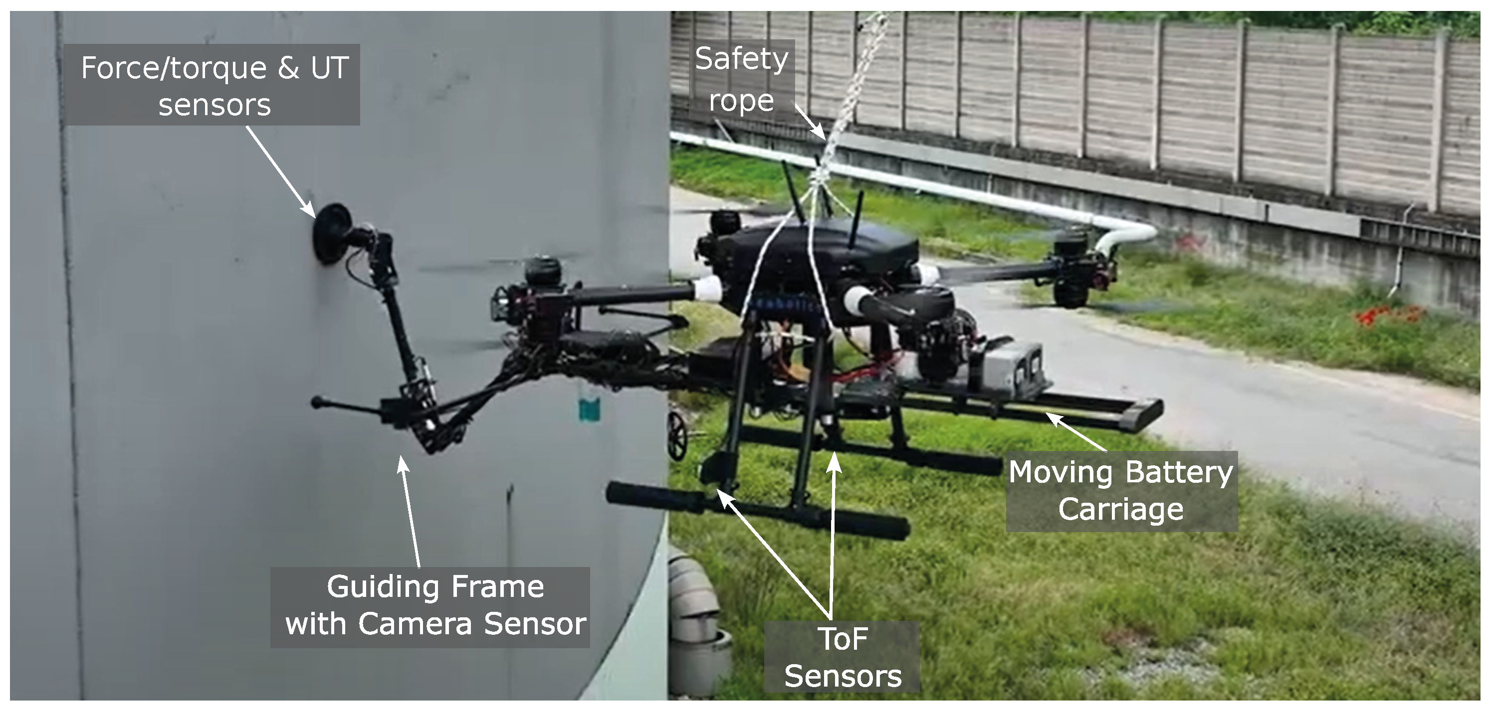
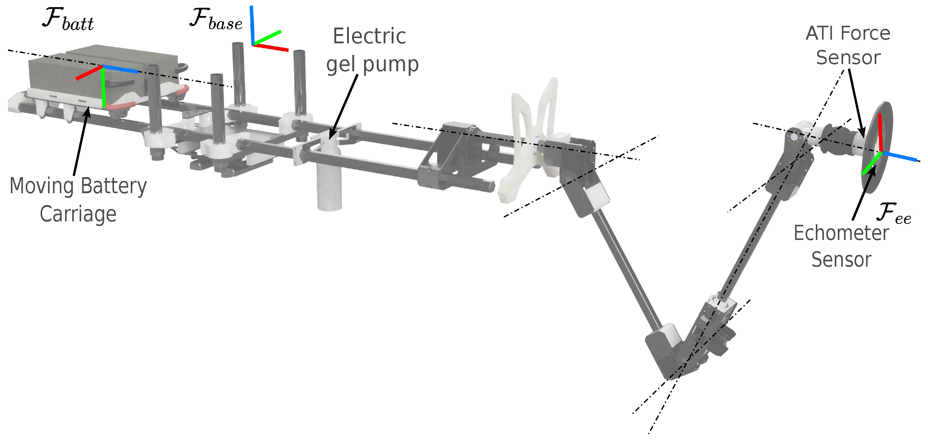
  • A multi-functional platform design: The paper’s primary contribution relies on the proposed platform design (see Figure 1). In the past, it has been presented solely in operational contexts. This paper now delves into the comprehensive detailing of its constituent components and the seamless hardware and software integration. This shift in focus is crucial, as it allows for a thorough exploration of how each platform component contributes to its overall functionality and performance. The aerial robot comprises an omnidirectional UAV combined with a fully actuated robotic arm. A key innovation is the mass-shifting mechanism, which dynamically and autonomously adjusts the drone’s CoM when the robotic arm extends. This feature ensures stability and maneuverability, which are crucial for maintaining control during contact-based inspections.
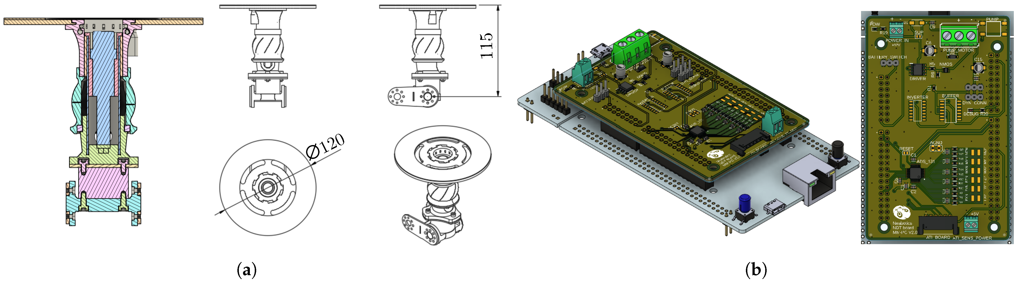
  • Different hardware and software enhancements: The platform’s hardware improvements include enhanced sensor suites for improved environmental awareness and task execution. The changes involve both sensors responsible for the navigation and the introduction of a different force sensor on the E-E tip. This is the reason at the basis of the new printed circuit board (PCB) development whose features are detailed in Section 3.2. On the software front, refinements to the control algorithms and the introduction of a robust state machine architecture ensure smoother operation and increased reliability during semi-autonomous missions.
  • A semi-autonomous control paradigm: The implemented control paradigm enables semi-autonomous operation, leveraging both automated routines and human intervention for optimal task execution. A state machine governs the operation, orchestrating transitions between different control modes based on real-time sensor feedback and operator commands. It ensures coherent and efficient operation by defining states for different phases of the inspection process, including initialization, task execution, and completion. This approach enhances flexibility and adaptability in varying operational scenarios, ensuring robust performance in dynamic industrial environments.
  • Sensor integration and feedback mechanisms: Critical to the platform’s functionality is the seamless integration of sensors for environment perception and task execution. High-precision sensors facilitate accurate localization, obstacle detection, and surface interaction monitoring. Real-time feedback from these sensors informs decision-making processes within the control system, enabling adaptive responses to environmental changes and operational contingencies.
Figure 2. System diagram. The main functional blocks of the system are highlighted: control modules (blue), actuation units (red), power supply components (violet), signal processing and electronic interfaces (yellow), and input devices (green).
Drones 09 00516 g002

3. System Overview

This paper investigates a telemanipulation system composed of a controller and a UAM deployed in an industrial setting. The manipulator is mounted beneath a UAV, and the entire task is executed during the drone’s flight. Moreover, considering that the robot typically moves slowly (or not at all) during a force control task, the UAM’s controller can be decoupled between the arm and flight controllers, thanks to the hypothesis of quasi-stationary flight during the task execution [32,33,34]. In the shared-control paradigm, the operator remotely directs the robot to complete specific tasks modifying the UAM behavior on the basis of a task state machine. An overview of the control architecture is depicted in Figure 3, highlighting both the decoupling between the flying platform and the manipulator and the E-E motion/force tracking. A monocular camera positioned on the guiding frame provides visual feedback to the operator, aiding in the determination of the relative pose between the UAV and the surface, and the commands are sent via a commercial radio controller (RC).
The endowed drone features a co-axial tilting octa-rotor design (see Figure 1): in this configuration, each pair of co-axial motors is connected to its dedicated and independent servo motor. This setup allows for the precise and independent control of each motor pair’s orientation, enhancing the drone’s maneuverability and stability during flight. The design enables the drone to perform complex movements and maintain a stable hover, even in challenging conditions. It is characterized by a commercial frame completely customized in mechanics and electronics. A standard Pixhawk flight controller board is the UAV core. The PX4 firmware was modified without using third-party tools. This improvement preserves important functionality, adding new capabilities. This letter starts from the results of [17,35], in which different custom PX4 firmware versions are presented.

3.1. Tilting UAM Mechatronic Development

The final version of the developed omnidirectional drone features a sophisticated actuation system designed to optimize performance for NDT applications. The system incorporates 8 T-Motor U7 280KV brushless motors (Blue Star Trading Limited, Nanchang, Jiangxi, China) for propulsion, 4 SAVOX SB-2292SG digital servomotors (SAVOX, JSP Group Intl BV, Olen, Belgium) for tilting, and 8 T-Motor CF P20×6 carbon fiber propellers (Blue Star Trading Limited, Nanchang, Jiangxi, China). Power is supplied with two 16,000 mAh Tattu LiPo batteries (Grepow Inc., Livermore, CA, United States) connected in parallel. This configuration increases both the overall stored energy and the maximum available discharge current, thereby extending the flight time and ensuring stable power delivery during high-demand maneuvers. To complete, motor control is managed using T-Motor F45A 32-bit ESCs (Blue Star Trading Limited, Nanchang, Jiangxi, China).
The drone’s omnidirectional tilting mechanism relies on four independent arms with adjustable tilt angles. Each co-axial motor pair is mounted on a rigid support fixed to the arm utilizing two ball bearings. Such support is then connected to the arm through a servomotor commanding the desired tilt angle.
An online simulator (eCalc [36]) is used to illustrate the performance of the finalized aerial platform, based on the selected configuration and equipment. The performance envelope of the selected design, including motor characteristics at full throttle, is depicted in Figure 4a. Under adverse wind conditions with speeds up to 25 km/h, the drone maintains a maximum flight time of around 10 min, with an unchanged range of 4 km. Compared to the initial prototype, this version exhibits a performance increase of up to 60% in critical operating scenarios. The evaluation assumes a take-off mass of approximately 12 kg. Under nominal conditions, this configuration yields a maximum flight endurance of 19 min and a total operational range of 4 km (see Figure 4b). The expected motor temperature during standard operation is approximately 57 °C, and the thrust-to-weight ratio is estimated to be 2.

3.2. Robotic Arm

The equipped robotic arm weighs approximately 1.5 kg while having a payload capacity of 1 kg. This payload capacity, which is small compared to that of other robotic arm solutions present in the market, is enough for carrying the measuring probe, and it allows the arm to be extremely lightweight and not overload the UAV (as confirmed by [37]). A commercial UT sensor acquires and processes data from a piezo-electric probe located inside the E-E, and a flange is placed on the tip to accommodate the surface that will be measured. Changing the shape of the flange, the arm can easily be adapted to different surfaces and curvatures.
The E-E is characterized by an NDT tool (see Figure 5a) featuring the 6-axis force/torque sensor, the UT sensor, the coupling-gel distribution ducts, a passive DoF and two-positions swivel coupling bracket.
To ensure accurate and reliable measurements, the ultrasound probe requires applying a thin layer of coupling gel between it and the surface to be inspected. The gel is pumped into a cavity in front of the sensor; before that, the sensor is pushed out in contact with the surface. This maneuver guarantees a uniform distribution of the gel, avoiding undesired leakages during the approaching maneuver. A DC motor drives a peristaltic pump to conduct a gel flow through appropriately sized rubber tubes up to the tool at the end of the arm. In the tool, a series of calibrated conduits allows the gel to escape, guaranteeing a homogeneous distribution on the terminal part before contact with the surface is inspected.

Moving Battery Carriage

With its motion, the arm modifies the system CoM: especially when fully extended, this can compromise the balancing of the UAV, increasing the stress on propellers and servomotors. This behavior can be compensated by moving the batteries to maintain the balance of the system and keep the CoM as close as possible to the center of the UAV. In particular, the batteries, with a total mass of 1.75 kg, are placed on a belt-driven carriage that moves the batteries of a displacement x b a t t given as follows:
x b a t t = x 0 , b a t t + K b a t t x g R ,
where x b a t t is the desired position of the batteries in B , x 0 , b a t t is the offset from the initialization, K b a t t is a properly tuned gain, and x g is the position of the arm CoM along the x B evaluated with the dynamic model of the arm. The concept is different from the one proposed in [38]: here, the moving mass is considered to compensate for the inertia changes and not to increase the friction to the environment.

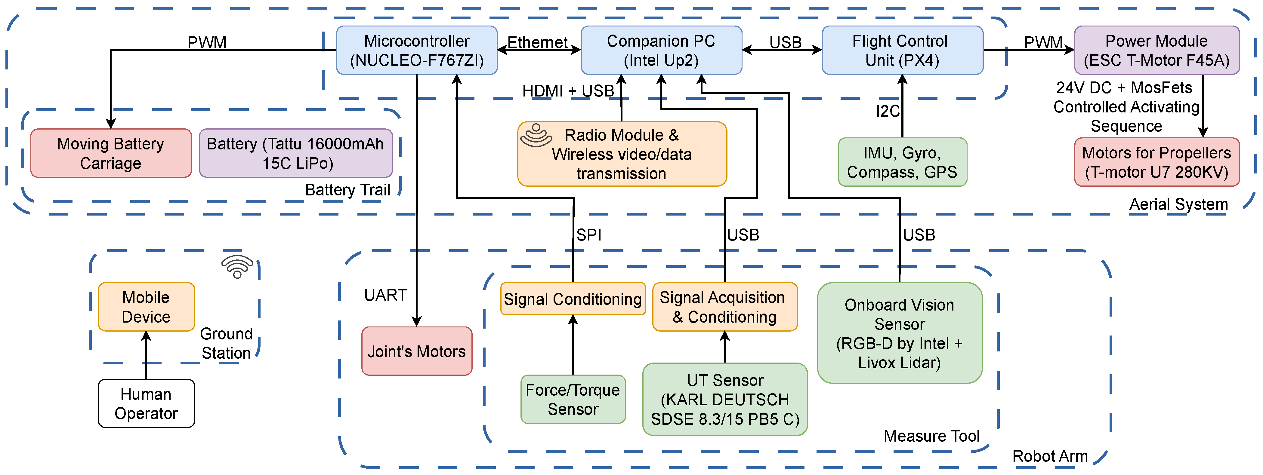
3.3. Electronics and Components

The robotic arm is actuated via Dynamixel servomotors, specifically the following: 1 MX-106, 2 MX-64, and 2 MX-28 models. Meanwhile, the battery carriage is actuated via an additional Dynamixel MX-28 servomotor (ROBOTIS Co., Ltd., Seoul, Republic of Korea). Both the robotic arm and the battery carriage are controlled via an onboard microcontroller, the STM32F767ZI (STMicroelectronics NV, Plan-les-Ouates, Switzerland), which is integrated with a PCB, as in Figure 5b.
This custom PCB is responsible for collecting and processing data from the new force and torque sensor, controlling the arm and battery carriage motors, and managing the gel pump. The changes made to the PCB include the integration of a new force/torque sensor on the E-E tip, the XJC-6F-D30-C, using an ADS131 analog-to-digital converter for data acquisition: this choice leads to a significant reduction in power consumption and a considerable decrease in both space and overall weight. The ADS131 is used to interface with the force sensor by reading and converting the minimal changes in electrical resistance produced by the sensor into understandable digital signals for the microcontroller. Its ability to detect such subtle variations enables the precise measurement of applied forces, ensuring high accuracy and sensitivity in readings. Moreover, the reduction in power consumption was achieved through circuit optimizations, and the implementation of strategies to limit energy usage without compromising the PCB’s functionalities.
Finally, changes were made to the electronics and electrical components to drastically reduce the physical space occupied and overall weight by compacting all the electronics. This resulted in a more compact and lighter design, significantly reducing the device’s dimensions.
Communication between the microcontroller and the onboard computer (an Intel UP squared), which issues high-level commands to the arm, is facilitated via an ethernet connection. The onboard computer handles the entire high-level computational layer of the system. It runs the ROS middleware, along with the modules for localization, motion planning, task state machine management, and mission control. From this central unit, command signals are sent both to the Pixhawk—responsible for flight stabilization and the low-level control of the aerial platform—and to a dedicated microcontroller, which governs the low-level actuation of the manipulator and interfaces with external sensors.

4. System Modeling

Concerning Figure 6a, let W and B be the world inertial reference frame and the body-fixed frame whose origin is coincident with the drone’s CoM. The drone can exert thrust along the three Cartesian axes by rotating each co-axial rotor’s group frame R i by α i . The thrust magnitude, u T k , and the drag torque, τ k , of the k-th rotor ( k = 1 , , 8 ) when α i = 0 are given by u T k = k f Ω k 2 and τ k = k q Ω k 2 , with k f , k q > 0 being the motors’ coefficients and Ω i R + representing the rotor’s rotating speed.
The tilt-rotor dynamics can be neglected to retrieve the system’s dynamic model: by using the Newton–Euler approach, the motion equations system can be written as a ^ R 3 × 3 , which presents the skew-symmetric matrix operator, such that a ^ b = a × b . The relative inverse operator is ( · ) , such that a = a ^ .
M 0 0 I υ ˙ ω ˙ + ω ^ M υ ω ^ I ω + G = u T τ ,
where υ , ω R 3 are the UAV’s linear and angular velocity vectors, while υ ˙ , ω ˙ R 3 are their time derivatives; u T ,   τ R 3 are the system actuation wrenches (thrust and torques). The dynamical parameters are M R 3 × 3 and I = d i a g ( I x x I y y I z z ) R 3 × 3 , the system mass and inertia matrices. G R 6 is the gravity term.

4.1. Control Allocation Problem

A frame, R i ( i = 1 , , 4 ), on each coaxial rotor group, is rotated by α i during the drone’s flight to preserve the stability and track the Cartesian references, solving the control allocation problem. This latter element consists of finding the rotor speed, Ω = Ω 1 Ω 2 Ω 8 R 8 and tilt angles α = α 1 α 2 α 4 R 4 satisfying u T τ = A ( α ) Ω 1 2 Ω 2 2 Ω 8 2 . The mapping between the control inputs and the rotors’ angular velocities are thus handled via the allocation matrix A ( α ) R 6 × 8 .
Therefore, the orientation of each propeller is not fixed with respect to B : concerning Figure 6a, α i represents the revolute joint angle of the i-th drone’s propeller tilting mechanism. It is possible to describe the position p R k R 3 and orientation n R k R 3 of each rotor in B :
n R k = R z ( θ k ) R x ( α k ) e 3 p R k = c o s ( θ k ) s i n ( θ k ) 0 l ,
where R ( · ) ( · ) is the elementary rotation matrix around the selected Cartesian axis, and θ k is the fixed angular position of the k-th propeller with respect to x B .
The allocation matrix, according to [39], is a non-linear function of the current tilt angles vector, α , and the rotor thrust u ¯ T k R 3 and drag torque τ k R 3 :
u ¯ T k = k f n R k Ω k 2
τ ¯ k = ( k f p R k × n R k + c k k q n R k ) Ω k 2 ,
with c k the sign of the k-th rotor rotation. The matrix collecting the columns formed by Equations (4) and (5) represents the control allocation problem solution:
u T τ = k f n R 1 k f n R 8 ( k f p R 1 × n R 1 + c 1 k q n R 1 ) ( k f p R 8 × n R 8 + c 8 k q n R 8 ) Ω 1 2 Ω 2 2 Ω 8 2 = A ( α ) Ω 1 2 Ω 2 2 Ω 8 2 .
The resulting mapping depends on both n R k and α i . To linearize the previous relation, the vertical, f v , k R , and lateral, f l , k R , forces of the k-th motor are defined:
f v , k = u T k cos ( α i ) , f l , k = u T k sin ( α i ) ,
where the association between i and k is identified according to Figure 6b. With these considerations, as in [40,41], the allocation problem becomes
u T τ = A ¯ f d e c
where f d e c = f v , 1 f l , 1 f v , 8 f l , 8 R 16 is the vector stacking the forces in (7), and A ¯ R 6 × 16 is the following static allocation matrix:
A ¯ = 0 sin ( θ 1 ) 0 sin ( θ 8 ) 0 cos ( θ 1 ) 0 cos ( θ 8 ) 1 0 1 0 l sin ( θ 1 ) h cos ( θ 1 ) c 1 k q k f sin ( θ 1 ) l sin ( θ 8 ) h cos ( θ 8 ) c 8 k q k f sin ( θ 8 ) l cos ( θ 1 ) c 1 k q k f cos ( θ 1 ) h sin ( θ 1 ) l cos ( θ 8 ) c 8 k q k f cos ( θ 8 ) h sin ( θ 8 ) c 1 k q k f l c 8 k q k f l .
The static allocation matrix depends on l > 0 and h > 0 , the drone arm length and height, respectively, and on θ i , the fixed angular position of the i-th propeller with respect to x B , the body-fixed heading direction. To minimize the system energy consumption [42], the allocation problem is solved by computing the Moore–Penrose pseudoinverse of A ¯ and inverting (8). Finally, the UAV commands are retrieved, imposing
Ω k = 1 k f f v , k 2 + f l , k 2 , α i = atan2 ( f l , k , f v , k ) .

4.2. Robotic Arm

The robotic arm features five DoFs, accompanied by a six-axis force and torque sensor on the E-E tip; let F e e be the frame attached to the manipulator E-E. The arm kinematic structure is illustrated in Figure 7: let F b a s e represent the manipulator base frame attached to the aerial platform’s CoM. Additionally, let F b a t t be the frame attached to the moving battery carriage. All the mathematical formulations written below are defined in F b a s e .
The manipulator is modeled starting from the Denavit–Hartenberg (DH) theory. Forward and differential kinematics are used to determine the E-E pose and the twist based on its joint angles. DH parameters provide a systematic way to describe the geometry of robotic systems, as shown in Table 1. These parameters are used to construct the transformation matrices, T i , for the i-th joint; the overall transformation matrix containing the manipulator pose in B , T F e e B = R F e e B p F e e B 0 1 × 3 1 , is retrieved by multiplying all the computed T i matrices. The differential kinematic problem is thus solved by computing the Jacobian matrix J ( q ) R 6 × 5 , relating the E-E twists to the joints’ velocities.

5. Task-Oriented Control Pipeline

The whole task should be executed in quasi-stationary flight conditions, allowing the definition of the two robotic systems as decoupled. Also, the proposed control architecture is decoupled to achieve the robustness and scalability of the whole system and implemented on the onboard microcontroller [32,33]. For completeness, the manipulator control architecture (as presented in [5]) is reported below, adding a focus on the task state machine implementation, safety layers, and localization system.

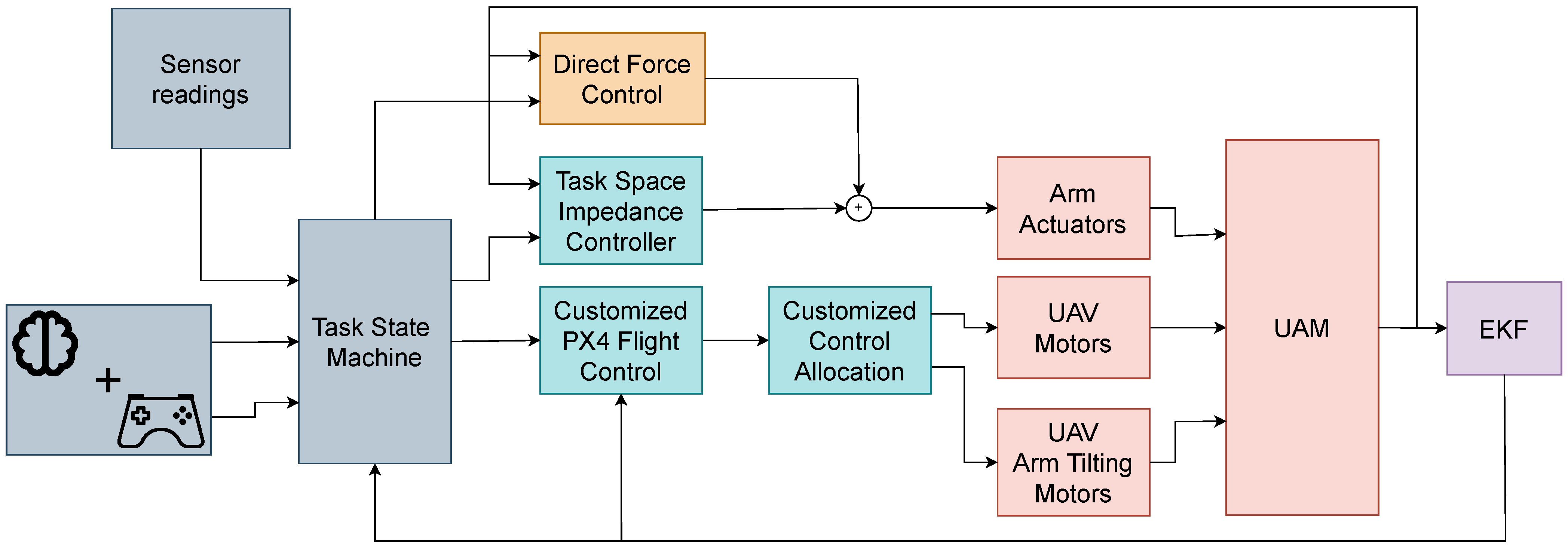
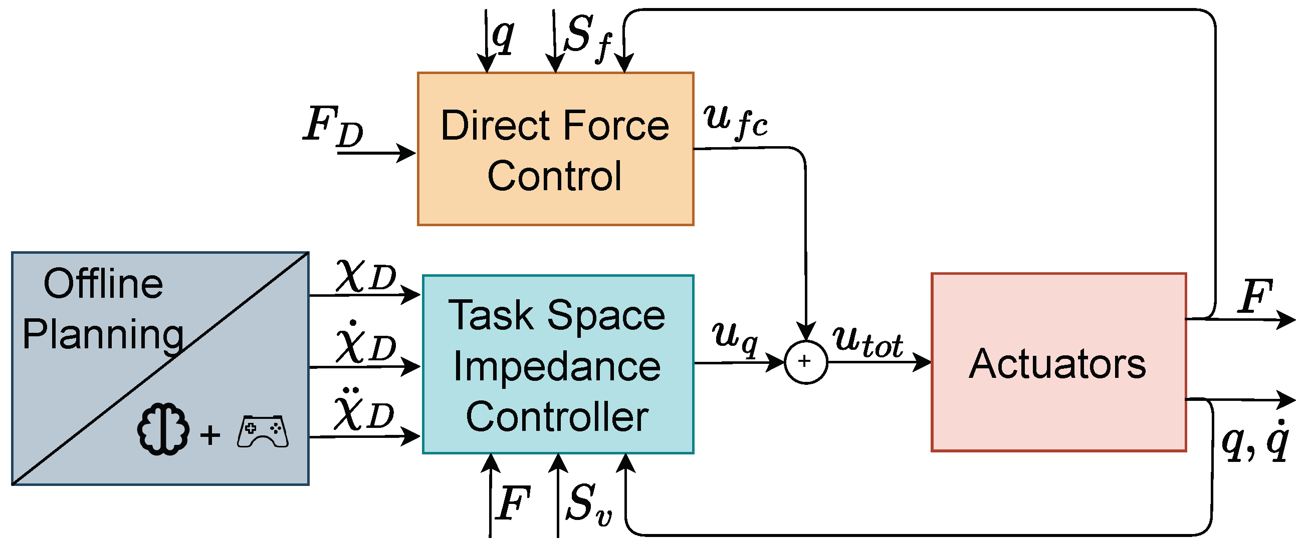
5.1. Controller Design

The PX4 flight controller (originally presented in [43]) stabilizes the platform and ensures position tracking for precise measurement patterns, while the arm controller provides safe interaction with the inspected environment with a parallel force–impedance control [44]:
  • In our customized PX4 firmware [17,35], both the controller and the relative allocation matrix have been changed with the one proposed in [40], allowing the control of both the motor velocities and tilt angles;
  • Concurrently, the E-E pose is controlled in the task space with an inverse Jacobian approach, ensuring the rejection of all external disturbances. A parallel impedance-force control is developed to ensure motion and force tracking simultaneously.
The manipulator control architecture is presented in Figure 8: the probe’s desired position, given by an operator or a measurement pattern, is filtered by an impedance control that uses the 6D force sensor feedback to achieve the desired compliancy on each direction while the probe is reaching a stable contact with the measured surface, preventing bumps to be propagated to the aerial platform. The parallel controller was already introduced in our previous work (see [5]). For clarity and reproducibility, we include its implementation below.
An impedance control law is responsible for handling the transition between contact-less ( F = 0 6 ) and contact-based motion ( F 0 6 ), correcting the Cartesian space references based on the force feedback. Once the contact is established, the system switches to a direct force control on the approach direction to give adequate pressure for the NDT equipment to operate while remaining compliant with the impedance control on the other directions. This selection is performed with the matrices
S v = 0 0 1 0 0 1 0 3 × 3 0 3 × 2 I 3 × 3 , S f = 1 0 0 0 3 × 1 .
where S v R 6 × n v , and S f R 6 × n f : n v and n f represent the dimension of the velocity-controlled and force-controlled sub-spaces in the same way as [44].
This matrix is used in a proportional–derivative (PD) control scheme to track the desired force, F D ( t ) R 6 , nullifying the error e F ( t ) = F ( t ) F D ( t ) R 6 :
u f c = J ( q ) ( I S v S v ) C S f K P f S f e F ( t ) + K D f λ ˙ d ( t ) ,
where C R 6 × 6 is the compliance matrix of the spring between the two elements in contact, K P f , K D f R n f × n f are positive definite gain matrices, and λ ˙ d = S f e ˙ F R is the time derivative of the force error weighted by the force-controlled sub-space matrix. The exponent ( · ) indicates the pseudo-inverse operator. The control scheme is completed by designing a Cartesian space impedance controller: taking into account the system dynamics, the joint torques are computed by choosing a properly virtual control input, q ¨ = u q R n . As stated in our previous work (see [5]), presenting our proof of concept, the position set-points are computed by double-integrating the auxiliary acceleration inputs u q . With x ˜ , x ˜ ˙ R 6 being the position and velocity errors, computed starting from the references and the actual feedback, it is then possible to impose
u q = J ( S v M a 1 ( M a S v x ¨ D + K D a S v x ˜ ˙ + K P a S v x ˜ S v F ) J ˙ ( q , q ˙ ) q ˙ ) ,
where M a , K D a , K P a R n v × n v represent the impedance mass, damping, and stiffness matrices, respectively; F = [ f e x t   m e x t ] T R 6 is the measured wrench, and the matrices S f and S v , again, divide the 6D space into commands addressing the motion control task and others addressing the force control task.
Measuring the interaction force indicated with F, the virtual control inputs can track the E-E references by computing the corresponding corrections, being compliant with the interaction surface. The complete parallel impedance–force control input is u t o t = u q + u f c .
The two control actions are decoupled via the orthogonal projection matrices S v and S f , which define complementary subspaces for velocity and force control, respectively, and satisfy the condition S v S f = 0 through construction. As a result, in accordance with [34], the overall control input is obtained as the sum of two independent components acting on orthogonal directions. Each controller thus preserves the stability properties and error dynamics derived in its respective subspace, as discussed in Appendix A. It is worth noting that, when the desired force is zero (i.e., λ = 0 ), the resulting controller reduces to a standard impedance controller acting only on the motion-controlled directions.

5.2. Shared-Control and Task State Machine

Shared control allows a human operator to supervise the system and intervene when needed, while the autonomous execution proceeds through a sequence of control modes. These modes are structured as a task-oriented state machine, which transitions based on the current state of the platform, as estimated by the onboard sensing system. The two ToF sensors compute the relative position of the target wall defining the mounting distance between the two sensors as d t o f , while d l ,   d r are the left and right ToF feedback; we use this information to compute the body frame wall front distance and orientation (yaw):
x w B = ( d r + d l ) / 2 ψ w B = arctan ( ( d r d l ) / d t o f )
Those quantities are filtered with a second-order Butterworth low-pass filter (LPF) to improve the quality measurement.
When the operator triggers the autonomous approaching control routine, the system keeps the relative wall distance to the desired value x w D B while annulling the relative yaw error. The control action is computed in B from the errors e x = x w D B x w B ,   e ψ = ψ w B as follows:
u B = K p , x e x K f f , x e ˙ x v R C y R C E N v R C z R C E N u = R B W u B u ψ = K p , ψ e ψ ,
where v R C ( · ) are the velocity input commanded through the RC, K p , x ,   K f f , x ,   K p , ψ are properly tuned gains, and R C E N is a binary variable (flag) that can be either 0 (disabled) or 1 (enabled) allowing the operator to manually control the UAM in the y B - z B plane, parallel to the work surface. In contrast, the control keeps the distance and orientation. Moreover, v D = u u ψ , p D = v D d t are the desired set-points for the flight controller stack. In this way, the operator can precisely guide the UAM to the desired measurement point.
The state machine handling the task execution is described in Figure 9; its evolution is commanded by a human operator entering the control loop via a standard RC. They can control the semi-autonomous operations acting on two commands to the standard RC while guiding the UAM in the scene sending set-points to the flight controller: EN_SHR_CTRL/DIS_SHR_CTRL to enable/disable the shared-control modality, and NEXT_MEAS to trigger the next measure routine.
After the operator drives the UAM to the inspection point, they trigger the shared-control operations, and the UAM starts to approach the work surface. The position controller (15) tracks an approaching trajectory, keeping constant a safety distance, d s , from the wall that is suitable for safely deploying the arm in position control mode. Once this initial control goal is satisfied, the operator can still move the UAM in the y B - z B plane, selecting the right inspection spot and then triggering the measurement procedure (NEXT_MEAS): R C E N is set to 0, keeping the current position in the y B - z B plane, and the impedance control mode is enabled. During the approaching routine, the system starts to pump coupling gel to the sensor until contact is established.
When a stable contact is detected, the system switches on the arm direct force control, raising the force set-point, F D , from the measured value to apply an F c o n t required for the UT sensor to retrieve the proper thickness measures. To then achieve smooth detachment from the work surface, the state machine decreases F D to 0 and switches again to the impedance control mode, while the wall position controller tracks an additional trajectory, bringing the UAM back to a d s from the wall.
The measure sequence is completed, and R C E N is set to 1, such that the user can repeat the inspection on a different spot, triggering the routine with an additional NEXT_MEAS command, or disable the shared control with DIS_SHR_CTRL to drive the UAM back to the landing site, turning off the wall position controller.

5.3. Safety Layers

Aerial inspections introduce various risks due to the disturbances arising during flight. In order to address them, a comprehensive safety layer was implemented to constrain the arm’s actuation, ensuring that the system operates within safe parameters. The specific limitations are as follows:
  • Position, velocity, and acceleration of the joints: constraints are applied to the movement of each joint to prevent unsafe or excessive motion.
  • Position, velocity, and acceleration in the operative space: limits are set on the overall motion of the arm within its working environment, avoiding trespassing in the field-of-view of other sensors, or near the propellers.
  • Effort, temperature, and power consumption of the actuators: monitoring and restricting these parameters helps prevent overheating, overexertion, and excessive power usage, possibly leading to system failure.
  • Forces and torques read via the tip sensor: these constraints ensure that the forces and torques exerted via and on the arm remain within safe limits, preventing damage to the arm.
The arm actuators are automatically stopped if any of the specified conditions are violated. The pilot can then either close the arm or restore it to its normal configuration.

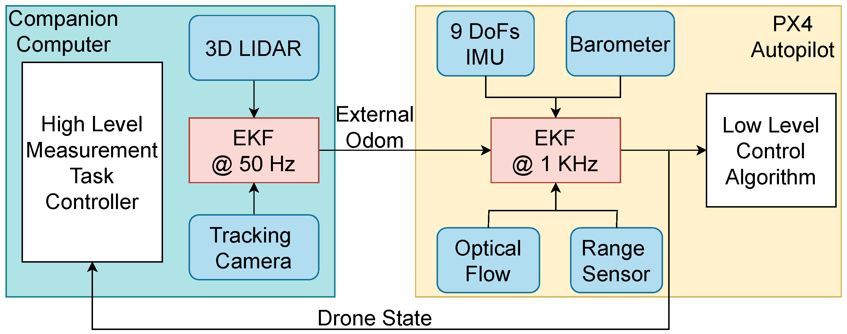
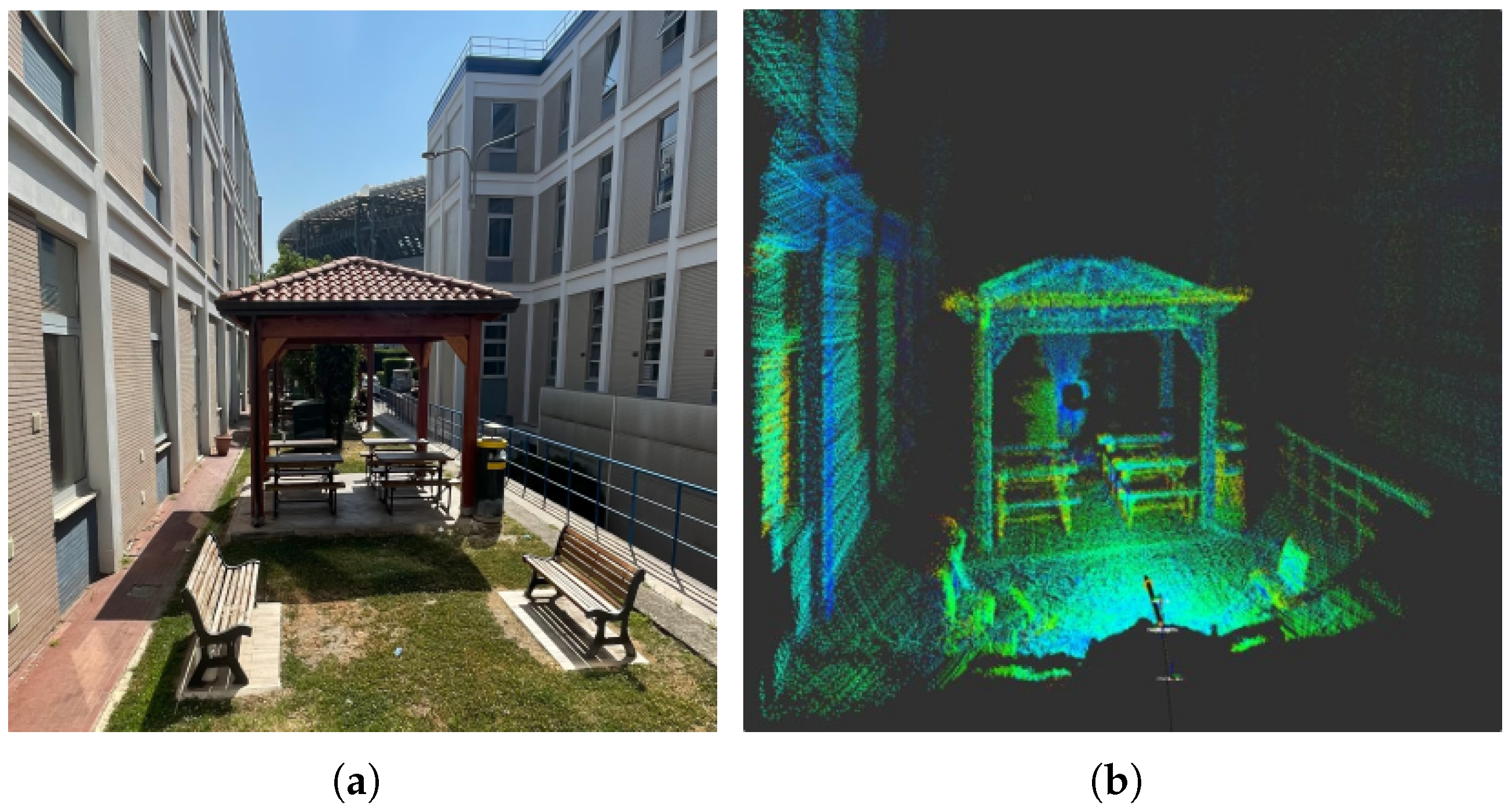
5.4. Localization and Navigation

The UAM’s navigation system is built to deliver precise localization and reliable performance in a variety of environments, employing multiple sensors with different technologies, orientations, and measurement ranges to ensure redundancy. The key components include the following:
  • Unilidar L1 PM (Unitree Robotics, Hangzhou, China): a 3D LIDAR sensor providing detailed point cloud data for accurate odometry and mapping.
  • Realsense T265 (Intel Corporation, Santa Clara, CA, USA): a tracking camera with an onboard IMU, offering position and velocity estimates through visual–inertial odometry.
  • ArkFlow (ARK Electronics, Salt Lake City, UT USA): an optical flow sensor measuring horizontal velocity and altitude by analyzing ground-facing data.
  • Pixhawk 6C (Holybro, Shenzhen, China) internal sensors, comprising the accelerometer, gyroscope, magnetometer, and barometer, support state estimation.
The UAV’s navigation and localization system (see Figure 10) operates on two levels: external odometry processed via a companion computer and internal position estimation managed via the Pixhawk flight controller. The companion computer fuses LIDAR data processed through an ICP algorithm and odometry from the Realsense T265 tracking camera. These are merged using an extended Kalman filter (EKF) to generate accurate odometry data, which is then sent to the Pixhawk controller. At the lower level, the Pixhawk uses its IMU, barometer, and Ark Flow sensor to estimate pose, velocity, and altitude. The internal Kalman filter fuses these internal sensors with external data to maintain accurate localization, even if some sensors fail. The adoption of EKF-based multi-sensor fusion remains a widely validated and reliable strategy in robotics, as also demonstrated in [45], where thermal, LiDAR, and GNSS data are combined to enable robust localization in harsh and GPS-degraded environments.
Additionally, the system allows for mapping and environment reconstruction using LIDAR point clouds and pose estimation, enabling the UAV to navigate and perform tasks in complex environments (an output example is provided in Figure 11). This comprehensive setup equips the UAV for autonomous flight, precise positioning, and reliable task execution across indoor and outdoor operational scenarios.

6. Results

Several experiments have been performed both in an indoor GPS-denied environment and an outdoor facility (see Figure 1), validating the effectiveness and robustness of the proposed system (video of the experiments: https://www.youtube.com/watch?v=R_ioYwADb9s (accessed on 16 July 2025)). The drone’s localization relies on the onboard sensor suite described in Section 5.4, employing SLAM-based algorithms to mitigate IMU drift over time and improve positional accuracy. The integration of front-facing ToF sensors enables reactive interaction with the environment, particularly in detecting and aligning with the work surface before contact. Concerning the described controller, the impedance gains used for the experiments are the same as those presented in [5].
The proposed system leverages rtabmap_ros for real-time 3D SLAM [46], generating a voxel-based octomap used both for global navigation and pose estimation. Compared to traditional 2D grid maps or raw point clouds, the octomap offers a memory-efficient and probabilistically consistent representation of the environment, supporting both obstacle-aware planning and surface-aware localization. This volumetric mapping approach allows the system to reconstruct the full 3D structure of industrial environments, enabling interaction with vertical or inclined surfaces that would be poorly represented in a 2D map.

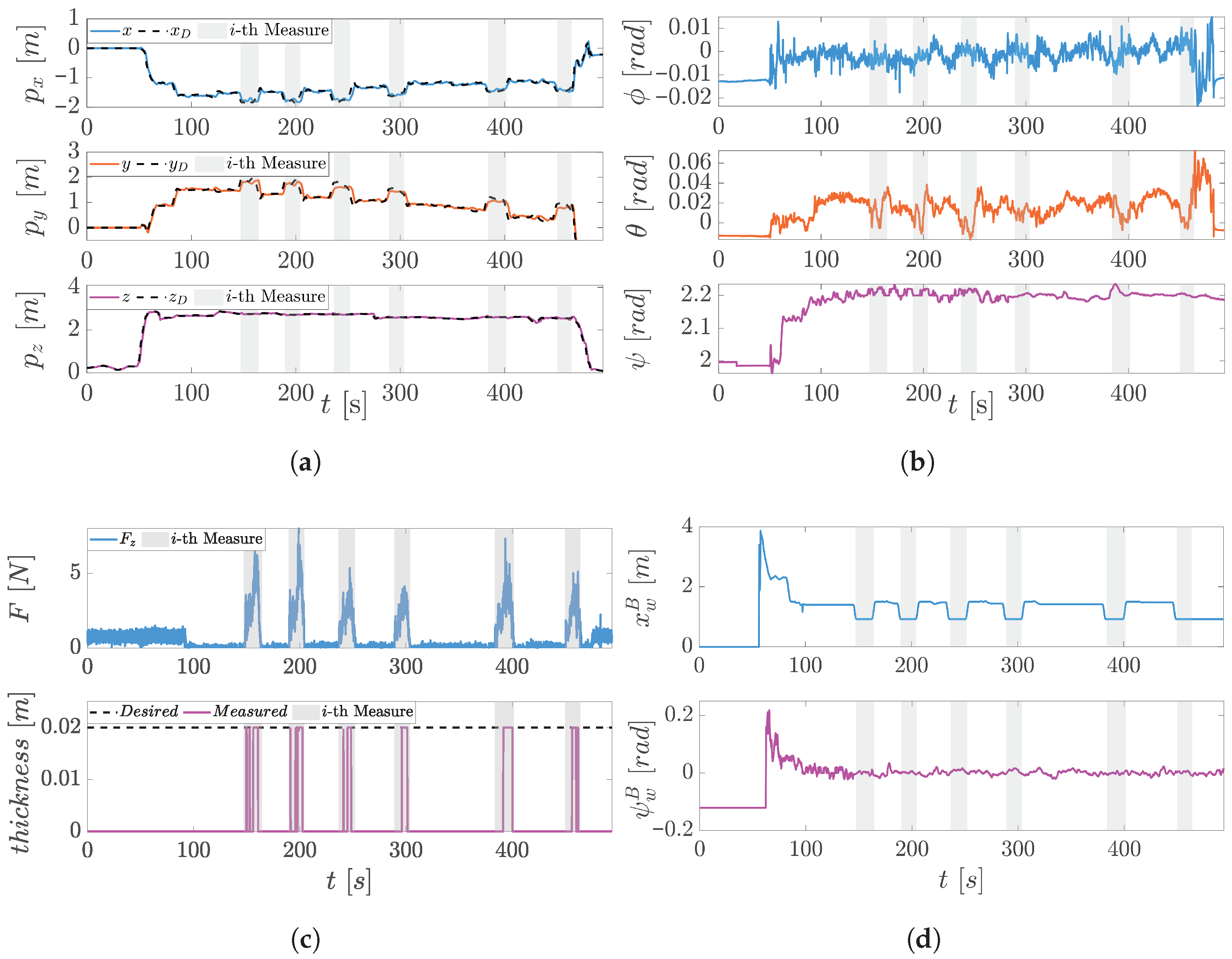
Inspection Task Execution

Indoor experiments were conducted at the University of Naples Federico II, within a facility specifically equipped to support the safe flight of non-standard aerial platforms. To ensure maximum safety during operations, the aerial system was secured with a safety tether, and experienced operators were present to supervise the tests and intervene promptly in case of anomalies. A safety pilot was always on standby, with the ability to override the autonomous behavior of the platform and trigger emergency landing procedures if necessary.
For the physical interaction task, a planar steel surface was selected as the contact target. This choice ensures reliable ultrasonic measurements, as the material and geometry are well characterized and compatible with the sensing instrumentation.
Outdoor experiments were carried out at the ENI Centro Olio facility in Trecate (Novara, Italy), where the system was deployed on multiple planar structures with varying surface curvatures. These tests aimed to evaluate the scalability, robustness, and repeatability of the proposed system in real-world industrial scenarios. As with the indoor trials, comprehensive safety protocols were followed to ensure correct execution and minimize risk during the operations.
In both cases, the task remains the same: A human operator is responsible for piloting the aerial platform within the inspection facility and guiding it toward the target surface. Once positioned, the operator sequentially triggers different control phases to enable a smooth and safe contact with the structure, as in Section 5.2. The system then performs the UT measurement without compromising the integrity of the surface. The task can be repeated or terminated based on the mission requirements. They control the UAV’s motion by sending velocity set-points through a standard RC interface. The inspection procedure follows a structured sequence consisting of three main phases: free flight, approach (governed by impedance control), and in-contact force control, during which the UT sensor acquires the required measurements. The transitions are handled through the task-level state machine, with operator supervision ensuring task safety and flexibility. This shared control architecture combines autonomy in physical interaction with human-in-the-loop adaptability, enabling responsive behavior in unstructured environments.
Before each measurement, the electric pump deposits a thin layer of viscous gel on the E-E tip to ensure proper acoustic coupling. To avoid transient sensor bias due to the application process, a recalibration is performed immediately after gel deposition. This enables reliable and repeatable force readings during contact.
The manipulator, composed of five position-controlled servo motors, adapts its configuration throughout the task. Concerning Figure 12a, the arm keeps a neutral “home” pose for the initial task phases (0–60 s); it transitions into the inspection configuration once the drone reaches a stable hover near the target (around 80 s). At this point, the control system actively minimizes the relative pose error between the E-E and the surface using SLAM (the environment reconstructed depicted in Figure 12b) and ToF feedback, establishing a suitable alignment for contact. The UAV’s pose is estimated via localization against the generated octomap, and this estimate is fused with IMU data and broadcasted to PX4 via a ROS interface, ensuring tight integration between perception and control. An example of the reconstructed map and real-time sensor readings is shown in Figure 12b, where the surface geometry and UAV trajectory during inspection are visualized.
The impedance control law then modulates the E-E’s position to achieve a compliant interaction during the successive interaction phases (the gray patches in Figure 12a), allowing stable surface contact while rejecting minor disturbances. The impedance controller continuously compensates for disturbances along the motion-controlled directions, preserving compliant behavior throughout the pushing phase. During this phase, it tracks a desired force profile composed of two ramps that reach a peak of 5 N. The corresponding interaction phases enable the acquisition of high-precision ultrasonic testing (UT) measurements, as illustrated in Figure 12a.
The platform tracking capability is highlighted in Figure 13a, depicting the outdoor experiments carried out in Novara. This extensive experiment showcases the repeatability and precision of the proposed system; six successive inspection processes are completed on the same spot by repeating different approaching/disapproaching routines. They highlight the UAV’s ability to accurately track position references derived from integrated RC velocity commands. The tilting propellers contribute significantly to maintaining a stable pose during interaction phases. Notably, the vehicle’s attitude (see Figure 13b) remains nearly constant during contact, indicating that the aerial platform successfully compensates for contact forces without significant reorientation. The only major attitude change is a deliberate yaw rotation used to align the drone with the surface normal prior to approach. The relative posture regulation is boosted by the ToFs reading, reconstructing the relative orientation and linear displacement setting as control goals to nullify them.
As shown in Figure 13c, the manipulator consistently achieved contact with minimal overshoot and maintained a stable interaction force. In particular, the F z force component that is aligned with the approaching axis closely follows the trapezoidal reference, confirming the impedance controller’s effectiveness in shaping the dynamic response. The UT sensor outputs highly consistent thickness measurements across repeated trials (≃0.019 m), further supporting the system’s precision and stability. These results are particularly relevant for real-world inspection scenarios, where repeatability is critical to ensuring reliability. Figure 13d shows how the ToF sensors continuously refine the UAV’s relative pose with respect to the surface, reducing variability during the approach phase and enabling consistent sensor positioning. In conclusion, Table 2 and Table 3 summarize the average timing for each phase of the inspection tasks, respectively, in the indoor and outdoor scenarios.
Overall, the results validate the proposed control and task execution framework, demonstrating not only the system’s capacity to perform precise, repeatable interactions but also its resilience to disturbances and variability in environmental conditions. The shared autonomy paradigm—coupling human supervision with autonomous, low-level control—proves effective in orchestrating complex physical tasks in challenging settings.

7. Conclusions

The research underscores the critical role of mechatronic integration in the successful fusion of a tilting multirotor drone and a robotic arm into a unified aerial manipulation platform. This integration is not merely mechanical but also involves a holistic approach that spans structural design, control architecture, and real-time communication, enabling the system to operate as a cohesive and responsive unit. By incorporating a shared control paradigm—where human oversight complements autonomous behavior—the platform achieves a balanced interaction between manual intuition and robotic precision. This hybrid control strategy significantly enhances both operational safety and task effectiveness, particularly in hazardous or hard-to-reach industrial environments where fully manual or fully autonomous systems may fall short.
The proposed system offers a comprehensive and practical solution to aerial non-destructive testing (NDT), with the robotic arm playing a key role in extending the platform’s manipulation capabilities. The implementation of parallel force–impedance control enables stable and adaptive physical interaction with complex surfaces, which is critical for the effective use of contact-based NDT tools such as ultrasonic thickness sensors. This control strategy ensures not only consistent contact force but also the necessary compliance to cope with surface irregularities, thereby improving measurement accuracy and repeatability.
Furthermore, this research lays the groundwork for future developments aimed at expanding the platform’s interactive capabilities during physical contact with surfaces. Upcoming investigations will focus on novel interaction tools and strategies that enable controlled sliding (see [47]) along the surface while maintaining stable contact. This will allow the inspection of multiple points or areas continuously without the need to repeatedly disengage and re-establish contact. Such advancements are expected to improve inspection efficiency and data consistency, particularly in scenarios requiring extended surface coverage and precise manipulation.

Author Contributions

Software, S.D., A.D.C., M.M. and S.M.; methodology, investigation, and validation, S.D. and A.D.C.; data curation, S.D. and A.D.C.; formal analysis and writing, S.D.; review and editing, B.S. and V.L.; data visualization, S.D.; supervision, V.L. and B.S.; project administration, V.L.; resources and funding acquisition, V.L. and B.S. All authors have read and agreed to the published version of the manuscript.

Funding

The research leading to these results has been supported by the AI-DROW project, in the frame of the PRIN 2022 research program, grant number 2022BYSBYX, funded by the European Union Next-Generation EU, and BRIEF “Biorobotics Research and Innovation Engineering Facilities” project (Project identification code IR0000036), funded under the National Recovery and Resilience Plan (NRRP), Mission 4 Component 2 Investment 3.1 of the Italian Ministry of University and Research, funded by the European Union—NextGenerationEU.

Institutional Review Board Statement

Not applicable.

Informed Consent Statement

Not applicable.

Data Availability Statement

Data will be made available upon request.

DURC Statement

The current research is limited to the field of aerial robotics and human-in-the-loop manipulation, which is beneficial for industrial inspection, maintenance in hazardous environments, and infrastructure monitoring. It does not pose a threat to public health or national security. The authors acknowledge the dual-use potential of technologies involving autonomous navigation and force-controlled aerial manipulators, and they confirm that all necessary precautions have been taken to prevent potential misuse. As an ethical responsibility, the authors strictly adhere to relevant national and international laws about DURC. The authors advocate for responsible deployment, ethical considerations, regulatory compliance, and transparent reporting to mitigate misuse risks and foster beneficial outcomes.

Acknowledgments

The authors gratefully acknowledge Pasquale Campanile for his invaluable work on the platform’s electronic components, which was crucial to the success of this work.

Conflicts of Interest

Author Salvatore Marcellini, Michele Marolla were employed by the company Leonardo S.p.A.; Alessandro De Crescenzo was employed by the company Neabotics. The remaining authors declare that the research was conducted in the absence of any commercial or financial relationships that could be construed as a potential conflict of interest.

Appendix A. Stability Analysis of the Parallel Force–Impedance Controller

In this appendix, we provide a formal stability analysis of the proposed parallel force–impedance controller for the aerial manipulator. The control architecture is composed of two decoupled subsystems: (i) a Cartesian impedance controller acting on the position-controlled directions and (ii) a force controller acting on the force-controlled directions. The decomposition is performed via the selection matrices S v and S f , satisfying the orthogonality condition S v S f = 0 , as in [44].

Appendix A.1. Impedance Subsystem Stability

We first analyze the stability of the impedance control law introduced in Section 5, beginning with the free motion case and then including compliant contact dynamics.

Appendix A.1.1. Free Motion (No Contact)

The impedance controller regulates the error x ˜ ( t ) = x ( t ) x D ( t ) between the actual and desired end-effector pose in the Cartesian space. Under the assumption of negligible external disturbances (or constant forces), the dynamics of the impedance-controlled subsystem reduce to the following:
M a x ˜ ¨ + K D a x ˜ ˙ + K P a x ˜ = 0
where M a , K D a , and K P a are symmetric positive definite matrices defining the desired impedance behavior. The candidate Lyapunov function is as follows:
V 1 ( x ˜ , x ˜ ˙ ) = 1 2 x ˜ ˙ M a x ˜ ˙ + 1 2 x ˜ K P a x ˜
Differentiating along the trajectories and substituting the closed-loop system in (A1) yields the following:
V ˙ 1 = x ˜ ˙ K D a x ˜ ˙ 0
Hence, the system is stable for positive definite K D a .

Appendix A.1.2. Compliant Contact (Elastic Environment)

Prior to analyzing asymptotic stability, we consider the influence of external forces on the system dynamics. Let the environment exert a contact force modeled as follows:
F = K e ( x e x )
where x e is the rest position of the environment, and K e is its stiffness matrix. The impedance control law still governs the desired dynamics:
M a x ˜ ¨ + K D a x ˜ ˙ + K P a x ˜ = F
Substituting the force model yields the following:
M a x ¨ + K D a x ˙ + K P a ( x x D ) = K e ( x e x )
which can be rearranged as follows:
M a x ¨ + K D a x ˙ + ( K P a + K e ) x = K P a x D + K e x e
We define the equilibrium point:
x ¯ = ( K P a + K e ) 1 ( K P a x D + K e x e )
We now define the Lyapunov function candidate:
V 1 = 1 2 x ˙ M a x ˙ + 1 2 ( x x D ) K P a ( x x D ) + 1 2 ( x x e ) K e ( x x e )
which is positive definite and radially unbounded. We take the following derivative:
V ˙ 1 = x ˙ M a x ¨ + ( x x D ) K P a x ˙ + ( x x e ) K e x ˙
= x ˙ ( M a x ¨ + K P a ( x x D ) + K e ( x x e ) ) = x ˙ K D a x ˙ 0
We now apply LaSalle’s invariance principle. The largest invariant set contained in V ˙ 1 = 0 is defined by x ˙ = 0 . If x ˙ = 0 , then x ¨ = 0 also, and the equilibrium condition reads as follows:
K P a ( x x D ) + K e ( x x e ) = 0 x = x ¯
Hence, the only invariant point is ( x , x ˙ ) = ( x ¯ , 0 ) , and the system is asymptotically stable.

Appendix A.2. Force Subsystem Stability

The force controller tracks a desired interaction wrench, F D R 6 , using a proportional–derivative scheme in the force-controlled subspace defined by S f . Let the force tracking error be as follows:
e F ( t ) = F ( t ) F D ( t )
and we define the projected error λ ( t ) = S f e F ( t ) R n f . The force control law ensures convergence of this error through the following:
u f c K P f λ ( t ) K D f λ ˙ ( t )
To analyze stability, we consider the following Lyapunov candidate function:
V ( λ , λ ˙ ) = 1 2 λ K P f λ + 1 2 λ ˙ K D f λ ˙
This function is positive definite, radially unbounded, and continuously differentiable. Its time derivative along the system trajectories is as follows:
V ˙ = λ K P f λ ˙ + λ ˙ K D f λ ¨ = λ ˙ ( K P f λ + K D f λ ¨ )
From the error dynamics governed by the control law, we can write the following:
K D f λ ¨ + K P f λ + K D f λ ˙ = 0
Therefore, we substitute the following back:
V ˙ = λ ˙ [ K D f λ ˙ ] = λ ˙ K D f λ ˙ 0
Since K D f 0 , V ˙ 0 , and V ˙ = 0 only when λ ˙ = 0 . In this condition, the dynamics reduce to the following:
K P f λ = 0 λ = 0
Thus, the largest invariant set in which V ˙ = 0 is the singleton { ( λ , λ ˙ ) = ( 0 , 0 ) } . According to LaSalle’s invariance principle, the origin is globally asymptotically stable for the force tracking error λ ( t ) , ensuring the convergence of the contact force to its desired value in the controlled subspace.

Appendix A.3. Combined System Stability

The total control input is given by the sum of the two orthogonal components:
u tot = u q + u f c
Since the velocity and force subspaces are orthogonal by construction ( S v S f = 0 ), the energy functions of the two subsystems do not interfere with each other. A global Lyapunov function for the parallel controller can be written as follows:
V = V 1 + V 2
whose time derivative is as follows:
V ˙ = V ˙ 1 + V ˙ 2 0
Therefore, under the assumptions of negligible unmodeled coupling and perfect decoupling between subspaces (as in [34,44]), the complete controller ensures the asymptotic stability of both motion- and force-tracking tasks.

References

  1. Sun, R.; Zhao, B.; Wu, C.; Qin, X. Research on Inspection Method of Intelligent Factory Inspection Robot for Personnel Safety Protection. Appl. Sci. 2025, 15, 5750. [Google Scholar] [CrossRef]
  2. Nooralishahi, P.; Ibarra-Castanedo, C.; Deane, S.; López, F.; Pant, S.; Genest, M.; Avdelidis, N.P.; Maldague, X.P.V. Drone-Based Non-Destructive Inspection of Industrial Sites: A Review and Case Studies. Drones 2021, 5, 106. [Google Scholar] [CrossRef]
  3. Piccina, A.; Bertoni, M.; Michieletto, G. A Taxonomy on Contact-Aware Multi-Rotors for Interaction Tasks. In Proceedings of the 2025 International Conference on Unmanned Aircraft Systems (ICUAS), Charlotte, NC, USA, 14–17 May 2025; pp. 355–361. [Google Scholar]
  4. Shaqura, M.; Alzuhair, K.; Abdellatif, F.; Shamma, J.S. Human Supervised Multirotor UAV System Design for Inspection Applications. In Proceedings of the 2018 IEEE International Symposium on Safety, Security, and Rescue Robotics (SSRR), Philadelphia, PA, USA, 6–8 August 2018; pp. 1–6. [Google Scholar]
  5. Marcellini, S.; D’Angelo, S.; De Crescenzo, A.; Marolla, M.; Lippiello, V.; Siciliano, B. Development of a Semi-autonomous Framework for NDT Inspection with a Tilting Aerial Platform. In Proceedings of the Experimental Robotics, Chiang Mai, Thailand, 26–30 November 2023; Ang, M.H., Jr., Khatib, O., Eds.; Springer: Cham, Switzerland, 2024; pp. 353–363. [Google Scholar]
  6. Feng, J.; Shang, B.; Hoxha, E.; Hernández, C.; He, Y.; Wang, W.; Xiao, J. Robotic Inspection and Data Analytics to Localize and Visualize the Structural Defects of Concrete Infrastructure. IEEE Trans. Autom. Sci. Eng. 2025; early access. [Google Scholar] [CrossRef]
  7. Dertien, E.; Stramigioli, S.; Pulles, K. Development of an inspection robot for small diameter gas distribution mains. In Proceedings of the 2011 IEEE International Conference on Robotics and Automation, Shanghai, China, 9–13 May 2011; pp. 5044–5049. [Google Scholar]
  8. Ross, B.; Bares, J.; Fromme, C. A Semi-Autonomous Robot for Stripping Paint from Large Vessels. Int. Jour. Rob. Res. 2003, 22, 617–626. [Google Scholar] [CrossRef]
  9. Ollero, A.; Tognon, M.; Suarez, A.; Lee, D.; Franchi, A. Past, Present, and Future of Aerial Robotic Manipulators. IEEE Trans. Robot. 2022, 38, 626–645. [Google Scholar] [CrossRef]
  10. Praveen, A.; Ma, X.; Manoj, H.; Venkatesh, V.L.; Rastgaar, M.; Voyles, R.M. Inspection-on-the-fly using Hybrid Physical Interaction Control for Aerial Manipulators. In Proceedings of the 2020 IEEE/RSJ International Conference on Intelligent Robots and Systems (IROS), Las Vegas, NV, USA, 25–29 October 2020; pp. 1583–1588. [Google Scholar]
  11. Ryll, M.; Muscio, G.; Pierri, F.; Cataldi, E.; Antonelli, G.; Caccavale, F.; Bicego, D.; Franchi, A. 6D interaction control with aerial robots: The flying end-effector paradigm. Int. J. Robot. Res. 2019, 38, 1045–1062. [Google Scholar] [CrossRef]
  12. Tzoumanikas, D.; Graule, F.; Yan, Q.; Shah, D.; Popovic, M.; Leutenegger, S. Aerial Manipulation Using Hybrid Force and Position NMPC Applied to Aerial Writing. arXiv 2020, arXiv:2006.02116. [Google Scholar] [CrossRef]
  13. Rashad, R.; Bicego, D.; Jiao, R.; Sanchez-Escalonilla, S.; Stramigioli, S. Towards Vision-Based Impedance Control for the Contact Inspection of Unknown Generically-Shaped Surfaces with a Fully-Actuated UAV. In Proceedings of the 2020 IEEE/RSJ International Conference on Intelligent Robots and Systems (IROS), Las Vegas, NV, USA, 25–29 October 2020; pp. 1605–1612. [Google Scholar]
  14. Bodie, K.; Brunner, M.; Pantic, M.; Walser, S.; Pfndler, P.; Angst, U.; Siegwart, R.; Nieto, J. An Omnidirectional Aerial Manipulation Platform for Contact-Based Inspection. In Proceedings of the Robotics: Science and Systems XV, Freiburg im Breisgau, Germany, 22–26 June 2019; Robotics: Science and Systems Foundation: Los Angeles, CA, USA, 2019. RSS2019. [Google Scholar]
  15. Peric, L.; Brunner, M.; Bodie, K.; Tognon, M.; Siegwart, R. Direct Force and Pose NMPC with Multiple Interaction Modes for Aerial Push-and-Slide Operations. In Proceedings of the 2021 IEEE International Conference on Robotics and Automation (ICRA), Xi’an, China, 30 May–5 June 2021; pp. 131–137. [Google Scholar]
  16. Nava, G.; Sablé, Q.; Tognon, M.; Pucci, D.; Franchi, A. Direct Force Feedback Control and Online Multi-Task Optimization for Aerial Manipulators. IEEE Robot. Autom. Lett. 2020, 5, 331–338. [Google Scholar] [CrossRef]
  17. Marcellini, S.; Cacace, J.; Lippiello, V. A PX4 Integrated Framework for Modeling and Controlling Multicopters with Til table Rotors. In Proceedings of the 2023 International Conference on Unmanned Aircraft Systems (ICUAS), Warsaw, Poland, 6–9 June 2023; pp. 1089–1096. [Google Scholar]
  18. Bodie, K.; Brunner, M.; Pantic, M.; Walser, S.; Pfändler, P.; Angst, U.; Siegwart, R.; Nieto, J. Active Interaction Force Control for Contact-Based Inspection With a Fully Actuated Aerial Vehicle. IEEE Trans. Robot. 2021, 37, 709–722. [Google Scholar] [CrossRef]
  19. D’Angelo, S.; Corrado, A.; Ruggiero, F.; Cacace, J.; Lippiello, V. Stabilization and control on a pipe-rack of a wheeled mobile manipulator with a snake-like arm. Robot. Auton. Syst. 2024, 171, 104554. [Google Scholar] [CrossRef]
  20. Tognon, M.; Chávez, H.A.T.; Gasparin, E.; Sablé, Q.; Bicego, D.; Mallet, A.; Lany, M.; Santi, G.; Revaz, B.; Cortés, J.; et al. A Truly-Redundant Aerial Manipulator System With Application to Push-and-Slide Inspection in Industrial Plants. IEEE Robot. Autom. Lett. 2019, 4, 1846–1851. [Google Scholar] [CrossRef]
  21. Sumathy, V.; Ghose, D. Quadrotor-Based Aerial Manipulator Robotics. J. Indian Inst. Sci. 2024, 104, 669–690. [Google Scholar] [CrossRef]
  22. Rasheed, U.; Ordaz, C.; Xu, X.; Hu, Y.; Li, S.; Sutton, T.; Cai, J. Understanding the Impact of Teleoperation Technology on the Construction Industry: Adoption Dynamics, Workforce Perception, and the Role of Broader Workforce Participation. J. Constr. Eng. Manag. 2025, 151, 04025085. [Google Scholar] [CrossRef]
  23. Berx, N.; Decré, W.; De Schutter, J.; Pintelon, L. A harmonious synergy between robotic performance and well-being in human-robot collaboration: A vision and key recommendations. Annu. Rev. Control 2025, 59, 100984. [Google Scholar] [CrossRef]
  24. Yang, C.; Zhu, Y.; Chen, Y. A Review of Human–Machine Cooperation in the Robotics Domain. IEEE Trans. Hum.-Mach. Syst. 2022, 52, 12–25. [Google Scholar] [CrossRef]
  25. Franchi, A.; Secchi, C.; Son, H.I.; Bulthoff, H.H.; Giordano, P.R. Bilateral Teleoperation of Groups of Mobile Robots with Time-Varying Topology. IEEE Trans. Robot. 2012, 28, 1019–1033. [Google Scholar] [CrossRef]
  26. Lee, D.; Franchi, A.; Son, H.I.; Ha, C.; Bülthoff, H.H.; Giordano, P.R. Semiautonomous Haptic Teleoperation Control Architecture of Multiple Unmanned Aerial Vehicles. IEEE/ASME Trans. Mechatron. 2013, 18, 1334–1345. [Google Scholar] [CrossRef]
  27. Young, M.; Miller, C.; Bi, Y.; Chen, W.; Argall, B.D. Formalized Task Characterization for Human-Robot Autonomy Allocation. In Proceedings of the 2019 International Conference on Robotics and Automation (ICRA), Montreal, QC, Canada, 20–24 May 2019; pp. 6044–6050. [Google Scholar]
  28. Selvaggio, M.; Cacace, J.; Pacchierotti, C.; Ruggiero, F.; Giordano, P.R. A Shared-Control Teleoperation Architecture for Nonprehensile Object Transportation. IEEE Trans. Robot. 2022, 38, 569–583. [Google Scholar] [CrossRef]
  29. Gioioso, G.; Mohammadi, M.; Franchi, A.; Prattichizzo, D. A force-based bilateral teleoperation framework for aerial robots in contact with the environment. In Proceedings of the 2015 IEEE International Conference on Robotics and Automation (ICRA), Seattle, WA, USA, 26–30 May 2015; pp. 318–324. [Google Scholar]
  30. Allenspach, M.; Lawrance, N.; Tognon, M.; Siegwart, R. Towards 6DoF Bilateral Teleoperation of an Omnidirectional Aerial Vehicle for Aerial Physical Interaction. In Proceedings of the 2022 International Conference on Robotics and Automation (ICRA), Philadelphia, PA, USA, 23–27 May 2022; pp. 9302–9308. [Google Scholar]
  31. Coelho, A.; Sarkisov, Y.; Wu, X.; Mishra, H.; Singh, H.; Dietrich, A.; Franchi, A.; Kondak, K.; Ott, C. Whole-Body Teleoperation and Shared Control of Redundant Robots with Applications to Aerial Manipulation. J. Intell. Robot. Syst. 2021, 102, 14. [Google Scholar] [CrossRef]
  32. Ruggiero, F.; Lippiello, V.; Ollero, A. Aerial Manipulation: A Literature Review. IEEE Robot. Autom. Lett. 2018, 3, 1957–1964. [Google Scholar] [CrossRef]
  33. Barakou, S.C.; Tzafestas, C.S.; Valavanis, K.P. Control Strategies for Real-Time Aerial Manipulation With Multi-Dof Arms: A Survey. In Proceedings of the 2025 International Conference on Unmanned Aircraft Systems (ICUAS), Charlotte, NC, USA, 14–17 May 2025; pp. 139–146. [Google Scholar]
  34. Lynch, K.M.; Park, F.C. Modern Robotics: Mechanics, Planning and Control; Cambridge University Press: Cambridge, UK, 2017. [Google Scholar]
  35. D’Angelo, S.; Pagano, F.; Longobardi, F.; Ruggiero, F.; Lippiello, V. Efficient Development of Model-Based Controllers in PX4 Firmware: A Template-Based Customization Approach. In Proceedings of the 2024 International Conference on Unmanned Aircraft Systems (ICUAS), Chania, Greece, 4–7 June 2024; pp. 1155–1162. [Google Scholar]
  36. eCalc. eCalc—Reliable Electric Drive Simulations. 2025. Available online: https://www.ecalc.ch/ (accessed on 26 June 2025).
  37. Zorić, F.; Suarez, A.; Vasiljević, G.; Orsag, M.; Kovačić, Z.; Ollero, A. Performance Comparison of Teleoperation Interfaces for Ultra-Lightweight Anthropomorphic Arms. In Proceedings of the 2023 IEEE/RSJ International Conference on Intelligent Robots and Systems (IROS), Detroit, MI, USA, 1–5 October 2023; pp. 7026–7033. [Google Scholar]
  38. Hui, T.; Fumagalli, M. Advancing Manipulation Capabilities of a UAV Featuring Dynamic Center-of-Mass Displacement. In Proceedings of the 2025 International Conference on Unmanned Aircraft Systems (ICUAS), Charlotte, NC, USA, 14–17 May 2025; pp. 347–354. [Google Scholar]
  39. Kotarski, D.; Kasać, J. Generalized Control Allocation Scheme for Multirotor Type of UAVs. In Drones; Dekoulis, G., Ed.; IntechOpen: Rijeka, Croatia, 2018; Chapter 4. [Google Scholar]
  40. Kamel, M.; Verling, S.; Elkhatib, O.; Sprecher, C.; Wulkop, P.; Taylor, Z.; Siegwart, R.; Gilitschenski, I. The Voliro Omniorientational Hexacopter: An Agile and Maneuverable Tiltable-Rotor Aerial Vehicle. IEEE Robot. Autom. Mag. 2018, 25, 34–44. [Google Scholar] [CrossRef]
  41. Allenspach, M.; Bodie, K.; Brunner, M.; Rinsoz, L.; Taylor, Z.; Kamel, M.; Siegwart, R.; Nieto, J. Design and optimal control of a tiltrotor micro-aerial vehicle for efficient omnidirectional flight. Int. J. Robot. Res. 2020, 39, 1305–1325. [Google Scholar] [CrossRef]
  42. Sadien, E.; Roos, C.; Birouche, A.; Carton, M.; Grimault, C.; Romana, L.E.; Basset, M. A detailed comparison of control allocation techniques on a realistic on-ground aircraft benchmark. In Proceedings of the American Control Conference 2019, Philadelphia, PA, USA, 10–12 July 2019. [Google Scholar]
  43. Meier, L.; Honegger, D.; Pollefeys, M. PX4: A node-based multithreaded open source robotics framework for deeply embedded platforms. In Proceedings of the 2015 IEEE International Conference on Robotics and Automation (ICRA), Seattle, WA, USA, 26–30 May 2015; pp. 6235–6240. [Google Scholar]
  44. Siciliano, B.; Sciavicco, L.; Villani, L.; Oriolo, G. Robotics: Modelling, Planning and Control; Springer: Berlin/Heidelberg, Germany, 2009. [Google Scholar]
  45. Schichler, L.; Festl, K.; Solmaz, S. Robust Multi-Sensor Fusion for Localization in Hazardous Environments Using Thermal, LiDAR, and GNSS Data. Sensors 2025, 25, 2032. [Google Scholar] [CrossRef] [PubMed]
  46. Labbé, M.; Michaud, F. RTAB-Map as an open-source lidar and visual simultaneous localization and mapping library for large-scale and long-term online operation. J. Field Robot. 2019, 36, 416–446. [Google Scholar] [CrossRef]
  47. D’Angelo, S.; Selvaggio, M.; Lippiello, V.; Ruggiero, F. Semi-autonomous unmanned aerial manipulator teleoperation for push-and-slide inspection using parallel force/vision control. Robot. Auton. Syst. 2025, 186, 104912. [Google Scholar] [CrossRef]
Figure 1. The UAM performing an outdoor NDT inspection.
Drones 09 00516 g001
Figure 3. Control architecture: a task-oriented state machine orchestrates the whole control framework, switching between different control modalities, depending on the current operational phase. Human intervention and feedback reconstruction play a crucial role in piloting states’ transitions.
Drones 09 00516 g003
Figure 4. Operative range (different quantities are presented; please refer to the legends to distinguish between ranges unit measures) (a) and motor characteristics at full gas (b) computed in eCalc [36]: the gray patch indicates the velocity at maximum range.
Drones 09 00516 g004
Figure 5. (a) NDT tool schematics. (b) Custom PCB.
Drones 09 00516 g005
Figure 6. (a) The proposed co-axial tilting octa-rotor equipped with a robotic arm. The fixed and body frames ( W ,   B ) are depicted. Each co-axial rotors groups define a frame, R i , while F e e is the E-E frame. (b) Omnidirectional drone schematic.
Drones 09 00516 g006
Figure 7. The 5 DoFs manipulator kinematic structure with a moving battery carriage. The main frames are depicted.
Drones 09 00516 g007
Figure 8. Aerial manipulator control architecture: detailed close-up view from Figure 3.
Drones 09 00516 g008
Figure 9. Task state machine scheme.
Drones 09 00516 g009
Figure 10. Localization system overview.
Drones 09 00516 g010
Figure 11. Outdoor environment reconstruction: (a) RGB camera images and (b) UAV sensors reconstruction.
Drones 09 00516 g011
Figure 12. Indoor tests: (a) the joint variables’ evolution shows compliance during the two interactions (gray patches) according to the force/torque feedback. The relative UT measures are depicted. (b) 3D representation of the environment reconstructed using RTAB-Map projected into an OctoMap.
Drones 09 00516 g012
Figure 13. In-contact inspection results: (a) UAV’s linear reference (dashed lines) and feedback (continuous lines). The compliant behavior minimizes the effect of external disturbances during the interaction on the UAV’s attitude (roll-pitch-yaw) (b). (c) Interaction force feedback and the UT sensor measures during the completed inspection in the successive interaction phases (gray patches). The force reference value is a trapezoidal wave culminating at F D = 5 N. (d) Work surface/drone relative position x w B and orientation ψ w B .
Drones 09 00516 g013
Table 1. Denavit–Hartenberg parameters for the robotic arm.
i a i (m) α i (rad) d i (m) θ i (rad)
10 π / 2 0 θ 1
2 a 2 00 θ 2
30 π / 2 0 θ 3
40 π / 2 d 4 θ 4
50 π / 2 0 θ 5
Table 2. Indoor experiment—task timing.
Task PhaseTiming [s]
Free flight and alignment0–60
Arm deploy60–80
Approach80–180
I Pushing180–200
II Pushing240–260
Retreat and landing260–300
Table 3. Outdoor experiment—task timing.
Task PhaseTiming [s]
Free flight and alignment0–100
Arm deploy100–120
Approach120–150
I Pushing150–170
II Pushing195–215
III Pushing245–265
IV Pushing219–315
V Pushing390–410
VI Pushing450–470
Retreat and landing470–500
Disclaimer/Publisher’s Note: The statements, opinions and data contained in all publications are solely those of the individual author(s) and contributor(s) and not of MDPI and/or the editor(s). MDPI and/or the editor(s) disclaim responsibility for any injury to people or property resulting from any ideas, methods, instructions or products referred to in the content.

