1. Introduction
Direction-of-arrival (DOA) estimation is a fundamental problem in array signal processing with wide-ranging applications in wireless communications, radar, sonar, and related fields. In recent years, with the rapid development and widespread application of unmanned aerial vehicles (UAVs), DOA estimation based on UAV arrays has attracted increasing attention due to its broad coverage and flexible configuration capabilities [
1,
2,
3]. The primary objectives of DOA estimation are to achieve high estimation accuracy and maximize the degrees of freedom (DOFs), defined as the upper bound on the number of sources that can be resolved simultaneously. Both of these performance metrics, however, are inherently limited by the size of the array aperture. For an M-element uniform linear array (ULA), when the multiple signal classification (MUSIC) method is used for DOA estimation, the spatial spectrum resolution capability is proportional to the fourth power of the aperture, and the DOFs are also constrained to
, meaning that at most
sources can be estimated.
To enhance estimation accuracy and expand the DOFs, sparse arrays with non-uniformly spaced sensor elements have received growing attention [
4]. These arrays leverage the concept of the difference co-array to synthesize a larger virtual aperture from a limited number of physical sensors. For a well-designed
M-element sparse array, the achievable DOFs can reach up to
[
5,
6,
7,
8,
9,
10,
11,
12,
13,
14]. This improvement is primarily driven by the enhanced spatial diversity provided by the difference co-arrays of sparsely distributed array elements, effectively extending the virtual aperture. The evolution of sparse array design can be traced back to minimum redundancy array (MRA) [
6], which maximizes the cardinality of virtual elements given a fixed number of physical sensors. Distinct from the MRA design rules, the minimum hole array (MHA) aims to ensure that the corresponding differential array minimizes the number of redundancies with uniform linear difference co-arrays [
7]. However, neither MRA nor MHA has specific expressions and structures. This limitation has led to extensive recent research on nested array (NA) [
10], coprime array (CA) [
6], and their generalized forms [
11,
12,
13,
14], which have specific expressions and structures.
Similar to the virtual array element construction in coprime arrays, ref. [
15] synthesizes a virtual coprime array by utilizing a ULA that receives coprime-frequency signals from the target. The virtual array aperture is further expanded through difference co-array processing based on this virtual coprime array structure. The key mechanism behind these enhancements lies in leveraging frequency-domain information to amplify the aperture expansion effect of sparse formations. Within the group-sparsity framework [
16,
17], subsequent studies [
18,
19,
20,
21] extended the concept of coprime-frequency ULA aperture expansion to multi-frequency ULAs. In [
22], DOA estimation algorithms were developed within the group-sparsity framework, effectively integrating cross-lags and self-lag information to enhance the performance of multi-frequency sparse arrays. Here, cross-lags information refers to the set of difference in co-arrays derived from the associated subarrays at two different frequencies. In contrast, self-lags information represents the difference in co-array structure obtained from the subarray at a single frequency. Furthermore, by incorporating array interpolation techniques [
22,
23], effectively addressed the hole-filling problem, namely, the reconstruction of missing or non-consecutive elements in the difference co-array within the multi-frequency difference co-array, thereby enabling the construction of a hole-free virtual ULA with an extended aperture.
As research in sparse array design advances, achieving higher DOFs through structural optimization alone has become increasingly challenging. To address these limitations, ref. [
24] introduced the concept of sparse array motion synchronization, enabling the synthesis of virtual arrays with expanded apertures and increased consecutive virtual elements. This approach significantly enhances both DOFs and DOA estimation accuracy by leveraging time-domain fusion of multiple signal snapshots to facilitate aperture expansion. Building on the motion-synthesized virtual array mechanism for hole filling, refs. [
25,
26,
27] proposed algorithms to optimize motion distances and corresponding array configurations, further extending the virtual aperture. To maximize the hole-filling benefits of array motion, researchers have introduced dilated array configurations [
28,
29]. These configurations can enhance degrees of freedom (DOFs) by up to threefold compared to the original sparse arrays while maintaining hole-free virtual arrays. Furthermore, advanced moving non-uniform sampling schemes have been proposed for arbitrary array structures. These schemes enable the realization of maximum hole-free continuous virtual arrays with minimal motion requirements [
30,
31,
32,
33].
Existing aperture synthesis algorithms primarily leverage one or two types of information, such as motion synthesis and multi-frequency synthesis in sparse arrays. However, to the best of our knowledge, no prior research has explored aperture synthesis that simultaneously integrates time, frequency, and spatial information to enhance DOA estimation accuracy and increase the DOFs in sparse arrays. The major contributions of the paper are as follows in detail.
We propose an aperture synthesis model that integrates time-frequency-spatial information for the uniform sparse array scenario of coprime-frequency motion. A closed-form expression for the synthesized virtual array element distribution is derived.
We design a coprime-frequency UAV array suitable for the synthesis model, with key parameters including the sparse uniform array structure, motion distance, and coprime-frequency parameters. Additionally, the virtual array distribution of proposed coprime-frequency UAV array under the proposed aperture synthesis model is provided.
The group-sparsity DOA estimation method suitable for the proposed aperture expansion model and the joint group-sparsity and virtual array interpolation DOA estimation method tailored for the proposed motion sparse uniform array are designed separately.
Simulation results demonstrate that, compared to existing sparse array aperture synthesis methods, the proposed coprime-frequency UAV array achieves the maximum number of continuous virtual elements and the minimum holes in the difference co-array. This is achieved given the same number of physical elements under the proposed aperture synthesis model. Moreover, both of the proposed DOA estimation methods yield significant improvements in estimation accuracy and in the number of identifiable sources.
2. Problem Formulation
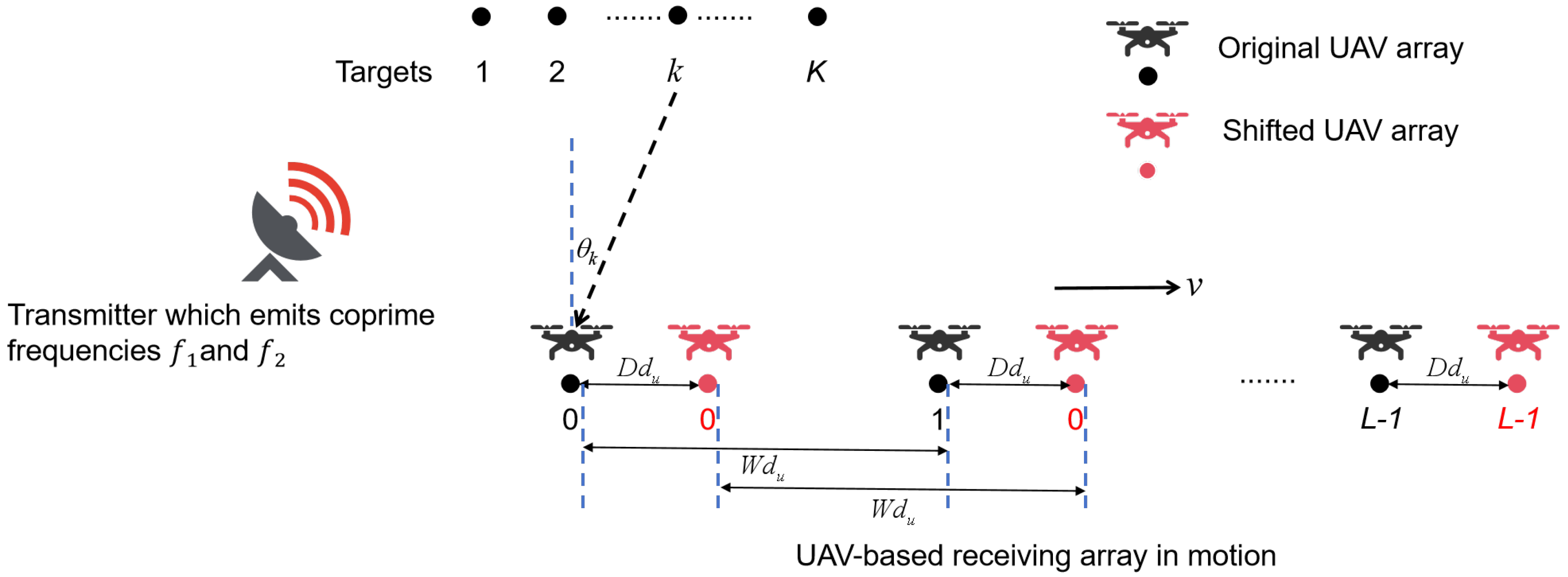
As shown in
Figure 1, consider
L moving UAVs equipped with a single antenna array element and receiving chains and inter-aircraft synchronization devices as the receiving end in the target detection scenario. In this target detection scenario, a pair of coprime continuous wave signals with carrier frequencies
and
(
) are simultaneously emitted by a single transmit sensor. The coprime carrier frequencies relationship can be described as follows:
where
M and
N are coprime positive integers (
). In this paper, we assume that the UAV arrays have a ULA structure with an element spacing of
, where
W is a positive integer,
c is wave velocity, and
is reference element spacing. For clarity and brevity, we refer to the array incorporating motion and coprime frequencies source scenes as the coprime frequency UAV array (CF-UAVA).
As the CF-UAVA moves, it receives reflected signals from
K far-field targets, with arrival angles denoted as
. Since the motion distance of the CF-UAVA is negligible compared to the distance from the targets to the receiving array, the arrival angles of the reflected signals at the receiving array can be considered constant [
34]. The CF-UAVA performs two samplings during its motion at a constant velocity
v. Each sampling consists of multiple snapshots, and the time interval between the two samplings is
Q. The motion distance of the CF-UAVA between the two samplings is given by
.
Define the signal received at frequency
during the
l-th sampling as
. The received signal for frequency
during the first sampling can be expressed as
where
represents the complex reflection coefficient of the
k-th target at frequency
. This coefficient is independently distributed across different frequencies and array elements. During each short sampling interval, the channel state remains constant, allowing the reflection coefficient to be treated as independent of time. The frequency after considering the Doppler shift is
.
denotes the additive white Gaussian noise at frequency
in the first sampling. Furthermore, the steering vector corresponding to
at frequency
is expressed as
Therefore, (
2) can be expressed in matrix form as follows:
where,
,
,
.
By comparing with (
4), we can derive the output of the receive array in the second sampling at frequency
as
where
It is assumed that the two samplings fall within the same coherent processing interval (CPI) [
21]. Due to the characteristic of narrow-band signal, the time delay can be compensated through a corresponding phase shift, which is expressed as
Thus, the array response matrix for the second sampling after phase shift compensation can be described in matrix form as
where,
,
.
By combining Equations (
5) and (
9), the following expression can be obtained:
where,
,
,
.
Similarly, the jointly processed received signal at
after phase shift compensation can be expressed as:
where
The definitions of the symbols and intermediate steps follow the same rules as those for frequency . No further elaboration will be provided.
3. Synthetic Array Fusing Array Motions and Coprime Frequencies
For the array response matrix of a single frequency described by either (
10) or (
11), the aperture extension stems from the hole-filling effect induced by half-wavelength motion, which enables up to three times the original virtual aperture. However, we aim to further leverage the information across different frequencies to extend the array aperture, thereby achieving higher DOFs and more precise DOA estimation. In this section, we propose an array synthesis framework that integrates array motion with coprime-frequency characteristics.
The virtual array configuration before and after motion at frequencies
and
is shown in
Figure 2. The sets of array locations (in units of
) of the original virtual array and the motion synthetic virtual array at frequency
corresponding to (
4) and (
10) can be respectively expressed as
It is worth noting that, to ensure all array positions are integers, both W and D must be integer multiples of N.
Similarly, the sets of locations of the original virtual array and the motion synthetic virtual array at frequency
can be respectively expressed as
Because of the unknown phase difference between and , the difference co-array of different frequencies cannot be directly applied to DOA estimation. For the convenience of analysis, we define the difference co-array between signals of the same frequency as the self-lags and that between signals of different frequencies as the cross-lags.
3.1. Synthetic Array Using Self-Lags
The covariance matrix of the received signal
after motion synthesis at the frequency
can be expressed as
where
is the power of the reflected signal of the
k-th target at the frequency
, and
is the noise power at the frequency
. By vectorizing
, we can obtain
where
, ⊗ denotes the Kronecker product,
Hence, we can reformulate (
20) as
where
The set of difference co-array locations, namely, self-lags at the frequency
are obtained as:
where
is the difference co-array of
.
Similarly, the vectorization of the covariance matrix at frequency
can be expressed as follows.
where
where
is the power of the reflected signal of the
k-th target at the frequency
, and
is the noise power at the frequency
. The self-lags at the frequency
are obtained as:
where
is the difference co-array of
.
3.2. Synthetic Array Using Both Self- and Cross-Lags
The cross-covariance matrix of
and
as follows.
where
is defined as the complex noise power of the
k-th source at frequencies
and
. By vectorizing
, we can obtain
where
Therefore, the set of difference co-array locations, namely, cross-lags at the frequency
and
are obtained as:
where
is the difference co-array of
and
,
It is noted that,
does not have a symmetric structure with respect to the zero position because of the coprime property of frequencies. Therefore, the conjugate position of
also needs to be provided. Similarly, by vectorizing the cross-covariance matrix
of
and
, we can obtain the vectorized covariance matrix and the corresponding virtual array distribution as
where
. The naming convention for variables and the calculation method are the same as in (
26) and thus will not be repeated here.
By combining Equations (
20), (
26), (
32) and (
39), the set of effective virtual array elements after the motion synthesis of coprime frequencies can be finally expressed as.
To better understand the effect of synthetic aperture under the proposed synthesis model, assume that the CF-UAVA’s configuration, coprime frequencies, and motion parameters are denoted by
. The distribution of its non-negative lags is shown in
Figure 3. CF-UAVA with 5 elements, after one motion synthesis utilizing coprime frequencies, the number of continuous lags reached 129, and the number of unique lags reached 149. Compared to single array motion synthesis or coprime frequency synthesis alone, this combined approach significantly enhances performance, laying a solid foundation for more accurate DOA estimation.
4. DOA Estimation Based Group-Sparsity
In this section, we propose a novel DOA estimation method that effectively addresses the issue where the cross-lags and self-lags in the designed synthetic virtual array cannot be directly applied to DOA estimation.
For the array manifolds described by (
20), (
26), (
32), and (
39), a direct joint subspace-based solution would require the signal power vectors
,
,
and
across all frequencies to be identical. However, due to the differences in complex reflection coefficients across frequencies, this assumption is generally not satisfied, which limits the applicability of conventional subspace methods. It is worth noting, however, that the spatial distributions captured by these four array manifolds are consistent and all satisfy the spatial sparsity constraint. Therefore, a group sparse recovery approach can be employed to mitigate the effects of phase discrepancies among different manifolds and facilitate the DOA estimation. In this work, we adopt the group Lasso framework to jointly model the four array manifolds and achieve sparse reconstruction of the target angular information. By combining the four covariance vectors (
20), (
26), (
32) and (
39), a new array response equation can be derived as
where
where
represents a
zero matrix.
The angular distributions of the
K targets corresponding to the four column vectors of
are consistent. Therefore, the DOA estimation after coprime-frequency motion synthesis can be treated as a group-sparsity problem aimed at locating non-zero entries within the angular search space [
23]. In this paper, the group-sparsity method is employed to solve the problem [
35]. (
42) can be sparsely represented as follows:
where
is the dictionary matrix of
,
G denotes the size of search grid, and
represents the signal spatial distribution vector under grid search, where
denotes the spatial distribution vector corresponding to the array response in (
22), and the other three terms are defined accordingly.
,
,
represents all-one column vector,
represents a
zero matrix,
.
It is noted that in the first
rows of
, each set of G rows represents the angular distribution of the sources under different combinations of frequencies and sampling instances, respectively. Since different combinations share the same angular distributions of the sources, (
47) can be transformed into the optimization problem:
where
,
denotes
-norm of
,
is the allowable error bound.
Finally, (
48) can be equivalently expressed as the following convex optimization problem:
where
is a penalty parameter. By solving the aforementioned optimization problem, the spatial spectrum estimation result can be expressed as
.
5. Proposed CF-UAVA
To effectively improve the utilization of virtual elements in the aperture extension model that integrates time-frequency-spatial information, reduce redundancy among virtual elements, and further enhance the degrees of freedom (DOF) and DOA estimation performance of the synthesized array. We propose a novel CF-UAVA structure, which is designed by integrating coprime frequencies, motion distances, and array configurations to achieve superior aperture extension performance under the proposed aperture synthesis method. Under the assumption of ULA, the array configuration parameters of CF-UAVA satisfy the following relationships:
Therefore,
, the effective virtual array element set in (
41) can be simplified as:
Since
is a set symmetric about position 0, when
, most elements of
are located in the negative region, while most elements of
are in the positive region.
mainly consists of four parts:
,
shifted left by
D,
shifted right by
, and
shifted left by
. Therefore, the maximum element position of
is given by
Correspondingly, the maximum element position of
is given by
It is easy to see from (
52) and (
53) that
holds true, indicating that the maximum extent of
is determined by
. After appropriately designing the CF-UAVA’s array parameters, frequency parameters, and motion distance, it becomes straightforward to ensure that the non-negative portions of
,
, and
are entirely contained within a continuous virtual array segment of
, i.e.
where
denotes the longest continuous lags within the unique lags set.
Under the proposed synthesis framework, the maximum hole-free array synthesis for CF-UAVA can be equivalently formulated as
Therefore, from the perspective of maximizing the number of continuous lags, this paper proposes a high-performance CF-UAVA configuration applicable to the proposed time-frequency-spatial aperture synthesis framework.The parameters of proposed CF-UAVA as follows
The distribution of contiguous lags after synthesizing the aforementioned CF-UAVA structure is as follows:
The number of contiguous lags and unique lags reaches
and
, respectively. The distribution of the non-contiguous virtual array segments after synthesis is
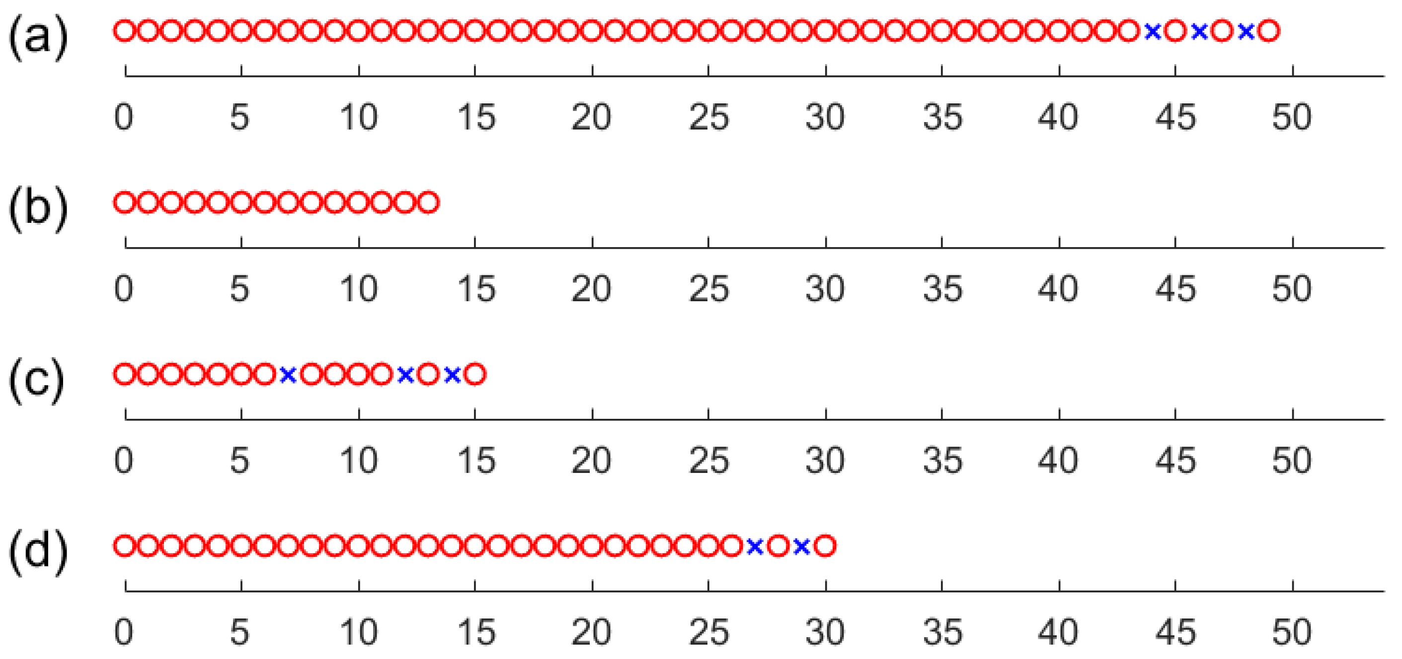
We take a specific example to intuitively illustrate the synthesis performance of the proposed CF-UAVA configuration in
Figure 4. The CF-UAVA parameters are set to
. In this case, the number of continuous lags reaches 87, and the number of unique lags reaches 93. In comparison, for the dilated nested array (3-DNA,
) with maximum motion synthesis efficiency [
29], the maximum number of contiguous and unique lags after a single half-wave length movement (
) is 27 and 25, respectively. Meanwhile, for the coprime frequencies uniform array (
), the equivalent numbers of contiguous and effective virtual array elements are 13 and 25, respectively. Furthermore, to further validate the superiority of the proposed CF-UAVA configuration under the array synthesis strategy, we also evaluate the synthesized array element distribution using other array parameters
, for which the numbers of contiguous and effective lags are 53 and 57, respectively.
6. DOA Estimation Based Group-Sparsity with Array Interpolation for CF-UAVA
This section proposes a higher precision DOA estimation method applicable to the proposed CF-UAVA. Firstly, redundant components in the group sparsity-based reconstruction method are eliminated, thereby reducing the search dimensionality of the optimization problem in (
49). Subsequently, to further enhance the utilization of virtual elements, virtual array interpolation techniques are employed to improve the DOA estimation method within the group sparsity synthesis framework introduced in
Section 4. Specifically, this approach fills the holes in the synthesized virtual array, enabling the construction of a larger covariance matrix with Hermitian-Toeplitz structure and a corresponding extended virtual ULA, ultimately achieving improved DOFs and higher-resolution DOA estimation.
Based on the CF-UAVA array configuration parameters proposed in (
57), we can obtain
Therefore, the first two virtual array element sets on the right-hand side of (
51) are fully covered. Accordingly, among the four equations jointly considered in (
42), (
20) and (
26) can be completely covered by (
32) and (
39), leading to a new array response that retains only the cross-lags, given as follows:
where,
,
,
.
The variable definitions in the sparse representation of the array response (
47) and the sparse optimization problem (
49) need to be adjusted accordingly, and the specific details will not be elaborated here.
To address the issue of holes in the virtual array domain, we choose to perform Toeplitz reconstruction of the covariance matrix based on the atomic norm minimization [
19]. Define the distribution of the virtual ULA to be interpolated as follows:
where
is the number of interpolated ULA. The reconstructed array manifold matrix can be expressed as
where
.
The array response matrices at
and
are reconstructed with respect to
to be interpolated. Zero-padding is applied at the positions corresponding to holes’ locations, resulting in the updated array response matrices given by
The positional relationship between
and
,
are represented using two binary column vectors, given as follows:
The covariance matrix to be completed can be expressed as
where, ∘ represents Hadamard product,
,
,
denotes the redundancy averaging matrix, and its elements are defined as
is a small positive constant introduced to ensure the denominator remains non-zero.
When the number of targets is less than the number of virtual array elements after interpolation, the matrix recovery problem of
can be reformulated as a low-rank structured matrix completion problem [ref].
where
,
denotes a Hermitian Toeplitz matrix constructed using
as its first column, and
is a parameter related to the received noise. This NP-hard rank minimization problem mentioned can be reformulated into a solvable convex optimization problem by leveraging the atomic norm minimization.
where
is regularization parameter.
Since the reconstructed covariance matrix
shares the same spatial spectral information with
and
, it is necessary to incorporate a spatial sparsity constraint associated with
in (
61). The resulting sparse reconstruction problem can be formulated as
where,
denotes all one vector of dimension , shares the same spatial spectral information with , denotes the mixed noise power.
By combining (
70) and (
61), the new group sparse optimization problem can be derived as follows:
where,
,
.
Here, we use the method of Lagrange multipliers to combine (
69) with (
74), resulting in the following composite optimization problem:
This convex optimization problem can be solved using the CVX toolbox. Finally, the spatial spectrum estimation results can be obtained by performing eigenvalue decomposition on the completed covariance matrix .
7. Simulation Results
In this section, we conduct numerical simulations to validate the superior performance of the proposed array synthesis strategy and DOA estimation methods. Under the condition of equal numbers of physical arrays, we compare the DOF and DOA estimation among three aperture synthesis approaches: (1) the proposed time-frequency-spatial array synthesis method, marked as TFSS; (2) the frequency-spatial array synthesis method integrated sparse array with coprime frequency [
15], marked as FSS; and (3) the time-spatial array synthesis method integrated moving sparse array [
24], marked as TSS. The configuration parameters, including array geometry, frequencies, and motion distance for the three synthesis methods, are illustrated in
Figure 4. All reflected signals impinging on the receiving array are assumed to have the same SNR, and the noise is modeled as additive white Gaussian noise. The amplitudes of the complex fading coefficients across different frequencies are identical, while the phase differences follow a uniform distribution over the interval
. The spatial search grid for DOA estimation is set to
. For synthetic array after TSS, which does not involve frequency synthesis, we employ a Lasso-based compressive sensing approach [
36]. For synthetic array after FSS, we adopt the DOA estimation method proposed in [
15], specifically designed for coprime frequencies. For synthetic array after TFSS, both the proposed group-Lasso method and the proposed group-Lasso with virtual array interpolation approach tailored for the proposed CF-UAVA are applied, marked as GL and GLI in order. The regularization parameters for all optimization problems are set to
. The performance of DOA estimation is characterized by the root mean square error (RMSE) of angle estimation, defined as follows:
where
Q denotes the number of Monte Carlo trials, and
and
represent the true direction and the estimated direction of the
k-th source in the
q-th trial, respectively.
7.1. The Number of DOFs
In the experiments, the source distributions under the different array configurations are identical, with sources uniformly distributed over the range
. The number of sources is set to 10, 15, and 25, respectively. The number of snapshots is fixed at 500, and the signal-to-noise ratio (SNR) is set to 10 dB. The experimental results are shown in
Figure 5.
As shown in
Figure 5, when the number of targets is 10, all array synthesis methods are capable of identifying all targets. However, due to the phase differences between frequencies, spurious peaks and less sharp spectral peaks appear in the spatial spectrum of the coprime frequencies synthesis array. In contrast, the proposed time-frequency-spatial array synthesis method (TFSS) achieves clear resolution under both the GL and GLI estimators. When the number of targets increases to 15, neither the coprime frequencies synthesis (FSS) nor the motion synthesis method (TSS) can accurately resolve all sources, as this number exceeds their number of unique lags. On the other hand, the proposed CF-UAVA maintains distinct resolution and sharp spectral peaks even with 15 and 25 sources, demonstrating the superiority of the proposed array synthesis strategy in terms of DOF.
7.2. The Performance of DOA Estimation Accuracy
Next, we evaluate the RMSE performance versus SNR for the proposed synthetic array (TFSS) by using the two DOA estimation methods (GL and GLI) introduced in this paper. The performance is compared with other aperture synthesis approaches (TSS and FSS). In the simulations, the number of targets is set to 8 uniformly distributed within the interval of
. The search grid is set to
. A total of 200 Monte Carlo trials are conducted, and the number of snapshots is fixed at 500.
Figure 6 illustrates the RMSE performance of DOA estimation versus SNR under the three array synthesis strategies.
It can be observed that, due to the increased number of unique virtual array elements after synthesis, the proposed CF-UAVA configuration outperforms both the FSS and TSS synthetic arrays under the same number of physical sensors across both DOA estimation methods. Moreover, the GLI method achieves better estimation accuracy than the proposed GL method, as it reconstructs a broader range of virtual continuous lags.
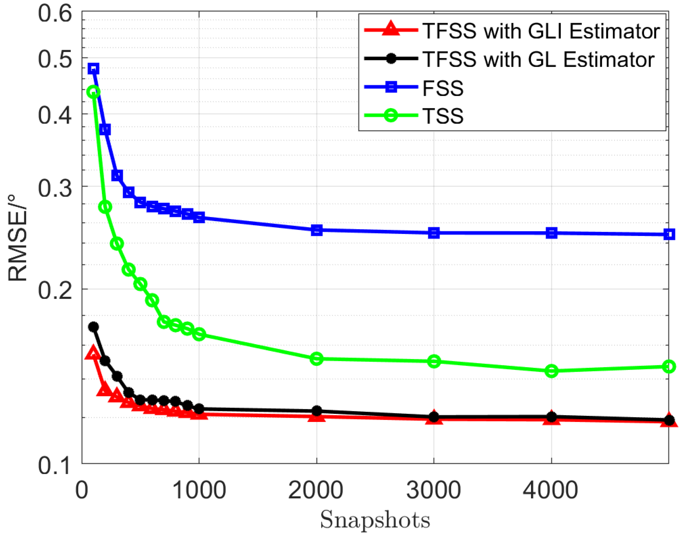
Finally, the variation of RMSE versus the number of snapshots is simulated. The SNR is fixed at 10 dB, the number of snapshots ranges from 100 to 5000, implementing a variable step size (100 for 100∼1000 snapshots, 1000 for 2000∼5000 snapshots). The other simulation parameters are consistent with Subection 7.2.
Figure 7 shows the RMSE performance of DOA estimation versus the number of snapshots under the three array synthesis strategies.
As shown in
Figure 7, the proposed TFSS method achieves better estimation accuracy than the other two synthesis strategies, TSS and FSS, across GLI and GL estimators. Moreover, the performance gain is more pronounced in the small snapshots regime, which demonstrates the effectiveness of the proposed methods in scenarios with limited snapshots.
8. Conclusions
This paper proposes an innovative sparse array synthesis method based on the UAV array, which effectively integrates coprime frequency information and array motion. The proposed approach significantly enhances the virtual array aperture. We derive the distribution of virtual array elements, providing a theoretical foundation for further optimization of UAV array design. Based on the proposed synthesis framework, the CF-UAVA is designed by jointly optimizing the coprime frequencies, motion distance, and the UAV array structure. As a result, the number of continuous difference co-arrays and unique co-arrays after CF-UAVA synthesis reaches and , respectively. Furthermore, a DOA estimation algorithm under the group sparsity framework is developed for the general case of the proposed array synthesis method, and another DOA estimation algorithm incorporating virtual array interpolation within the group sparsity framework is proposed tailored for the CF-UAVA configuration. Both DOA estimation methods utilize the enlarged virtual aperture after synthesis to achieve improved estimation accuracy. Finally, numerical simulations demonstrate that the proposed methods outperform existing array synthesis approaches in several key performance metrics. (1) DOFs: The proposed array synthesis method based on CF-UAVA achieves a higher number of resolvable sources due to its extended virtual aperture. (2) DOA Estimation Accuracy: the proposed DOA estimation methods outperform existing array synthesis approaches in DOA estimation accuracy. For example, at an SNR of 5 dB, the RMSE of the proposed method is approximately 47% lower than that of TSS and 83% lower than that of FSS. (3) Robustness to Limited Snapshots: even with limited data snapshots (e.g., 50–100), the proposed method maintains high estimation accuracy, whereas traditional methods suffer from performance degradation. These results highlight the effectiveness of the proposed method in advancing high-resolution DOA estimation for UAV arrays.
Looking ahead, we plan to further validate and enhance the proposed framework from the following two perspectives:
Error calibration research:
In practical implementations, motion-induced position errors are inevitable during the synthesis of a movable UAV array. To ensure reliable performance evaluation and robust estimation, we are investigating effective error calibration techniques to compensate for such inaccuracies. These methods will serve as a critical foundation for real-world deployment and will be reported in future publications.
Preliminary experimental verification:
Toward physical validation, a rail-guided linear array system has been designed to simulate the movement of UAVs along a single axis. This setup effectively reduces off-axis motion errors and provides a controlled environment for preliminary testing. The further refinement is currently underway. The experimental findings, together with the developed error compensation strategies, will be presented in a follow-up study.


