Article

Surface Change and Stability Analysis in Open-Pit Mines Using UAV Photogrammetric Data and Geospatial Analysis

by
Abdurahman Yasin Yiğit
1 and
Halil İbrahim Şenol
2,*
1
Department of Geomatics Engineering, Faculty of Engineering, Mersin University, 33000 Mersin, Türkiye
2
Department of Geomatics Engineering, Faculty of Engineering, Harran University, 63100 Şanlıurfa, Türkiye
*
Author to whom correspondence should be addressed.
Drones 2025, 9(7), 472; https://doi.org/10.3390/drones9070472
Submission received: 2 June 2025 / Revised: 29 June 2025 / Accepted: 30 June 2025 / Published: 2 July 2025

Abstract

Significant morphological transformations resulting from open-pit mining activities always present major problems with site safety and slope stability. This study investigates an active marble quarry in Dinar, Türkiye by combining geospatial analysis and photogrammetry based on unmanned aerial vehicles (UAV). Acquired in 2024 and 2025, high-resolution images were combined with dense point clouds produced by Structure from Motion (SfM) methods. Iterative Closest Point (ICP) registration (RMSE = 2.09 cm) and Multiscale Model-to-Model Cloud Comparison (M3C2) analysis was used to quantify the surface changes. The study found a volumetric increase of 7744.04 m3 in the dump zones accompanied by an excavation loss of 8359.72 m3, so producing a net difference of almost 615.68 m3. Surface risk factors were evaluated holistically using a variety of morphometric criteria. These measures covered surface variation in several respects: their degree of homogeneity, presence of any unevenness or texture, verticality, planarity, and linearity. Surface variation > 0.20, roughness > 0.15, and verticality > 0.25 help one to identify zones of increased instability. Point cloud modeling derived from UAVs and GIS-based spatial analysis were integrated to show that morphological anomalies are spatially correlated with possible failure zones.

1. Introduction

Open-pit mines are dynamic workplaces where surface excavation operations are carried out for the extraction of natural resources. Such workplaces pose high risks in terms of occupational health and safety, including landslides, rock falls, heavy machinery, and the use of explosives [1,2]. Excavation and dumping activities in these areas affect not only production efficiency but also critical factors such as environmental impacts, occupational safety, site stability, and the local ecosystem. Therefore, timely and accurate monitoring of topographic changes is essential for operational planning and for maintaining safety standards [3,4].
Conducting frequent, high-precision surveys of entire mining sites using traditional land surveying methods is both costly and operationally challenging [5,6]. Decades of advancements in Unmanned Aerial Vehicle (UAV) assisted photogrammetry technologies, which have undergone rapid development and widespread dissemination in the last decade, have rendered the modeling of large areas at high resolution, with expediency and cost-effective feasibility [7,8]. The data obtained by photogrammetric methods are not limited to two-dimensional orthomosaic imagery; they can also be combined with detailed digital elevation models (DEMs), point clouds containing interpoint elevation information, and three-dimensional (3D) models derived from them [9,10]. However, it is also evident that this data, in and of itself, merely constitutes a visual or geometric representation; further spatial analysis methods are requisite to integrate it into decision making processes [11].
The analysis of open-pit mines through a geomorphological lens provides significant insights into the processes driving environmental change and supports the development of effective land reclamation strategies [12,13,14]. This type of monitoring necessitates the continuous evaluation of mine geometry, surface topography, and alterations associated with extraction activities [15,16]. Significant advancements in surveying technologies, encompassing ground-based, aerial, and satellite platforms, have enhanced the acquisition of topographic data over the past decade [17,18]. Noteworthy advancements in this regard include the utilization of terrestrial and airborne LiDAR, along with Structure from Motion (SfM) photogrammetry, which have been instrumental in facilitating this transformation [19,20]. Despite these advancements, limitations persist in achieving real-time or near-real-time monitoring. Conventional ground surveys remain labor-intensive and spatially constrained, while terrestrial laser scanning frequently encounters issues such as uneven point density and occlusion related data gaps [21,22,23]. Although high-resolution LiDAR mapping provides detailed elevation data, it involves substantial financial and logistical resources [24,25,26]. Furthermore, the spatial resolution of numerous contemporary active and passive remote sensing systems is inadequate for generating DEMs with the requisite accuracy for detailed geomorphological analyses [27,28].
In recent years, SfM has gained prominence as a cost-effective photogrammetric technique, particularly advantageous for research and applications with limited financial resources [29,30]. When integrated with UAVs, modern autopilot technologies, high-resolution digital cameras, and lightweight Global Positioning System (GPS) systems, SfM enables the capture of ultra-high-resolution imagery with remarkable efficiency. These integrated advancements have made it possible to conduct frequent topographic surveys, facilitating the detection and analysis of geomorphic changes through morphological algorithms in a practical and economical manner [31,32]. Consequently, UAV-based assessments of landscape dynamics have been increasingly adopted in a variety of environmental settings within the scientific community [33,34,35].
In recent years, while UAVs and SfM technologies have found growing applications in geomorphological studies, their use in surface mining monitoring remains relatively underrepresented in the literature. Notable exceptions include studies by Panara et al. (2024) [36], Hasegawa et al. (2023) [37], Kim et al. (2022) [38], Trepekli et al. (2022) [39], Lee & Lee (2022) [40], and Meng et al. (2023) [41] who demonstrated the utility of UAVs in determining fracture orientations, estimating earthwork volumes, analyzing terrain morphology, and generating detailed 3D mine models through point cloud data. In a similar vein, Jia et al. (2022) [42] and Hao et al. (2023) [43] employed 3D models constructed from UAV and terrestrial laser scanning (TLS) data to assess slope stability using three-dimensional finite difference modeling. Similarly, Ajayi and Ajulo (2021) [44] employed UAV photogrammetry to monitor stockpile volumes and demonstrated its practicality for high-resolution surface modeling in mining operations.
A comprehensive review by Duarte et al. (2021) [45] systematically examines how digitalization processes in open-pit mining are structured under the “Mining 4.0” concept. The study details how tools such as UAV photogrammetry, terrestrial laser scanning, and Geographic Information Systems (GIS) are utilized for surface modeling and deformation monitoring. The study further emphasizes that digital photogrammetry offers high-precision, low-cost solutions for 3D model generation and volume calculation; it provides a more flexible and time-efficient data production framework compared to traditional methods. In this context, the integration of digital tools into open-pit marble quarry and the development of decision support systems are of strategic importance for both environmental monitoring and the optimization of production processes.
At this stage, GIS provides a complementary and empowering analysis framework for interpreting, classifying, comparing, and spatially interpreting large volumes of photogrammetrically acquired data [46,47,48]. GIS possesses both raster and vector analysis capabilities, enabling it to transform the numerical density of photogrammetric data into information that can be transferred into decision support processes. Consequently, the integration of photogrammetry and GIS has emerged as a novel monitoring paradigm, facilitating not only imaging but also advanced analyses such as morphological assessment, risk zoning, and change monitoring [49,50].
In areas susceptible to morphologically aggressive change, such as open mining sites, the utilization of photogrammetric surface models in conjunction with GIS establishes the foundation for numerous critical applications. These applications include excavation volume monitoring, the regulation of dumping areas, the identification of excessive slopes, the analysis of surface deformations, and even the predetermination of potential disaster risks such as landslides [5,51]. When the richness of point cloud data in terms of geometric and spatial content is supported by segmentation, roughness, verticality, and volumetric analyses to be performed on these data, both in-field intervention processes are accelerated and engineering decisions can be based on scientific foundations [52,53,54].
Similarly, Chand et al. (2024) [55] developed a monitoring approach that integrates UAV-based close-range photogrammetry with the Cloud-to-Cloud (C2C) algorithm in CloudCompare to address internal dump slope stability issues in large-scale open-pit coal mining projects in India. The study’s findings include the precise detection of both minor and major centimeter-scale displacements using time-series point clouds and validation of deformation zones through field observations and complementary stability assessments. This approach is characterized as a fast, cost-effective, and non-invasive method for deformation monitoring in extensive dump sites. Bamford et al. (2020) [56] conducted an applied study across open-pit mines on four continents. They used UAV-based photogrammetric point clouds to systematically analyze pre- and post-blast surface morphology changes, pre-split hole alignment, blast-induced muck pile volumes, blasted block size distribution, wall deformations, and bench face angle deviations. Utilizing CloudCompare, they conducted normal vector analysis and slope classification, facilitating visual comparisons between design and actual slope angles. Their findings revealed a direct correlation between angular deviations in pre-split holes and surface fracture intensity. This observation not only underscores the influence on final bench geometry but also lends credibility to the efficacy of UAV-based digital structural mapping in conducting both visual and parametric stability analyses. Similarly, Tucci et al. (2019) [57] validated UAV-derived volume measurements against terrestrial laser scanning data, reporting sub-centimetric accuracy in recyclable waste stockpile monitoring. They found that dense point cloud models derived from UAV images gave volume measurements with sub-centimetric accuracy. The conclusion drawn by the authors that UAV-derived DEMs are appropriate even in operational environments with limited access complements the method employed in this study, especially in dump zones defined by geometric complexity and dynamic topographic changes.
However, in the literature, there are very few holistic and GIS-supported applications of point cloud data with such detailed geometric analysis, especially for the evaluation of irregular and high-risk structures such as rubble piles. Bar and McQuillan (2021) [58] demonstrated how empirical stability classification systems can be complemented by morphometric segmentation to produce more spatially explicit risk maps. Additionally, Esposito et al. (2017) [59] analyzed volumetric excavation and active site changes in the Sa Pigada Bianca open-pit mine on Sardinia Island using multi-temporal UAV photogrammetry data. By applying the Multiscale Model-to-Model Cloud Comparison (M3C2) algorithm in CloudCompare to detect statistically significant changes between point clouds and processing the data in ArcGIS, they accurately calculated the extracted material volume at high spatial resolution, demonstrating the superior accuracy and interpretability of point cloud-based change analysis over traditional DEM differencing methods.
In addition, Xiang et al. (2018) [60] conducted DEM differencing analyses using multi-temporal high-resolution surface models derived from UAV imagery at the Miyun Iron Mine in China and employed the Slope Local Length of Autocorrelation method to distinguish regular anthropogenic surface patterns such as terrace structures. This approach enabled the simultaneous monitoring of both volumetric and morphometric surface changes, demonstrating the potential of UAV data to play an effective role in production process tracking and environmental planning. In a separate study, Padró et al. (2022) [61] conducted detailed volumetric and morphometric analyses of erosion-affected areas in open-pit mines in Catalonia, Spain, using surface models generated from drone imagery without the need for reference data. Using DEMs differencing and GIS-based slope classification, they were able to identify those areas with slopes exceeding 30° accounted for 49% of total erosion. This demonstrates that unmanned aerial system-based analyses can effectively support dynamic mine monitoring even in the absence of prior digital DEMs via morphological interpolation.
In general, volume changes are examined with simple raster analyses based on surface differences, while segmentation and morphological structure analyses are limited [62]. Consequently, the geometric potential inherent in photogrammetric data remains underutilized within the GIS framework. However, the time-series point clouds obtained with UAV data provide critical insights not only about change measurement but also about the geometric nature of the formed structure and its physical behavior in the field [63,64].
A systematic review was conducted by Tangadzani et al. (2024) [65], which revealed the growing use of UAV-based photogrammetry for monitoring slope deformations in open-pit mining. The findings, derived from 24 relevant publications, emphasize that photogrammetric surface models allow the tracking of both lateral and vertical slope movements when produced at regular temporal intervals. However, the study notes that most of the existing literature offers low temporal resolution, typically annual or semiannual, potentially missing sudden deformations. The study also underscores the paucity of methods for monitoring lateral displacements, the increasing reliance on RTK/PPK techniques over Ground Control Points (GCPs), and the ongoing need for enhanced accuracy and modeling capacity. While UAV photogrammetry has been demonstrated to exhibit clear advantages over traditional methods in terms of site safety, time efficiency, and spatial coverage, the authors underscore the persistent existence of significant methodological gaps, particularly in time-series deformation analysis.
Additionally, Liu et al. (2023) [66] integrated Monte Carlo simulation with the M3C2 algorithm to improve the statistical robustness of subsidence monitoring in coal mines, highlighting the adaptability of advanced change detection techniques in complex terrains. Özdaş et al. (2024) [67] further demonstrated that M3C2 provides more robust 3D displacement detection than classical DEM differencing, particularly in open-pit mining contexts. Furthermore, Cirillo et al. (2024) [68] demonstrated the broader applicability of UAV-derived point clouds by conducting a rockfall hazard assessment in coastal cliff environments, highlighting the versatility of such methods beyond open-pit mines.
In consideration of the methodological advancements and gaps in the extant literature, the objective of this study is to employ a comprehensive quantitative and spatial approach to elucidate the morphological changes in an open-pit marble quarry. To this end, a comparative analysis was conducted using point clouds and digital elevation models (DEMs) derived from multi-temporal UAV photogrammetry. Specifically, the topographic variations induced by excavation and dumping activities were examined through surface models from two distinct temporal periods, processed with CloudCompare software (version 2.12, open-source software developed by Daniel Girardeau-Montaut, Telecom ParisTech, Paris, France) [69]. Volume changes were calculated using the 2.5D volume calculation method, and dump and excavation zones were delineated through segmentation. Stability was further assessed by roughness and verticality metrics, identifying zones with high slopes and irregular surfaces as potential landslide risk areas.
Although comparisons of volume differences are common in the literature, the integration of segmentation-supported roughness and verticality analyses for irregular and hazardous zones such as dump piles is a highly innovative approach with limited precedents [70,71]. Furthermore, the use of open-source software like CloudCompare [69], which provides advanced point cloud analysis capabilities, enhances the accessibility and repeatability of such analyses [72,73]. These outputs provide an applied contribution to both mining engineering and remote sensing/GIS fields [74,75].
Despite these advancements, a comprehensive, multi-metric UAV-based framework specifically tailored for detailed morphological characterization and stability assessment of open-pit marble quarries remains underexplored. This study addresses this gap by integrating multi-temporal UAV photogrammetry with robust point cloud metrics—including M3C2 differencing, surface roughness, and verticality—and GIS-based spatial classification to deliver a replicable method for accurate surface change detection and proactive risk mapping. It is hypothesized that this integrated approach will enhance the precision and spatial resolution of conventional methods, which often rely on a single metric or are limited to two-dimensions, by allowing the spatial identification of surface zones exhibiting higher-than-average instability potential, as determined by metric thresholds derived from empirical observations of dumped and excavated areas.
The methodology developed in this study was implemented using repeatable open-source software, ensuring that the entire workflow can be replicated for analogous research contexts. Outputs obtained from CloudCompare (version 2.12) can be easily integrated into other GIS platforms for extended spatial analysis and reuse. Thus, the combined use of UAV-derived point clouds, DEMs, M3C2 differencing, and surface metrics such as roughness and verticality demonstrates the efficacy of dynamic observation as a superior alternative to conventional static methods frequently employed in mining operations. This interpretation of surface models not only documents current conditions but also provides critical support for predicting potential hazards and planning on-site interventions on a scientific basis.

2. Materials and Methods
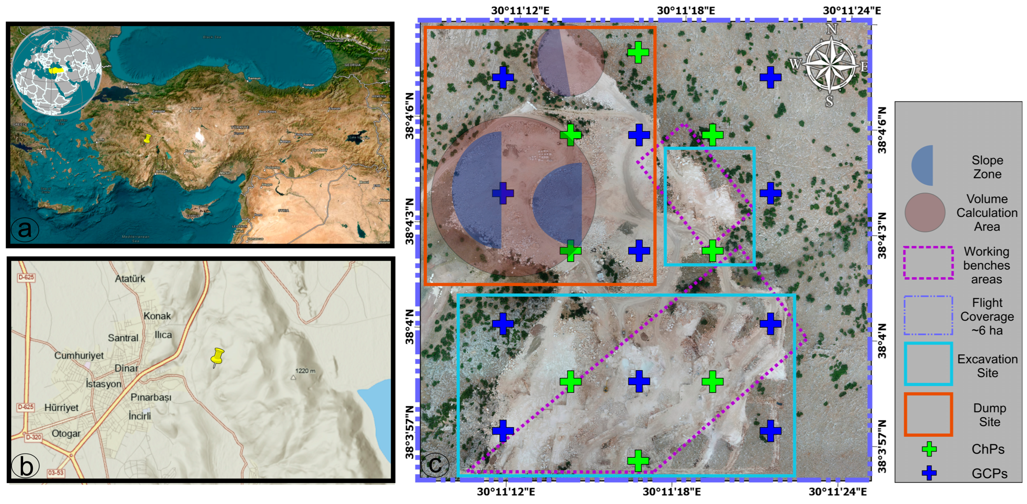
2.1. Study Area

The research was carried out at an open-pit marble quarry situated in the Dinar region of Afyonkarahisar Province, western Türkiye (Figure 1). The site is located in the Inner Western Anatolian region and is recognized for its abundant marble deposits, which are part of Türkiye’s extensive marble belt [76]. The site’s average elevation is 940 m above sea level; its longitude is 30.167° E and its latitude is 38.065° N.
The region’s semi-arid climate, characterized by scorching summers and cold, moist winters, exerts a significant influence on weathering processes and the operational challenges associated with open-pit mining. Regional lithology mostly consists of mesozoic carbonate rocks, particularly limestones and dolomitic formations, which have undergone tectonic deformation and metamorphism to generate high-quality marble deposits. These geological characteristics underline the significance of the region as a base for marble extraction and exportation in Türkiye [77].
The selected mining location exemplifies a stepwise bench mining technique, marked by substantial excavation and dumping operations that have progressively altered the surface topography. The ongoing extraction process has induced dynamic alterations in topography, particularly in excavation fronts, waste dump sites, and access ramps. The uneven geometry of mine surfaces and associated dangers, such as slope failure or deformation of waste rock dumps, provides an ideal site for UAV-based photogrammetric surveillance.

2.2. Data Collection and UAV Photogrammetry

This study uses a multi-temporal approach to monitor topographic changes in an open-pit marble quarry site using a UAV-based photogrammetric imaging system. The study looked at changes between two different years.
The DJI Phantom 4 PRO V2.0 (DJI, Shenzhen, China) model UAV was chosen for this photogrammetric use. This model is widely used due to its suitability for various terrain conditions and photogrammetric accuracy, as well as its high user control.
The DJI Phantom 4 Pro V2.0 remains a commonly used UAV for high-resolution photogrammetric surveys due to its proven accuracy, ease of deployment, and cost-effectiveness, particularly in small- to medium-scale projects [78,79,80]. It is acknowledged that more recent UAV models with advanced sensors are available; however, this model provides an adequate balance between operational simplicity and data quality for the purposes of this study. In addition, the selection of this platform was guided by its demonstrated capabilities, including its ability to maintain stable flight at lower altitudes than that achievable with fixed-wing systems, its capacity to capture high-resolution imagery through its integrated fixed camera, and its user-friendly interface [81]. Small and medium-sized areas would find it perfect in terms of its fast deployability, detail resolution, and economy of cost. Its fixed, high-quality camera system, autonomous flight support, and consistent data generating at low altitudes help to explain its popularity even more. Comprising the imaging system, the integrated camera is a top-notch digital sensor with a fixed focal length [82]. The camera’s dimensions are 13.2 mm in width, 8.8 mm in height, and 8.8 mm in focal length, with a total resolution of 5472 × 3648 pixels. Even on low-altitude flights, this system provides high detail separation; its 73.74° horizontal field of view and 53.13° vertical field of view help with effective imaging of large areas with fewer flight lines.
Map Pilot Pro (Drones Made Easy, San Diego, CA, USA) [83] was used throughout the flight planning process. By means of automatic altitude adjustment based on the elevation model of the terrain, the terrain awareness feature of the software guarantees constant Ground Sampling Distance (GSD) (Version 5.11.2) and so optimizing the flight. The software’s full compatibility with DJI platforms, the ability to test and edit flight routes in advance, and its automatic data collection capability were also cited as advantages.
The two imaging flights were conducted on 15 March 2024 and 15 March 2025, with the same field boundaries and parameters employed in previous iterations. Each UAV mission covered an area of approximately 6 hectares and collected 185 nadir images at an altitude of ~73 m. This configuration yielded a GSD of 2.0 cm. While the dump zones are visually analyzed in detail in Figure 2, the excavation boundaries and benches are clearly annotated in Figure 1c. The imaging was performed using a double grid flight pattern, which was planned with 80% forward overlap and 60% side overlap. This ensured both configuration accuracy and stereo matching. Although the total coverage area may appear limited given the flight parameters, the mission was specifically designed to focus on the actively evolving excavation and dumping zones. This deliberate spatial restriction allowed for dense, high-accuracy surface modeling and precise change detection within the most critical regions of the open-pit operation. Moreover, the integrity of the imagery was maintained due to clear, windless weather conditions, and both UAV missions were flown between 11:00 AM and 12:00 PM local time to minimize shadow effects and ensure uniform illumination, thereby improving photogrammetric accuracy. No issues such as ghosting or light flares were observed during image acquisition.
A total of eleven GCPs and eight Check Points (CPs) were placed in the field. The GCPs were utilized as geodetically defined control points for the photogrammetric processing of the images, while the CPs were employed as reference points for the independent assessment of product accuracy. All GCPs and Check Points were measured using a Topcon HiPer VR Global Navigation Satellite System (GNSS) receiver (Topcon Corp., Tokyo, Japan), which provides high-precision positioning with static mode accuracy of ±3 mm + 0.4 ppm (horizontal) and ±5 mm + 0.5 ppm (vertical). Identical GCP locations were used in both the 2024 and 2025 UAV campaigns to ensure spatial consistency across datasets. All coordinates were transformed into the national coordinate system using standardized projection parameters. These points were then integrated into the data processing process.
The images were processed using Agisoft Metashape Professional (v. 1.8.5) (Agisoft LLC, St. Petersburg, Russia) [84], following a Structure from Motion (SfM) workflow that reconstructs 3D scene geometry from overlapping images [85,86]. In the initial phase, distinctive key points were automatically detected and matched using scale and rotation-invariant algorithms such as the Scale-Invariant Feature Transform [87,88,89,90,91]. Image alignment, adaptive camera calibration, and bundle adjustment were performed with high-quality settings to optimize camera poses and minimize projection errors [92,93]. The resulting sparse point cloud was densified using Multi-View Stereo algorithms [92,93,94,95,96,97], followed by mild depth filtering, outlier removal, and point classification to enhance surface detail and accuracy. This procedure was executed with the quality parameter and the depth filtering parameter adjusted to high and mild settings, respectively. This configuration was selected to enhance the level of detail and to maintain a reasonable noise level.
Eleven GCPs and eight CPs, surveyed with a Topcon HiPer VR GNSS receiver, provided absolute georeferencing in WGS84-UTM Zone30. Both datasets (2024 and 2025) were acquired and processed using identical flight plans, hardware, image quality, and processing parameters to ensure temporal consistency. For more comprehensive algorithmic details, readers are referred to [85,86,87,88,91,95,97].

2.3. Accuracy Analysis and Workflow Overview

In this study, the spatial accuracy of DEM and orthomosaic products derived from photogrammetry, as well as the error metrics calculated over a total of eight CPs were evaluated in accordance with international standards. The study revealed the overall spatial accuracy levels of photogrammetric products.
For each CP, the Root Mean Square Error (RMSE) was calculated using Equation (1) based on the differences between the coordinates measured from the model and the actual coordinates measured by GNSS in the field. The R M S E x , R M S E y , and R M S E z values for component-based accuracy and the 3D RMSE value for combined accuracy were calculated with Equation (2).
R M S E x , y , z = 1 n i = 1 n ( x , z , y i x ^ i , y ^ i ,   z ^ i ) 2
R M S E 3 D = R M S E x 2 + R M S E y 2 + R M S E z 2
Moreover, a C2C distance study was performed to enable a comparison of the two time point cloud datasets. The exact registration of the two models in 3D space was made possible and surface variances were revealed in great part by this study. A first alignment between the two datasets was carried out before the C2C analysis was started.
Although both datasets were initially georeferenced using identical GCPs in the same reference system (WGS84-UTM Zone30), minor residual misalignments may occur due to block adjustment errors and GNSS measurement noise. Therefore, the Iterative Closest Point (ICP) algorithm was applied as an additional fine registration step to achieve sub-centimeter local alignment accuracy and minimize propagation of small residual errors in change detection. The fine registration was performed with a maximum of 100 iterations and a convergence threshold of 1 × 10 5 to ensure sub-centimeter alignment accuracy. This procedure does not alter the actual terrain variations but enhances the robustness of surface differences.
To achieve this, the ICP algorithm was employed to compute the optimal rotation and translation parameters and refine the geometric alignment between the model pairs [98,99], thereby maximizing the similarities between the two point clouds and ensuring reliable C2C distance calculations. The C2C method entails the identification of the closest point corresponding to each point in the first dataset (2024) within the second dataset (2025), followed by the calculation of the Euclidean distance. These distances are indicative of the average surface difference and local deformation zones.
The complete processing workflow consisted of: (i) UAV data acquisition with precise georeferencing using GCPs and independent CPs; (ii) photogrammetric reconstruction based on the SfM principle, including image alignment, bundle adjustment, and dense point cloud generation in Agisoft Metashape; (iii) mild depth filtering and outlier removal to improve point cloud quality; (iv) fine registration of multi-temporal point clouds using the ICP algorithm with a convergence threshold of 1 × 10 5 ; and (v) surface change quantification and risk zone classification using the M3C2 algorithm with a local neighborhood radius of 2.78 m. This integrated SfM–ICP–M3C2 sequence ensured robust spatial consistency and reliable topographic change detection for the marble quarry site.

2.4. Change Detection and Metric Analysis

2.4.1. Change Detection

In the temporal change analysis, comparative surface assessments were made over photogrammetrically produced point clouds on two different dates (2024 and 2025). Initially, the DEM data from both periods underwent a visual examination, during which regions exhibiting notable topographic variations were identified. During this visual inspection process, eight cross-section profiles were created to analyze the changes on the DEM in more detail.
The study area was divided into two sub-regions based on its morphological characteristics: the upper region corresponds to the area where vertical changes are predominant, while the lower region encompasses the part where surface changes are observed in the horizontal plane over a broader area. Consequently, vertical cross-sections were generated in the upper region, while horizontal cross-sections were obtained in the lower region. Each cross-section was derived by overlaying two dated DEM datasets and was arranged to illustrate the time-series dependent surface profile change. In addition to the cross-sectional analysis, a two-step methodology was applied to model the temporal variation in the point cloud data more precisely and numerically. Initially, two dated point clouds were registered with each other using the ICP method, thereby achieving spatial overlap. Subsequently, a C2C analysis was implemented, yielding a coarse distribution of surface differences by calculating the direct Euclidean distances between the two point clouds.
The M3C2 algorithm was then employed on point clouds to statistically analyze the temporal changes, considering more than just visual or Euclidean distance differences [100,101,102]. A distinguishing feature of this approach is its assessment of perpendicular differences between point clouds, as opposed to the conventional C2C analysis, which focuses on parallel differences [102]. This perpendicular analysis enables the evaluation of the statistical significance of the differences with a confidence interval based on local variances.
M3C2 parameters may be defined by the user or estimated automatically by the algorithm based on point cloud density and roughness. In this study, the local neighborhood radius was set to 2.78 m, determined based on the mean point spacing and local surface roughness to balance change detection sensitivity and noise suppression. The former routine and the whole algorithm are integrated into the open-source software CloudCompare [103]. In this study, the parameters values were defined using an explorative and empirical approach, i.e., using the automatic routine first and varying the provided values in small increments/decrements and examining visually the resulting N vector to select the values that better describe the cliff morphology.
For each reference point, the difference between the average surface ( q 1 ¯ , q 2 ¯ ) obtained from the two time point cloud is calculated by projecting the local normal vector (n) along the line and is shown in Equation (3). The M3C2 analysis was performed with a projection distance of 1.5 m and a normal scale matching the local neighborhood radius of 2.78 m, ensuring consistency between normal estimation and projection depth. A confidence interval threshold of 95% was applied to statistically distinguish significant changes, and residual noise was minimized by mild depth filtering.
d = q 1 ¯ q 2 ¯ n
where
d : signed distance between point clouds,
n: local surface normal,
q 1 ¯ q 2 ¯ : average neighboring points in the reference and target clouds.
Furthermore, the statistical significance of this distance is also considered; the confidence interval is calculated by Equation (4) based on the local point distribution in both clouds:
C I = Ζ / 2 σ 1 2 N 1 + σ 2 2 N 2
where
σ 1 , σ 2 : local standard deviation values in both clouds,
N 1 , N 2 : number of points used in the region of interest,
Ζ / 2 : standard normal distribution coefficient (usually 1.96) [103,104].
If the measured distance value falls outside the established confidence interval (|d| > CI), the change is deemed to be statistically significant. This approach facilitates precise detection of micro-scale alterations, particularly on natural surfaces. Subsequently, the M3C2 outputs were subjected to a classification process involving thresholding, which resulted in the delineation of excavation–dump–stable regions. These regions served as the foundation for subsequent volume calculations.

2.4.2. Volume Calculation and Surface Area (Dump, Excavation, Stable)

The M3C2 analysis produced distance values, hence guiding the point cloud classification. Three separate classes—excavation, dump, and stable—were then used to group the point clouds. The range of classification was ±2.0 m as summarized in Table 1, which presents the threshold values applied to separate surface change types. Elevation ranges falling below −2.0 m were labeled as “excavation,” those falling above +2.0 as “dump,” and those falling between −2.0 and +2.0 as “stable.” This ±2 m threshold was determined based on on-site inspections and discussions with the marble quarry engineers, considering the typical bench heights and operational tolerances observed in the study area. For other mining operations, this value can be narrowed or adjusted depending on local excavation design, ore body thickness, and monitoring precision requirements.
Following raster format in the CloudCompare program environment, the classes were then broken out with individual analysis. The 2.5D grid-based volume calculation tool was used in calculations of surface area and volume. This approach computes the volume by averaging point heights in every cell using vertical differences between the top (later-dated) and bottom (earlier-dated) surfaces, so producing a surface model. The grid resolution of 0.5 m was selected to strike a balance between the requisite level of detail to capture local variations and the practicality of processing time. Although the 2.5D volume calculation method used in this study does not directly provide statistical confidence intervals, measures were taken to minimize uncertainty, including the use of uniform grid resolution (0.5 m) and high accuracy point cloud registration. To estimate volume-based uncertainty measures, future research could take repeated observations or alternative error propagation models into consideration.
Surface modeling quality over several classes is evaluated considering the cellular parameters used in the analyses, especially the number of neighborhoods and the matching ratio. The irregularity of the surface and the heterogeneity of the material construction mean that the matching rate may be low in some areas of excavation and dump sites. Understanding the dependability restrictions of the model depends on this feature. Because it reflects reference areas devoid of a clear change, the stable class was assigned as a calibration surface for the analyses.
For every class, volume calculations were performed independently; all operations were carried out under the same software environment using the same grid resolution and same parameter settings. This method guaranteed the integrity of the modeling process and helped the classes to be compared methodically. The integration of volume and surface area studies represents a fundamental methodological step not only for the identification of morphological changes but also for the modeling of the excavation–dump balance, the delimitation of field intervention areas, and the ground preparation for risk-prioritizing operations.

2.5. Risk Analysis

In this study, a series of surface analyses were conducted on the photogrammetric point cloud to assess potential stability concerns in the field. Five different metric analyses related to surface morphology—namely surface variation, roughness, verticality, planarity, and linearity—were performed on the segmented dump zones. These indicators help to evaluate the structural integrity, slope stability, and stability risk of the region holistically. Raster-based spatial analysis tools helped to implement these studies; CloudCompare (version 2.12) program was the main platform.

2.5.1. Surface Morphological Variation Analysis

The morphological complexity and micrometer-scale anomalies of the dump zones in the open-pit mining site were evaluated using surface variability and roughness analyses. These metrics help identify local curvature features, surface irregularities, and non-uniform material placement. The computations were performed in the Geometric Features module of the CloudCompare program [105] with a constant Local Neighborhood Radius set to 2.78 m. The “Surface Variance” parameter quantifies the deviation of each point’s neighborhood from an ideal plane approximation and outputs a normalized scalar field ranging from 0 (flat) to 1 (highly irregular). The resulting variation values were visualized using an RGB color scale, where blue–green indicates low variation and red indicates high irregularity, reflecting the unsettled and irregular nature of the recently deposited waste rock material. Additionally, histogram distributions of the variation values were analyzed to characterize general surface irregularity. The surface variation maps were integrated into the stability assessment alongside other risk indicators such as roughness, verticality, and planarity.
Surface roughness, another key indicator, represents small-scale topographic variations and highlights areas with loosely compacted or unevenly deposited spoil. It was computed using the same neighborhood radius to ensure consistency across metrics. The roughness value of each point was determined based on the standard deviation of the z-coordinates of neighboring points, as defined in Equation (5).
R i = 1 n i = 1 n ( z i z ¯ ) 2
where
z i : neighboring point heights,
z ¯ : average height,
n : number of neighboring points [106].
Areas with high roughness values often represent irregular surfaces, such as recently deposited quarry waste, which can be considered risky for stability.
The resulting roughness map is presented as a colored scalar field for the purpose of visualization. Low roughness values are indicative of smooth and stable surfaces, while high roughness values signify areas of unevenness and potential stability concerns. Furthermore, histogram analyses of the roughness distribution were employed to generate a statistical profile of roughness across the site and to inform the establishment of thresholds.

2.5.2. Slope and Verticality Analysis

Surface slope and orientation are key morphological elements in open-pit mines affecting material stability and excavation–dumping operations [43,54]. Artificial dump slopes often display steeper and more controlled geometries than the natural terrain due to unstructured slag pile deposition. Therefore, slope and verticality analyses based on local surface normals were performed to support in situ stability assessments. For each point in the 3D point cloud, normal vectors were computed using a buffer radius of 2.78 m with the Compute Normals function in CloudCompare.
The slope θ of a point is calculated by Equation (6) using the n = ( n x ,   n y , n z ) components of the normal vector.
θ = arccos n z 180 π
where
n z : z component of the normal vector,
θ : slope angle (in degrees) [43,54,106].
The slope value obtained for each point with this formula was then converted to a raster format and a slope map was created; areas with a slope >30° were considered as priority analysis areas, especially in terms of slope stability.
Conversely, verticality analysis quantified the deviation of surface normals from the vertical axis to describe the orientation characteristics of unstable agglomerations, especially in artificial dump areas. Low verticality values indicate flat, stable surfaces, whereas high values suggest sloping surfaces that may be prone to instability. High-risk zones were found by combining evaluation of slope and verticality measures to identify areas displaying both high slope and strongly orienting surfaces. This matching was noted particularly at the waste rock material’s stack margins, steep slope transitions, and excavation edges. The multi-criteria zonal risk assessments carried out in the next stage were then directly fed from these analyses.

2.5.3. Planarity and Linearity-Based Risk Zone Classification

From the point cloud, linearity and planarity metrics were computed to detect potential discontinuity zones and characterize the structural geometry of the dump surfaces [107]. These metrics assess the geometric integrity and deformation susceptibility of the site, supporting spatial discrimination of irregularities. Both metrics were calculated using the eigenvalue decomposition method in CloudCompare. Three eigenvalues (λ1 > λ2 > λ3) were derived from the local covariance matrix for each point, and the metrics are defined by Equations (7) and (8), which are based on the eigenvalue decomposition in the local neighborhood of each point.
Linearity :   L = λ 1 λ 2 λ 1
Planarity :   P = λ 2 λ 3 λ 1
where
λ 1 > λ 2 > λ 3 : eigenvalues obtained from the local covariance matrix,
L : linear structure dominance,
P : planar structure dominance [107].
High planarity values signify smooth and stable surfaces, while low values suggest fractured or curved regions. Conversely, high linearity values highlight distinct linear features and possible structural discontinuities. The resulting scalar fields were rasterized and thresholded to delineate priority monitoring zones, particularly where low planarity and high linearity values overlap, indicating areas with higher deformation potential.

3. Results

3.1. Photogrammetric Data and Accuracy Analysis

High-resolution orthomosaics (2 cm/pixel) and DEMs (0.1 m grid spacing) were produced for both the 2024 and 2025 UAV campaigns (Figure 2). The orthomosaics show changes in excavation and dump boundaries. DEMs indicate deeper excavation features in 2024 and topographic elevation in dump areas in 2025.
As illustrated in the orthomosaic images (top panel), the spatial distribution of activities in the study area is revealed in high detail. Conversely, the DEM images (bottom panel) demonstrate the alterations in the morphological structure of the surface in terms of elevation. The DEM of 2024 (bottom left) shows a clear trend whereby the excavation sites in the east and southeast seem to be deeper and more defined. By contrast, the DEM of 2025 shows an increase in dumping activity inside the same areas and so flattening the topography. A total of 185 nadir images were utilized on both flights. Despite the apparent constancy in the number of images utilized, the quantity of points obtained through dense point cloud generation exhibited variability.
Although the 2024 and 2025 datasets slightly differed in total point count (~95 million vs. ~89 million), this variation had no adverse effect on the results. The morphometric and volumetric analyses remained robust due to sufficient spatial coverage and geometric quality. From both datasets, orthomosaics with 2 cm/pixel resolution and DEMs with 0.1 m grid spacing were produced. The photogrammetric processing time for the 2024 dataset was approximately 9 h, while for the 2025 dataset, it extended to 11 h. The longer processing time of the 2025 dataset was primarily due to the higher presence of texture-poor surfaces and shadowed regions. These characteristics increased the computational burden during image matching and dense point cloud generation, thereby slightly extending the overall orthomosaic production workflow. In addition, the 2025 dataset posed further challenges, including local shadow distortions, vegetation mobility, and freshly deposited dump surfaces with weak texture. These factors required more meticulous evaluation during the segmentation and interpretation of topographic transitions, ultimately contributing to the increased processing duration.
Positional accuracy was verified through CPs and reprojection error analysis. The mean reprojection error of the bundle adjustment process was 0.38 pixels, which is within acceptable limits for high-accuracy UAV photogrammetry, as defined by comparable studies and manufacturer specifications [108,109]. The relative accuracy across dense point clouds was also visually inspected to confirm geometric continuity in critical slope and dump zones.
The positional accuracy of the photogrammetric models was assessed using eight independent CPs for both the 2024 and 2025 datasets. Each dataset was processed and georeferenced independently using a fixed configuration of GCPs and CPs, ensuring methodological consistency across campaigns. Table 2 presents the per-point RMSE values (∆X, ∆Y, ∆Z, and total 3D RMSE) for each year separately. Additionally, a third column provides the average values across both years, allowing comparative assessment of inter-annual consistency. While minor differences exist between the two annual datasets, the results demonstrate consistent sub-decimetric accuracy, with average RMSE values of 3.66 cm in 2024 and 3.82 cm in 2025. These values confirm that the UAV-based models meet the spatial accuracy requirements for engineering-grade surface modeling. Slightly higher vertical errors are attributed to matching challenges in steep or texture-poor areas, as similarly reported in other high-resolution UAV photogrammetry studies [45,60,61].
The spatial distribution of CPs, as illustrated in Figure 1, covers both central and peripheral areas of the quarry, including excavation zones, dump sites, and transitional slope regions. CPs located in slope or dump zones (e.g., CP01, CP02, CP05, CP06) exhibited slightly higher vertical errors, which align with the expected photogrammetric limitations in these morphologically complex areas. Conversely, CPs placed in relatively flat regions (e.g., CP03, CP07, CP08) yielded more stable error metrics, reflecting consistent spatial accuracy across the surveyed extent. This confirms the reliability of the UAV photogrammetry workflow for high-accuracy topographic documentation in challenging quarry settings.
ICP alignment between the 2024- and 2025-point clouds yielded an RMSE of 2.09 cm, ensuring geometric consistency for further analyses.
By means of computation on 50,000 randomly chosen points from both clouds, the final RMSE value of 2.09 cm was obtained during the registering process. This low RMSE value demonstrates the high accuracy of the ICP alignment and ensures that any remaining differences between the two point clouds represent true topographic changes rather than residual registration errors. In an ideal scenario with no surface modifications, the two models would be identical and the computed differences would be zero; however, in practice, minor residual errors inevitably remain due to photogrammetric uncertainties and measurement noise, as indicated by the ICP registration RMSE (2.09 cm) and the ChP RMSE (3.85 cm).
The very modest rotation components in the applied transformation matrix and the observed small translation values [X: +2.19 cm, Y: −1.23 cm] point to no appreciable orientation or scale difference between the datasets. Still, micro level optimization was reached. It is remarkable that the scale remained constant while the transformation exclusively applied to the ground and direction axes.
As so, the aligned dataset obtained following ICP underwent a C2C distance analysis. For every point in the 2024 dataset, this study found the closest corresponding point in the 2025 dataset and computed their Euclidean distance. The resulting variations were then assessed using raster map and histogram plots (Figure 3).
Based on analysis of approximately 90 million points, the distribution results show that the mean surface difference was computed to be 0.76 m with a standard deviation of 1.57 m. These values show both the local anomalies of the morphological changes occurring in the study area over time as well as the overall tendency. Histogram plots revealed that the majority of the C2C distances were in the range of 0–2 m, but in some areas (especially in the newly dumped areas) the C2C distance reached up to 15–18 m. The raster map obtained from the C2C analysis (right panel) presents the spatial distribution of surface deviations with a color scale and shows high differences in red tones, especially in areas with dump piles, and in green tones in excavated areas. Including volume analysis, segmentation, and stability evaluation, this visualization greatly helped to identify target areas for additional investigation. These C2C outputs showed not only two time surface differences but also allowed discrimination of statistically significant areas of change between time-series datasets.

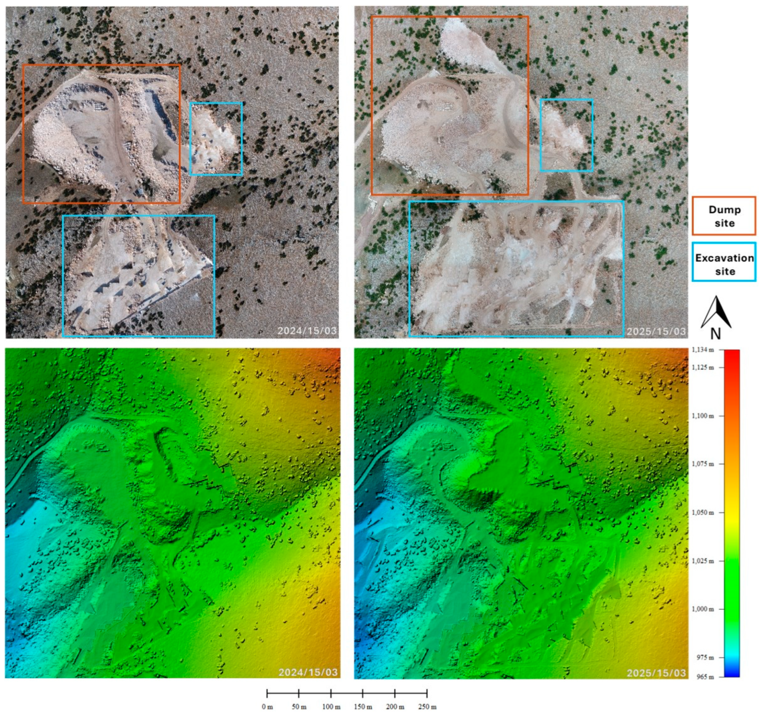
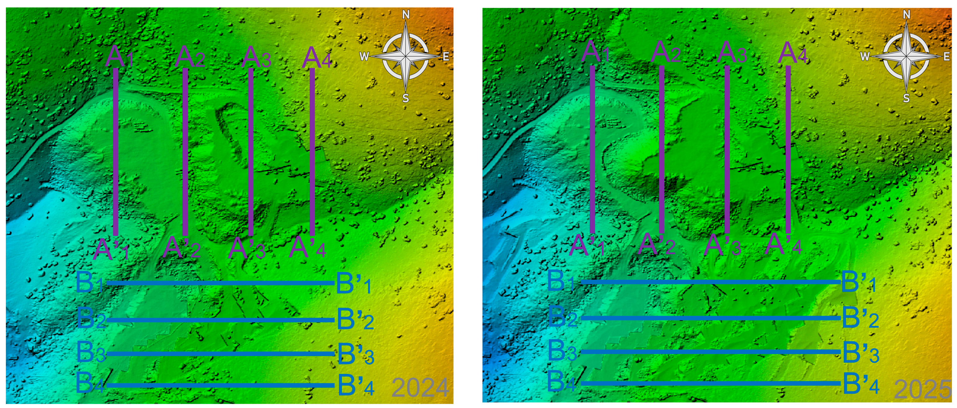
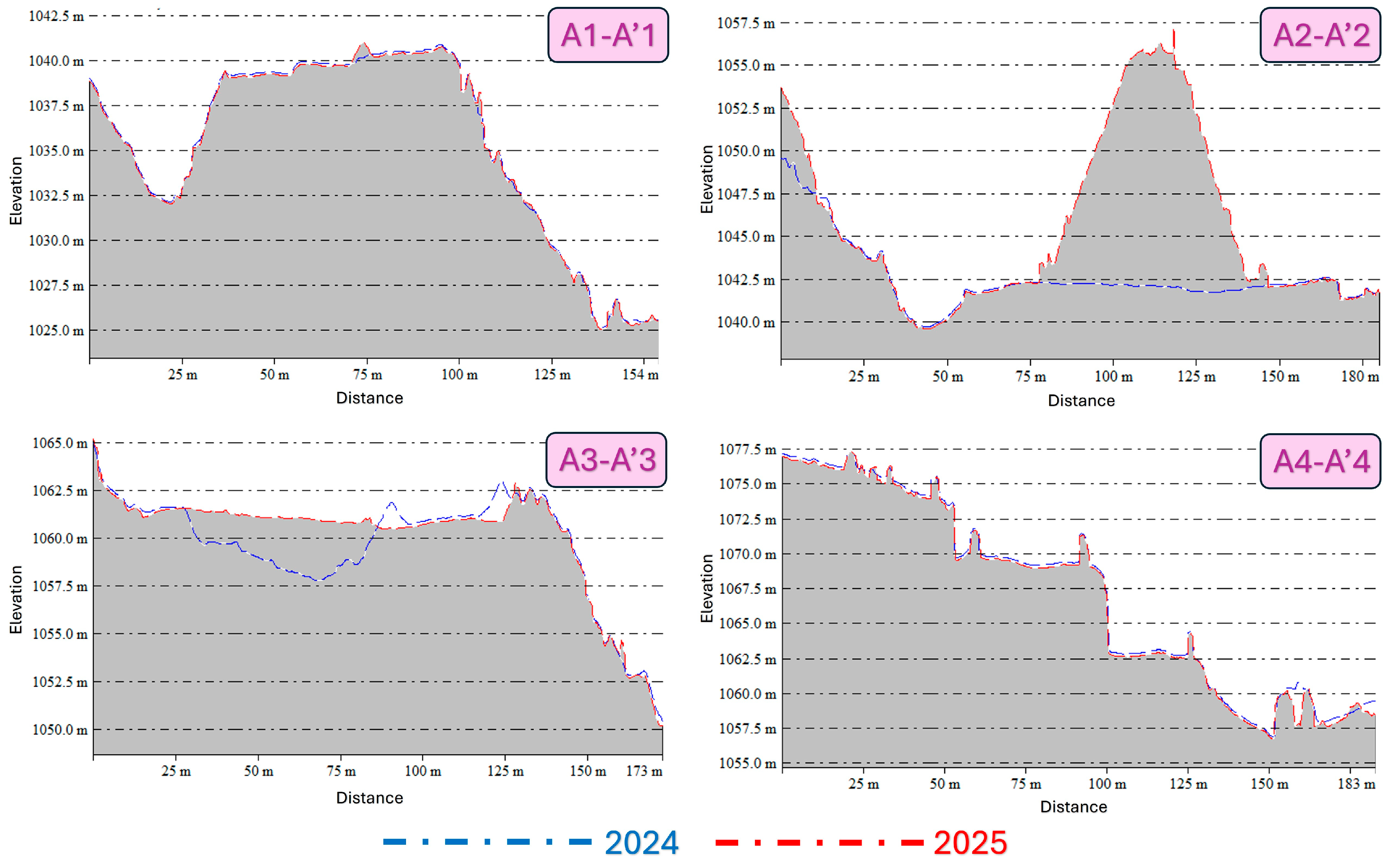
3.2. Change Detection, Volume and Surface Area Metric Analysis

The C2C analysis revealed surface changes between two time periods, allowing the identification of active zones and supporting the extraction of cross-section profiles (Figure 3).
Visual comparison techniques helped guide the gathering of cross-section profiles in the designated change zones using the C2C map. After visual inspection of the DEM data, the study area was split into two main zones: the upper part (active excavation/dumping area) and the lower part (secondary surface change zone). Given the predominance of significant vertical changes in the upper part, four vertically oriented profiles were created. This region is shown in purple. In the lower part, where slope transitions are more prevalent and surface change in the horizontal direction is more pronounced, four horizontal profiles were taken and are shown in blue (Figure 4).
Figure 5 presents the elevation profiles derived from the vertical sections A1–A4, whereas Figure 6 illustrates the horizontal sections B1–B4. Each plot compares elevation profiles extracted from the DEMs of 2024 and 2025. As shown, blue lines represent 2024 and red lines represent 2025. Note that in the plotted profiles, the vertical axis reflects actual elevation values but appears visually enhanced relative to the horizontal distance to emphasize subtle topographic variations.
As illustrated in Figure 5, vertical sections reveal pronounced topographic shifts caused by excavation and dumping, with elevation changes in some areas exceeding 10 m. The horizontal sections (Figure 6) exhibit the linearity of the configurations and subsurface transitions, where the topography usually rises and some transactions get smoother. This observation implies the possible involvement of processes including surface leveling or the distribution of piles of dump. These relative cross-sectional studies show that the directionally modeled elevation profiles also reflect surface change in the raster difference maps. The identification of dump and excavation sites provided essential first information for the categorization of sites for surface area and volume studies.
After visual and cross-sectional analysis, the M3C2 algorithm was applied to evaluate surface changes (Figure 7). This method calculates the distance between two point clouds along local normals and uses confidence intervals to assess statistical significance. The intensity of changes across the study area is shown in Figure 7a. Although point density was slightly reduced in the 2025 dataset, this did not affect the M3C2 analysis. Only statistically significant changes were interpreted.
The scalar field map (Figure 7d) displays elevation changes using spectral colors: positive for dumping, negative for excavation, and near zero for stability. Figure 7b shows the histogram of M3C2 distances, and Figure 7c presents the Gaussian distribution for stable zones.
As shown in Figure 7a, positive values indicate dumping, negative values indicate excavation, and values near zero represent stable areas. The scalar field map visualizes this distribution with spectral colors, highlighting a large dump pile in the north and excavation zones in the southeast. A Gaussian histogram analysis revealed a mean change of –0.005 m and a standard deviation of ±2.18 m, indicating asymmetric surface change concentrated near the center. Some areas showed extreme deviations of up to ±39 m, corresponding to intense local material transfer. Based on these findings, three surface classes were defined (Table 1). The thresholds of ±2.0 m and verticality > 0.25 used in M3C2 classification were based on typical excavation step heights and elevation patterns observed in UAV data. These thresholds help distinguish meaningful surface movement from noise and are consistent with values used in similar UAV-based mining studies.
The classified change map (Figure 7d) visualizes spatial differences using color codes: green for stable zones (±2 m), red for excavation, and blue for dumping. A separate Gaussian analysis for stable areas showed a mean deviation of −0.14 m and standard deviation of ±0.38 m, indicating minor variability with no significant effect on surface morphology.
Although no ground-control excavation logs or GPS-referenced validation points were available during the study period, spatial patterns were validated through a triangulated approach: (i) the known operational sequence of excavation and dumping activities provided by the site operator, (ii) visual comparison of orthomosaics and shaded DEMs from 2024 and 2025, and (iii) topographic consistency indicating surface addition (positive change) in dump zones and surface removal (negative change) in excavation areas.
The classification based on M3C2 analysis enabled the delineation of three morphodynamic classes: stable, dump, and excavation zones. Subsequent volume and area computations were carried out using CloudCompare’s 2.5D grid-based module (grid size: 0.5 m), which compared elevation differences between multi-temporal point clouds.
As summarized in Table 3, the stable zone (~150,104.5 m2) exhibited no significant elevation change (0.00 m3), serving as a geometric reference. The dump zone, primarily in the northwest, showed an accumulation of +7744.04 m3 over 7435.75 m2, while the excavation zone in the southeast revealed a material loss of –8359.72 m3 across 7844.50 m2. The matching rate in the dump areas (61.5%) was slightly lower due to surface irregularity from unconsolidated fragments, whereas excavation zones (71.4%) showed better matching thanks to smoother geometry and higher surface regularity.
These results validate the effectiveness of the ±2.0 m M3C2 threshold and demonstrate the ability of the proposed method to detect localized morphodynamic transitions within operational quarry settings.
The analysis of these three classes clarified the magnitude and direction of surface changes. Table 3 summarizes their spatial and volumetric effects.
The excavation and dump volumes are highly correlated, with a net volume difference of approximately 615.68 m3 being calculated. This discrepancy suggests that not all of the excavated material was utilized on-site or that a portion of it was transported to another location. Additionally, the surface areas exhibited a high degree of similarity, suggesting that the spatial distribution of excavation and dump interventions was uniform.
This analysis enabled a multifaceted evaluation of the morphological interventions on the site, encompassing both visual assessment and quantitative and comparative analysis. It also provided a scientific foundation for defining the scope of dumping and excavation activities.

3.3. Risk Analysis Results

A comprehensive analysis was performed in the dump zones using five key surface metrics: surface variation, roughness, verticality, planarity, and linearity (Figure 8, Figure 9, Figure 10, Figure 11 and Figure 12). These metrics revealed micro-scale topographic variations linked to physical processes affecting stability and settlement. The surface variation map (Figure 8) highlights localized anomalies, especially in areas with values above 0.20, which may indicate internal instability or insufficient compaction.
Suggesting a greater sensitivity to localized deformation, these high-variation zones are mostly found along the outer slopes and top boundary surfaces of the dump piles. Especially so, the red and yellow areas on the variation map match these important zones, stressing areas where surface heterogeneity and possible structural weakness are most noticeable.
The results of the roughness analysis (Figure 9) show a clear rise in surface irregularity inside particular localized zones. The highest roughness values—above ~1.14, shown in red—are mostly found along the peripheral slopes and crest zones of the dump piles, as the roughness map shows. These higher values point to either disrupted material consistency, coarse aggregates, or transitional surfaces where erosion or deposition might be actively occurring. Low-roughness areas (shaded in blue) on the other hand usually reflect more homogeneous and stable sections, maybe reflecting zones where compaction has already taken place.
The mean roughness is 0.240 with a standard deviation of 0.196, showing a right-skewed distribution. While most areas are smooth, a small portion exhibits significant roughness, possibly indicating erosion risk, poor compaction, or post-depositional instability. Roughness mapping complements surface variation analysis by enhancing spatial understanding of terrain stability, deformation risk, and operational safety.
Representing the degree to which a surface deviates from the horizontal plane, the verticality analysis results (Figure 10) offer an angular analysis of the surface normals produced from the dense point clouds. Identifying steep slopes, escarpments, or abrupt structural transitions within the dump areas—all of which may have major effects on slope stability and erosion susceptibility—depends on this measure.
Red zones with verticality values above 0.35 often occur on outer flanks, indicating steep embankments from dumping, material shifts, or erosion. Blue and green zones (<0.18) indicate flat, stable surfaces. The bimodal histogram—with peaks near 0.05–0.10 and 0.20–0.25—reflects a mix of planar areas and steep inclines. This implies the presence of large flat surfaces and steep slopes within the field.
Reflecting a dominantly low-sloped morphology with isolated high-angle features, the global mean verticality is computed as 0.119 with a standard deviation of 0.109. Particularly in assessing structurally vulnerable areas and guiding dump site management strategies, verticality analysis improves the knowledge of terrain geometry when taken in line with roughness and surface variation maps.
Linearity analysis (Figure 11) displays the spatial distribution of structural discontinuities across dump surfaces. This metric offers insight into material coherence, anisotropy, and potential mechanical discontinuities by measuring the alignment of points along linear features.
Elevated linearity values, especially observed along pile edges and slope toes, suggest the presence of fracture networks or early-stage mechanical discontinuities. The histogram confirms that these features are scattered randomly, indicating no consistent spatial pattern.
Such irregularities result in isolated micro-zones with higher risk potential, which could signal localized instabilities. When combined with roughness and verticality data, the linearity metric becomes a valuable tool for identifying structurally weak zones, particularly in areas where directional forces or water pathways concentrate stress. This spatial insight can guide targeted stabilization and monitoring strategies within complex dump terrains.
The planarity analysis (Figure 12) reveals that the inner regions of the rubble piles generally maintain higher planarity values, indicative of relatively stable and well-settled surfaces. This metric is instrumental in distinguishing between well-structured, flat surfaces and irregular, morphologically unstable regions across the dump sites. High planarity values—depicted in orange to red—dominate the central, interior sections of the dump piles, with a global mean of 0.731 and a standard deviation of 0.210. These elevated values suggest the presence of relatively flat and uniformly compacted areas, likely resulting from controlled dumping and mechanical surface stabilization. Such regions are indicative of improved structural coherence and lower deformation potential.
Conversely, low planarity values (blue to green) are concentrated near the outer margins and transitional edges of the dump piles. These areas tend to exhibit uneven settlement, inconsistent compaction, and surface undulations—often due to edge effects or insufficient mechanical leveling.
The negatively skewed histogram supports this by showing that while high planarity values dominate, some isolated low-planarity zones exist. These anomalies may correspond to unstable slopes or regions affected by drainage-induced deformation.
When interpreted together with linearity and verticality maps, planarity assessment enhances the spatial understanding of terrain uniformity and reveals potential zones of structural irregularity that may compromise long-term dump stability.
The classified risk zones were qualitatively validated through field observations; however, additional quantitative validation will be pursued in future monitoring campaigns.

4. Discussion, Limitations, and Future Work

This study demonstrates the effectiveness of advanced geospatial analysis and UAV-based photogrammetry in evaluating surface change and morphological stability within an operational open-pit marble quarry. The integration of multi-temporal SfM workflows with point cloud and raster-based GIS analyses contributes meaningfully to the ongoing discourse on high-resolution digital monitoring practices under the scope of Mining 4.0.
This morphometric UAV-based workflow complements traditional empirical and geotechnical slope stability assessment methods by providing high-resolution, reproducible spatial datasets. The combination of roughness, verticality, planarity, and linearity metrics offers a multi-dimensional view of surface integrity, which is crucial for proactive mine safety planning under the principles of Mining 4.0.
The findings directly fulfill the study’s initial aim by illustrating how UAV-derived morphometric metrics enhance slope stability assessment and enable risk-informed planning.
Unlike traditional UAV applications limited to volume estimation or visual inspection, this study employs a detailed morphometric framework incorporating multiple geometric metrics. These metrics, derived from dense point clouds and processed in open-source software (CloudCompare), offer nuanced insight into surface heterogeneity and potential instability in anthropogenically modified terrains, such as waste dumps. A methodological development in assessing surface irregularities and early deformation zones is achieved by combining roughness and verticality analyses on segmented dump zones.
The analysis confirmed that zones of unstable slope transitions and dump boundaries corresponded with regions exhibiting high surface variation and verticality values. This result supports previous findings by Jia et al. (2022) [42], Hao et al. (2023) [43], and Chand et al. (2024) [55], highlighting the vulnerability of complex slope geometries to localized failure. Additionally, histogram-based statistical evaluations of metric distributions offered further validation for differentiating stable and unstable micro-topographies in dump areas.
Surface models derived from UAV-based SfM were validated through spatial accuracy (via CPs and RMSE) and temporal alignment (via ICP-based registration). Internal (bundle adjustment, reprojection error) and external (GCP/CP RMSE) validations were conducted using standard photogrammetric practices. Visual inspection confirmed continuity in critical zones. The low RMSE values (<4 cm) and alignment error (2.1 cm) between epochs support the effectiveness of the method for high-precision monitoring, in line with Duarte et al. (2021) [45] and Xiang et al. (2018) [60].
Recently dumped, low-texture waste rock surfaces caused a reduction in dense point generation for the 2025 dataset. This limitation reflects the inherent dependency of SfM photogrammetry on surface texture and image contrast, as widely reported in prior studies [3,9].
This study introduces a significant methodological advancement by adopting the M3C2 algorithm instead of traditional DEM differencing or raster-based volume estimation. M3C2 measures surface change perpendicularly to local normals and integrates confidence intervals, enabling statistically supported distinction among excavation, dump, and stable zones. As demonstrated by Esposito et al. (2017) [59] and Tangadzani et al. (2024) [65], this method more accurately captures terrain deformation. Liu et al. (2023) [66] further emphasized the superior capability of M3C2 in detecting complex deformations in heterogeneous and vegetated areas. These findings justified the selection of M3C2 as the core method for 3D topographic change assessment. Additionally, point cloud segmentation based on scalar fields, followed by morphometric risk mapping, offers a repeatable framework to identify unstable areas without ground-based measurements.
The findings align with and expand on earlier research, highlighting the added value of morphometric segmentation for refined risk zoning beyond conventional volume analyses. Consistent with Tucci et al. (2019) [57], who applied UAV photogrammetry for volume estimation in recyclable waste sites, this study confirms the reliability of UAV-based methods for detailed surface monitoring. Both studies emphasize advantages such as increased safety, repeatability, and reduced survey time. The implementation of a similar 2.5D raster-based volume calculation further supports the adaptability of this approach across different materials and terrains.
This study’s results are consistent with those of Özdaş et al. (2024) [67], who found that M3C2 outperforms DoD by capturing full 3D displacement vectors, while DoD is limited to vertical change. Their findings reinforce the morphometric segmentation and stability assessment strategy adopted here. Similarly, Bar and McQuillan (2021) [58] relied on empirical classifications, whereas this study applies surface geometry to define instability zones. This highlights the potential of UAV-based topographic data to augment or improve upon traditional geotechnical methods. In line with Hao et al. (2023) [43], who used UAV photogrammetry to detect structural discontinuities, this research confirms the reliability of SfM-based morphometric analysis in open-pit slope risk assessment.
The analysis revealed a net volume imbalance of approximately 615 m3 between excavation and dumping zones, potentially due to off-site transfer or material compaction. This highlights UAV-derived point clouds’ capability not only in monitoring surface change but also in detecting process inefficiencies. Although measurement sensitivity may contribute to this discrepancy, field observations suggest that part of the excavated material was stored outside the survey boundary. Additionally, compaction in granular dump areas may have reduced the visible volume. Future campaigns can reduce such uncertainty by combining UAV data with bulk density tests, equipment logs, and volume validations.
Early warning systems, slope management plans, and field intervention prioritizing can benefit much from the high-resolution surface change detection and morphometric analysis outputs produced in this work. The quantified surface change monitoring results directly inform operational decision making by supporting the design of slope stabilization measures, scheduling of excavation and dumping operations, and timely on-site interventions, thereby enhancing safety and efficiency. For example, the integration of roughness and verticality maps across spatial overlay has allowed the identification of multi-risk zones along dump peripheries, which might otherwise remain undetected by conventional visual inspection or raster-based slope analysis.
The open-source and repeatable nature of the proposed workflow makes it suitable for routine monitoring, especially in medium-scale quarries with limited resources where frequent LiDAR surveys are not feasible. The integration of advanced spatial analysis with UAV data demonstrates the method’s capacity to generate decision-ready, engineering-grade outputs. This supports the increasing interest in scalable and cost-effective digital mine monitoring systems [13,34].
Ajayi and Ajulo (2021) [44] directly compared UAV photogrammetry with conventional total station surveys on stockpiles, supporting the results of this study on the accuracy and efficiency of UAV-based volumetric modeling. Although their work concentrated on volume-only analysis, this study extends this application by including morphometric parameters for risk zoning and slope stability assessment.
One should be aware of several restrictions in understanding the outcomes of this research. This study used two UAV surveys conducted approximately one year apart to monitor cumulative surface changes; however, more frequent acquisitions would allow detection of short-term deformations and sudden slope instabilities. Sub-annual or quarterly UAV missions are recommended for future projects to enhance dynamic hazard monitoring and to provide timely early warnings.
Integrating multi-sensor data—such as thermal imagery, multispectral bands, or TLS scans—could improve the understanding of instability mechanisms. Additionally, using machine learning or clustering algorithms to classify risk zones based on morphometric features presents a promising avenue for future research.
This work additionally focuses on morphometric and spatially descriptive analyses produced from UAV-based point clouds. Geometric surface characterization dominated attention, thus inferential statistical techniques including hypothesis testing, classification models, or regression were not used. Furthermore, only two time points were used while multi-temporal data was obtained, so restricting the temporal resolution of deformation detection.
It should be noted that the dump areas analyzed in this study refer to openly piled, unconsolidated overburden and waste marble fragments, rather than compacted or engineered fills. Therefore, classical geotechnical parameters (e.g., friction angle, cohesion) were not considered within the scope of this surface-level morphometric analysis. However, future studies may integrate such parameters in extended stability modeling to complement the morphometric framework proposed here.
One more restriction relates to the absence of external validation derived from GNSS ground control points or excavation logs. Future studies will integrate in situ geotechnical measurements, GNSS surveys, and repeated UAV campaigns to quantitatively validate and further refine the proposed risk classification framework. In addition, deploying temporary CP within critical movement zones could provide straightforward and practical ground truth for future monitoring.
Second, the techniques were implemented on an open-pit marble site; although the workflow is theoretically transferable, depending on geology, surface texture, and mining techniques, their efficacy may vary among different mine types. Thus, generalizing the outcomes calls for care. Third, the study lacked external validation including GNSS ground truthing or excavation logs; hence, future research should combine such data sources to improve volumetric validation and classification accuracy. Lack of subsurface geological data, including ground density, material cohesion, or lithological stratification, adds still another restriction to the present work. Although surface measures obtained from UAV data offer significant geometric indicators, subsurface characteristics naturally affect slope stability. To increase the accuracy and dependability of safety assessments, future research should seek to combine ground-based geotechnical investigations with photogrammetric surface analysis.
This study aligns with findings by Cirillo et al. (2024) [68], who applied UAV-based 3D point clouds for rockfall hazard assessment along coastal cliffs. Their use of digital outcrop modeling and stereographic kinematic analysis successfully identified failure zones. Although their focus was on natural cliffs, the similar application of CloudCompare and GIS tools supports the methodological strength of this study for assessing instability in modified open-pit settings.

5. Conclusions

This study demonstrated that integrating UAV-based photogrammetry with advanced point cloud and geospatial analyses enables effective monitoring of morphological changes and stability risks in active open-pit marble quarries. The results confirm that high-resolution, engineering-grade datasets can be reliably generated when UAV–SfM workflows are supported by rigorous accuracy controls and metric-based evaluations.
In this regard, the ICP alignment error (2.09 cm) and DEM accuracy (3.85 cm RMSE) were found to be negligible compared to elevation differences exceeding 7 m in dump zones, accounting for less than 1% of total change. These results validate the reliability of the UAV photogrammetric outputs for engineering-grade volumetric and slope stability analyses.
The use of roughness, verticality, surface variation, planarity, and linearity metrics provided deeper insight into the site’s evolving morphology, surpassing the capabilities of traditional volume-based approaches. High surface irregularity and steep slope gradients were consistently associated with elevated instability risk, highlighting the value of multi-metric characterization for proactive hazard detection.
The study also emphasized the practical advantages of using open-source tools like CloudCompare, supporting scalable and cost-effective monitoring in operational mining. The proposed workflow enhances excavation and dumping practices while also serving environmental monitoring, early warning systems, and safety planning.
The structured integration of UAV photogrammetry with multi-metric spatial analysis advances geomorphological monitoring in open-pit mining. While individual techniques like M3C2 or roughness are well-established, their coordinated use for proactive hazard detection in marble quarry environments offers a novel contribution. The workflow demonstrates strong potential for repeatability, scalability, and adaptation across other high-risk monitoring contexts.
Although the current workflow remains semi-automated, future research should aim to develop fully automated pipelines for segmentation, metric calculation, and risk classification. Open-source tools such as CloudCompare with Python 3.13.4, PDAL, or machine learning models could facilitate this, increasing the efficiency and transferability of UAV-based mine monitoring systems.
In summary, this integrated methodology illustrates how UAV–SfM photogrammetry, advanced point cloud analysis, and morphometric risk mapping can enhance safety and operational efficiency, aligning with the broader objectives of scalable digital mine monitoring under Mining 4.0.

Author Contributions

Conceptualization, A.Y.Y. and H.İ.Ş.; methodology, A.Y.Y. and H.İ.Ş.; software, A.Y.Y. and H.İ.Ş.; validation, A.Y.Y.; formal analysis, A.Y.Y.; investigation, A.Y.Y. and H.İ.Ş.; resources, H.İ.Ş.; data curation, A.Y.Y.; writing—original draft preparation, A.Y.Y. and H.İ.Ş.; writing—review and editing, A.Y.Y. and H.İ.Ş.; visualization, A.Y.Y.; supervision, A.Y.Y. and H.İ.Ş. All authors have read and agreed to the published version of the manuscript.

Funding

This research received no external funding.

Data Availability Statement

The data that support the findings of this study are available from the corresponding author upon reasonable request.

Acknowledgments

The authors would like to express their sincere gratitude to Mürsel Burak Çelik, a surveying engineer and the owner of İlkim Harita Müh. Değ. Eml. İnş. San. ve Tic. Ltd. Şti., for providing hardware, software, and archival support. The authors also extend their thanks to the staff of Şahin Madencilik Müh. Müş. Tic. Ltd. Şti. for their valuable assistance.

Conflicts of Interest

The authors declare no conflicts of interest.

References

  1. Badri, A.; Nadeau, S.; Gbodossou, A. Integration of OHS into Risk Management in an Open-Pit Mining Project in Quebec (Canada). Minerals 2011, 1, 3–29. [Google Scholar] [CrossRef]
  2. Khrais, S.K.; Yared, T.E.; Saifan, N.M.; Al-Hawari, T.H.; Dweiri, F. Occupational Safety Assessment for Surface Mine Systems: The Case in Jordan. Safety 2024, 10, 40. [Google Scholar] [CrossRef]
  3. Fabris, M.; Monego, M. A Drone-Based Structure from Motion Survey, Topographic Data, and Terrestrial Laser Scanning Acquisitions for the Floodgate Gaps Deformation Monitoring of the Modulo Sperimentale Elettromeccanico System (Venice, Italy). Drones 2024, 8, 598. [Google Scholar] [CrossRef]
  4. Liu, W.; Sheng, G.; Kang, X.; Yang, M.; Li, D.; Wu, S. Slope Stability Analysis of Open-Pit Mine Considering Weathering Effects. Appl. Sci. 2024, 14, 8449. [Google Scholar] [CrossRef]
  5. Ren, H.; Zhao, Y.; Xiao, W.; Hu, Z. A Review of UAV Monitoring in Mining Areas: Current Status and Future Perspectives. Int. J. Coal Sci. Technol. 2019, 6, 320–333. [Google Scholar] [CrossRef]
  6. Oliveros-Sepúlveda, D.; Bascompta-Massanés, M.; Franco-Sepúlveda, G. Environmental and Closure Costs in Strategic Mine Planning, Models, Regulations, and Policies. Resources 2025, 14, 41. [Google Scholar] [CrossRef]
  7. Westoby, M.J.; Brasington, J.; Glasser, N.F.; Hambrey, M.J.; Reynolds, J.M. ‘Structure-from-Motion’ Photogrammetry: A Low-Cost, Effective Tool for Geoscience Applications. Geomorphology 2012, 179, 300–314. [Google Scholar] [CrossRef]
  8. Zapico, I.; Laronne, J.B.; Sánchez Castillo, L.; Martín Duque, J.F. Improvement of Workflow for Topographic Surveys in Long Highwalls of Open Pit Mines with an Unmanned Aerial Vehicle and Structure from Motion. Remote Sens. 2021, 13, 3353. [Google Scholar] [CrossRef]
  9. Leal-Alves, D.C.; Weschenfelder, J.; Albuquerque, M.D.G.; Espinoza, J.M.D.A.; Ferreira-Cravo, M.; Almeida, L.P.M.D. Digital elevation model generation using UAV-SfM photogrammetry techniques to map sea-level rise scenarios at Cassino Beach, Brazil. SN Appl. Sci. 2020, 2, 2181. [Google Scholar] [CrossRef]
  10. Battulwar, R.; Winkelmaier, G.; Valencia, J.; Naghadehi, M.Z.; Peik, B.; Abbasi, B.; Parvin, B.; Sattarvand, J. A Practical Methodology for Generating High-Resolution 3D Models of Open-Pit Slopes Using UAVs: Flight Path Planning and Optimization. Remote Sens. 2020, 12, 2283. [Google Scholar] [CrossRef]
  11. Qi, J.; Lin, E.S.; Tan, P.Y.; Zhang, X.; Ho, R.; Sia, A.; Waykool, R. Applying 3D Spatial Metrics for Landscape Planning: Creating and Measuring Landscape Scenarios by a Point Cloud-Based Approach. Ecol. Inform. 2024, 79, 102436. [Google Scholar] [CrossRef]
  12. Liu, B.; Liu, X.; Wan, H.; Ma, Y.; Lu, L. Long-Term Quantitative Analysis of the Temperature Vegetation Dryness Index to Assess Mining Impacts on Surface Soil Moisture: A Case Study of an Open-Pit Mine in Arid and Semiarid China. Appl. Sci. 2025, 15, 1850. [Google Scholar] [CrossRef]
  13. Zhang, L.; Zhai, Z.; Zhou, Y.; Liu, S.; Wang, L. The Landscape Pattern Evolution of Typical Open-Pit Coal Mines Based on Land Use in Inner Mongolia of China during 20 Years. Sustainability 2022, 14, 9590. [Google Scholar] [CrossRef]
  14. Krzyszowska Waitkus, A. Sustainable Reclamation Practices for a Large Surface Coal Mine in Shortgrass Prairie, Semiarid Environment (Wyoming, USA): Case Study. Int. J. Coal Sci. Technol. 2022, 9, 32. [Google Scholar] [CrossRef]
  15. Wang, S.; Bai, Z.; Lv, Y.; Zhou, W. Monitoring Extractive Activity-Induced Surface Subsidence in Highland and Alpine Opencast Coal Mining Areas with Multi-Source Data. Remote Sens. 2022, 14, 3442. [Google Scholar] [CrossRef]
  16. Kabadayı, A. Maden Sahasının İnsansız Hava Aracı Yardımıyla Fotogrametrik Yöntemle Haritalanması. Türkiye İn-sansız Hava Araçları Dergisi 2022, 4, 19–23. [Google Scholar] [CrossRef]
  17. Frid, M.; Frid, V. A Case Study of the Integration of Ground-Based and Drone-Based Ground-Penetrating Radar (GPR) for an Archaeological Survey in Hulata (Israel): Advancements, Challenges, and Applications. Appl. Sci. 2024, 14, 4280. [Google Scholar] [CrossRef]
  18. Almohsen, A.S. Challenges Facing the Use of Remote Sensing Technologies in the Construction Industry: A Review. Buildings 2024, 14, 2861. [Google Scholar] [CrossRef]
  19. Iglhaut, J.; Cabo, C.; Puliti, S.; Piermattei, L.; O’Connor, J.; Rosette, J. Structure from Motion Photogrammetry in Forestry: A Review. Curr. For. Rep. 2019, 5, 155–168. [Google Scholar] [CrossRef]
  20. Kalacska, M.; Arroyo-Mora, J.P.; Lucanus, O. Comparing UAS LiDAR and Structure-from-Motion Photogrammetry for Peatland Mapping and Virtual Reality (VR) Visualization. Drones 2021, 5, 36. [Google Scholar] [CrossRef]
  21. Bartlett, B.; Santos, M.; Dorian, T.; Moreno, M.; Trslic, P.; Dooly, G. Real-Time UAV Surveys with the Modular Detection and Targeting System: Balancing Wide-Area Coverage and High-Resolution Precision in Wildlife Monitoring. Remote Sens. 2025, 17, 879. [Google Scholar] [CrossRef]
  22. Li, Q.; Ma, Y.; Anderson, J.; Curry, J.; Shan, J. Towards Uniform Point Density: Evaluation of an Adaptive Terrestrial Laser Scanner. Remote Sens. 2019, 11, 880. [Google Scholar] [CrossRef]
  23. Abegg, M.; Kükenbrink, D.; Zell, J.; Schaepman, M.E.; Morsdorf, F. Terrestrial Laser Scanning for Forest Inventories—Tree Diameter Distribution and Scanner Location Impact on Occlusion. Forests 2017, 8, 184. [Google Scholar] [CrossRef]
  24. Ferreira, E.; Grilo, V.; Braun, J.; Santos, M.; Pereira, A.I.; Costa, P.; Lima, J. Development of a Low-Cost 3D Mapping Technology with 2D LIDAR for Path Planning Based on the A* Algorithm. In Iberian Robotics Conference; Springer Nature: Cham, Switzerland, 2023; pp. 53–66. [Google Scholar] [CrossRef]
  25. Shi, B.; Lin, W.; Ouyang, W.; Shen, C.; Sun, S.; Sun, Y.; Sun, L. BA-CLM: A Globally Consistent 3D LiDAR Mapping Based on Bundle Adjustment Cost Factors. Sensors 2024, 24, 5554. [Google Scholar] [CrossRef] [PubMed]
  26. Hamal, S.N.G.; Ulvi, A. Yersel Lazer Tarama ile Mimari Koruma ve Restorasyon Süreçlerinin Dijitalleştirilmesi. Türkiye Lidar Derg. 2024, 6, 66–73. [Google Scholar] [CrossRef]
  27. Chidi, C.L.; Zhao, W.; Chaudhary, S.; Xiong, D.; Wu, Y. Sensitivity Assessment of Spatial Resolution Difference in DEM for Soil Erosion Estimation Based on UAV Observations: An Experiment on Agriculture Terraces in the Middle Hill of Nepal. ISPRS Int. J. Geo Inf. 2021, 10, 28. [Google Scholar] [CrossRef]
  28. Delaney, B.; Tansey, K.; Whelan, M. Satellite Remote Sensing Techniques and Limitations for Identifying Bare Soil. Remote Sens. 2025, 17, 630. [Google Scholar] [CrossRef]
  29. Fabris, M.; Fontana Granotto, P.; Monego, M. Expeditious Low-Cost SfM Photogrammetry and a TLS Survey for the Structural Analysis of Illasi Castle (Italy). Drones 2023, 7, 101. [Google Scholar] [CrossRef]
  30. Haghjouei, H.; Kantoush, S.A.; Beiramipour, S.; Rahimpour, M.; Qaderi, K. Experimental Study Demonstrating a Cost-Effective Approach for Generating 3D-Enhanced Models of Sediment Flushing Cones Using Model-Based SFM Photogrammetry. Water 2022, 14, 1588. [Google Scholar] [CrossRef]
  31. Kasprzak, M.; Jancewicz, K.; Michniewicz, A. UAV and SfM in Detailed Geomorphological Mapping of Granite Tors: An Example of Starościńskie Skały (Sudetes, SW Poland). Pure Appl. Geophys. 2018, 175, 3193–3207. [Google Scholar] [CrossRef]
  32. Hilgendorf, Z.; Marvin, M.C.; Turner, C.M.; Walker, I.J. Assessing Geomorphic Change in Restored Coastal Dune Ecosystems Using a Multi-Platform Aerial Approach. Remote Sens. 2021, 13, 354. [Google Scholar] [CrossRef]
  33. Bi, R.; Gan, S.; Yuan, X.; Li, R.; Gao, S.; Yang, M.; Luo, W.; Hu, L. Multi-View Analysis of High-Resolution Geomorphic Features in Complex Mountains Based on UAV–LiDAR and SfM–MVS: A Case Study of the Northern Pit Rim Structure of the Mountains of Lufeng, China. Appl. Sci. 2023, 13, 738. [Google Scholar] [CrossRef]
  34. Villarreal, M.L.; Bishop, T.B.; Sankey, T.T.; Smith, W.K.; Burgess, M.A.; Caughlin, T.T.; Yao, E.H. Applications of Unoccupied Aerial Systems (UAS) in Landscape Ecology: A Review of Recent Research, Challenges and Emerging Opportunities. Landsc. Ecol. 2025, 40, 43. [Google Scholar] [CrossRef]
  35. Bartmiński, P.; Siłuch, M.; Kociuba, W. The Effectiveness of a UAV-Based LiDAR Survey to Develop Digital Terrain Models and Topographic Texture Analyses. Sensors 2023, 23, 6415. [Google Scholar] [CrossRef] [PubMed]
  36. Panara, Y.; Menegoni, N.; Finkbeiner, T.; Zühlke, R.; Vahrenkamp, V. High-Resolution Analysis of 3D Fracture Networks from Digital Outcrop Models, Correlation to Plate-Tectonic Events and Calibration of Subsurface Models (Jurassic, Arabian Plate). Mar. Pet. Geol. 2024, 167, 106998. [Google Scholar] [CrossRef]
  37. Hasegawa, H.; Sujaswara, A.A.; Kanemoto, T.; Tsubota, K. Possibilities of Using UAV for Estimating Earthwork Volumes during Process of Repairing a Small-Scale Forest Road, Case Study from Kyoto Prefecture, Japan. Forests 2023, 14, 677. [Google Scholar] [CrossRef]
  38. Kim, Y.H.; Shin, S.S.; Lee, H.K.; Park, E.S. Field Applicability of Earthwork Volume Calculations Using Unmanned Aerial Vehicle. Sustainability 2022, 14, 9331. [Google Scholar] [CrossRef]
  39. Trepekli, K.; Balstrøm, T.; Friborg, T.; Fog, B.; Allotey, A.N.; Kofie, R.Y.; Møller-Jensen, L. UAV-Borne, LiDAR-Based Elevation Modelling: A Method for Improving Local-Scale Urban Flood Risk Assessment. Nat. Hazards 2022, 113, 423–451. [Google Scholar] [CrossRef]
  40. Lee, K.; Lee, W.H. Earthwork Volume Calculation, 3D Model Generation, and Comparative Evaluation Using Vertical and High-Oblique Images Acquired by Unmanned Aerial Vehicles. Aerospace 2022, 9, 606. [Google Scholar] [CrossRef]
  41. Meng, X.; Wang, T.; Cheng, D.; Su, W.; Yao, P.; Ma, X.; He, M. Enhanced Point Cloud Slicing Method for Volume Calculation of Large Irregular Bodies: Validation in Open-Pit Mining. Remote Sens. 2023, 15, 5006. [Google Scholar] [CrossRef]
  42. Jia, H.; Zhu, G.; Guo, L.; He, J.; Liang, B.; He, S. An Improved Point Clouds Model for Displacement Assessment of Slope Surface by Combining TLS and UAV Photogrammetry. Appl. Sci. 2022, 12, 4320. [Google Scholar] [CrossRef]
  43. Hao, J.; Zhang, X.; Wang, C.; Wang, H.; Wang, H. Application of UAV Digital Photogrammetry in Geological Investigation and Stability Evaluation of High-Steep Mine Rock Slope. Drones 2023, 7, 198. [Google Scholar] [CrossRef]
  44. Ajayi, O.G.; Ajulo, J. Investigating the applicability of unmanned aerial vehicles (UAV) photogrammetry for the estimation of the volume of stockpiles. Quaest. Geogr. 2021, 40, 25–38. [Google Scholar] [CrossRef]
  45. Duarte, J.; Rodrigues, M.F.; Santos Baptista, J. Data Digitalisation in the Open-Pit Mining Industry: A Scoping Review. Arch. Comput. Methods Eng. 2021, 28, 3167–3181. [Google Scholar] [CrossRef]
  46. Bill, R.; Blankenbach, J.; Breunig, M.; Haunert, J.H.; Heipke, C.; Herle, S.; Werner, M. Geospatial Information Research: State of the Art, Case Studies and Future Perspectives. PFG–J. Photogramm. Remote Sens. Geoinf. Sci. 2022, 90, 349–389. [Google Scholar] [CrossRef]
  47. Zupancich, A.; Mutri, G.; Caricola, I.; Carra, M.L.; Radini, A.; Cristiani, E. The Application of 3D Modeling and Spatial Analysis in the Study of Groundstones Used in Wild Plants Processing. Archaeol. Anthropol. Sci. 2019, 11, 4801–4827. [Google Scholar] [CrossRef]
  48. Hamal, S.N.G.; Ulvi, A. 3B Kent Modelleri Oluşturma Sürecinde İHA Fotogrametrisi ve CBS Entegrasyonu: Mersin Üniversitesi Çiftlikköy Kampüsü Örneği. Türkiye Coğrafi Bilgi Sist. Derg. 2022, 4, 97–105. [Google Scholar] [CrossRef]
  49. Kyriou, A.; Nikolakopoulos, K.G.; Koukouvelas, I.K. Timely and Low-Cost Remote Sensing Practices for the Assessment of Landslide Activity in the Service of Hazard Management. Remote Sens. 2022, 14, 4745. [Google Scholar] [CrossRef]
  50. Gudowicz, J.; Paluszkiewicz, R. MAT: GIS-Based Morphometry Assessment Tools for Concave Landforms. Remote Sens. 2021, 13, 2810. [Google Scholar] [CrossRef]
  51. Hu, X.; Xia, B.; Guo, Y.; Yin, Y.; Chen, H. Comprehensive Monitoring of Construction Spoil Disposal Areas in High-Speed Railways Utilizing Integrated 3S Techniques. Appl. Sci. 2025, 15, 762. [Google Scholar] [CrossRef]
  52. Kölle, M.; Walter, V.; Sörgel, U. Building a Fully-Automatized Active Learning Framework for the Semantic Segmentation of Geospatial 3D Point Clouds. PFG–J. Photogramm. Remote Sens. Geoinf. Sci. 2024, 92, 131–161. [Google Scholar] [CrossRef]
  53. Dong, Y.; Li, Y.; Hou, M. The Point Cloud Semantic Segmentation Method for the Ming and Qing Dynasties’ Official-Style Architecture Roof Considering the Construction Regulations. ISPRS Int. J. Geo Inf. 2022, 11, 214. [Google Scholar] [CrossRef]
  54. Pellerin Le Bas, X.; Froideval, L.; Mouko, A.; Conessa, C.; Benoit, L.; Perez, L. A New Open-Source Software to Help Design Models for Automatic 3D Point Cloud Classification in Coastal Studies. Remote Sens. 2024, 16, 2891. [Google Scholar] [CrossRef]
  55. Chand, K.; Mankar, A.K.; Koner, R.; Naresh, A.R.V.S. Dump Slope Change Detection and Displacement Monitoring Using UAV Close-Range Photogrammetry. Sādhanā 2024, 49, 277. [Google Scholar] [CrossRef]
  56. Bamford, T.; Medinac, F.; Esmaeili, K. Continuous Monitoring and Improvement of the Blasting Process in Open Pit Mines Using Unmanned Aerial Vehicle Techniques. Remote Sens. 2020, 12, 2801. [Google Scholar] [CrossRef]
  57. Tucci, G.; Gebbia, A.; Conti, A.; Fiorini, L.; Lubello, C. Monitoring and Computation of the Volumes of Stockpiles of Bulk Material by Means of UAV Photogrammetric Surveying. Remote Sens. 2019, 11, 1471. [Google Scholar] [CrossRef]
  58. Bar, N.; McQuillan, A. Q-slope Application to Coal Mine Stability. IOP Conf. Ser.: Earth Environ. Sci. 2021, 833, 012043. [Google Scholar] [CrossRef]
  59. Esposito, G.; Mastrorocco, G.; Salvini, R.; Oliveti, M.; Starita, P. Application of UAV Photogrammetry for the Multi-Temporal Estimation of Surface Extent and Volumetric Excavation in the Sa Pigada Bianca Open-Pit Mine, Sardinia, Italy. Environ. Earth Sci. 2017, 76, 103. [Google Scholar] [CrossRef]
  60. Xiang, J.; Chen, J.; Sofia, G.; Tian, Y.; Tarolli, P. Open-Pit Mine Geomorphic Changes Analysis Using Multi-Temporal UAV Survey. Environ. Earth Sci. 2018, 77, 1–18. [Google Scholar] [CrossRef]
  61. Padró, J.C.; Cardozo, J.; Montero, P.; Ruiz-Carulla, R.; Alcañiz, J.M.; Serra, D.; Carabassa, V. Drone-Based Identification of Erosive Processes in Open-Pit Mining Restored Areas. Land 2022, 11, 212. [Google Scholar] [CrossRef]
  62. Cheng, G.; Huang, Y.; Li, X.; Lyu, S.; Xu, Z.; Zhao, H.; Zhao, Q.; Xiang, S. Change Detection Methods for Remote Sensing in the Last Decade: A Comprehensive Review. Remote Sens. 2024, 16, 2355. [Google Scholar] [CrossRef]
  63. Zhu, X.; Yang, H.; Bian, H.; Mei, Y.; Zhang, B.; Xue, P. Multi-Scalar Oblique Photogrammetry-Supported 3D webGIS Approach to Preventive Mining-Induced Deformation Analysis. Appl. Sci. 2023, 13, 13342. [Google Scholar] [CrossRef]
  64. Stilla, U.; Xu, Y. Change Detection of Urban Objects Using 3D Point Clouds: A Review. ISPRS J. Photogramm. Remote Sens. 2023, 197, 228–255. [Google Scholar] [CrossRef]
  65. Tangadzani, J.P.; Paradzayi, C.; Muromo, T.G. Application of UAV-Based Photogrammetry in Monitoring Slope Deformations in Open Pit Mining Environments: A Systematic Review. In Proceedings of the FIG Working Week 2024, Accra, Ghana, 19–24 May 2024; 12p. [Google Scholar]
  66. Liu, X.; Zhu, W.; Lian, X.; Xu, X. Monitoring Mining Surface Subsidence with Multi-Temporal Three-Dimensional Unmanned Aerial Vehicle Point Cloud. Remote Sens. 2023, 15, 374. [Google Scholar] [CrossRef]
  67. Özdaş, N.; Koçak, M.G.; Karakış, S. Examining the accuracy of DEM of difference and 3D point cloud comparison methods: Open pit mine case study. Jeodezi Ve Jeoinformasyon Derg. 2024, 11, 41–50. [Google Scholar] [CrossRef]
  68. Cirillo, D.; Zappa, M.; Tangari, A.C.; Brozzetti, F.; Ietto, F. Rockfall Analysis from UAV-Based Photogrammetry and 3D Models of a Cliff Area. Drones 2024, 8, 31. [Google Scholar] [CrossRef]
  69. CloudCompare. Available online: https://www.danielgm.net/cc/ (accessed on 17 April 2025).
  70. Caciora, T.; Ilieș, A.; Herman, G.V.; Berdenov, Z.; Safarov, B.; Bilalov, B.; Ilieș, D.C.; Baias, Ș.; Hassan, T.H. Advanced Semi-Automatic Approach for Identifying Damaged Surfaces in Cultural Heritage Sites: Integrating UAVs, Photogrammetry, and 3D Data Analysis. Remote Sens. 2024, 16, 3061. [Google Scholar] [CrossRef]
  71. Gress, J.C.; Ferreira, M.; Beeuwsaert, L. A Simple and Economical Procedure for the Design of Capping Layers in Earthworks. In International Conference on Transportation Geotechnics; Springer Nature: Singapore, 2024; pp. 33–39. [Google Scholar] [CrossRef]
  72. Rezaei, S.; Maier, A.; Arefi, H. Quality Analysis of 3D Point Cloud Using Low-Cost Spherical Camera for Underpass Mapping. Sensors 2024, 24, 3534. [Google Scholar] [CrossRef]
  73. Tang, Q.; Zhang, L.; Lan, G.; Shi, X.; Duanmu, X.; Chen, K. A Classification Method of Point Clouds of Transmission Line Corridor Based on Improved Random Forest and Multi-Scale Features. Sensors 2023, 23, 1320. [Google Scholar] [CrossRef]
  74. Michałowska, K.; Pirowski, T.; Głowienka, E.; Szypuła, B.; Malinverni, E.S. Sustainable Monitoring of Mining Activities: Decision-Making Model Using Spectral Indexes. Remote Sens. 2024, 16, 388. [Google Scholar] [CrossRef]
  75. Li, S.; Wang, R.; Wang, L.; Liu, S.; Ye, J.; Xu, H.; Niu, R. An Approach for Monitoring Shallow Surface Outcrop Mining Activities Based on Multisource Satellite Remote Sensing Data. Remote Sens. 2023, 15, 4062. [Google Scholar] [CrossRef]
  76. Celik, M.Y.; Sabah, E. Geological and Technical Characterisation of Iscehisar (Afyon-Turkey) Marble Deposits and the Impact of Marble Waste on Environmental Pollution. J. Environ. Manag. 2008, 87, 106–116. [Google Scholar] [CrossRef] [PubMed]
  77. Kuzu, B. Kurudere Köyü (Emirdağ/Afyonkarahisar) Çevresinde Yer Alan Kireçtaşlarının Jeolojisi ve Mermer Olarak Değerlendirilmesinin Araştırılması. Master’s Thesis, Afyon Kocatepe University, Afyonkarahisar, Turkey, 2022. [Google Scholar]
  78. Kovanič, Ľ.; Topitzer, B.; Peťovský, P.; Blišťan, P.; Gergeľová, M.B.; Blišťanová, M. Review of Photogrammetric and Lidar Applications of UAV. Appl. Sci. 2023, 13, 6732. [Google Scholar] [CrossRef]
  79. Mulakala, J. Measurement Accuracy of the DJI Phantom 4 RTK & Photogrammetry. DroneDeploy, Published in Partnership with DJI. 2019. Available online: https://www.gim-international.com/files/23b0ad77f81a0aa56e8c83f8c4300270.pdf (accessed on 5 May 2025).
  80. Kersten, T.P.; Preuß, F.; Teten, D.; Lindstaedt, M. UAV/UAS photogrammetry for use in cadastral surveying. ISPRS Int. Arch. Photogramm. Remote Sens. Spat. Inf. Sci. 2025, 48, 169–175. [Google Scholar] [CrossRef]
  81. Le, H.T.T.; Nguyen, N.V.; Van Nguyen, T.; Le, H.; Nguyen, T.; Phan, L.T.; Tran, H.T. 3D LoD2 Modelling of Halong City Based on UAV Point Cloud. J. Min. Earth Sci. 2024, 65, 1–8. [Google Scholar] [CrossRef]
  82. Kavaliauskas, P. Utilization of Photogrammetry and Laser Scanning Technologies for Automated Monitoring of the Progress of Construction Works. Doctoral Dissertation, Kaunas University of Technology, Kaunas, Lithuania, 2024; 196p. [Google Scholar]
  83. Map Pilot Pro. Aerial Map Processing & Flight Control. Available online: https://www.mapsmadeeasy.com/ (accessed on 17 April 2025).
  84. Agisoft Helpdesk Portal. Available online: https://agisoft.freshdesk.com/support/solutions/articles/31000148780-micasense-rededge-mx-processing-workflow-including-reflectance-calibration-in-agisoft-metashape-pro (accessed on 17 April 2025).
  85. Hamal, S.N.G.; Ulvi, A. Investigation of Underwater Photogrammetry Method with Cost-Effective Action Cameras and Comparative Analysis between Reconstructed 3D Point Clouds. Photogramm. Eng. Remote Sens. 2024, 90, 251–259. [Google Scholar] [CrossRef]
  86. Makineci, H.B.; Karabörk, H.; Durdu, A. Comparison of Digital Elevation Models Produced with Photogrammetric Usage of UAV by Geodetic Techniques. TJRS 2020, 2, 58–69. [Google Scholar]
  87. Evans, A.D.; Cramer, J.; Scholl, V.; Lentz, E. Pragmatically Mapping Phragmites with Unoccupied Aerial Systems: A Comparison of Invasive Species Land Cover Classification Using RGB and Multispectral Imagery. Remote Sens. 2024, 16, 4691. [Google Scholar] [CrossRef]
  88. Önal, G.; Fidan, D.; Ulvi, A. Açık Ocak Maden Sahalarının İHA Teknolojisi Kullanılarak Tespiti ve Değerlendirilmesi. Türkiye Fotogram. Derg. 2024, 6, 31–38. [Google Scholar] [CrossRef]
  89. Anders, N.; Valente, J.; Masselink, R.; Keesstra, S. Comparing Filtering Techniques for Removing Vegetation from UAV-Based Photogrammetric Point Clouds. Drones 2019, 3, 61. [Google Scholar] [CrossRef]
  90. Over, J.-S.R.; Ritchie, A.C.; Kranenburg, C.J.; Brown, J.A.; Buscombe, D.D.; Noble, T.; Sherwood, C.R.; Warrick, J.A.; Wernette, P.A. Processing Coastal Imagery with Agisoft Metashape Professional Edition, Version 1.6—Structure from Motion Workflow Documentation; US Geological Survey: Reston, VA, USA, 2021. [Google Scholar]
  91. Hamal, S.N.G. Investigation of Underwater Photogrammetry Method: Challenges and Photo Capturing Scenarios of the Method. Adv. Underw. Sci. 2023, 3, 19–25. [Google Scholar]
  92. Murtiyoso, A.; Grussenmeyer, P.; Börlin, N.; Vandermeerschen, J.; Freville, T. Open Source and Independent Methods for Bundle Adjustment Assessment in Close-Range UAV Photogrammetry. Drones 2018, 2, 3. [Google Scholar] [CrossRef]
  93. Verykokou, S.; Ioannidis, C. Exterior Orientation Estimation of Oblique Aerial Images Using SfM-Based Robust Bundle Adjustment. Int. J. Remote Sens. 2020, 41, 7233–7270. [Google Scholar] [CrossRef]
  94. Kumari, U.; Rana, S. 3D Modeling: Camera Movement Estimation and Path Correction for SFM Model Using the Combination of Modified A-SIFT and Stereo System. arXiv 2025, arXiv:2503.17668. [Google Scholar]
  95. Fan, B.; Dai, Y.; Zhang, Z.; Wang, K. Differential SfM and Image Correction for a Rolling Shutter Stereo Rig. Image Vis. Comput. 2022, 124, 104492. [Google Scholar] [CrossRef]
  96. Park, S.Y.; Seo, D.; Lee, M.J. GEMVS: A Novel Approach for Automatic 3D Reconstruction from Uncalibrated Multi-View Google Earth Images Using Multi-View Stereo and Projective to Metric 3D Homography Transformation. Int. J. Remote Sens. 2023, 44, 3005–3030. [Google Scholar] [CrossRef]
  97. Karakaya, E.H.; Ulvi, A. İHA Fotogrametrisi Kullanarak Tarihi Alanların Üç Boyutlu Belgelenmesi: Soli Pompeiopolis Antik Kenti Örneği. Türkiye Fotogram. Derg. 2024, 6, 39–47. [Google Scholar] [CrossRef]
  98. Shi, X.; Liu, T.; Han, X. Improved Iterative Closest Point (ICP) 3D Point Cloud Registration Algorithm Based on Point Cloud Filtering and Adaptive Fireworks for Coarse Registration. Int. J. Remote Sens. 2020, 41, 3197–3220. [Google Scholar] [CrossRef]
  99. Guan, W.; Li, W.; Ren, Y. Point Cloud Registration Based on Improved ICP Algorithm. In Proceedings of the 2018 Chinese Control and Decision Conference (CCDC), Shenyang, China, 9–11 June 2018; IEEE: Piscataway, NJ, USA, 2018; pp. 1461–1465. [Google Scholar] [CrossRef]
  100. Lague, D.; Brodu, N.; Leroux, J. Accurate 3D Comparison of Complex Topography with Terrestrial Laser Scanner: Application to the Rangitikei Canyon (NZ). ISPRS J. Photogramm. Remote Sens. 2013, 82, 10–26. [Google Scholar] [CrossRef]
  101. de Gélis, I.; Lefèvre, S.; Corpetti, T. Change Detection in Urban Point Clouds: An Experimental Comparison with Simulated 3D Datasets. Remote Sens. 2021, 13, 2629. [Google Scholar] [CrossRef]
  102. Winiwarter, L.; Anders, K.; Schröder, D.; Höfle, B. Full 4D Change Analysis of Topographic Point Cloud Time Series Using Kalman Filtering. Earth Surf. Dyn. Discuss. 2022, 14, 1–25. [Google Scholar] [CrossRef]
  103. Gómez-Gutiérrez, Á.; Gonçalves, G.R. Surveying Coastal Cliffs Using Two UAV Platforms (Multirotor and Fixed-Wing) and Three Different Approaches for the Estimation of Volumetric Changes. Int. J. Remote Sens. 2020, 41, 8143–8175. [Google Scholar] [CrossRef]
  104. Wondolowski, M.; Hain, A.; Motaref, S. Experimental Evaluation of 3D Imaging Technologies for Structural Assessment of Masonry Retaining Walls. Results Eng. 2024, 21, 101901. [Google Scholar] [CrossRef]
  105. Ritter, S.; Staub, K.; Eppenberger, P. Associations between Relative Body Fat and Areal Body Surface Roughness Characteristics in 3D Photonic Body Scans—A Proof of Feasibility. Int. J. Obes. 2021, 45, 906–913. [Google Scholar] [CrossRef]
  106. Camara, M.; Wang, L.; You, Z. Three-Dimensional Point Cloud Displacement Analysis for Tunnel Deformation Detection Using Mobile Laser Scanning. Appl. Sci. 2025, 15, 625. [Google Scholar] [CrossRef]
  107. Xiao, Y.; Li, B.; Xu, W.; Zhou, W.; Xu, B.; Zhang, H. Optimization of a Dense Mapping Algorithm with Enhanced Point-Line Features for Open-Pit Mining Environments. Appl. Sci. 2025, 15, 3579. [Google Scholar] [CrossRef]
  108. Gonçalves, J.A.; Henriques, R. UAV photogrammetry for topographic monitoring of coastal areas. ISPRS J. Photogramm. Remote Sens. 2015, 104, 101–111. [Google Scholar] [CrossRef]
  109. Chand, M.B.; Watanabe, T. Development of Supraglacial Ponds in the Everest Region, Nepal, between 1989 and 2018. Remote Sens. 2019, 11, 1058. [Google Scholar] [CrossRef]
Figure 1. Regional location of the study area (a); Local vicinity map showing official neighborhood names in Turkish (b); annotated UAV orthomosaic showing flight coverage, excavation and dump sites, working benches, slope zones, and GCPs and CPs (2025 imagery) (c).
Drones 09 00472 g001
Figure 2. Orthomosaic (top) and DEM (bottom) comparisons for 2024 and 2025. Color-coded DEMs highlight elevation changes, with boxes denoting excavation (blue) and dump (orange) zones identified via visual analysis.
Drones 09 00472 g002
Figure 3. Cloud-to-Cloud (C2C) distance analysis between the 2024 and 2025 point clouds. (a) Histogram of approximate distances, (b) Gaussian distribution of absolute C2C values, (c) Spatial distribution map of absolute C2C distances (in meters).
Drones 09 00472 g003
Figure 4. Location of the vertical (A1–A4/A′1–A′4) and horizontal (B1–B4/B′1–B′4) cross-section transects overlaid on the DEMs from 2024 (left) and 2025 (right). Purple lines (A1–A4 and A′1–A′4) represent vertical transects in the upper quarry area, while blue lines (B1–B4 and B′1–B′4) denote horizontal transects across the dump zones. The prime (′) symbol indicates the end point of each transect line across the corresponding section.
Drones 09 00472 g004
Figure 5. Comparative vertical elevation profiles (A1–A4) extracted from the 2024 and 2025 DEM datasets. Each panel corresponds to a cross-section (A1–A′1 to A4–A′4) located in the upper region of the study area, as shown in Figure 4. The x-axis indicates the distance along the profile (m), while the y-axis represents elevation (m). The vertical scale reflects actual surface elevation values but may appear visually exaggerated relative to the horizontal scale for clarity of topographic differences.
Drones 09 00472 g005
Figure 6. Comparative horizontal elevation profiles (B1–B4) extracted from the 2024 and 2025 DEM datasets. Each panel corresponds to a cross-section (B1–B′1 to B4–B′4) located in the lower dump zones, as defined in Figure 4. The x-axis indicates profile distance (m), and the y-axis represents elevation (m). Variations between the 2024 (blue dashed lines) and 2025 (red dash-dotted lines) surfaces reveal topographic changes due to material deposition or removal. The vertical scale reflects actual surface elevation values but may appear visually exaggerated relative to the horizontal scale for clarity of topographic differences.
Drones 09 00472 g006
Figure 7. Multiscale M3C2 analysis and scalar field–based classification of topographic changes between 2024 and 2025. (a) Classified change map indicating zones of excavation (red: negative elevation change), dumping (blue: positive elevation change), and stability (green: minimal change within ±2 m threshold). (b) Histogram of M3C2 distances for the entire point cloud dataset. (c) Gaussian distribution of relative elevation changes computed within stable zones only. (d) M3C2 scalar field map visualizing the magnitude and spatial distribution of elevation changes (in meters).
Drones 09 00472 g007
Figure 8. Surface variation analysis within the dump zones. (a) Scalar field map showing spatial distribution of surface variation values derived from point cloud analysis. Regions with high variation (red–yellow) indicate irregular topography typically associated with incomplete compaction or unstable surface conditions. (b) Histogram of surface variation values with Gaussian distribution overlay, illustrating the statistical dispersion of surface heterogeneity across the dump area.
Drones 09 00472 g008
Figure 9. Surface roughness map of the dump zones. (a) Scalar field visualization of roughness values computed from the 3D point cloud. (b) Histogram of roughness distribution with Gaussian fitting applied.
Drones 09 00472 g009
Figure 10. Verticality distribution map of the dump zones. (a) Spatial representation of verticality values calculated from the 3D point cloud using a 2.7812 m neighborhood radius. (b) Histogram of verticality values with Gaussian curve fitting. All values are expressed in dimensionless verticality index (0–1 scale).
Drones 09 00472 g010
Figure 11. Linearity distribution map over the dump areas derived from UAV-based point cloud analysis (a). High linearity values—especially along pile margins and slope toes—indicate potential structural anisotropy and localized deformation paths. Histogram showing the distribution of linearity values across the segmented dump zones (b).
Drones 09 00472 g011
Figure 12. Planarity distribution map of the dump areas based on UAV-derived point cloud data (a). High planarity values in the central regions indicate relatively flat and compacted surfaces, while lower planarity values near the boundaries reflect irregular terrain and slope transitions associated with increased deformation potential. Histogram of planarity values computed across the segmented dump zones (b). The skewed distribution highlights the predominance of geometrically consistent surfaces, with anomalies concentrated near slope edges.
Drones 09 00472 g012
Table 1. Threshold-based classification of surface change based on M3C2 scalar field values.
ClassScalar FieldLabel
Dump>+2.0 m“Dump”
Excavation<−2.0 m“Excavation”
Stable−2.0 m to +2.0 m“Stable”
Table 2. Year-wise CP-based accuracy assessment of UAV-derived photogrammetric models for 2024 and 2025. RMSE values represent horizontal (ΔX, ΔY), vertical (ΔZ), and total spatial errors.
Point ID20242025Avg.
(2024, 2025)
∆X∆Y∆ZRMSE∆X∆Y∆ZRMSERMSE
CP011.401.503.053.541.501.543.153.633.58
CP021.651.353.253.751.751.453.353.773.76
CP031.451.303.103.521.551.403.203.613.57
CP041.551.453.153.661.651.553.253.723.69
CP051.501.553.303.801.601.653.503.893.84
CP061.651.403.453.921.751.503.553.953.93
CP071.551.303.203.611.651.403.303.663.67
CP081.501.503.203.711.601.603.303.773.74
Avg.1.531.423.213.661.631.513.323.823.85
Table 3. Surface area and volume change calculation for classified dump, excavation, and stable zones.
ClassSurface Area (m2)Volume (m3)Description
Stable150,104.5±0.00Reference region, no change
Dump7435.75+7744.04Material dump, south-west intensive
Excavation7844.50–8359.72Material removal
Disclaimer/Publisher’s Note: The statements, opinions and data contained in all publications are solely those of the individual author(s) and contributor(s) and not of MDPI and/or the editor(s). MDPI and/or the editor(s) disclaim responsibility for any injury to people or property resulting from any ideas, methods, instructions or products referred to in the content.

