
Unmanned Aerial Vehicle–Unmanned Ground Vehicle Centric Visual Semantic Simultaneous Localization and Mapping Framework with Remote Interaction for Dynamic Scenarios


Abstract
1. Introduction
2. Related Work
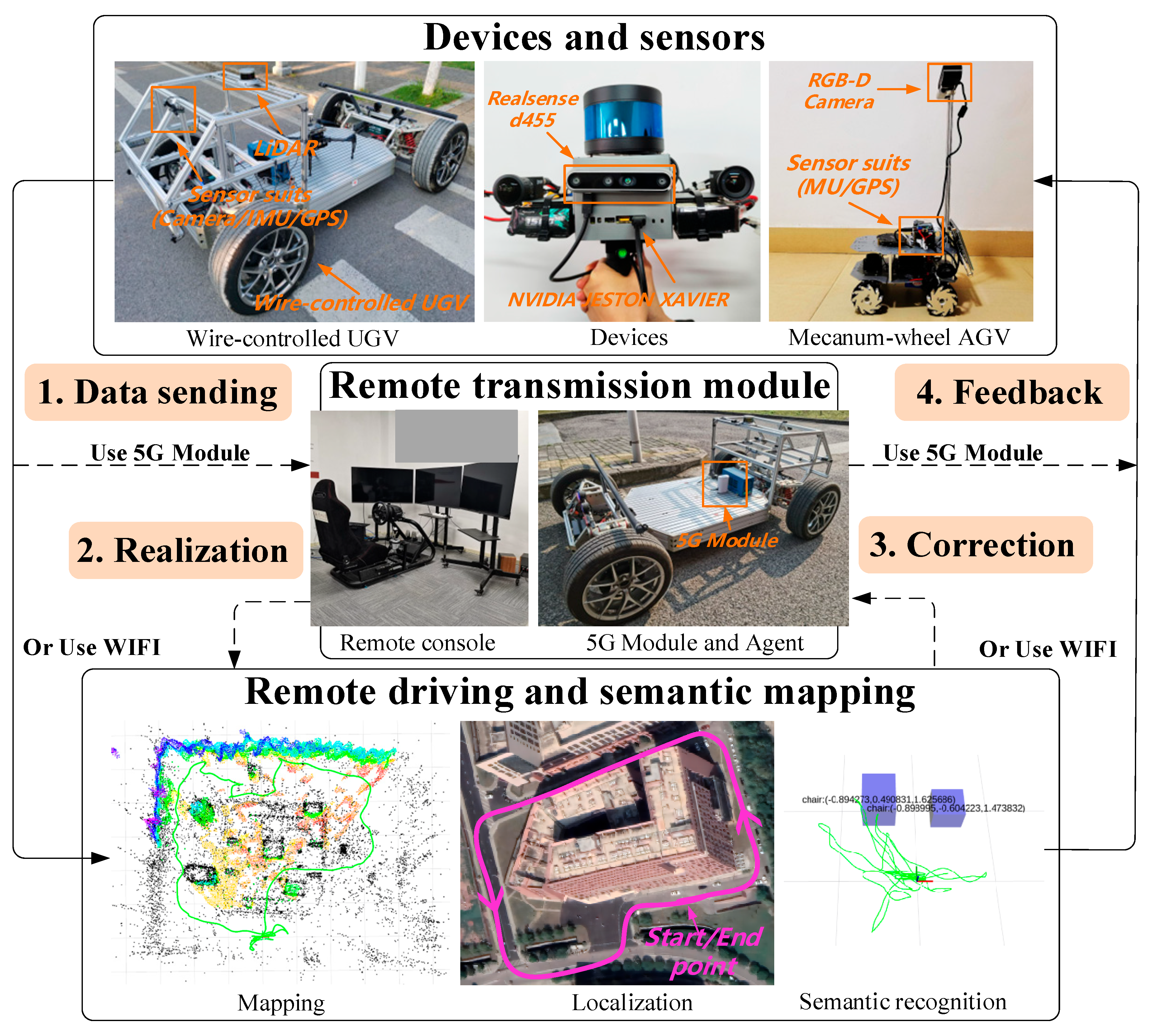
3. System Overview
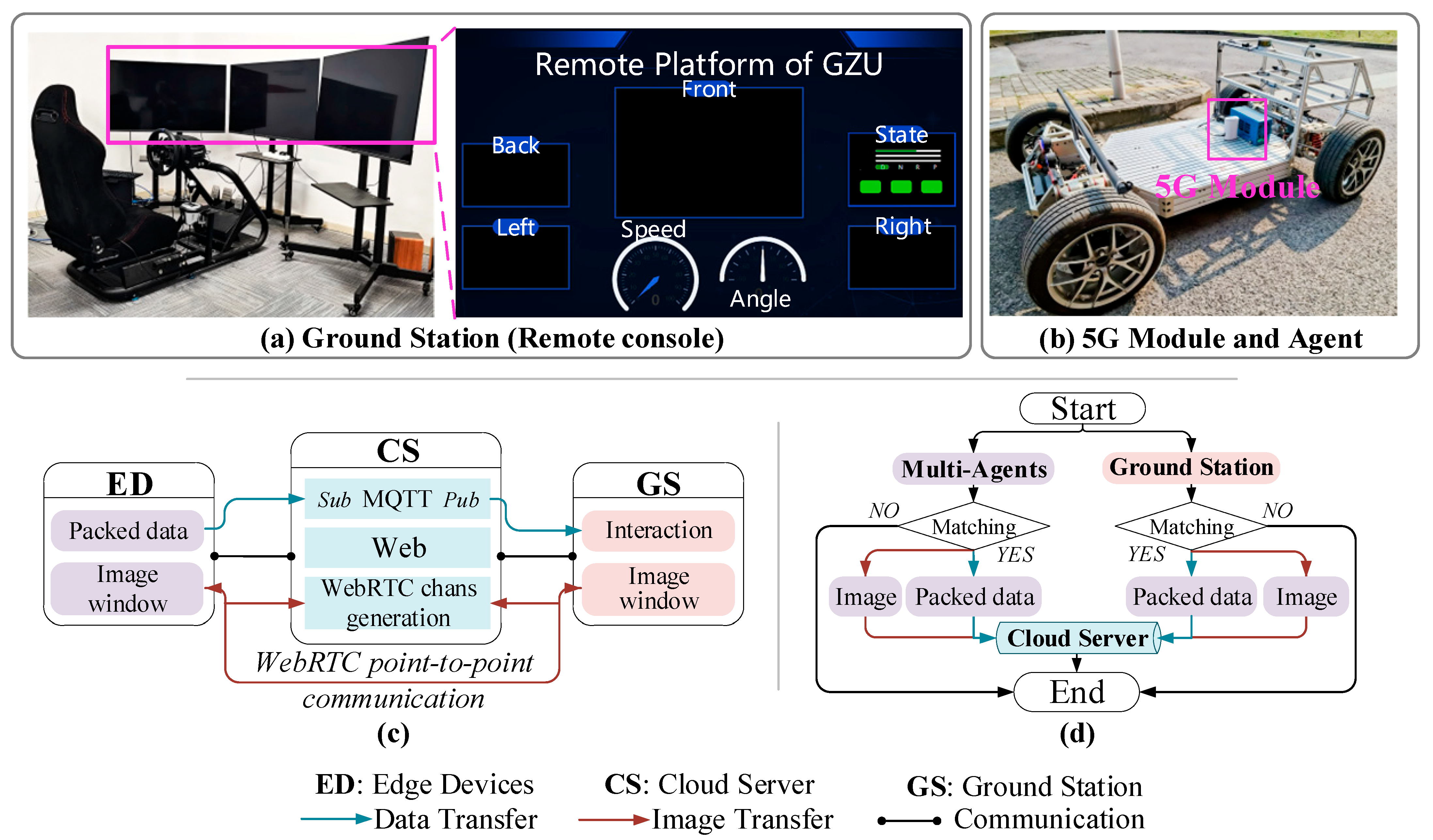
4. Remote Interaction
4.1. The Architecture of Remote Interaction
4.2. Performance Evaluation of Dual-Channel Communication
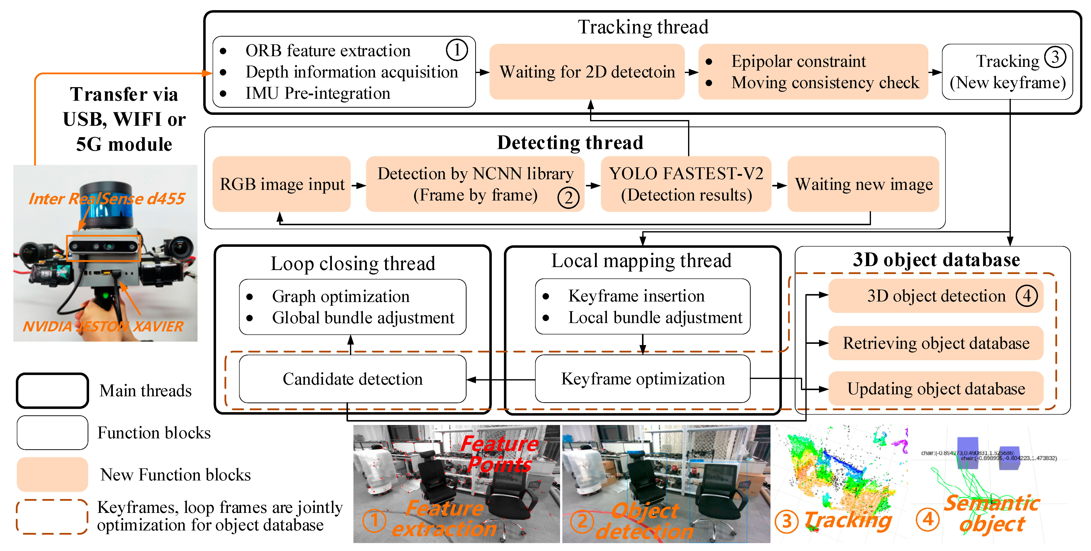
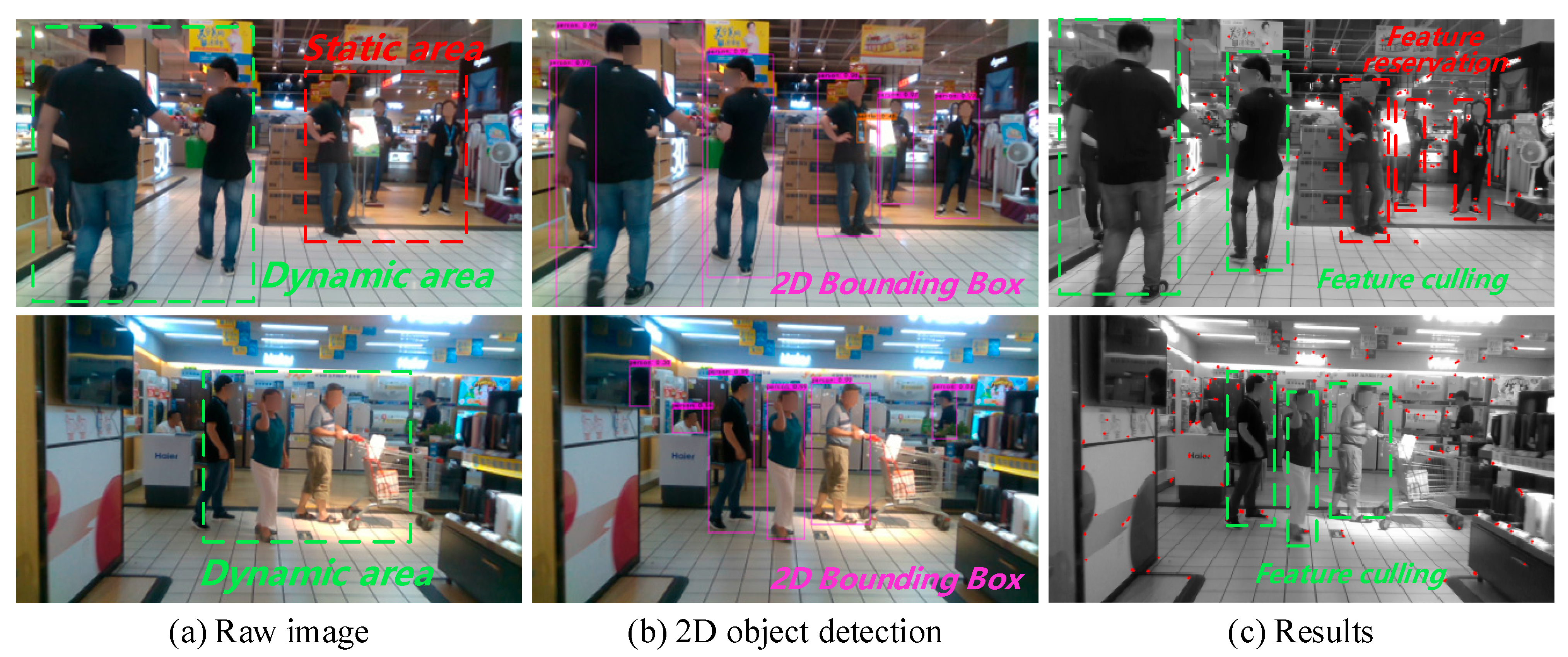
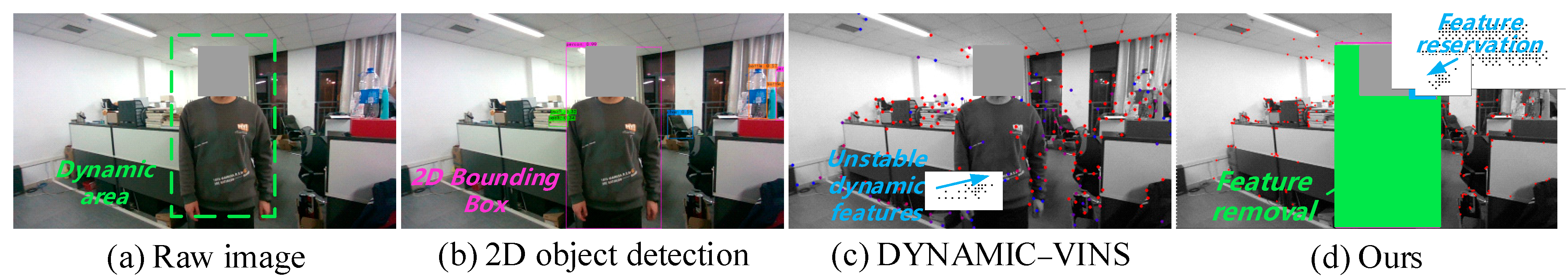
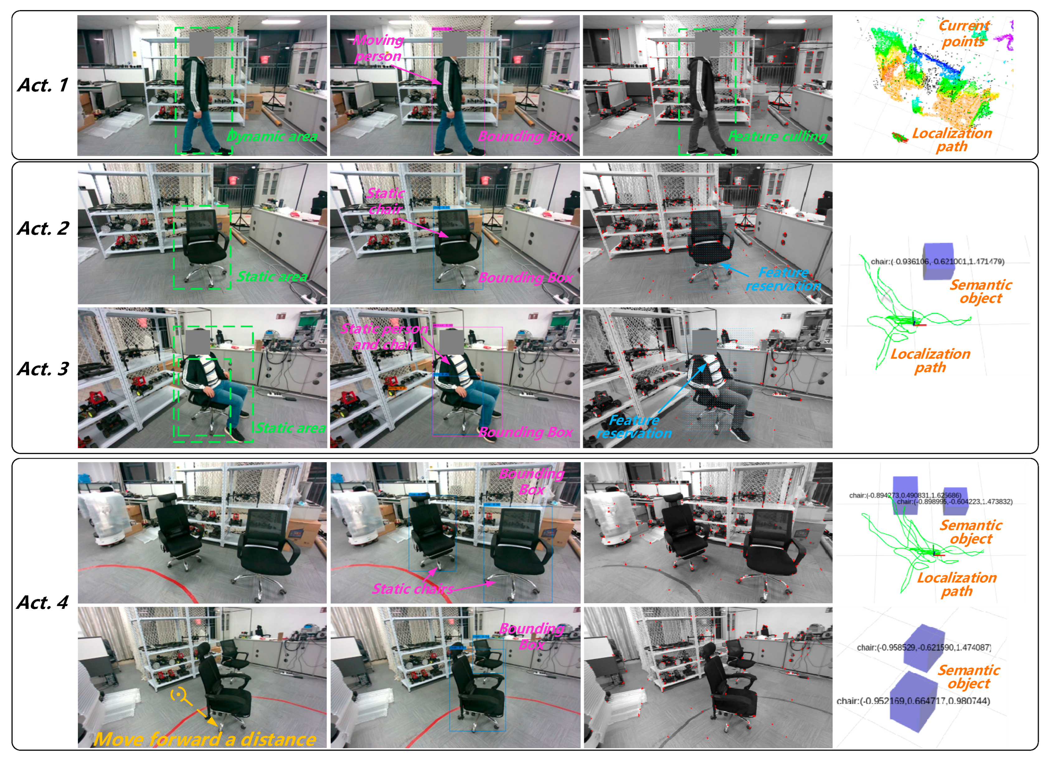
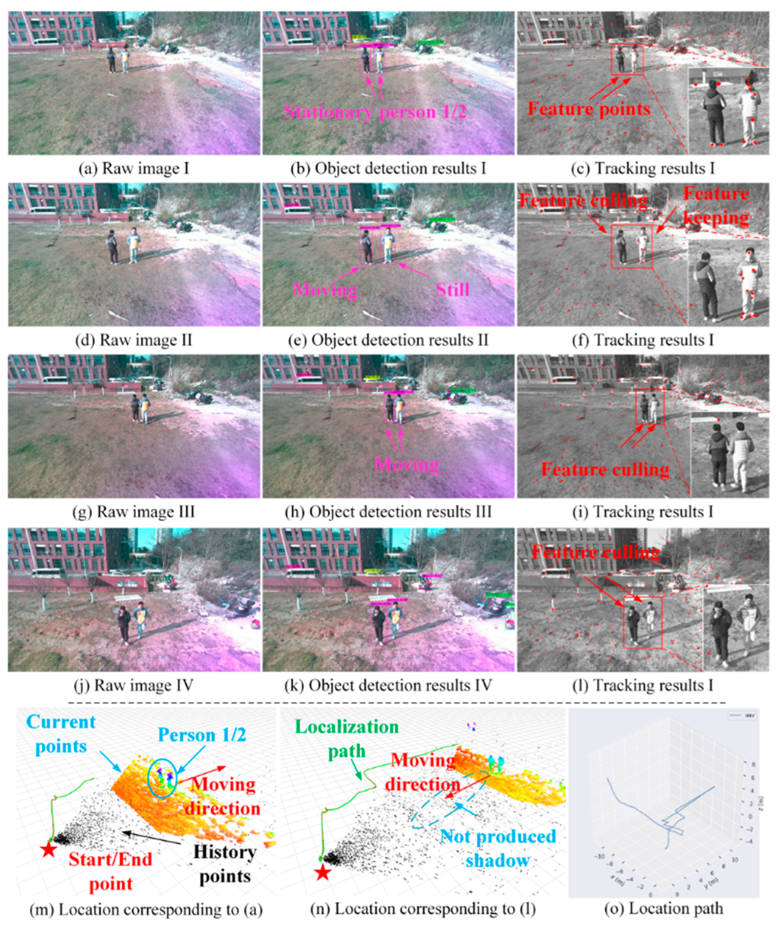
5. Dynamic Feature Removal Module
5.1. Selection of Object Detection Algorithm
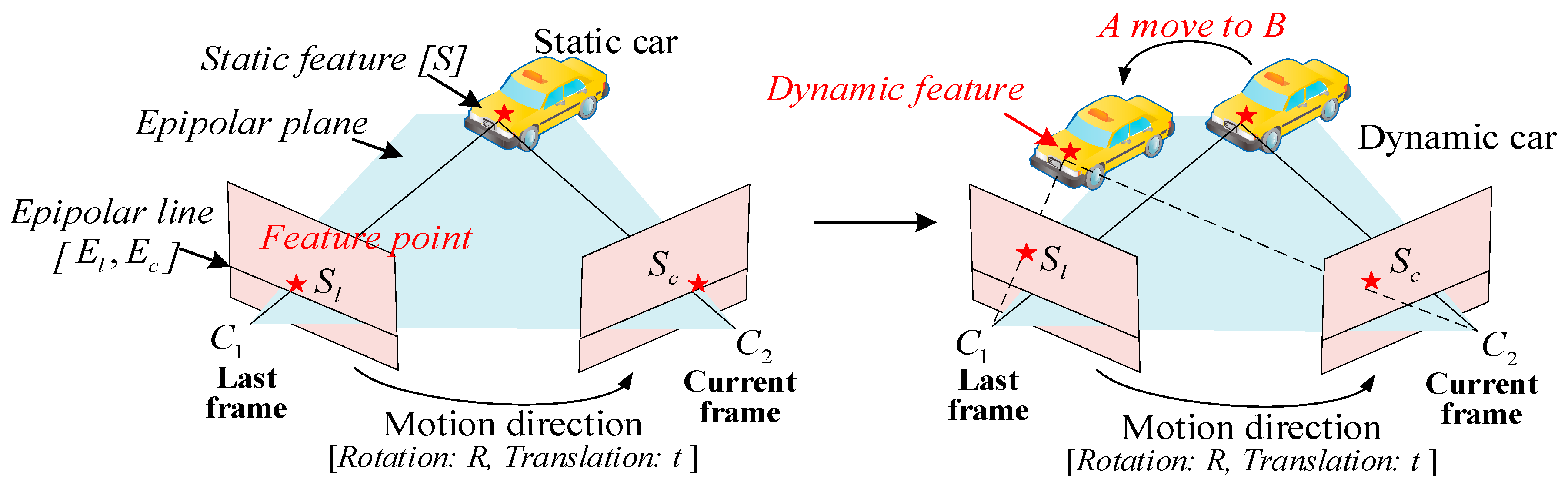
5.2. Epipolar Constraints for Removing Dynamic Points
| Algorithm 1 Epipolar constraints for removing dynamic points |
| Input: Last frame ; Current frame ; Features of last frame ; Features of current frame ; Output: The set of static features in current frame ; 1: = CalcOpticalFlowPyrLK (, , ) // LK flow to track in last frame 2: Filter the outliers in 3: FundMat = FindFundamentalMatrix (, , Iter-RANSAC) // Iter to calc the fundMat 4: for each matched feature , in , do: 5: if (ExistDynamicObjects && IsInBoundingBox ()) then 6: = FindEpipolarLine (, FundMat) // Calc epipolar line 7: = CalcEucliderDistanceFromEpipolarLine (, ) 8: if dist < th then 9: Append to 10: end if 11: end if 12: end for |
5.3. Moving Consistency Check for Rejecting Unstable Movements
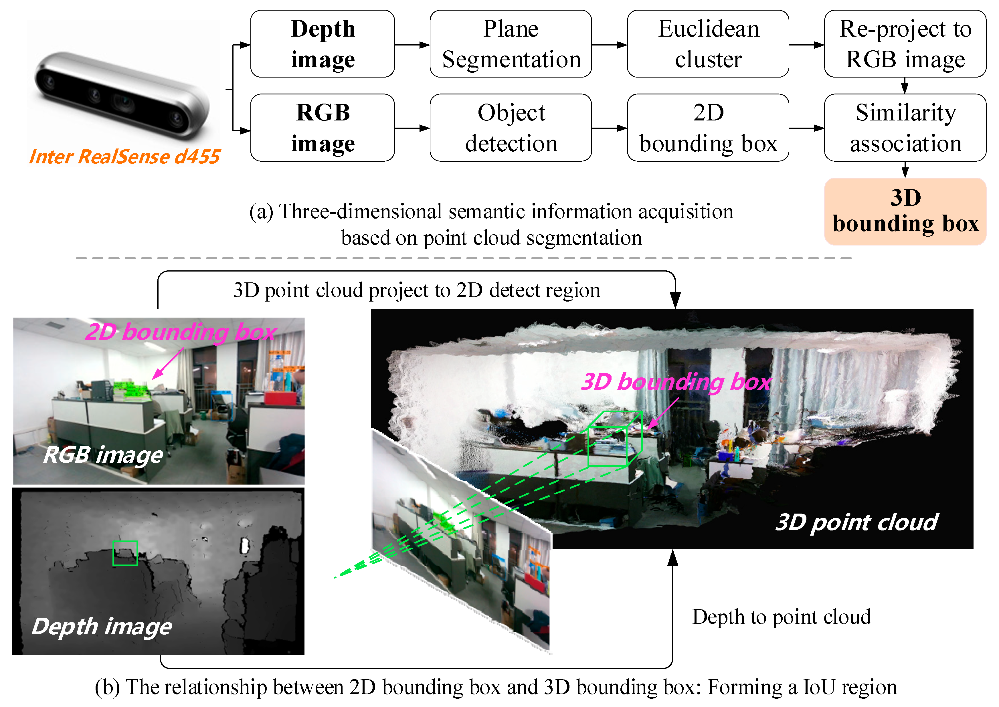
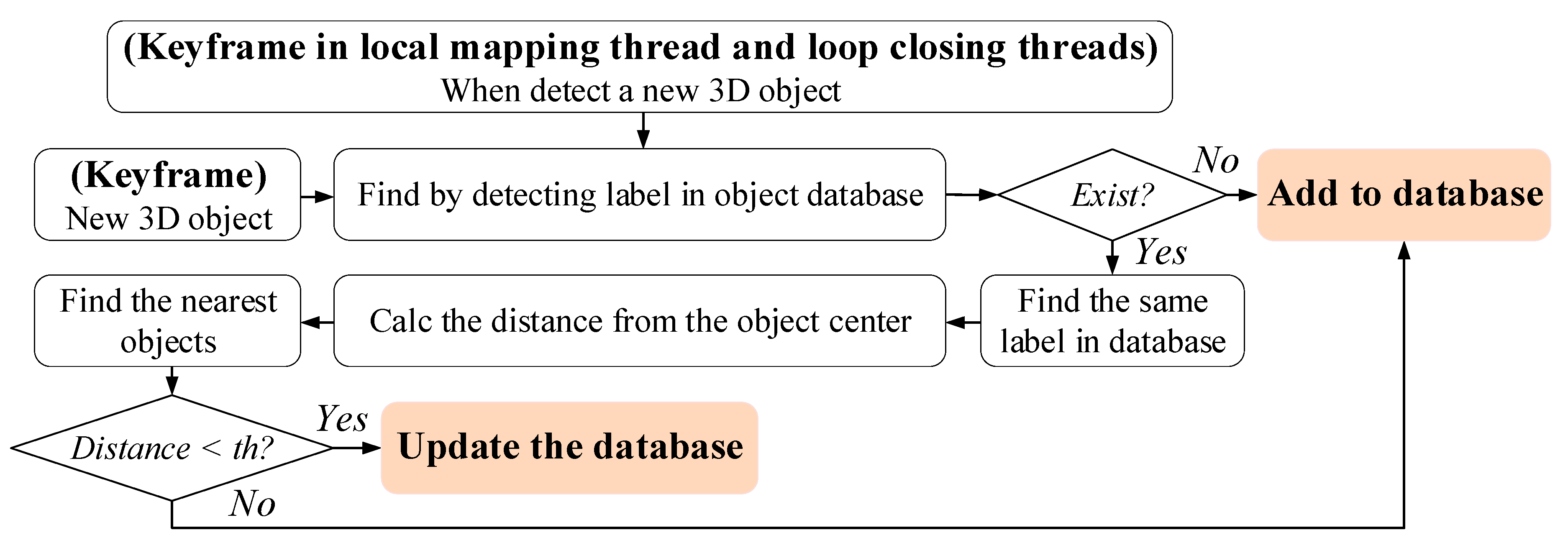
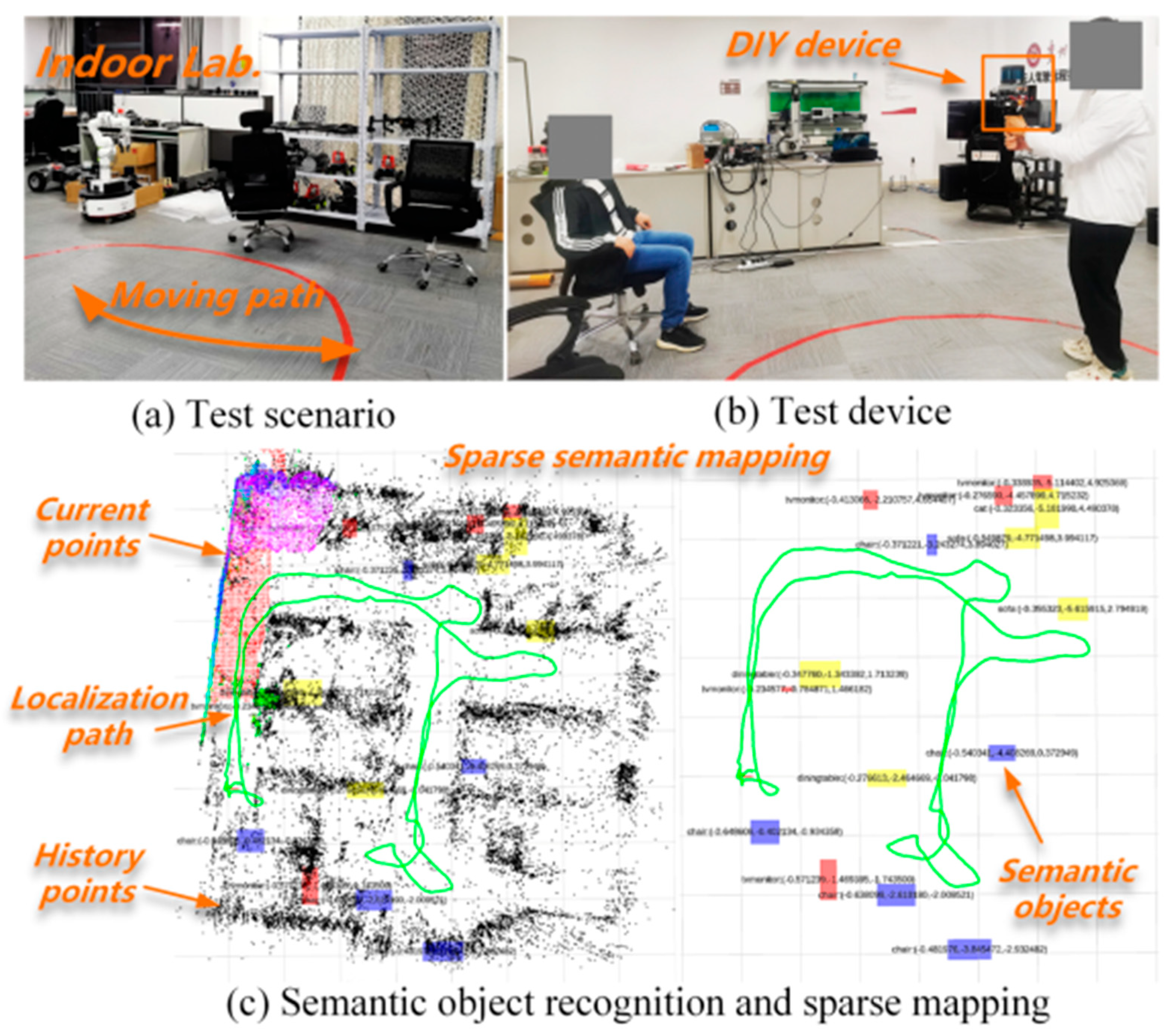
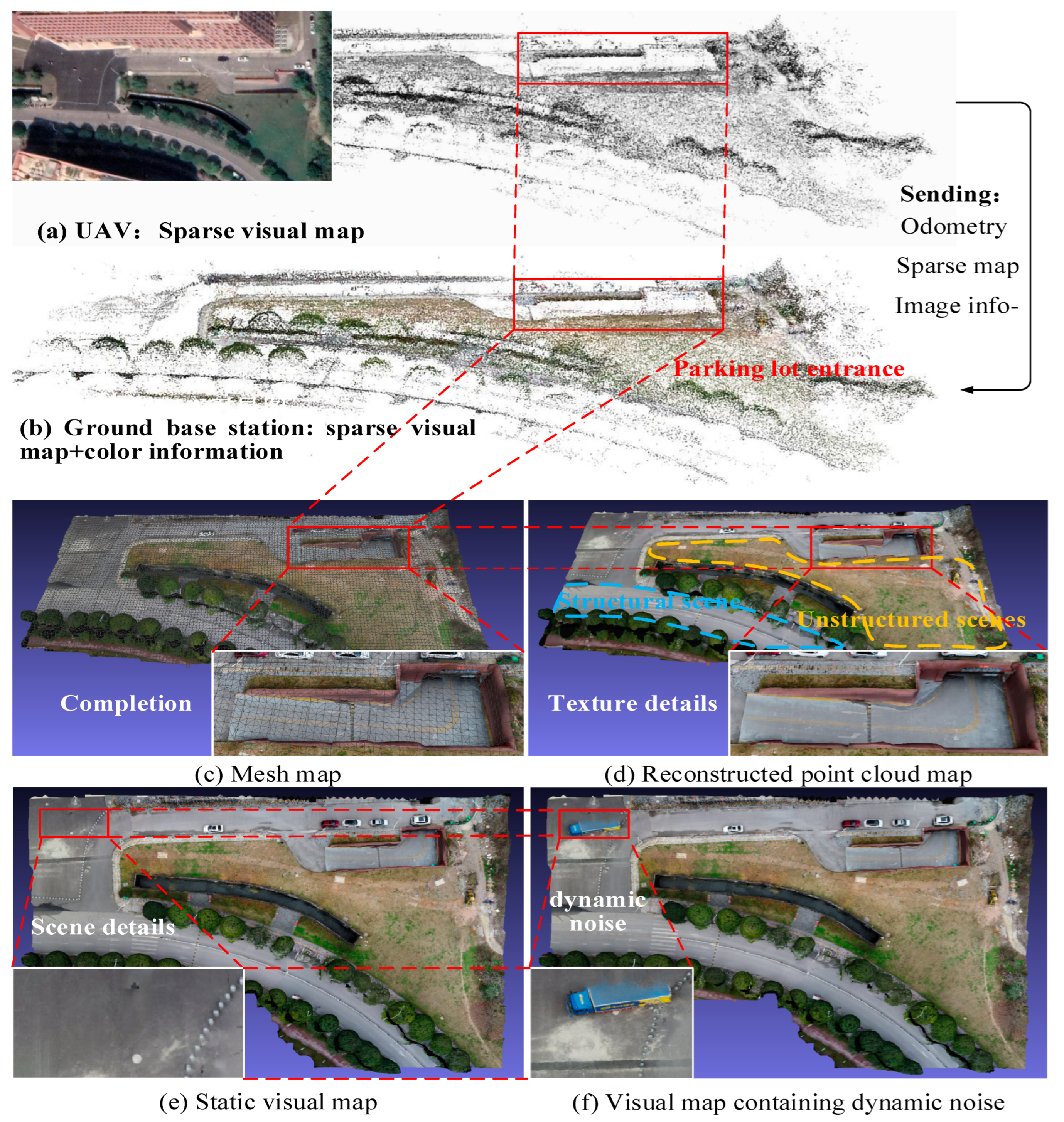
6. Semantic Object Database Construction
7. Results
7.1. Hardware Setup and Evaluation Metrics
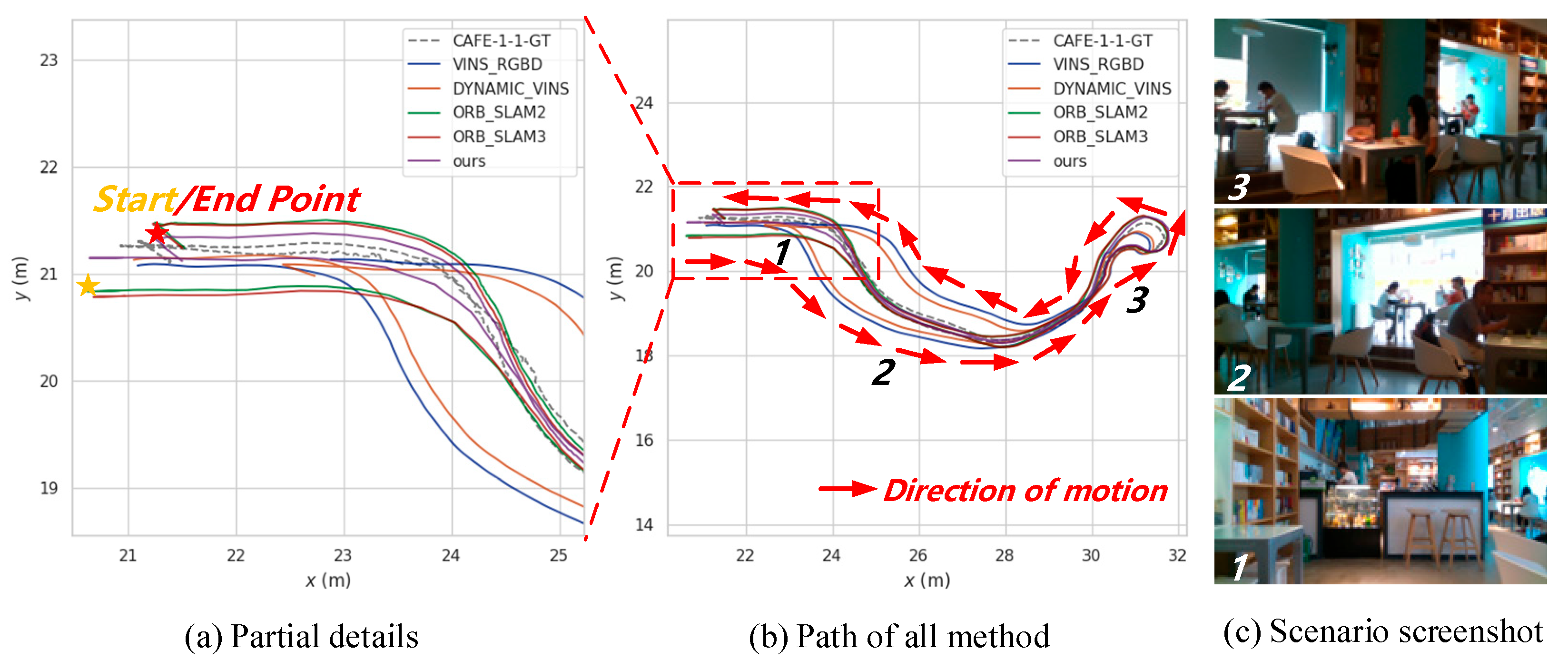
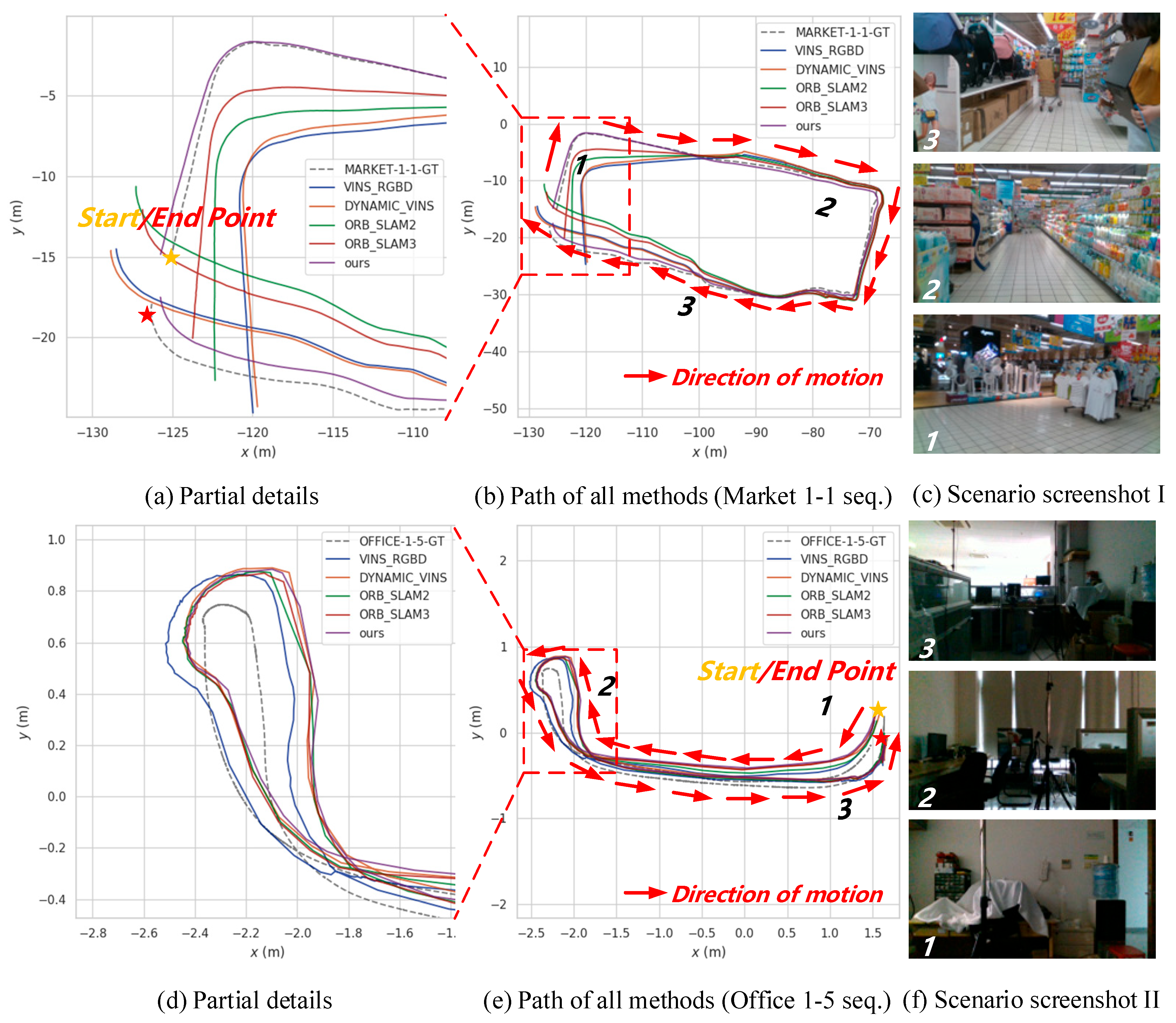
7.2. Simulation Datasets
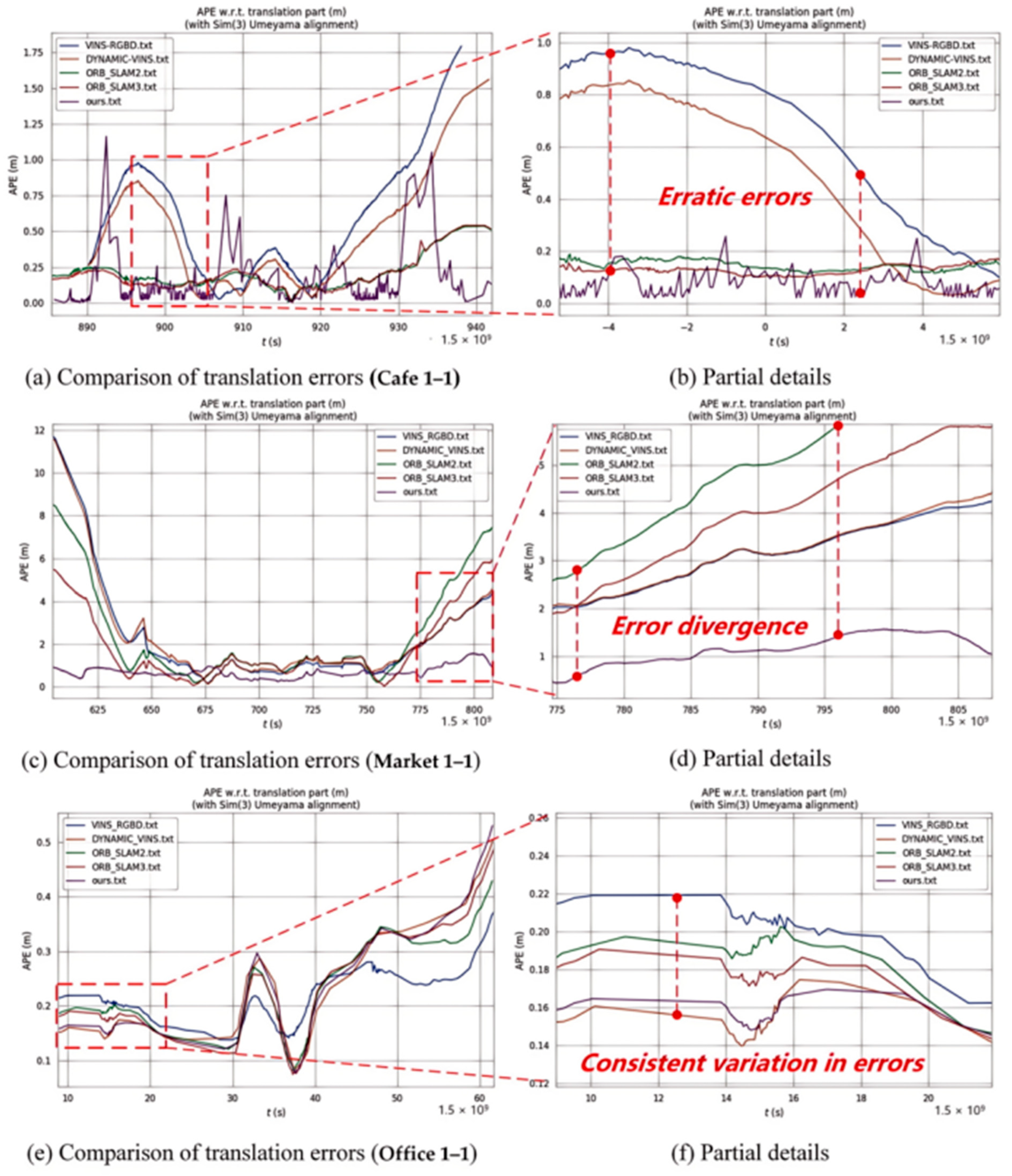
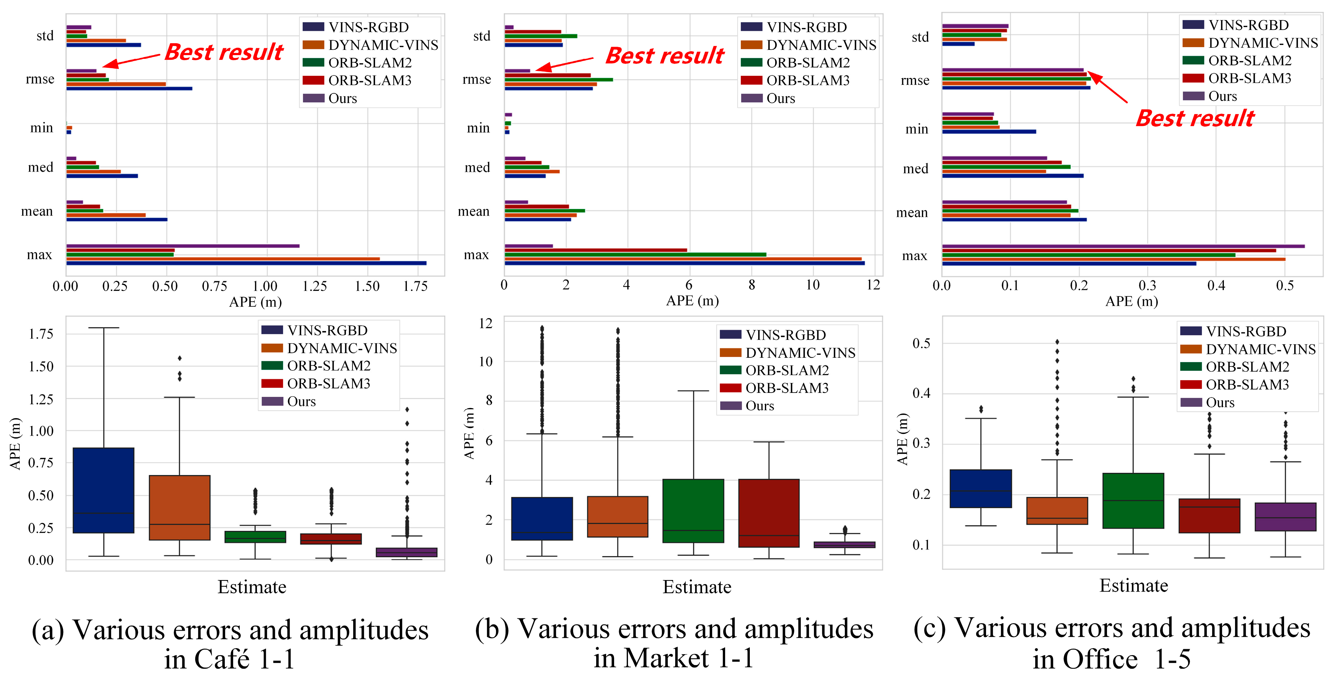
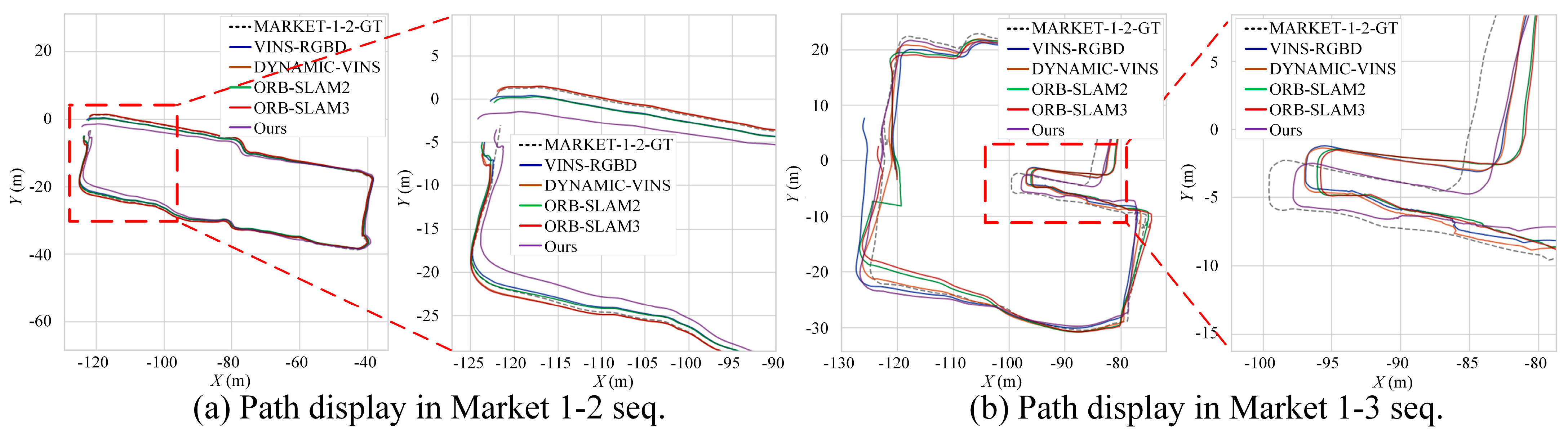
7.3. Localization Accuracy in OpenLORIS Benchmark
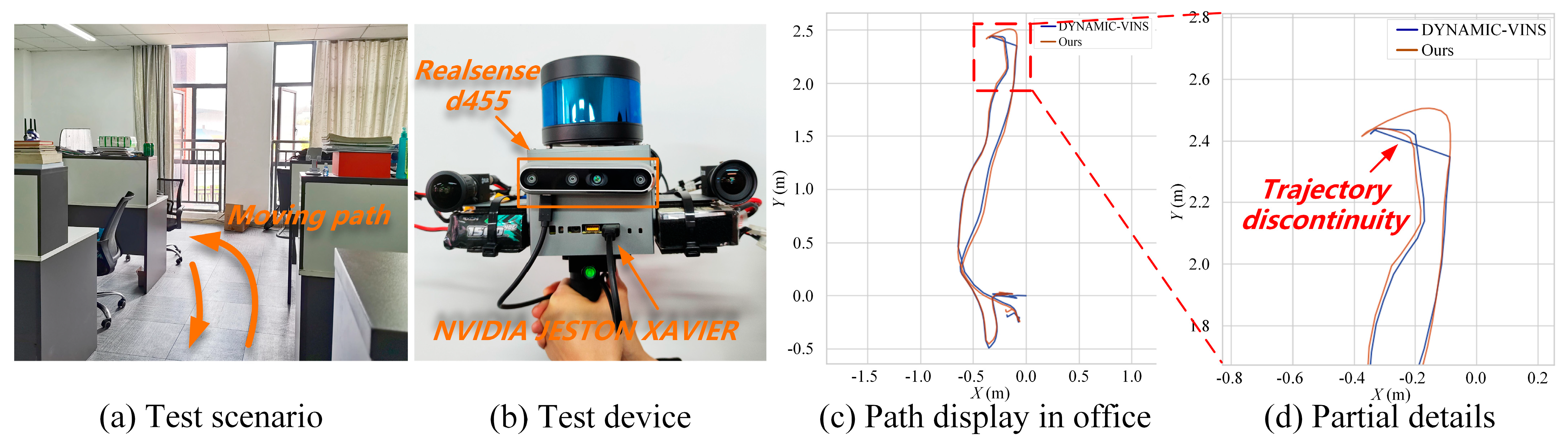
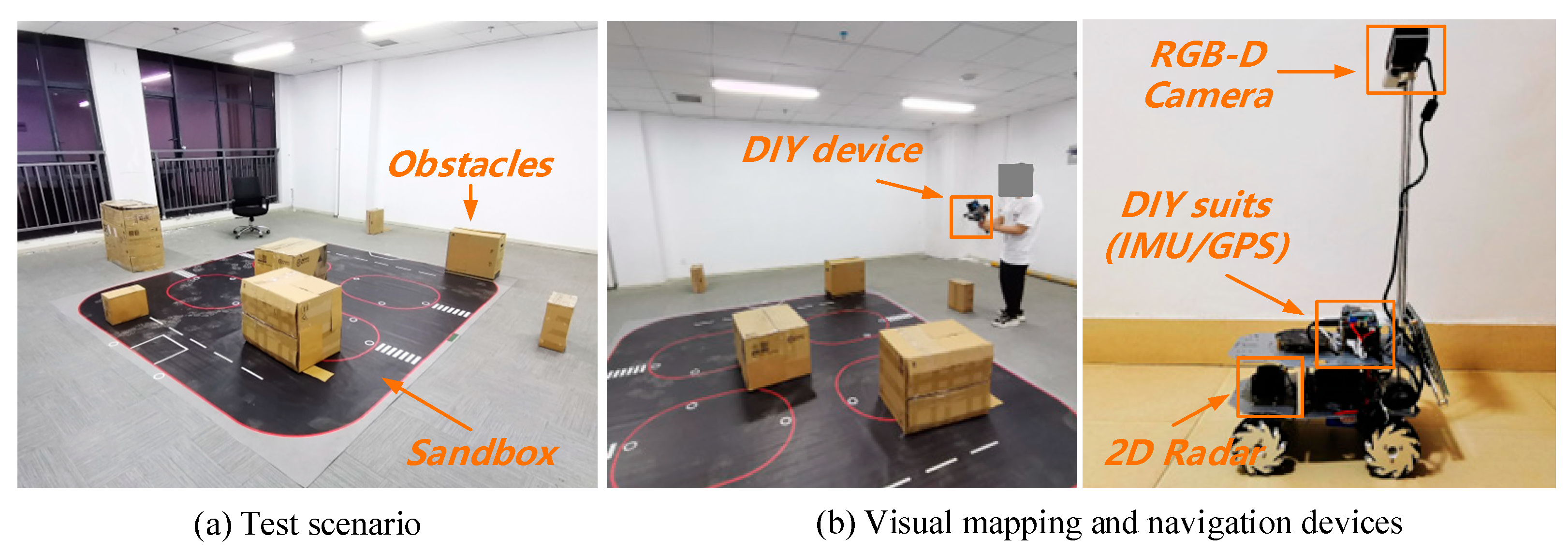
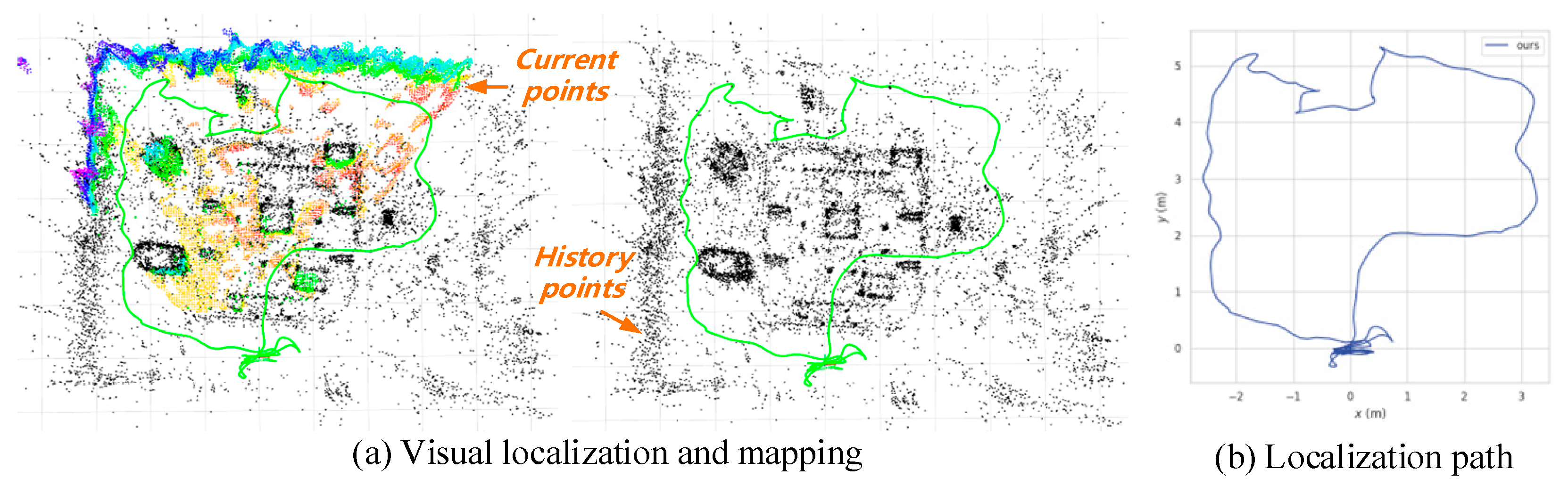
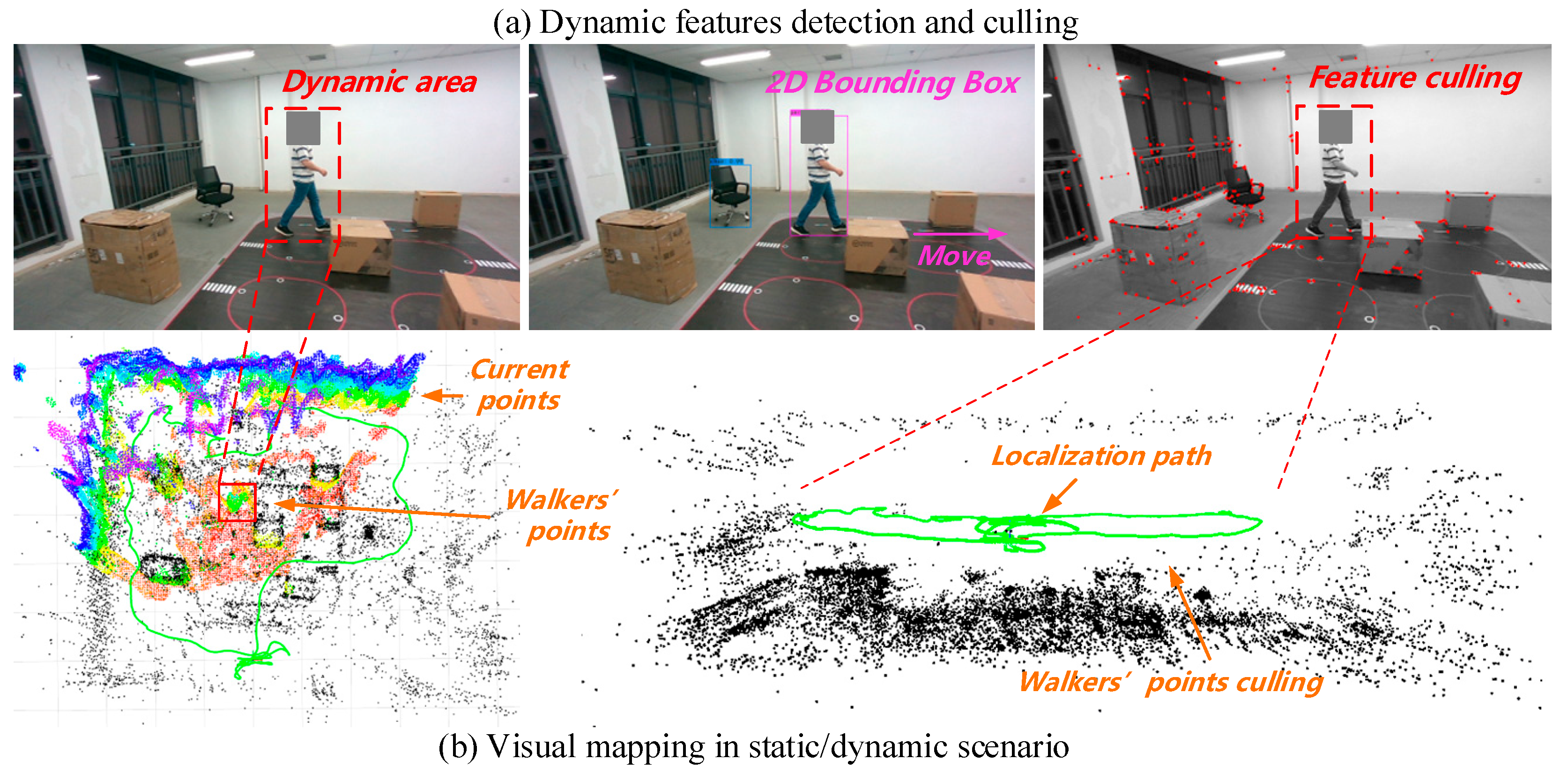
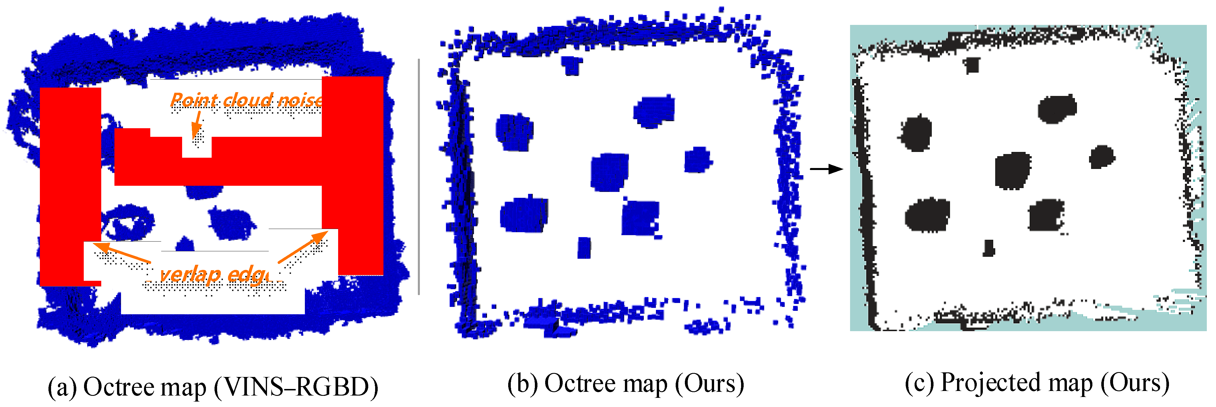
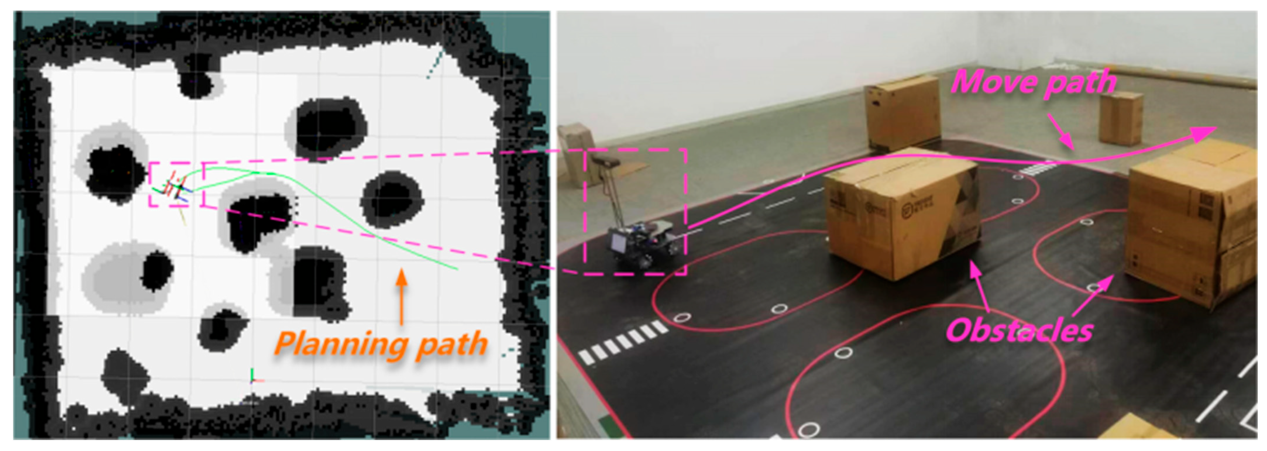
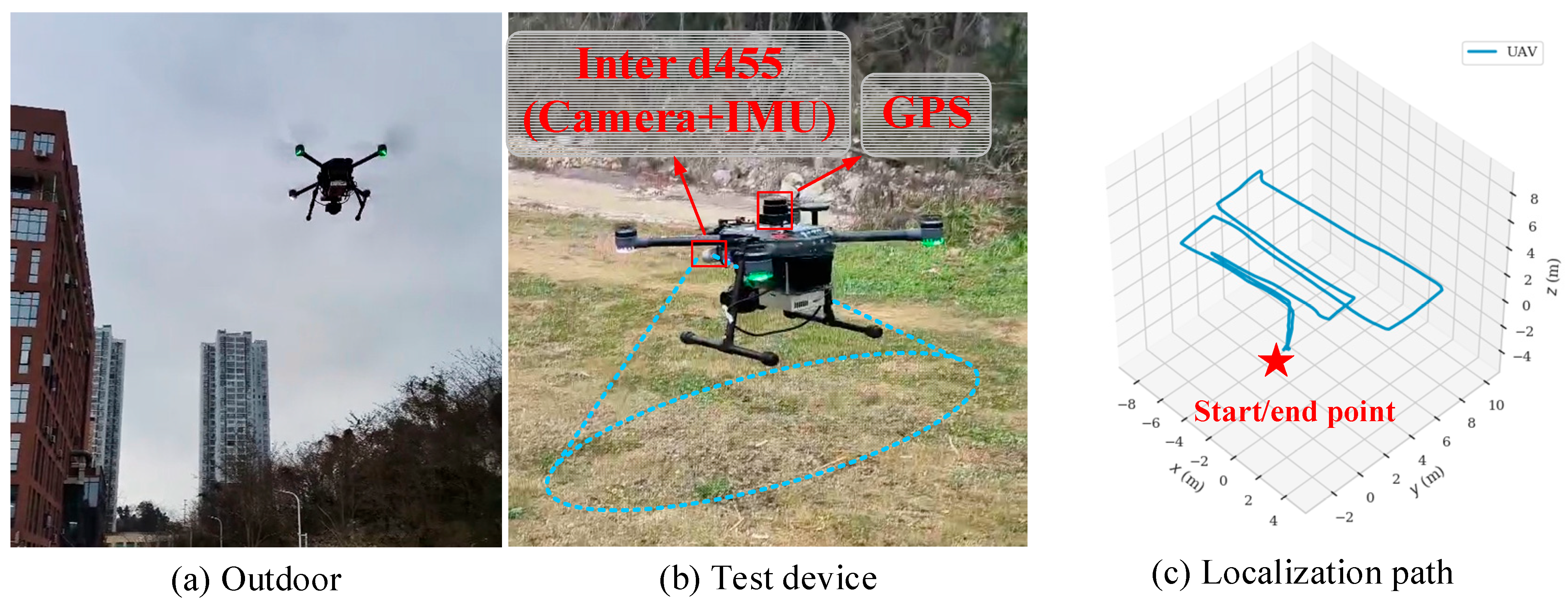
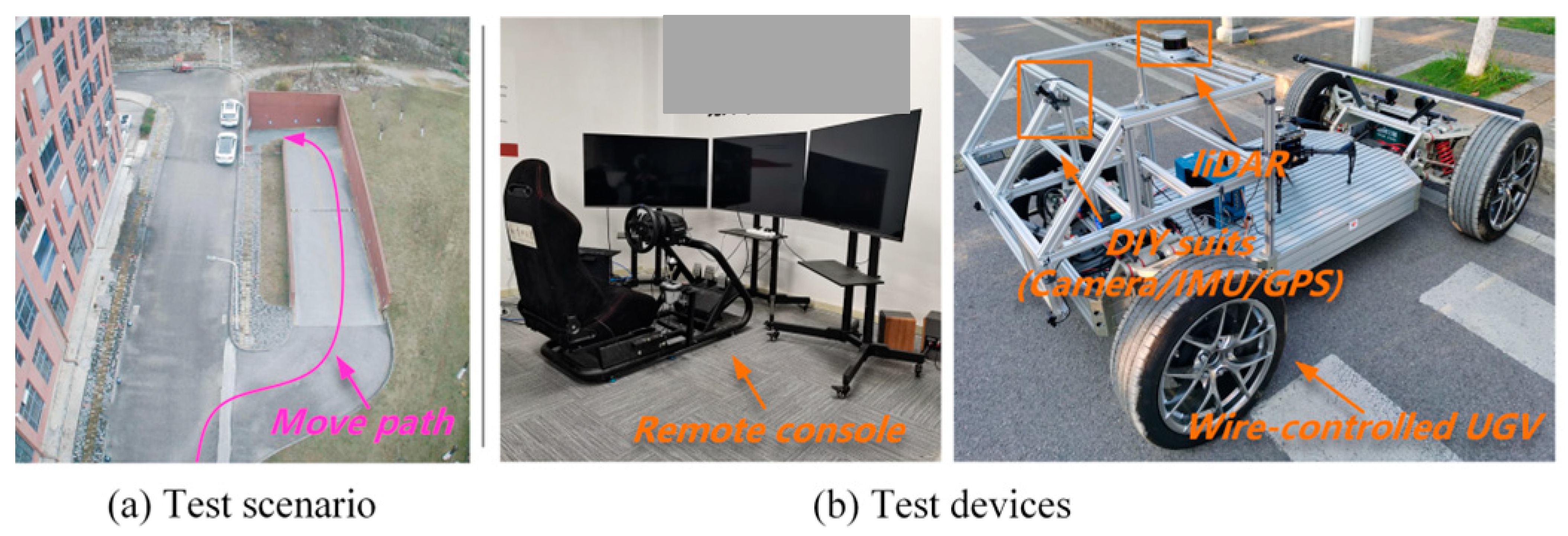
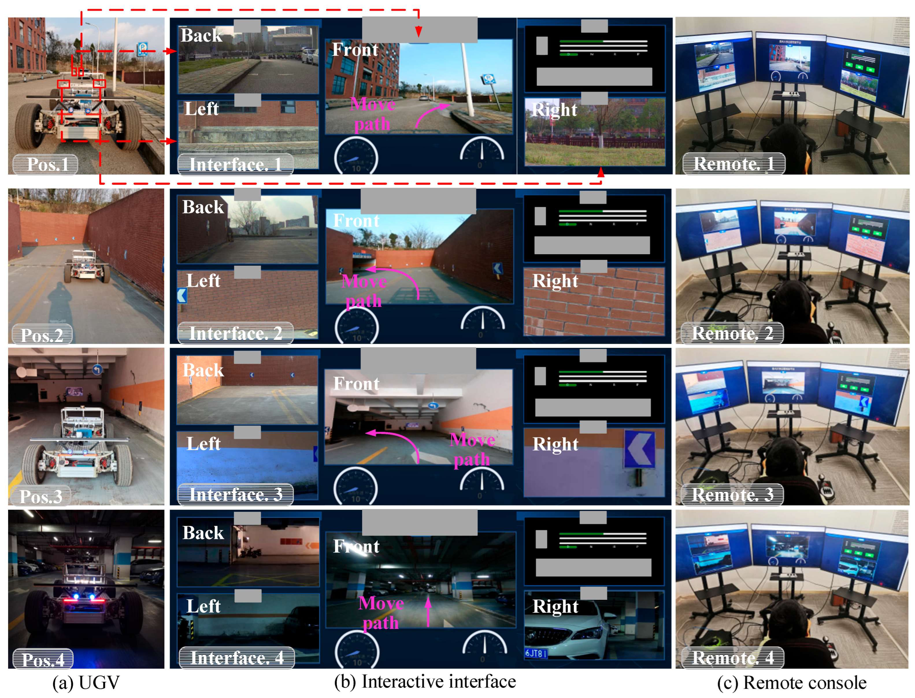
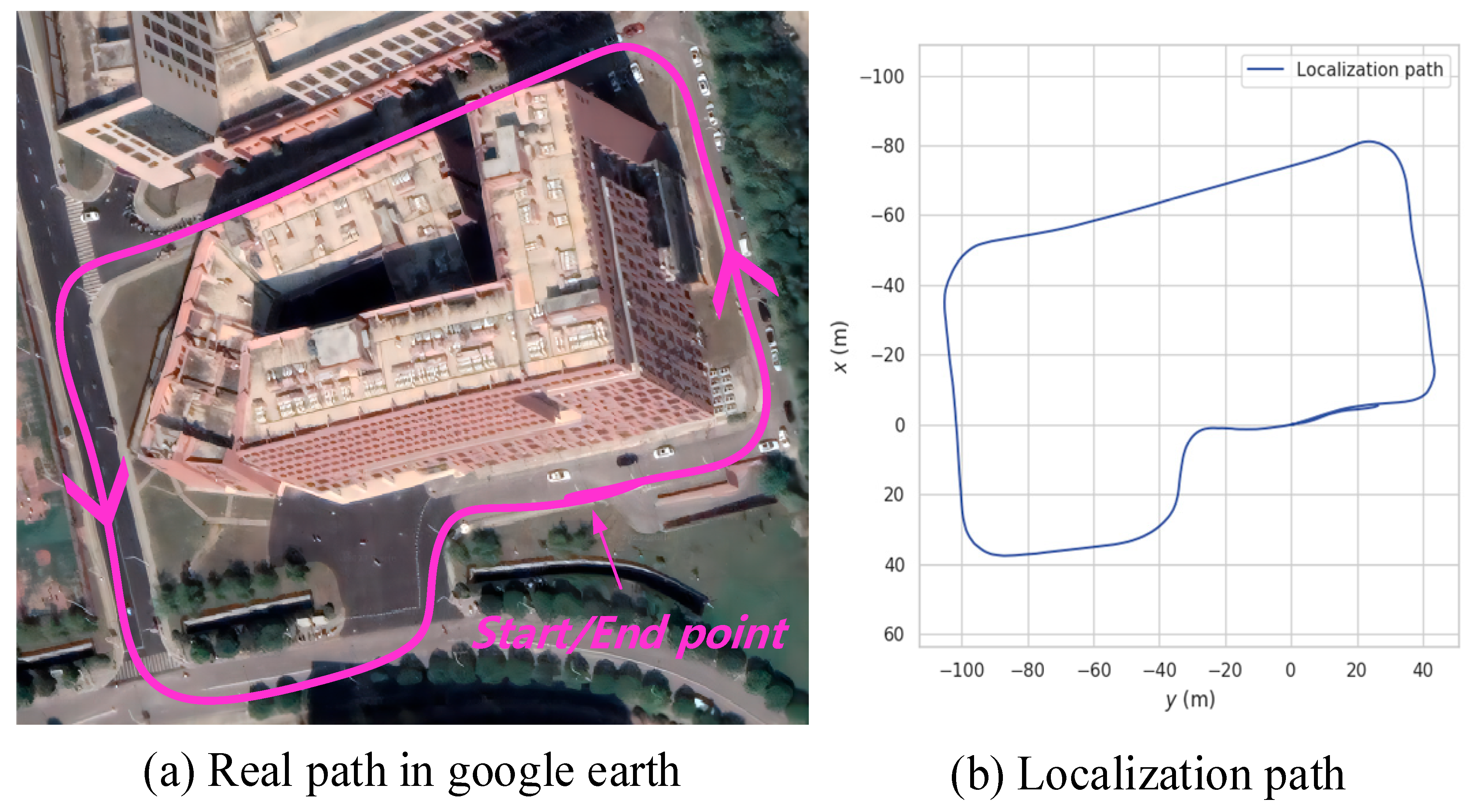
7.4. Real Scenario Test
8. Conclusions
Supplementary Materials
Author Contributions
Funding
Data Availability Statement
Acknowledgments
Conflicts of Interest
References
- Damjanović, D.; Biočić, P.; Prakljačić, S.; Činčurak, D.; Balen, J. A comprehensive survey on SLAM and machine learning approaches for indoor autonomous navigation of mobile robots. Mach. Vis. Appl. 2025, 36, 55. [Google Scholar] [CrossRef]
- Solanes, J.-E.; Gracia, L. Mobile Robots: Trajectory Analysis, Positioning and Control. Appl. Sci. 2025, 15, 355. [Google Scholar] [CrossRef]
- Liu, C.; Zhao, J.; Sun, N. A Review of Collaborative Air-Ground Robots Research. J. Intell. Robot. Syst. 2022, 106, 60. [Google Scholar] [CrossRef]
- Zheng, C.; Xu, W.; Zou, Z.; Hua, T.; Yuan, C.; He, D.; Zhang, F. Fast-livo2: Fast, direct lidar-inertial-visual odometry. IEEE Trans. Robot. 2024, 41, 329–346. [Google Scholar] [CrossRef]
- Fan, Y.; Zhang, Q.; Tang, Y.; Liu, S.; Han, H. Blitz-SLAM: A semantic SLAM in dynamic environments. Pattern Recognit. 2022, 121, 108225. [Google Scholar] [CrossRef]
- Campos, C.; Elvira, R.; Rodríguez, J.-J.-G.; Montiel, J.-M.; Tardós, J.-D. ORB-SLAM3: An accurate open-source library for visual, visual–inertial, and multimap slam. IEEE Trans. Robot. 2021, 37, 1874–1890. [Google Scholar] [CrossRef]
- Feng, D.; Haase, S.-C.; Rosenbaum, L.; Hertlein, H.; Glaeser, C.; Timm, F.; Dietmayer, K. Deep multi-modal object detection and semantic segmentation for autonomous driving: Datasets, methods, and challenges. IEEE Trans. Intell. Transp. Syst. 2020, 22, 1341–1360. [Google Scholar] [CrossRef]
- Sharafutdinov, D.; Griguletskii, M.; Kopanev, P.; Kurenkov, M.; Ferrer, G.; Burkov, A.; Tsetserukou, D. Comparison of modern open-source visual SLAM approaches. J. Intell. Robot. Syst. 2023, 107, 43. [Google Scholar] [CrossRef]
- Zhang, L.; Zhao, J.; Long, P.; Wang, L.; Qian, L.; Lu, F.; Manocha, D. An autonomous excavator system for material loading tasks. Sci. Robot. 2021, 6, eabc3164. [Google Scholar] [CrossRef]
- Le Dem, B.; Nakazawa, K. Exploiting the ACCuracy-ACCeleration tradeoff: VINS-assisted real-time object detection on moving systems. In Proceedings of the 2019 IEEE/ASME International Conference on Advanced Intelligent Mechatronics (AIM), Hong Kong, China, 8–12 July 2019; pp. 483–488. [Google Scholar]
- Bescos, B.; Fácil, J.M.; Civera, J.; Neira, J. DynaSLAM: Tracking, mapping, and inpainting in dynamic scenes. IEEE Robot. Autom. Lett. 2018, 3, 4076–4083. [Google Scholar] [CrossRef]
- Wen, S.; Li, P.; Zhao, Y.; Zhang, H.; Sun, F.; Wang, Z. Semantic visual SLAM in dynamic environment. Auton. Robot. 2021, 45, 493–504. [Google Scholar] [CrossRef]
- Yang, S.; Scherer, S. Cubeslam: Monocular 3-d object slam. IEEE Trans. Robot. 2019, 35, 925–938. [Google Scholar] [CrossRef]
- He, K.; Gkioxari, G.; Dollár, P.; Girshick, R. Mask r-cnn. In Proceedings of the IEEE International Conference on Computer Vision, Venice, Italy, 22–29 October 2017; pp. 2961–2969. [Google Scholar]
- Zhang, J.; Henein, M.; Mahony, R.; Ila, V. VDO-SLAM: A visual dynamic object-aware SLAM system. arXiv 2020, arXiv:2005.11052. [Google Scholar]
- Campos, C.; Montiel, J.-M.; Tardós, J.-D. Inertial-only optimization for visual-inertial initialization. In Proceedings of the 2020 IEEE International Conference on Robotics and Automation (ICRA), Virtual, 31 May–31 August 2020; pp. 51–57. [Google Scholar]
- Liu, J.; Li, X.; Liu, Y.; Chen, H. RGB-D Inertial Odometry for a Resource-Restricted Robot in Dynamic Environments. IEEE Robot. Autom. Lett. 2022, 7, 9573–9580. [Google Scholar] [CrossRef]
- Qin, T.; Li, P.; Shen, S. Vins-mono: A robust and versatile monocular visual-inertial state estimator. IEEE Trans. Robot. 2018, 34, 1004–1020. [Google Scholar] [CrossRef]
- Mur, A.-R.; Tardós, J.-D. Orb-slam2: An open-source slam system for monocular, stereo, and rgb-d cameras. IEEE Trans. Robot. 2017, 33, 1255–1262. [Google Scholar]
- Shan, Z.; Li, R.; Schwertfeger, S. RGBD-inertial trajectory estimation and mapping for ground robots. Sensors 2019, 19, 2251. [Google Scholar] [CrossRef]
- Chang, J.; Dong, N.; Li, D. A real-time dynamic object segmentation framework for SLAM system in dynamic scenes. IEEE Trans. Instrum. Meas. 2021, 70, 2513709. [Google Scholar] [CrossRef]
- Bolya, D.; Zhou, C.; Xiao, F.; Lee, Y.-J. Yolact: Real-time instance segmentation. In Proceedings of the IEEE/CVF International Conference on Computer Vision, Seoul, Republic of Korea, 27 October–2 November 2019; pp. 9157–9166. [Google Scholar]
- Cheng, S.; Sun, C.; Zhang, S.; Zhang, D. SG-SLAM: A Real-Time RGB-D Visual SLAM tow ards Dynamic Scenes with Semantic and Geometric Information. IEEE Trans. Instrum. Meas. 2022, 72, 1–12. [Google Scholar] [CrossRef]
- Zhao, Z.; He, C.; Zhao, G.; Zhou, J.; Hao, K. RA-YOLOX: Re-parameterization align decoupled head and novel label assignment scheme based on YOLOX. Pattern Recognit. 2023, 140, 109579. [Google Scholar] [CrossRef]
- Long, X.; Deng, K.; Wang, G.; Zhang, Y.; Dang, Q.; Gao, Y.; Wen, S. PP-YOLO: An effective and efficient implementation of object detector. arXiv 2020, arXiv:2007.12099. [Google Scholar]
- Liu, W.; Anguelov, D.; Erhan, D.; Szegedy, C.; Reed, S.; Fu, C.-Y.; Berg, A.-C. Ssd: Single shot multibox detector. In Computer Vision–ECCV 2016, Proceedings of the 14th European Conference, Amsterdam, The Netherlands, 11–14 October 2016; Part I 14; Springer International Publishing: Cham, Switzerland, 2016; pp. 21–37. [Google Scholar]
- Sato, Y.; Kashihara, S.; Ogishi, T. Robust Video Transmission System Using 5G/4G Networks for Remote Driving. In Proceedings of the 2022 IEEE Intelligent Vehicles Symposium (IV), Aachen, Germany, 4–9 June 2022; pp. 616–622. [Google Scholar]
- Hetzer, D.; Muehleisen, M.; Kousaridas, A.; Alonso-Zarate, J. 5G Connected and Automated Driving: Use Cases and Technologies in Cross-Border Environments. In Proceedings of the IEEE European Conference on Networks and Communications (EuCNC), Valencia, Spain, 18–21 June 2019; pp. 78–82. [Google Scholar]
- Dhakal, A.; Ran, X.; Wang, Y.; Chen, J.; Ramakrishnan, K.-K. SLAM-share: Visual simultaneous localization and mapping for real-time multi-user augmented reality. In Proceedings of the 18th International Conference on Emerging Networking EXperiments and Technologies, Rome, Italy, 6–9 December 2022; pp. 293–306. [Google Scholar]
- Tencent. NCNN. [Online]. 2017. Available online: https://github.com/Tencent/ncnn (accessed on 1 May 2024).
- Cheng, J.; Zhang, L.; Chen, Q.; Hu, X.; Cai, J. A review of visual SLAM methods for autonomous driving vehicles. Eng. Appl. Artif. Intell. 2022, 114, 104992. [Google Scholar] [CrossRef]
- Hartley, R.; Zisserman, A. Multiple View Geometry in Computer Vision; Cambridge University Press: Cambridge, UK, 2004. [Google Scholar]
- Fischler, M.A.; Bolles, R.C. Random Sample Consensus: A Paradigm for Model Fitting with Applications to Image Analysis and Automated Cartography. Commun. ACM 1981, 24, 381–395. [Google Scholar] [CrossRef]
- Lucas, B.D.; Kanade, T. An Iterative Image Registration Technique with an Application to Stereo Vision. In Proceedings of the IJCAI, Vancouver, BC, Canada, 24–28 August 1981; pp. 674–679. [Google Scholar]
- Bouguet, J.Y. Pyramidal Implementation of the Lucas-Kanade Feature Tracker cve-99-01; Intel Corporation Tech. Rep.: Santa Clara, CA, USA, 1999; pp. 1–10. [Google Scholar]
- Shi, X.; Li, D.; Zhao, P.; Tian, Q.; Tian, Y.; Long, Q.; She, Q. Are we ready for service robots? The openloris-scene datasets for lifelong slam. In Proceedings of the 2020 IEEE International Conference on Robotics and Automation (ICRA), Virtual, 31 May–31 August 2022; pp. 3139–3145. [Google Scholar]
- Mur, A.-R.; Montiel, J.M.M.; Tardos, J.-D. ORB-SLAM: A versatile and accurate monocular SLAM system. IEEE Trans. Robot. 2015, 31, 1147–1163. [Google Scholar]

| Method | Dynamic Feature Culling | Processing Speed | Model Size/Power | Advs. | Dis-Advs. |
|---|---|---|---|---|---|
| Dyna- SLAM | Instance segmentation (Mask R-CNN) | 5-7 FPS (Jetson TX2) | 45 MB model size | High dynamic feature rejection | Low FPS unsuitable for UAV real-time requirements |
| Dynamic- VINS | YOLOv3-based detection | 15 FPS (Xavier) | 32 MB, 5 W power consumption | Lightweight for embedded systems | Incomplete semantic mapping in occlusions |
| YOLACT- SLAM | Real-time instance segmentation (YOLACT) | 23 FPS (Xavier) | 28 MB, 7 W | Balances speed and segmentation precision | Sacrifices mIoU (72.4%) for speed |
| SG-SLAM | SSD detection + geometric constraints | 30 FPS (Nano) | 25 MB, 4 W | 30% faster loop closure than baseline | Limited dynamic feature rejection |
| Cube SLAM | Multi-view cuboid proposals (no DL) | 12 FPS (CPU-only) | Lightweight (no GPU needed) | Geometry-based, no deep learning dependency | Fails in dynamic scenes |
| VDO- SLAM | Optical flow + detection fusion | 10 FPS (High-power GPU) | 8 W power consumption | High tracking consistency (89%) | Incompatible with micro-UAV power budgets (5 W max) |
| Ours | YOLO-FASTEST + epipolar constraints | 75 FPS (Xavier) | 21 MB, 10 W (UAV-optimized) | Real-time hybrid filtering, low-latency comm. | Requires semantic-geometric calibration |
| Component | Device/Model | Key Specifications | Role |
|---|---|---|---|
| Edge Devices (EDs) | NVIDIA Jetson AGX Xavier (UAVs) | 8 GB HBM2, 3.3 GHz Hexa-core ARM, RealSense D455 (RGB-D + IMU), 5G/Wi-Fi module | On-board SLAM, object detection, sensor data preprocessing |
| NVIDIA Jetson Nano (UGVs) | 4 GB LPDDR4, 1.43 GHz Quad-core ARM, RealSense D455/LiDAR, Wi-Fi adapter | Low-power localization, telemetry aggregation | |
| Ground Station (GS) | Intel Core i5-9300H Laptop | 16 GB RAM, 5G/Wi-Fi connectivity | Human-in-the-loop control, real-time visualization |
| Cloud Server (CS) | Tencent Cloud Instance | 50 Mbps bandwidth, regional data center hosting | Multi-agent coordination, semantic map synchronization |
| Sensors | Intel RealSense D455 | 1080p RGB, 1280 × 720 depth, 200 Hz IMU, hardware-synchronized timestamping (<10 μs drift) | Environmental perception (RGB-D, inertial data) |
| Detector | Inference Speed (FPS) | mAP@0.5 (%) | Model Size (MB) | Quantized mAP@0.5 (%) |
|---|---|---|---|---|
| YOLO—FASTEST | 75 | 58.2 | 21 | 56.8 * |
| YOLOX—Nano | 62 | 61.5 | 32 | N/A |
| PP—YOLO Tiny | 55 | 56.8 | 28 | N/A |
| MobileNet—SSD | 45 | 52.3 | 25 | N/A |
| Module Pair | Mean Timestamp Drift | Max Allowed Drift | Compensation Method |
|---|---|---|---|
| RGB–IMU | <10 μs | 20 μs | Hardware clock synchronization |
| Detection–RGB | 32 ms (median) | 50 ms | Sliding window with nearest-neighbor matching |
| Mapping–Detection | 18 ms (processing delay) | - | IMU-based pose extrapolation |
| Datasets | Environment | Device | Type | View |
|---|---|---|---|---|
| Cafe (1_1-1_2) | Indoor | Mobile Robot (Camera and IMU) | (Simulations) RGB and depth and acceleration/angular velocity | Front |
| Market (1_1-1_3) | ||||
| Office (1_1-1_7) |
| State | Systems | VINS–RGBD | DYNAMIC–VINS | ORB–SLAM2 | ORB–SLAM3 | Ours | |
|---|---|---|---|---|---|---|---|
| Datasets | |||||||
| Dynamic | Cafe 1-1 | 0.6302 | 0.6011 | 0.2146 | 0.1978 | 0.1275 | |
| Cafe 1-2 | 0.3075 | 0.2533 | 0.4041 | 0.2738 | 0.2719 | ||
| Market 1-1 | 2.8768 | 0.7033 | 2.9927 | 2.2297 | 0.5788 | ||
| Market 1-2 | 1.0674 | 1.0459 | 1.1951 | 1.2646 | 2.1437 | ||
| Market 1-3 | 2.4590 | 2.2505 | 3.6108 | 3.7318 | 1.8559 | ||
| Static | Office 1-1 | 0.0619 | 0.0613 | 0.0792 | 0.0544 | 0.0530 | |
| Office 1-2 | 0.2139 | 0.2115 | 0.2228 | 0.1293 | 0.1271 | ||
| Office 1-3 | 0.0441 | 0.0433 | 0.0517 | 0.0319 | 0.0455 | ||
| Office 1-4 | 0.0873 | 0.0898 | 0.1012 | 0.0847 | 0.0851 | ||
| Office 1-5 | 0.2171 | 0.2108 | 0.2178 | 0.2116 | 0.2075 | ||
| Office 1-6 | 0.0994 | 0.0871 | 0.1015 | 0.0933 | 0.0930 | ||
| Office 1-7 | 0.1015 | 0.1158 | 0.2025 | 0.1219 | 0.1744 | ||
| Scenario | Dynamic Feature Removal Rate (%) | Localization RMSE (m) |
|---|---|---|
| Perfect Detection (all classes) | 91.3 | 0.152 (EuRoC V1_03) |
| Unclassified Moving Objects | 82.0 | 0.189 (vs. 0.245 for geometric-only) |
| 20% Detection Errors (false negatives) | 76.5 | 0.178 (18% increase but 27% better than baseline) |
| Dataset | Seq | Scenario Characteristics | Ours (m) | ORB–SLAM3 (m) | Dynamic–VINS (m) | VINS–RGBD (m) |
|---|---|---|---|---|---|---|
| EuRoC MAV | V1_03_difficult | Fast motion + dynamic humans | 0.152 | 0.148 | 0.211 | 0.245 |
| V2_03_difficult | High-speed flight + clutter | 0.168 | 0.175 | 0.205 | 0.232 | |
| TUM–VI | room1 | Static + occasional motion | 0.112 | 0.135 | 0.127 | 0.168 |
| room2 | Semi-dynamic + rotating objects | 0.135 | 0.158 | 0.159 | 0.187 | |
| corridor | Low light + feature sparsity | 0.189 | 0.210 | 0.223 | 0.251 |
| Datasets | Time | Path | Environment | Type | View |
|---|---|---|---|---|---|
| S1 | 28.30 s | 8.93 m | Office and indoor | (Real scenario) Raw image and acceleration/angular velocity | Front |
| Datasets | Time | Path | Environment | Type | View |
|---|---|---|---|---|---|
| S2 | 181.0 s | 34.3 m | Lab and indoor | (Real scenario) Raw image and acceleration/angular velocity | Front |
| Datasets | Time | Path | Environment | Type | View |
|---|---|---|---|---|---|
| S3 | 125.4 s | 33.9 m | Lab and indoor | (Real scenario and visual mapping for AGV) Raw image and acceleration/angular velocity | Front |
| Datasets | Time | Path | Environment | Type | View |
|---|---|---|---|---|---|
| S4 | 5.38 min | 480.193 m | Building and Outdoor | (Real scenes) Raw image and acceleration/angular velocity | Front |
| Metric | 2 Agents | 3 Agents | 5 Agents | Description |
|---|---|---|---|---|
| Aggregate Bandwidth | 8.5 Mbps | 11.2 Mbps | 16.3 Mbps | WebRTC + MQTT traffic on 5G network |
| Edge CPU Utilization | 55% | 63% | 72% | Jetson Xavier average load |
| Localization RMSE (m) | 0.18 | 0.19 | 0.21 | APE RMSE across concurrent agents |
Disclaimer/Publisher’s Note: The statements, opinions and data contained in all publications are solely those of the individual author(s) and contributor(s) and not of MDPI and/or the editor(s). MDPI and/or the editor(s) disclaim responsibility for any injury to people or property resulting from any ideas, methods, instructions or products referred to in the content. |
© 2025 by the authors. Licensee MDPI, Basel, Switzerland. This article is an open access article distributed under the terms and conditions of the Creative Commons Attribution (CC BY) license (https://creativecommons.org/licenses/by/4.0/).
Share and Cite
Liu, C.; Zhang, Y.; Ma, L.; Huang, Y.; Liu, K.; Wang, G. Unmanned Aerial Vehicle–Unmanned Ground Vehicle Centric Visual Semantic Simultaneous Localization and Mapping Framework with Remote Interaction for Dynamic Scenarios. Drones 2025, 9, 424. https://doi.org/10.3390/drones9060424
Liu C, Zhang Y, Ma L, Huang Y, Liu K, Wang G. Unmanned Aerial Vehicle–Unmanned Ground Vehicle Centric Visual Semantic Simultaneous Localization and Mapping Framework with Remote Interaction for Dynamic Scenarios. Drones. 2025; 9(6):424. https://doi.org/10.3390/drones9060424
Chicago/Turabian StyleLiu, Chang, Yang Zhang, Liqun Ma, Yong Huang, Keyan Liu, and Guangwei Wang. 2025. "Unmanned Aerial Vehicle–Unmanned Ground Vehicle Centric Visual Semantic Simultaneous Localization and Mapping Framework with Remote Interaction for Dynamic Scenarios" Drones 9, no. 6: 424. https://doi.org/10.3390/drones9060424
APA StyleLiu, C., Zhang, Y., Ma, L., Huang, Y., Liu, K., & Wang, G. (2025). Unmanned Aerial Vehicle–Unmanned Ground Vehicle Centric Visual Semantic Simultaneous Localization and Mapping Framework with Remote Interaction for Dynamic Scenarios. Drones, 9(6), 424. https://doi.org/10.3390/drones9060424