1. Introduction
Unmanned Aerial Vehicles (UAVs) have already established themselves as a revolutionary tool in several application fields for some time now. As a natural consequence, UAV’s advantages and limitations have been pointed out by the scientific community, leading researchers to study progressively more efficient solutions. Among these, Tethered Unmanned Aerial Vehicles (TUAVs) have emerged as a compelling alternative to conventional untethered systems. Early investigations into tethered aerial systems date back to the 1960s and were conducted leveraging the technologies available at the time, such as helicopters [
1] or rotor platforms of varying designs [
2,
3]. In general, the term UAV encompasses a broad variety of aerial configurations. However, for the purposes of this review, the discussion is explicitly limited to standard multirotor platforms, which will be referred to as UAVs or drones throughout the manuscript. This choice reflects the predominance of multirotor systems in current research, commercial, and industrial applications, where their mechanical simplicity, precise controllability, and ease of deployment have made them the preferred choice for tethered operations. It is nonetheless important to acknowledge other UAV configurations that have been investigated in the context of tethered flight, including balloon-based systems [
4], airfoil-type UAVs [
5], fixed-wing aircraft [
6,
7], and hybrid configurations such as tail-sitter fixed-wing VTOL systems [
8,
9]. Despite the growing interest and deployment of tethered drone systems across both commercial and governmental sectors, a comprehensive synthesis of current technologies, operational frameworks, and research challenges remain limited. The objective of this review is to systematically examine State-of-the-Art tethered drone technology, with a focus on key enabling components such as power delivery mechanisms, Tether Management Systems (TMS), communication architecture, and system modeling and integration. This work aims to bridge the gap between fragmented research efforts and practical applications, offering a consolidated resource for researchers and engineers. In particular, the unique contribution of this review lies in its holistic synthesis of TUAV system components, control strategies, and application scenarios, with special emphasis on the coupled dynamics of drone–tether–winch subsystems. By integrating engineering perspectives from modeling, control, sensing, and operation, this review establishes a unified framework for understanding and advancing TUAV technologies, addressing a critical gap not previously covered in the literature.
1.1. New Features
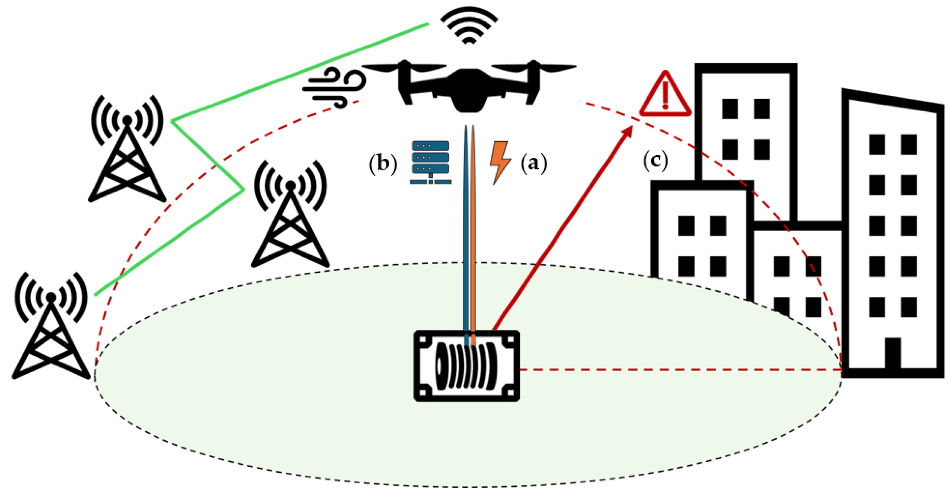
Unlike free-flying/untethered UAVs, tethered drones are physically connected to a ground station via a cable capable of transmitting power, data, or both. This configuration enables significantly extended flight durations and enhances operational stability by leveraging the tether as a physical constraint that attenuates disturbances [
10,
11]. Furthermore, TUAVs exhibit a tightly coupled dynamic behavior resulting from the interaction between the aerial platform and the tether cable. This coupling introduces unique challenges in modeling, control, and stability, setting TUAVs apart from their untethered counterparts. An overview of these newly introduced features is illustrated in
Figure 1.
1.1.1. Power Supply
One of the primary concerns associated with multirotor UAVs is their limited flight autonomy, which typically reaches up to 40 min before requiring battery recharging or replacement. Several approaches have been proposed to overcome this limitation [
12]. By drawing power from a ground-based source via a tether cable, tethered drones can operate for extended durations, potentially indefinitely, thus ensuring uninterrupted operation, consistent performance, and improved energy efficiency. Moreover, the removal of onboard batteries increases the drone’s payload capacity and eliminates issues related to battery lifespan and maintenance [
13].
1.1.2. Wired Data Communication
The employment of a tether cable in UAV systems is not limited to power transmission alone; it also plays a pivotal role in enabling robust and efficient data communication between the aerial platform and the ground station. Optical fibers integrated into the tether establish a wired backhaul connection, enabling high-bandwidth data transfer, which is essential for bandwidth-intensive applications such as high-definition video streaming, real-time sensor data processing, and emerging 6G communication frameworks [
14]. Compared to untethered UAVs relying on wireless links, TUAVs benefit from significantly higher data throughput and reduced transmission latency, due to the inherently greater capacity and stability of the wired connection [
15]. Additionally, the physical tether minimizes path loss, ensuring stronger and more consistent signal quality [
16]. As a result, the tether not only sustains the drone’s power but also establishes a secure, interference-resistant, and low-latency data communication channel.
1.1.3. Flight Safety Measure
The integration of a tether cable into UAV systems significantly enhances flight safety by introducing mechanical constraints that physically limit the aerial platform’s movement. This constraint acts as a passive safety mechanism, mitigating risks associated with power failures, operator errors, and extreme environmental conditions such as strong gusts. Additionally, the tether contributes to system safety by preventing fly-away incidents, minimizing collision risks, and aiding compliance with regulatory safety requirements. Studies analyzing the interaction between sudden UAV movements and tether dynamics help define potential danger zones, primarily influenced by tether strength and impact parameters such as velocity and angle [
17]. This constraint not only defines a safe flight boundary but also facilitates regulatory compliance in restricted airspaces, where physically constrained systems are often subjected to less stringent certification requirements. These advantages make TUAVs particularly appealing for sensitive, high-risk, or long-duration missions. However, the introduction of a tether also creates new safety challenges, particularly in terms of obstacle avoidance and collision management. The cable itself becomes an additional element in the flight environment that is susceptible to entanglement or collision, especially in cluttered or confined spaces. A critical concern is the potential interference between the tether and the drone’s propellers, which must be proactively addressed. This is especially relevant in slack tether conditions or when operating in suspended TUAV configurations [
18,
19]. Mitigation strategies include the use of propeller guards or ducted propeller designs, possibly combined with swiveling arms that extend beyond the main airframe to keep the tether safely clear of the propulsion system [
20]. In complex environments such as urban canyons or vegetated areas, the risk of tether or platform collision increases. Ensuring a collision-free flight path becomes a key safety priority and can be addressed through advanced navigation strategies. Research has emphasized safe landing phase planning [
21], as well as collaborative navigation approaches, both with ground robots for mapping and obstacle detection [
22,
23], and with cooperative TUAV swarms for coordinated movement [
24,
25]. In some cases, it may be beneficial for the tether to intentionally interact with the environment: for example, by planning tether contact points on static structures, a TUAV can effectively reshape its reachable configuration space, thereby expanding its operability to levels comparable with non-tethered systems [
26].
1.2. Application Fields
UAVs have been implemented in many different fields throughout recent years, paving the way for the development of tethered technologies. These enhanced systems leverage the advantages discussed above to surpass the limitations of conventional UAVs. As a result, tethered drones have become increasingly valuable in a variety of mission-critical and time-sensitive applications, which are outlined in the following sections.
1.2.1. Agriculture
In agriculture, UAVs are already used for tasks such as crop spraying, pollination, pruning, and monitoring plant health. Tethered drones further enhance these capabilities by enabling continuous operation. In greenhouse settings, a tethered drone mounted on a mobile ground station can function as a flying end-effector for precision tasks within crop rows [
27]. In open fields, multiple ground-tethered UAVs operating in grid formations can serve as an effective bird deterrence system, leveraging centralized control and extended flight time to manage multiple threats simultaneously [
28].
1.2.2. Marine Emergency
Thanks to their maneuverability and elevated vantage point, in marine applications, TUAVs support tasks such as oil slick thickness monitoring during spill events [
29] and search and rescue operations in mass casualty incidents [
30,
31]. They can also act as aerial communication relays, maintaining stable links and coordination during emergency maritime missions [
32].
1.2.3. Load Transportation
A notable application of tethered drone systems involves aerial load transportation via cable-suspended mechanisms. While these cables may not carry power, they share similar dynamic modeling with power-transmitting tethers. A growing interest in drone-based delivery of goods and medical supplies has driven development in this area. To overcome payload capacity and counteract load swing while improving flight stability, recent approaches have introduced cooperative multi-drone systems, offering improved scalability and fault tolerance through load-sharing redundancy [
33,
34,
35,
36]. Advancements in this field have also focused on suspended load characterization, including the deployment of mobile grippers for object grasping in dynamic outdoor environments [
37].
1.2.4. Inspection and Monitoring
The enhanced endurance and stability of TUAVs can be leveraged for long-duration infrastructure inspection tasks, such as bridge inspections performed by a suspended TUAV that emulates traditional bucket truck-based inspections [
19,
38]. Additionally, creeping TUAVs clinging to the underside of bridges at controlled distances have demonstrated precise crack detection using high-resolution image stitching algorithms [
39]. Tethered drones have also been deployed in challenging underground environments, such as coal mine sites, where GNSS signals are unavailable, radio communication is limited, and visual cues are scarce. In such scenarios, TUAVs have successfully mapped stone mine pillars and assessed structural integrity in confined and debris-filled spaces [
20,
40]. Beyond civil infrastructure, TUAVs are also gaining traction in high-demand inspection scenarios such as nuclear power plants, where continuous monitoring and extended endurance are critical [
41]. Similarly, in aviation environments, tethered systems can support airfield inspections, weather and traffic surveillance, wildlife deterrence, and emergency response coordination [
42,
43].
1.2.5. Airborne Wind Energy (AWE)
Over the past decade, tethered aircraft have been explored for Airborne Wind Energy (AWE) systems, which aim to harvest high-altitude wind more efficiently and with less material than conventional turbines. Among these, tethered drones have been used to follow predefined flight paths while carrying energy-harvesting elements, such as rigid wings [
44] or Magnus-based devices [
45,
46], exploiting the tether tension and the ground-based winch as a power generator.
1.2.6. Meteorology
The extended flight endurance of TUAVs is well-suited for environmental monitoring, particularly in atmospheric sensing applications. For instance, arrays of temperature sensors integrated along the tether can capture vertical temperature profiles with accuracy comparable to meteorological towers, supporting dynamic climate and weather studies [
47,
48].
1.2.7. Painting
The uninterrupted power supply provided by tethered configurations also enables unconventional applications, such as in the arts. Equipped with a stippling mechanism and benefiting from extended flight time, a drone can autonomously apply tens of thousands of ink dots to a canvas without human intervention [
49].
1.2.8. Cellular Networks
UAV-assisted heterogeneous networks have gained significant attention for enhancing cellular coverage and capacity. In this context, TUAVs can serve as aerial base stations (ABSs) or relay nodes, particularly useful when terrestrial base stations (TBSs) are overloaded or unavailable [
50]. Leveraging their stable positioning and continuous power supply, TUAVs have been shown to support user association, resource allocation, and 3D placement optimization to improve overall network performance [
51]. By minimizing path loss and maximizing end-to-end signal-to-noise ratios, TUAV-ABSs can effectively offload traffic and support multiple ground users during peak demand [
52,
53]. Depending on the network topology, TUAVs can also act both as high-altitude relays [
54] and as TBSs replacements [
55], linking untethered UAV relays and ground users. In next-generation networks, TUAV-based drone cells can serve as mobile fronthaul links, offering robust, high-bandwidth connectivity for 6G communications [
14]. To balance the trade-off between power availability and deployment flexibility, intermittently tethered UAVs (iTUAVs) have been proposed, enabling temporary anchoring at ground stations before relocating to optimize mobile user coverage [
56].
1.2.9. Firefighting
While the tether cable has primarily been discussed as a means for power and data transmission, its physical presence can also enable alternative functions in critical operations such as firefighting. In these scenarios, the tether may be replaced or supplemented by a water hose, enabling the TUAV to deliver high-pressure water jets from an aerial position over hazardous fire zones, thus minimizing risk to human responders [
57]. Recent implementations feature recoil-compensated designs that account for the reactive forces of both the water jet and hose dynamics, enhancing flight stability during prolonged firefighting operations [
58].
1.2.10. Field of Defense
TUAVs have become increasingly valuable in defense operations, enabling extended surveillance and reconnaissance missions where continuous situational awareness is critical and risk to human life is high [
59]. TUAV swarms enhance intelligence, surveillance, and reconnaissance (ISR) and defense operations by enabling rapid deployment, persistent multi-angle surveillance, and safe operation in confined or complex environments. In law enforcement or military scenarios, swarms can be used to secure perimeters, monitor vehicle checkpoints, or provide overwatch in urban terrain [
25].
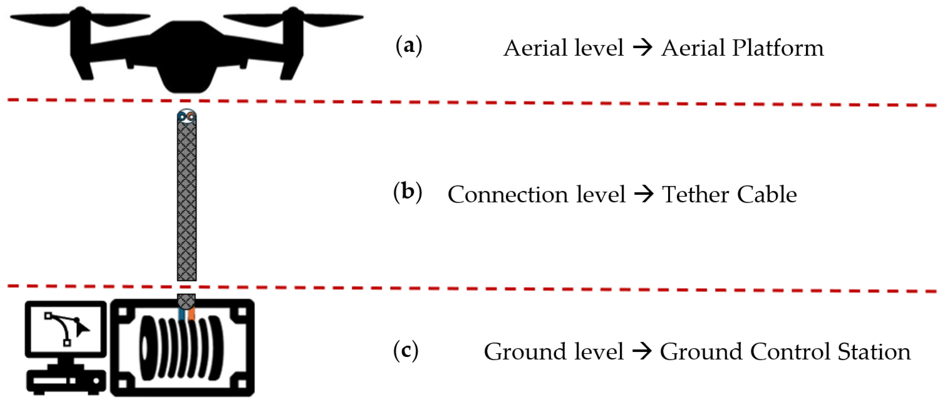
2. System Description
The following section aims to outline the components and spatial configurations of a TUAV multirotor system. For clarity, the system is divided into three levels: aerial, connection, and ground, each encompassing one or more components depending on their spatial arrangement, as illustrated in
Figure 2. Although onboard hardware and sensors are integral to the system, they have been intentionally excluded here, as their complexity and relevance warrant dedicated discussion in a separate chapter.
2.1. Aerial Platform
In a broader sense, the term “Unmanned Aerial Vehicle” encompasses various aerial platforms, provided they are uncrewed. Consequently, the aerial component of a TUAV system is not necessarily a drone by default. Early research on tethered systems primarily focused on helicopters, leveraging existing technologies [
1]. Subsequent studies explored alternative rotor-based platforms, such as rotorcraft with a free-flapping, single-rotor configuration lacking a tail rotor [
2], and the gyromill, a rotorcraft comprising two counter-rotating single-blade rotors and a transverse fuselage with movable fin and tailplane [
3]. Helicopters remained the predominant tethered aerial platform due to their VTOL capabilities [
60,
61], with significant advancements in tethered helicopter systems attributed to the work of Sandino and the research group led by A. Ollero [
62,
63,
64,
65], which laid foundational groundwork for the development of tethered drone literature. This review, however, focuses specifically on the current State of the Art in tethered multirotor drone systems, which offer greater flexibility in spatial and geometric configurations.
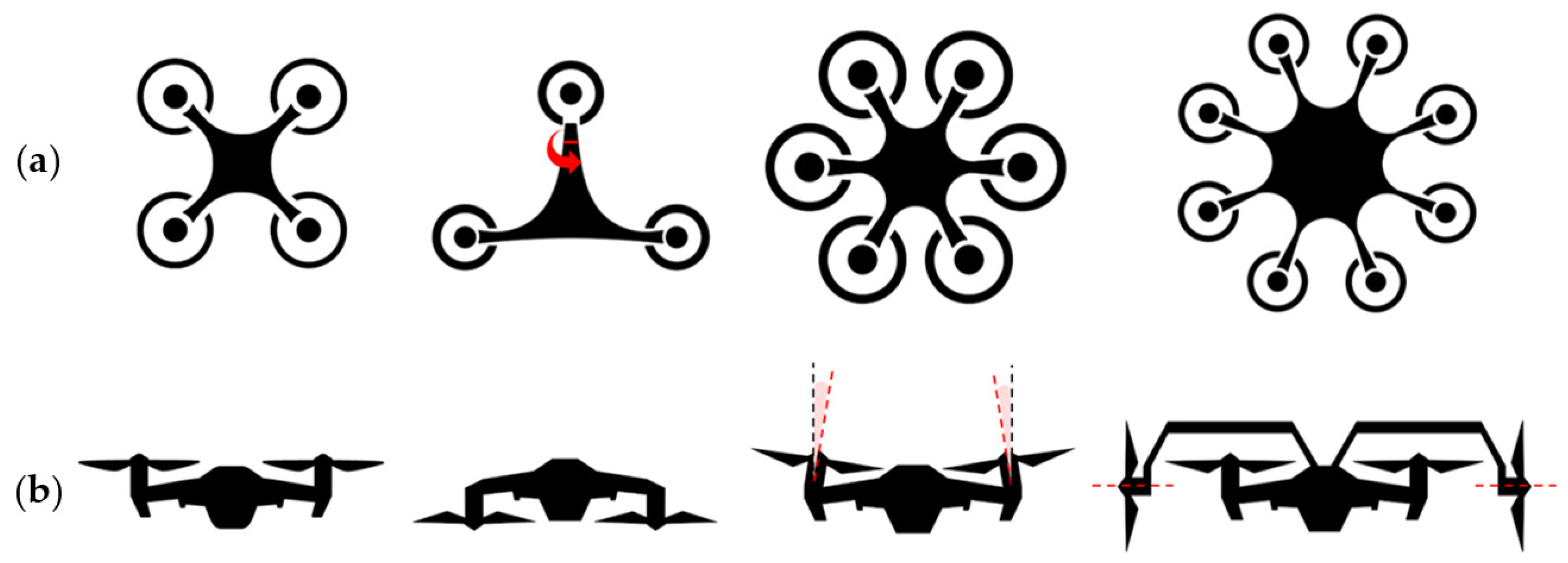
Airframe Configurations
TUAV airframes can be classified according to key physical design parameters that affect flight dynamics and operational roles. Two primary classification criteria are commonly adopted: the number of propellers and the orientation of the propulsion system. These classification schemes are illustrated in
Figure 3. The first classification of TUAVs relates to the number of propellers, which inherently influences the drone’s size and lifting capability. The quadrotor is the most common configuration due to its geometric symmetry and balanced trade-off between maneuverability, payload capacity, and weight efficiency. Tethered hexarotors have been developed for extended endurance [
66] and heavy-duty operations supporting payloads up to 30 kg [
67]. Similarly, tethered octocopter configurations have been investigated for comparable purposes [
68,
69]. An alternative solution is the tilt-trirotor, an asymmetric three-rotor system capable of hybrid flight modes, functioning both as a fixed-wing aircraft and a rotorcraft [
70]. A second classification criterion is given by the propeller orientation, a critical factor in the UAV’s design. The suspended TUAV configuration, with rotors facing downward, is commonly adopted in scenarios where the aerial platform operates below the control station level, such as in bridge inspections, minimizing the risk of tether entanglement [
18,
19,
38]. Tilt-rotor multicopters offer improved wind disturbance rejection and fault tolerance, enabled by servos adjusting rotor tilt angles [
71]. A distinctive layout involves a quadcopter frame augmented with two laterally placed horizontal rotors, designed to counteract aerodynamic drag [
58]. For operations in confined or collision-prone environments, ducted propellers offer improved propulsion efficiency and increase–d protection, albeit with reduced flight performance [
20]. An innovative design further integrates ducted propulsion with tiltable rotors, featuring two vertical ducted propellers mounted on rotating shafts [
72].
2.2. Tethered Connection
The connection level represents the physical and functional link between the aerial platform and the ground station. It includes both the tether cable, which serves as a mechanical, electrical, and data conduit, and the aerial power conversion module, responsible for adapting the ground-supplied power to the UAV’s onboard requirements. This section addresses the structural and functional characterization of both those two elements.
2.2.1. Aerial Power Module
The aerial power module is responsible for converting the high-voltage power transmitted through the tether into a regulated low-voltage supply suitable for the UAV’s propulsion and onboard electronics. This unit is a critical interface between the tethered ground supply and the UAV’s power architecture, and its design is primarily constrained by efficiency, thermal management, and weight. A high-frequency AC multi-phase transmission system can be adopted to minimize cable and onboard converter size, hence enabling larger payloads and extended mission durations [
41,
73]. The onboard conversion module employs resonant energy transfer to improve efficiency [
41,
73,
74] and incorporates modular converter designs—such as parallel DC-DC converters and isolated compartments—to further reduce the system’s bulk [
73,
74,
75]. To address thermal challenges, forced-air ventilation mitigates overheating under peak loads [
75], while aluminum heat sinks and dual cooling fans support effective thermal dissipation [
66]. To ensure safe emergency landings during power failures, a backup battery system is typically connected in parallel to the UAV’s DC bus, automatically activating when a voltage drop is detected [
66]. These systems often include pre-charged batteries, solid-state relays (SSRs), and fast-switching diodes to enable rapid activation. Integration with the low-voltage power bus and logic-controlled triggering circuits ensures reliable operation and minimal interference with the main power supply chain [
76].
2.2.2. Tether Cable
Cable selection is a key design phase in TUAV system integration, requiring careful consideration of multiple performance parameters. This typically involves a trade-off between minimizing transmission power losses and reducing overall cable weight to preserve aerial payload capacity [
77,
78]. A standard tether cable, illustrated in
Figure 4, is composed of several concentric layers, each serving a distinct function [
79,
80]:
An outer fluoroplastic insulation sheath for environmental protection;
High-voltage copper conductors, each with individual insulation jackets for safe power transmission;
An integrated optical fiber module containing one or multiple fiber-optic lines for high-speed data communication;
An inner Kevlar harness, providing tensile strength and durability under mechanical stress.
Figure 4.
Standard drone tether cable section and structural composition [
79].
Figure 4.
Standard drone tether cable section and structural composition [
79].
While fiber-optic communication is widely regarded as the optimal solution for data transmission in TUAV systems, several alternative technologies allow wired data transmission via electrical conductors embedded in the tether [
81]. Among these, Power Line Communication (PLC) has gained interest in its ability to transmit both power and data over the same wire pair, thereby reducing cable complexity. Another common alternative is the use of twisted-pair Ethernet cables, which can offer a compatible solution with typical UAV onboard hardware. Despite the feasibility of these electrical methods, optical fiber remains the preferred choice for high-performance TUAV applications due to its complete immunity to electromagnetic interference (EMI), low latency, and exceptionally high data throughput, which support real-time video streaming, sensor feedback, and control commands.
2.3. Ground Control Station
The Ground Control Station (GCS) in a tethered UAV system serves as the central hub for power delivery, flight monitoring, and UAV control, enabling safe and stable operation throughout extended missions. Unlike conventional UAVs, tethered platforms require specialized ground infrastructure to manage continuous power transmission, communication links, and tether handling mechanisms. The primary components of a typical GCS include [
82]:
Power Supply Unit: Converts and regulates AC or DC inputs (typically from grid, generator, or battery pack) to DC outputs suitable for transmission through the tether.
TMS: Includes an automated winch for tether deployment/retrieval and a slip ring for uninterrupted electrical connection during rotation.
Communication Interfaces: Facilitates real-time control and telemetry via ground-to-air communication modules.
Monitoring and Control Interface: A user-accessible interface (e.g., a laptop or control console) running mission planning and UAV management software (e.g., QGroundControl), providing operators with live data and system status.
The GCS is designed to ensure reliable power and data links, precise tether tension control, and robust mission coordination, which are essential for safe TUAV operations.
2.3.1. Tether Management System
The TMS is a compact, ruggedized ground unit that integrates key components of a TUAV’s ground level. Its primary roles include storing excess tether, sensing and controlling tether parameters, and in some cases, housing the power supply, such as a battery pack. Typical TMS components include
Tether cable and spool/reel;
DC motor actuator;
Tether sensors (length, tension, elevation, and azimuth angles);
Control unit;
Landing platform;
Power source.
This section presents an overview of experimental TMS configurations, while detailed sensing and control strategies are addressed in later chapters. A critical requirement of any TMS is rapid spool response, ensuring the system reacts promptly to UAV movement. Uniform cable distribution and accurate tension sensing are achieved through various winding mechanisms, including pulley systems [
67,
83], plane-fixed tether outlets [
61,
84], passive sensorized followers [
83,
85,
86], and rotary rods [
41]. To prevent cable twisting during spool rotation, slip rings are commonly employed [
18,
86]. Tether angles can be sensed via a universal joint, while tension can be measured using spring-loaded lever arms [
40,
87] or indirectly estimated using a powder clutch applying a constant torque, assuming a known spool diameter [
83]. Notably, one configuration uses a vertically rotating spool to optimize spatial layout [
41]. Some advanced TMS setups also integrate the landing platform into the system structure, which can be fixed [
84,
87], elevated [
61], or self-leveling [
40], increasing system stability and adaptability.
2.3.2. Commercial Off-the-Shelf Systems
Several commercial TMS solutions are available on the market, typically emphasizing mechanical robustness and power transmission efficiency, aspects often peripheral to current academic research. These systems are generally compact, rugged, and box-shaped, designed to operate with external power units. Tether tension control varies by manufacturer, ranging from constant-tension mechanisms [
88,
89], to set-velocity winding [
90], and multi-mode tension settings with retract functions [
91,
92]. Only a few commercial models support battery operation [
93], and just one is reported to provide real-time cable departure angles [
94]. Some all-in-one COTS solutions integrate the drone, tether cable, and aerial power module into a single package. For example, Fotokite offers a tethered hexacopter with a rectangular frame and rooftop deployment cases tailored for firefighting and first-response applications [
95]. Hoverfly provides modular, network-capable systems designed for ISR missions and variable-height communications, supporting a range of payloads in an open architecture design [
96].
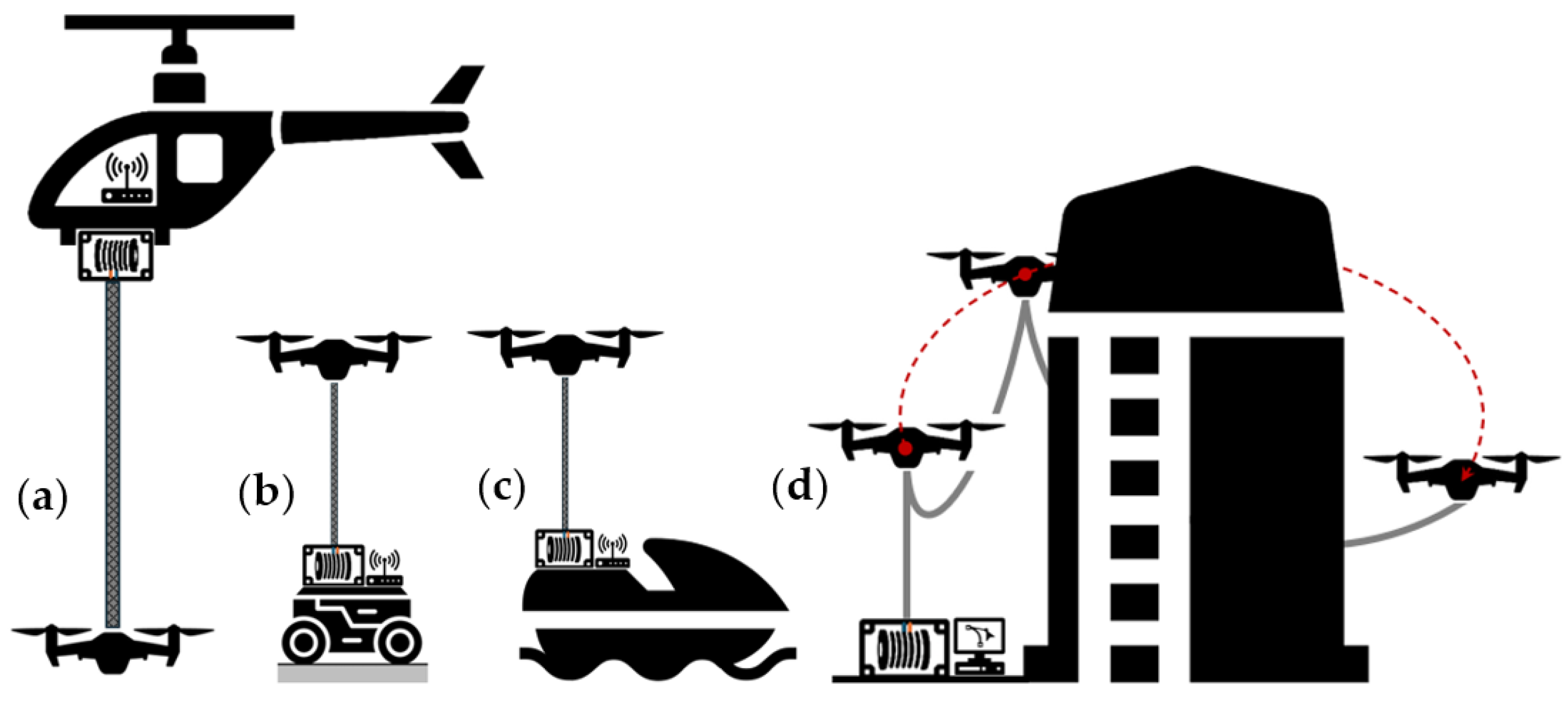
2.4. Multi-Robot Systems
An overview of tethered multi-robot systems is presented in this section to complete the analysis of TUAV configurations. Previous examples have already highlighted the versatility and potential of tethered platforms. As illustrated in
Figure 5, the specific characteristics of the operational environment dictate the overall system architecture, particularly when coordinating heterogeneous robotic units, such as aerial and ground-based elements.
2.4.1. TUAV/UGV Team
In inspection and exploration tasks, integrating a TUAV with an Unmanned Ground Vehicle (UGV) unlocks new operational capabilities. One key advantage is the creation of a mobile tether anchor point, with the UGV serving as a moving power and tether management unit. This enhances the UAV’s maneuverability in cluttered or confined environments while reducing the risk of tether entanglement [
40]. In such configurations, the UGV may carry the battery pack, winch, and tether sensors, acting as a full ground segment for the airborne platform, even when using a tracked or wheeled base [
97]. This setup supports collaborative navigation, with TUAV and UGV sharing data for joint environment mapping and enhanced situational awareness [
26,
70]. A marsupial robot configuration, where the TUAV assists the UGV’s motion planning, has been shown to enable safe traversal through unknown terrain using tether-based path planning derived from tether dynamics [
23]. Beyond sensing, the TUAV has also been employed for tether attachment to elevated structures, facilitating UGV ascent by enabling it to lift its own weight via an integrated winch system [
98]. Additionally, a multi-UGV setup can enhance TUAV pose stabilization by applying distributed tether forces to counteract environmental disturbances such as wind [
88].
2.4.2. TUAV/USV Team
A distinct operational scenario is presented by the marine environment, where the multi-physics complexity demands additional modeling, particularly concerning surface water dynamics, often addressed through the floating buoy model [
99]. Several studies have demonstrated that the forward-surge velocity of a buoy can be controlled by adjusting the thrust of a tethered UAV connected via a taut cable [
100,
101,
102]. This work was later extended by the same research group to consider slack cable configurations, allowing greater freedom of movement for the UAV around the buoy [
103]. In such systems, the tethered UAV operates in coordination with a floating platform, typically an Unmanned Surface Vehicle (USV) serving as the buoy component. Similar to TUAV–UGV cooperative teams, the aerial agent enhances the visual navigation capabilities of the marine vehicle, particularly in search and rescue missions, by providing an elevated field of view [
30].
2.4.3. TUAV Swarm
Among multi-robot TUAV configurations, one notable concept is the UAV swarm, wherein multiple drones operate in a coordinated manner, often connected via tethers. This layout, referred to as a System of Tethered Multicopters (STeM) [
104], features serially connected UAVs cooperating to transport payloads [
34,
35] or to support precision spraying tasks using a suspended tube with an integrated nozzle and tethered power line [
105]. Cable management across swarm units remains a primary challenge, especially in complex environments with obstacle-dense zones [
24]. Cable anchoring and reeling at each intermediate drone is typically managed via a gimbaled winch [
104] or a pulley-based double-gimbal mechanism [
106]. Depending on operational needs, the tether’s ground anchoring may be either fixed or mobile [
106]. Additionally, multi-UAV cooperation can be leveraged for tethered docking and deployment scenarios, for example involving a helicopter-like UAV platform deploying a tethered quadrotor for frequent delivery missions [
107].
2.4.4. TUAV + Manipulator
An emerging application of TUAVs involves their integration into multi-robot systems where the aerial vehicle is physically coupled with a robotic arm. In a particularly innovative configuration, the system is composed of two cooperative robotic entities: a UAV providing mobility and positioning, and a tether-driven continuum robot acting as a flexible manipulator. The ground station, functioning as a third key subsystem, houses actuators and control units, transmitting mechanical power through the tether to the robotic arm mounted on the UAV. This approach highlights the potential of TUAV-based multi-robot systems for enabling physical interaction with the surrounding environment [
108,
109].
Although each of the multi-robot TUAV configurations discussed in this section demonstrates unique operational advantages, they also pose substantial engineering challenges that limit real-world deployment. A comparative overview of these configurations is provided in
Table 1, highlighting their typical applications, key strengths, operational limitations, and ongoing research gaps. TUAV–UGV teams benefit from increased maneuverability and terrain adaptability but are highly sensitive to tether routing complexity, especially in GPS-denied environments. TUAV–USV cooperation introduces new modeling complexities due to surface wave dynamics, requiring robust adaptive control to handle oscillatory tether tension. TUAV swarms offer increased task parallelism and fault tolerance yet suffer from entanglement risks and demand sophisticated cable-aware coordination algorithms. Finally, the integration of robotic arms, such as the tendon-driven continuum robot, significantly expands manipulation capabilities but complicates control due to structural flexibility and added inertial dynamics. These trade-offs emphasize the need for integrated modeling, real-time coordination algorithms, and cross-domain simulations that include tether mechanics, multi-agent behavior, and dynamic environments.
3. Mathematical Modeling
Mathematical modeling of tethered aerial systems first appeared in the literature in the early 1960s, initially focused on helicopters [
1], rotorcraft platforms [
2,
3], and general tethered flight vehicles [
110]. While early studies did not consider tethered multirotor UAVs, they provided foundational concepts for later developments. Although tethered helicopters with tail rotors fall outside the scope of this review, key contributions, such as those from Sandino’s group [
62,
63,
64,
65], remain valuable for understanding rotor-tether dynamics. This chapter provides an overview of modeling approaches for the core components of a tethered multirotor UAV system:
3.1. Multirotor UAV Model
While various rotor configurations exist, this section focuses on the quadrotor UAV, as it is the most widely modeled platform in the literature. The mathematical formulation adopts several common assumptions to simplify the dynamics [
111]:
For clarity, the shorthand notation below will be used for trigonometric functions further in the dissertation.
3.1.1. Cartesian Reference Frame
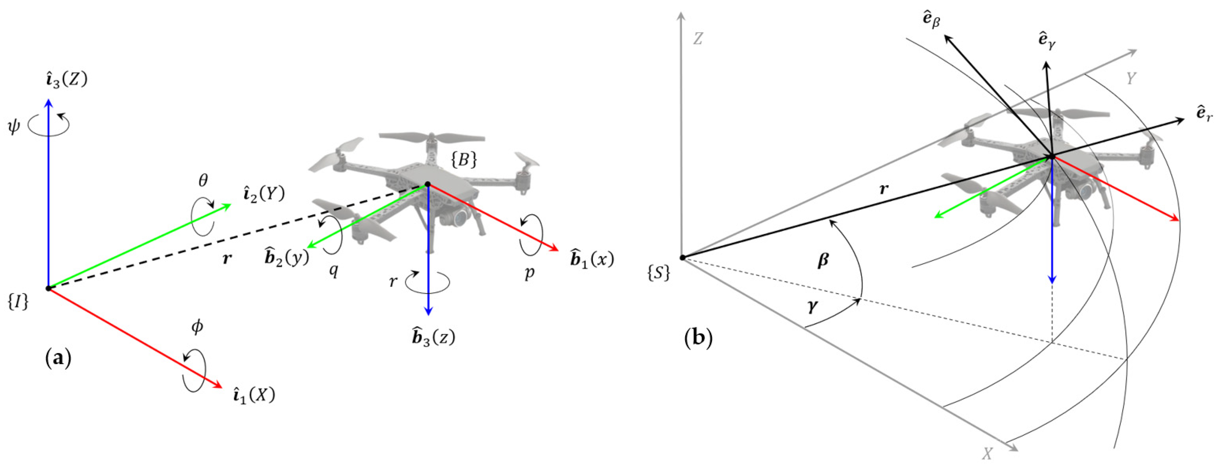
The UAV’s motion is usually described using two Cartesian reference frames, as illustrated in
Figure 6a: an inertial frame
, fixed to the ground with unit vectors
, and a body-fixed frame
, located at the UAV’s CoG and typically defined with unit vectors
, using the right-hand rule [
112] or the North-East-Down (NED) convention, where
points downwards [
113]. The attitude orientation of the UAV with respect to the inertial frame is defined using Euler angles, typically in the ZYX sequence, and represented by the rotation matrix
. The relation between the two Cartesian frames is expressed as [
114]
Angular rates are defined starting from the angular velocity in the body-fixed frame
, which is related to the inertial frame through the following relation.
The time rate of change in Euler angles is calculated by inverting the previous expression.
3.1.2. Spherical Reference Frame
An alternative and effective representation is the spherical reference frame [
103], particularly useful when modeling tether dynamics, as later discussed in the unified model section. The UAV’s Cartesian position
is expressed in the spherical frame
with the coordinates
and corresponding unit vectors
. Here,
is the radial distance from the origin,
is the elevation angle from the horizontal plane, and
is the azimuth angle between the positive
axis and the projection of
on the
plane, as illustrated in
Figure 6b. The transformation from spherical to Cartesian coordinates is achieved through two sequential rotations:
Afterwards, relations between Cartesian and spherical frames are established.
where
.
3.1.3. Equations of Motion
The Equations of Motion (EoM) for a TUAV system can be derived using either the Euler–Newton or Euler–Lagrange formalisms [
111]. In the body-fixed frame, the UAV’s translational and rotational dynamics are governed by Newton’s second law, which relates external forces and moments
to the time derivatives of the linear and angular momenta
and
[
114].
where
is the 3
3 identity matrix,
is the UAV mass,
is the constant inertia tensor, and
is the vector of linear velocities in the body frame. Due to symmetry assumptions previously made, the inertia tensor has the form of a diagonal matrix.
Using the Euler-Lagrange approach [
115], the UAV’s dynamics are expressed in terms of a set of generalized coordinates
, representing its translational and rotational degrees of freedom. The Lagrangian
is defined as the difference between kinetic and potential energy:
The EoM are derived from
where
is the vector of external forces and moments, expressed in the body-fixed frame. The matrix-condensed form of EoM becomes
The final form of the UAV’s EoM depends on the external forces and moments considered, as illustrated in
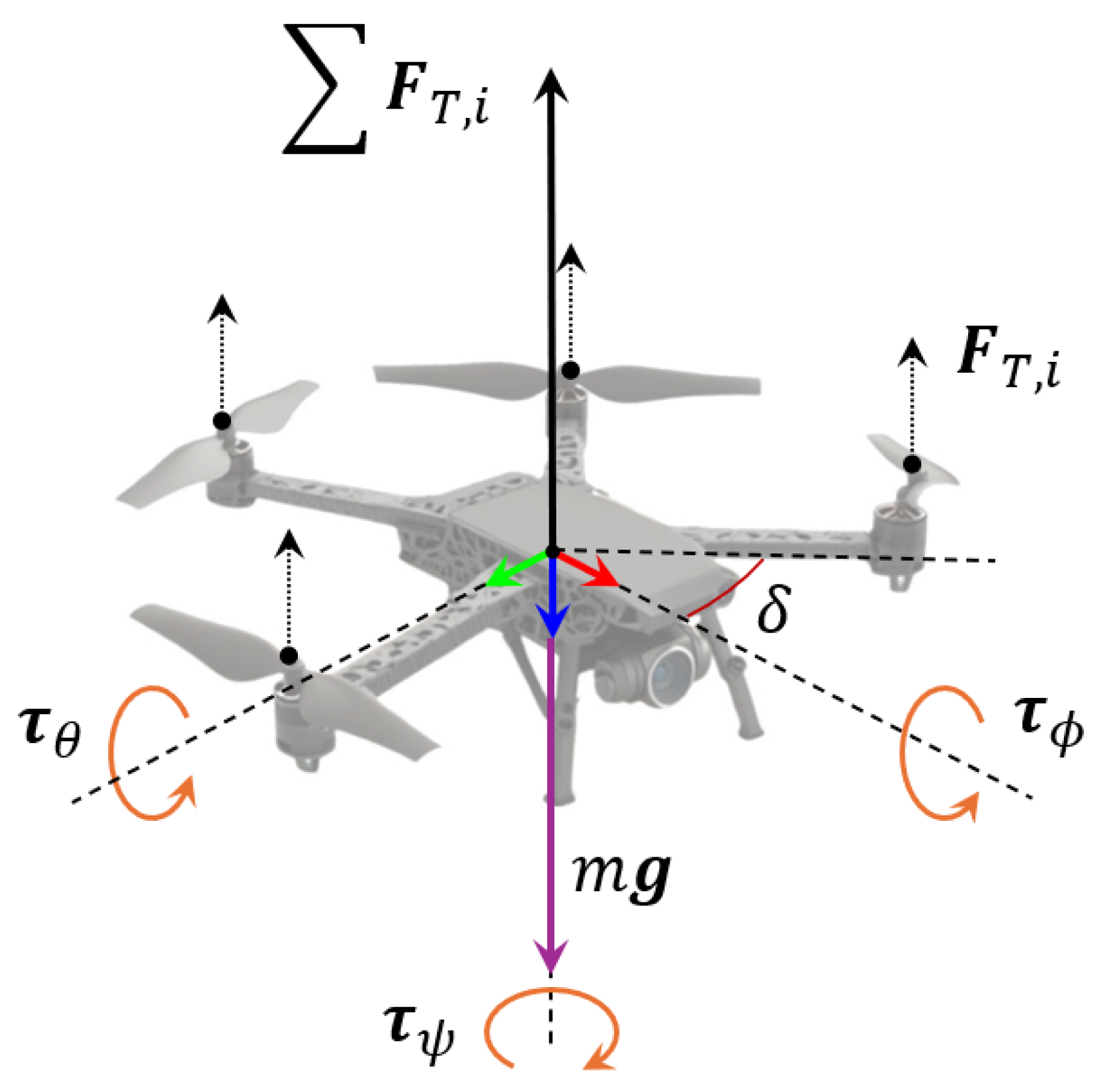
Figure 7. The main active force is the collective thrust
generated by the rotors, each one spinning at angular velocity
:
where
is the thrust coefficient, typically obtained from static tests. Rotor drag, resulting from blade aerodynamics, induces a net yaw torque based on the rotational direction of each rotor:
with
as the drag coefficient. Assuming an X-configuration quadrotor, the angle
between each arm and the body axis must be considered when computing rolling and pitching moments:
To improve physical realism, more advanced models may also incorporate effects such as hub forces, gyroscopic moments, and ground effects [
113]. The extended EoM for the quadrotor are
EoM are commonly formulated using the traditional Euler angle parametrization. However, it is well known that Euler angle parametrizations suffer from singularities, particularly when the pitch angle
approaches ±90°, leading to a phenomenon known as gimbal lock. In such configurations, two of the three rotation axes become aligned, resulting in a loss of one degree of freedom and introducing numerical instability and ambiguity in the attitude representation. This issue poses significant challenges for UAV control and estimation algorithms, especially during aggressive maneuvers or when operating in near-singular configurations. To overcome these limitations, quaternion-based representations are often adopted. Quaternions provide a globally non-singular, compact, and computationally efficient means of representing orientation, making them well-suited for real-time UAV attitude dynamics and control. The UAV’s attitude dynamics can therefore also be described using quaternion notation [
68,
69,
116]:
where
is the unit quaternion representing the UAV orientation. The quaternion formulation ensures a smooth and continuous description of the UAV’s attitude over the entire 3D rotation space, avoiding the singularities inherent to Euler angles and thereby improving robustness in both estimation and control applications.
3.2. Tether Cable Model
The tether cable plays a critical role in the dynamic behavior of a TUAV system, mainly because of physical constraints. Its mechanical response depends heavily on configuration and tension conditions. When connected between a ground anchor and a flying drone, the cable can primarily exhibit two geometric configurations: a taut cable, modeled as a straight line under high tension, and a slack cable, where gravitational effects dominate, causing the cable to deflect into the characteristic catenary curve [
117]. This section introduces the fundamental modeling approaches for both regimes, outlining their assumptions, applicability, and relevance to tethered flight dynamics.
3.2.1. Tether Statics
In static conditions, the tether can assume two primary configurations: taut and slack. In the taut cable case, the tether acts as a position and force constraint, enhancing UAV stability and defining a safe operating boundary via the winch control system [
10]. When the tether is short, lightweight, and inextensible, it can be approximated as a massless, rigid link, exerting a single tensile force aligned with the cable [
118]. In contrast, a slack tether is influenced by gravity and aerodynamic forces. This configuration, together with a fast-responding TMS, allows the system to absorb wind disturbances, heave disturbances, and cable stiffness, assuming quasi-static behavior, valid when aerodynamic forces are negligible relative to cable tension [
114,
119]. The tether shape is modeled using the catenary equations, derived from the static equilibrium of an infinitesimal cable segment [
120,
121]:
where
is the vertical coordinate,
is the radial coordinate, and
is the catenary scale factor, further defined by the horizontal tension at the anchor point
, the linear mass density of the cable
, and the gravity acceleration
;
are integration constants defined by boundary conditions. In symmetric setups, as the one illustrated in
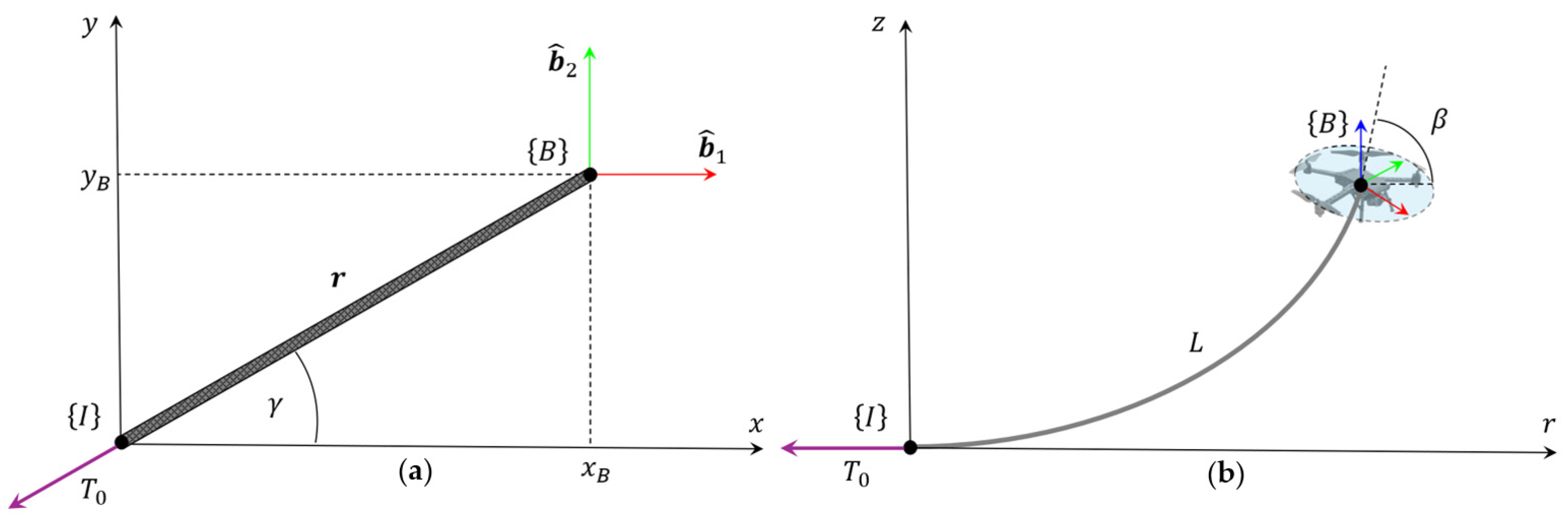
Figure 8, simplified forms are used to calculate tether parameters such as elevation angle
and curved cable length
[
122]:
While most models assume a fixed anchor point, adaptations exist for mobile bases such as UGVs [
97] or USVs [
119]. Similar principles have also been applied to hose-based tether systems [
58]. Overall, static models are most appropriate for low-speed or hovering applications, where inertial effects are minimal.
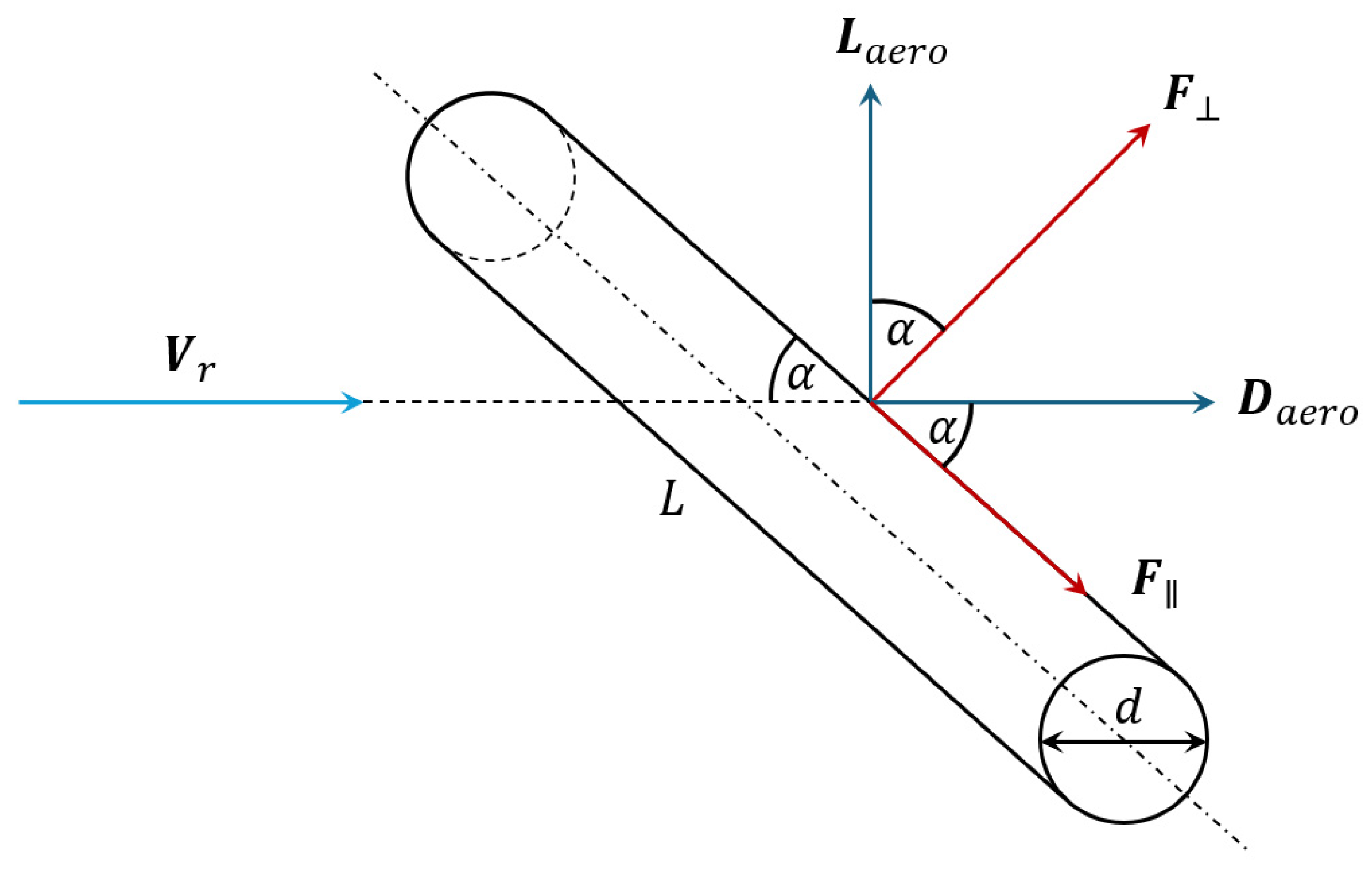
3.2.2. Tether Dynamics
Tether dynamics modeling captures time-dependent behaviors such as inertia, tension propagation, and vibrational effects, which become critical during high-speed maneuvers, wind disturbances, or any condition where oscillations may destabilize the UAV. These dynamics can be addressed using two main approaches:
A discrete model, where the tether is divided into lumped segments;
A continuous model, where the tether is treated as a deformable elastic body.
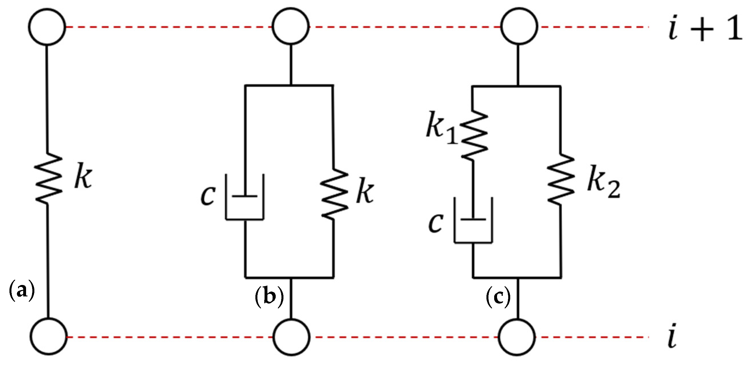
In discrete formulations, the tether is modeled as a series of rigid or viscoelastic elements, as illustrated in
Figure 9. Common choices include the Kelvin–Voigt and Standard Linear Solid (SLS) models [
123]. For slack cables, segment masses are typically placed at the upper joints, with forces transmitted via springs [
124] or spring-damper pairs [
2]. The same principle can be adapted to taut cables using a single linear-elastic [
125] or viscoelastic element [
63,
68,
69].
When cables are long, thin, and under constant tension, they can be modeled as 2D elastic strings using wave-based partial differential equations (PDEs) of an elastic string, under some basic assumptions [
126]:
Bending, shear and torsional deformations are negligible;
Cable density , section , Young’s modulus are constant;
Cable tension is dominant along the longitudinal direction;
Small angles approximation.
Longitudinal and transverse dynamics are governed, respectively, by
with wave speeds
and natural frequencies
given by [
17,
127]:
Here,
and
are the longitudinal and transverse displacements,
is the undeformed string length, and
is the vibration mode. Lagrangian dynamic strain and the related strain energy in the cable are calculated using [
29,
127]:
where
is the arc length and
is the equilibrium curvature. For stiff or short tethers, bending effects are non-negligible and the Euler–Bernoulli beam model is used [
128]. Continuous models support modal analysis [
129], impact stress analysis [
17], finite element implementations [
29], and vibration response prediction [
127]. UAV motion or wind can excite tether vibrations. When those external disturbance frequencies align with the cable natural frequencies, resonance may occur, generating large-amplitude oscillations. Aerodynamic forces
acting on cable segments of length
and diameter
are modeled using the cross-flow principle [
116,
130]:
where
is the air density at a given altitude,
is the relative velocity between the wind flow and the cable segment, and
are the lift and drag coefficients. Considering the incidence angle
of the wind flow, the projected aerodynamic forces, as illustrated in
Figure 10, are
3.2.3. Tether Electrical Model
As the primary role of the tether is power transmission, basic electrical modeling is essential. The internal resistance of the cable
, which causes voltage and power losses, is defined by
where
is the conductor’s resistivity,
is the cable length, and
the cross-sectional area. The corresponding voltage drop and power loss are [
84]:
where
is the operating current. Minimizing
while keeping the cable lightweight introduces a design trade-off between cable diameter and length, key factors in TUAV endurance and lift capacity. For AC power transmission, cable inductance also becomes relevant, contributing to additional losses at higher frequencies [
41].
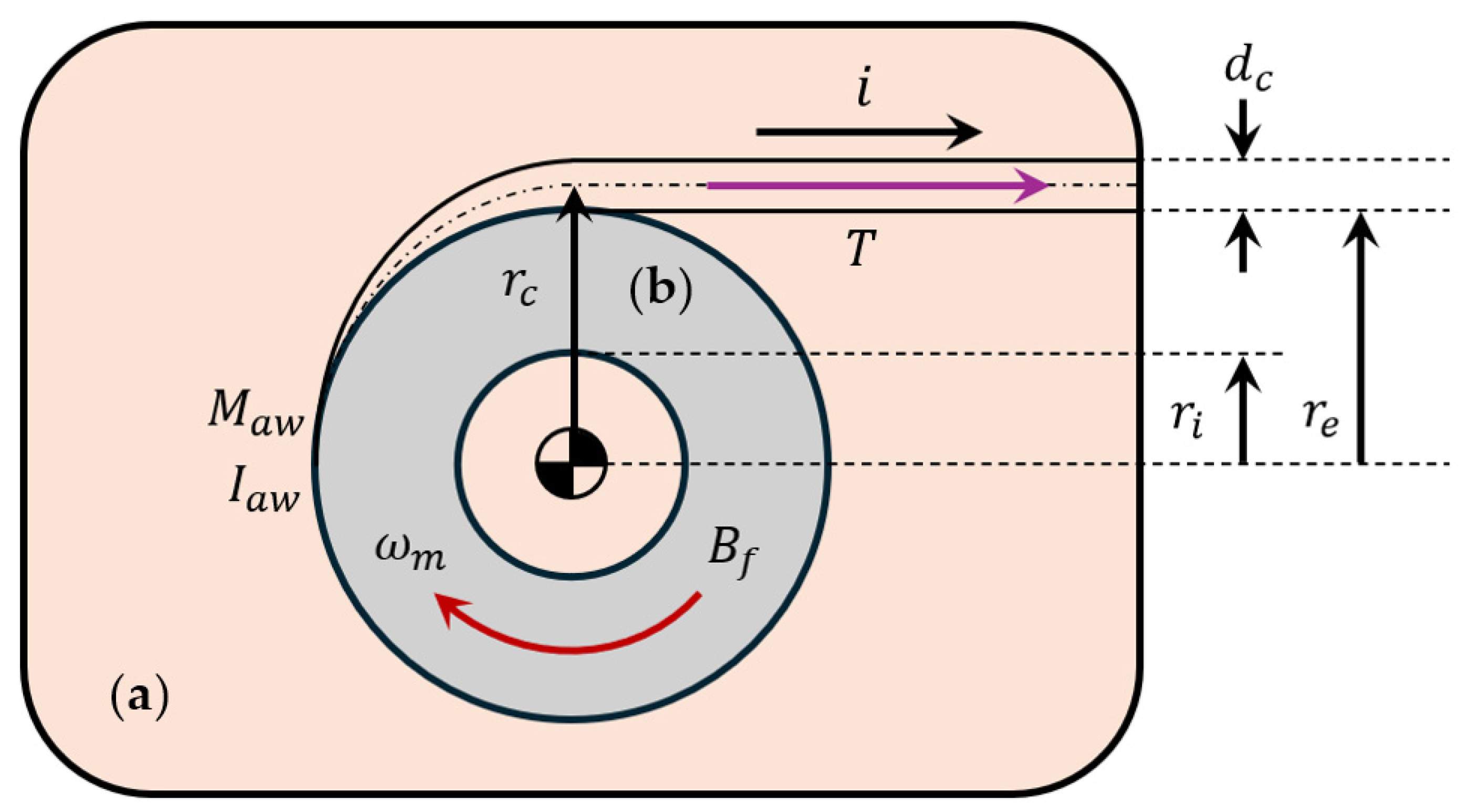
3.3. Automated Winch Model
The ground-controlled winch consists of a hollow spool mounted to a permanent magnet DC motor, used to control tether length and tension [
125]. This section addresses the mechanical and electrical modeling of the winch; sensor-related aspects are discussed in a later chapter.
3.3.1. Mechanical Model
To model the system, the total mass
and moment of inertia
of the winch assembly are given by [
104]
where the subscripts
,
and
indicate, respectively, the DC motor, the spool and a cable of diameter
; furthermore,
and
are the external and internal radii of the spool,
is the motor angular progress, and
is the effective winding radius, calculated as
Both geometric and dynamic parameters of the winch model are illustrated in
Figure 11.
Cable length
can be estimated from a motor angle encoder using a second-order polynomial fit [
85]:
where
,
and
are polynomial coefficients to be experimentally determined. Assuming a single cable layer, the unwinding rate
is calculated as [
63]
where
is the motor shaft speed. If the cable is treated as a linear spring, tension
is expressed as [
106,
125]
where
is the cable elasticity coefficient and
represent its longitudinal deformation.
3.3.2. Electrical Model
The motor’s electrical dynamics are modeled by [
106,
125]:
where
and
are motor’s voltage and current, and
are the motor’s inductance, resistance, and back-emf constant, respectively. The electromechanical model becomes [
106,
125,
131]:
where
is the torque constant and
is the viscous friction coefficient of the motor.
3.4. TUAV Unified Model
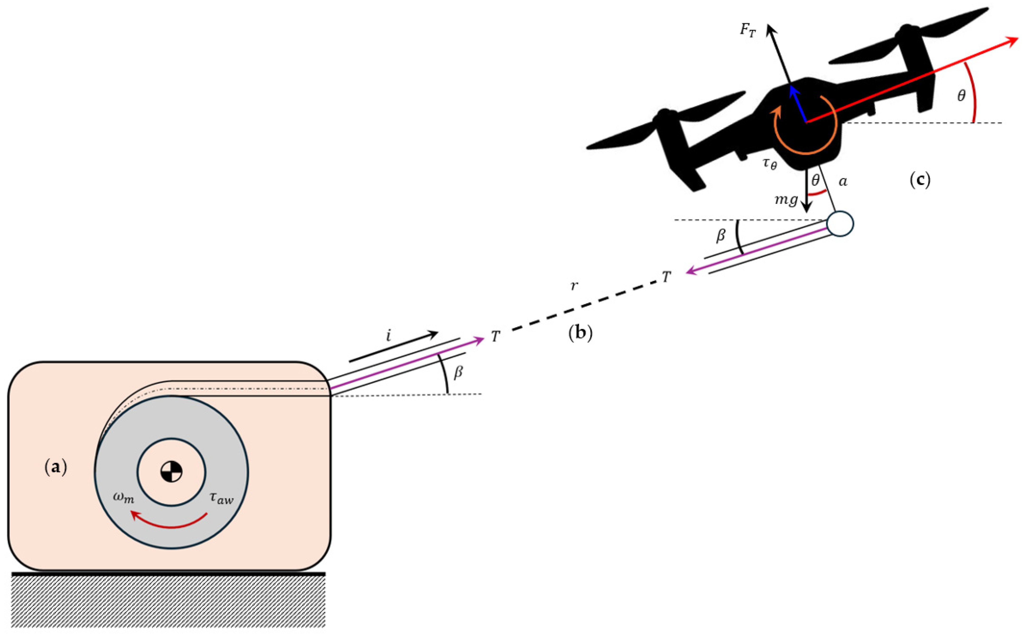
The complete dynamics of a TUAV system are fully characterized only when the tether cable and automated winch dynamics are integrated into the drone’s core EoM motion. Depending on the level of fidelity and assumptions made different unified models can be formulated. This section outlines the main modeling strategies used in the literature to describe the coupled drone–tether–winch dynamics.
3.4.1. Tethered Drone Dynamic Model
In a taut tether configuration, the UAV and winch dynamics are coupled through the tension force acting along the cable. Unified models often neglect cable mass and elasticity, assuming a massless, inextensible link to simplify the analysis. A basic 2D Cartesian model introduces the effect of cable tension
on UAV translational dynamics [
132]:
where
is the drone pitch angle and
the elevation angle. The taut cable condition is enforced by the constraint
at each time instant. The tension is derived from force equilibrium along the cable direction as
By representing the tension vector in spherical coordinates as
, and considering an off-center tether attachment defined by a lever arm
, the set of EoM (14) is updated to reflect the influence of these external forces and moments, expressed in the inertial frame as follows [
103,
133]:
where
and
are the rotation matrices mapping from spherical to body-fixed, and from body-fixed to inertial frames, respectively. For full coupling with the winch dynamics, an initial passive model assumes a constant torque
, with cable length governed by drone thrust alone. The resulting system is [
134,
135,
136]
where the term
represents the cable length variation acceleration. Using a spherical-coordinate-based inertial frame, UAV dynamics can be expressed in terms of radial position, elevation, and azimuth angles. Since tension acts solely along the radial direction, the 3D model can be reasonably reduced to a 2D planar case by neglecting azimuthal effects [
125], as illustrated in
Figure 12. Defining the drone’s CoG in polar coordinates
, the EoM are given as [
99,
100,
101,
125]
Adding a controllable winch, where cable length is regulated via the motor torque
and angular speed
, leads to a fully coupled model [
10,
11]:
subject to the taut cable constraint
The term
accounts for losses due to viscous friction [
45,
46], while tether length and UAV motion are related via
. This model captures the key mechanical interactions in TUAV systems involving a taut cable and active winch.
3.4.2. Tethered Drone Power Draw Model
The nominal power required from the ground power supply is defined as
where
is the total power drawn by the drone due to thrust generation and
accounts for losses in the tether voltage conversion system. Following the helicopter theory approach, drone power consumption can be analyzed in three stages: ideal, mechanical, and electrical power. The ideal thrust power is estimated as [
25]
where
and
are the weights of the drone and deployed tether,
is the air density, and
is the rotor disk area. The mechanical power accounts for aerodynamic inefficiencies via the figure of merit (FOM):
Finally, incorporating motor efficiency
, the total electrical power required by the drone becomes
Substituting into Equation (42) yields the drone’s effective power demand. To obtain the overall TUAV power model, tether transmission losses (25) are added:
3.5. Comparative Analysis and Modeling Trade-Offs
The mathematical modeling of TUAV systems spans multiple interconnected domains, namely, the aerial platform, the tether cable, and the winch mechanism. However, synthesizing these distinct models into a unified and computationally efficient framework remains an open challenge, particularly when seeking a balance between physical accuracy and real-time implementability. Each modeling domain is introduced below, and a comparative overview of their advantages, limitations, and best-use scenarios is summarized in
Table 2.
3.5.1. UAV Platform Dynamics Modeling
The UAV platform is commonly modeled as a rigid body using either the Euler–Lagrange or Newton–Euler approach. The former provides a structured, energy-based formulation well-suited for generalized coordinates and symbolic derivation, while the latter offers a more intuitive force–moment representation in Cartesian space, making it popular in control applications due to its simplicity and numerical efficiency. These models typically assume a symmetric, rigid multirotor and neglect effects such as propeller gyroscopic forces, frame flexibility, or aerodynamic drag unless higher-fidelity models are employed. While adequate for trajectory tracking and basic control, such simplifications limit accuracy during aggressive maneuvers, physical interaction, or in the presence of external loads. Quaternion-based or geometric methods are sometimes used to avoid singularities in full 3D attitude representation.
3.5.2. Tether Cable Dynamics
The tether, being a slender, flexible element, introduces complex dynamics that are highly sensitive to its tension state, mass distribution, and environmental interactions. Discrete models segment the tether into a series of viscoelastic links or rigid rods connected by joints with spring-damper properties. These models are computationally lightweight and can be efficiently integrated into real-time simulation or control loops. They are particularly suitable for taut tether conditions, where the tether behaves nearly as a straight constraint with minimal curvature, such as in hovering or slow, controlled maneuvers. However, these models often fail to capture the rich vibrational behavior and shape deformations present in slack or partially tensioned regimes, where gravitational and aerodynamic effects dominate. Continuous models, on the other hand, treat the tether as a deformable elastic body governed by wave-based PDEs. These allow for the simulation of longitudinal and transverse vibrations, mode shapes, and strain energy distributions, making them ideal for high-fidelity offline simulations and modal analysis. Incorporating catenary geometry, aerodynamic forces, and nonlinear tension propagation, these models offer a much closer approximation to physical behavior, especially in long or low-tension cables. However, their computational cost, sensitivity to parameter uncertainties, and complexity in boundary conditions make them impractical for embedded control applications. The choice between taut vs. slack tether modeling further influences both the form of equations and their solvability. Taut cable models often treat the tether as a massless inextensible link, simplifying integration with the UAV dynamics but neglecting internal cable dynamics. Slack models, by contrast, necessitate catenary equations and more elaborate curvature analysis, making them better suited for applications like TUAV/UGV or TUAV/USV systems operating with varying cable geometries or contact points.
3.5.3. Integrated UAV-Tether-Winch Dynamics
More advanced models fully couple the UAV, tether, and winch dynamics. The winch subsystem, typically represented by electromechanical models with motor inertia, spool radius, and tension feedback, introduces actuation dynamics that affect both cable length and force regulation. These integrated models are essential when using active TMS for coordinated drone-winch control. At a basic level, the winch can be modeled as a passive element applying a constant or predefined torque. This simplification eases integration with UAV dynamics and suffices when tether length is not actively regulated. However, it neglects the dynamic interaction between spool inertia and UAV motion, which can degrade performance during fast reeling or slack transitions. More sophisticated models treat the winch as an active actuator with closed-loop torque or speed control. These require detailed representations of motor dynamics, gear systems, and real-time tension feedback. The core trade-off lies in model coupling: loosely coupled models support modular development and faster computation, while fully coupled models offer higher fidelity at the cost of calibration effort and sensor integration (e.g., tension, length, and angle sensors). Real-time estimation remains challenging due to noise measurement, encoder quantization, and tension variability.
In conclusion, selecting an appropriate modeling strategy for TUAV systems depends strongly on the application domain High-fidelity models are indispensable for simulation, planning, and offline optimization, while reduced-order or simplified models are better suited for embedded control and real-time operation. Bridging these regimes remains a key open challenge, particularly in the context of multi-agent coordination, aerial manipulation, and tether-aware autonomous navigation.
4. Control
Controlling TUAVs presents unique challenges compared to conventional free-flying multicopters, primarily due to the dynamic coupling between the aerial platform and the TMS. In addition to the standard objectives of attitude stabilization, trajectory tracking, and disturbance rejection, TUAV control must also handle tether-specific issues such as tension regulation, cable length management, and interactions with environmental forces transmitted through the tether (e.g., wind disturbances and tether-induced constraints). The effective design of TUAV controllers relies heavily on a comprehensive understanding of the system’s dynamics. As outlined in
Section 3, the TUAV, tether cable, and automated winch form an interconnected mechanical and electromechanical system whose behavior is governed by coupled nonlinear dynamics. These models establish the physical constraints and interaction mechanisms that any control strategy must respect, such as tether tension transmission, actuator limitations, and dynamic coupling. Therefore, the modeling frameworks presented in the previous chapter provide the foundation upon which the control architectures in this chapter are developed.
4.1. State-Space Model
Modeling the dynamics of a tethered drone system requires an effective state-space formulation that accounts for interactions between the system’s components, along with actuator dynamics and external disturbances. This model provides the foundation for developing control strategies that ensure the stable, responsive, and energy-efficient operation of the TUAV system.
4.1.1. Linearized Dynamics
To design effective control strategies for a TUAV system, a suitable representation is provided by a Linear Time-Invariant (LTI) state-space model that captures the key dynamics of the coupled UAV-tether-winch system while ensuring tractability for control design. Given the nonlinear nature of both UAV and tether dynamics (described in
Section 3.1,
Section 3.2 and
Section 3.3) a linearization process is necessary around a nominal operating point, typically corresponding to a steady hover. This linearization is derived from the full dynamic models presented in Equations (40)–(42) and is based on several standard assumptions, namely:
Small-angle approximation, simplifying rotational dynamics and decoupling vertical and lateral motion ;
Tether mass, deformation, and damping effects are negligible;
Negligible aerodynamic effects.
A proper LTI system-space model is formulated as
where [
125,
132]:
is the state vector, accounting for both mechanical and electrical variables of the TUAV system;
is the control inputs vector;
is the objective output vector to be controlled, such as the UAV position, orientation, and tether length;
and are the system matrices derived from the linearized EoM.
In early formulations, the control input vector
for a tethered UAV system often mirrors that of a conventional multicopter in a 3D Cartesian space, defined as [
137]
A more complete representation, however, incorporates the actuated winch dynamics, particularly in the 2D planar case defined by the polar coordinates
for a fixed azimuth
, as previously described in Equation (42). In this context, the control input vector simplifies to
Here, the third input
refers either to the winch’s control torque
[
11] or the angular acceleration of the winch motor
[
10]. In the polar frame, the thrust input
can be further decomposed into its radial and elevation components,
, and combined with
for coordinated control of UAV positioning and tether length [
10].
4.1.2. Nonlinear Dynamics
To capture the full dynamics of a tethered drone system, a nonlinear state-space model must be employed. Unlike linear time-invariant (LTI) models, this formulation retains the system’s inherent nonlinearities, making it suitable for advanced nonlinear control strategies. The nonlinear state-space formulation corresponds directly to the full-state UAV–tether–winch model of Equation (42) and can be written as [
45,
46,
103]
where:
is the system state vector, with representing position-related states and velocity-related states, structured as a first-order system well-suited for hierarchical (outer/inner loop) control;
captures nonlinear effects from rigid-body dynamics, including Euler forces, Coriolis, centrifugal, and gravitational terms;
is the input matrix, derived from the nonlinear EoM;
models external disturbances such as wind or friction, and includes residual modeling uncertainties.
4.2. Control Techniques
Standard UAV control methods, such as Proportional-Integral-Derivative (PID) stabilization, Model Predictive Control (MPC), and adaptive schemes, are well-established in the literature. However, they need a proper reformulation to correctly address the TUAV control problem. The following subsections review control strategies tailored to tethered drone systems, focusing on tether tension and length regulation, coordinated drone-winch control, and hybrid methods that integrate flight dynamics with tether constraints. These approaches are analyzed to highlight their modeling assumptions and control implementation requirements.
4.2.1. Proportional-Integral-Derivative Control
PID control remains one of the most prevalent strategies adopted for linearized TUAV models due to its simplicity and ease of implementation. Within aerial platforms, PID or simpler Proportional-Derivative (PD) controllers are typically employed to stabilize attitude and regulate position by applying proportional, integral, and derivative gains to the tracking errors [
138], which are retrieved from the linearized UAV dynamics expressed in Equation (15). This linear control law can also incorporate tether dynamics through tension feedback and lever arm considerations. More advanced implementations adopt a hierarchical cascade structure of nested control loops [
114]. In spherical coordinates, the position tracking error is expressed in terms of the tether variables, which are subsequently used in the control computation [
139]. On the ground side, PID control is commonly employed to regulate the winch dynamics, as described in Equations (32) and (35). The winch controller can be designed to regulate either the motor torque or the tether length, typically based on feedback from the tether length error [
18,
86], and in some cases for adjustable landing platform orientation control [
40]. Gain tuning methods include the Ziegler–Nichols heuristic and gain scheduling across different operational ranges. Even in nonlinear control frameworks, PID-like strategies are adapted. Referring to the unified model in Equation (42), PD control laws are employed alongside nested saturation functions to constrain winch actuation input
. Similarly, tangential and attitude dynamics, represented by
and
, can be regulated using PD controllers following appropriate trigonometric reformulations [
10,
11].
4.2.2. Pole Placement
A fundamental control strategy for linearized TUAV systems is pole placement, which enables precise shaping of the system’s closed-loop dynamics. This technique is especially effective when a desired trajectory [
134,
136]. This method has been effectively used in TUAV systems to compute both the winch torque required for tension or cable length regulation and to control the UAV’s position, velocity, and attitude tracking [
104].
4.2.3. Linear Quadratic Regulator
The Linear Quadratic Regulator (LQR) is an optimal control technique well-suited for LTI or linear time-varying (LTV) approximations of TUAV systems. Unlike classic PID controllers that rely on heuristic tuning, LQR minimizes a quadratic cost function to achieve a trade-off between state tracking performance and control effort, later computing the control gains by solving the derived algebraic Riccati’s equation. By expressing the unified dynamic model of Equation (42) in a linear time-invariant (LTI) state-space form, as shown in Equation (49), the LQR method is effectively applied to both position control [
118] and attitude stabilization [
125] in TUAV systems. For the automated winch, LQR can be extended with integral action, yielding a Linear Quadratic Integral (LQI) controller, to regulate tether length and tension while minimizing steady-state errors [
106]. Additionally, LQR performance can be further enhanced through gain scheduling techniques [
118].
4.2.4. Model Predictive Control
MPC has proven to be an effective technique for controlling tethered drone systems. MPC addresses an optimal control problem at each time step by computing control actions that optimize a predefined performance criterion while satisfying system constraints. This is achieved through tailored cost functions that incorporate constraints such as tether tension, as formulated in Equations (37) and (43). Additional constraints include the actuation limits of the UAV and the winch actuator of the TMS, the latter being modeled electrically as described in Equation (34). In a linear MPC framework, the system dynamics are modeled in discrete time and linearized around a nominal operating point. An MPC formulation enables the coordinated control of both the UAV and the winch through a unified state-space representation. This approach maintains tether tautness while ensuring smooth and feasible trajectory tracking by minimizing a standard quadratic cost function, subject to state and input constraints. Linear MPC has demonstrated its effectiveness in stabilizing the UAV’s position and preserving tether tension under varying operational conditions. Its implementation within a Quadratic Programming (QP) framework highlights its suitability for real-time control applications [
125]. In the context of formation control for tethered drones, a supervisory linear MPC strategy can be employed, wherein a finite horizon optimal control problem (FHOCP) is solved at each control step to generate reference positions and yaw angles for all UAVs within the system. The tailored cost function incorporates penalties on these reference variables, as well as on their rate of change, to promote smooth trajectory tracking. Furthermore, state and input constraints are explicitly formulated to account for limitations on tether length, UAV altitude, and the spatial configuration imposed by the formation and tether geometry [
104]. A Nonlinear Model Predictive Control (NMPC) approach is well-suited for managing the complex dynamics of a tethered UAV, particularly during landing on inclined surfaces. This method effectively captures nonlinear UAV-tether interactions. The cost function is designed to penalize deviations from the target landing position and orientation, as well as slack variables related to soft landing constraints, thereby promoting a smooth and controlled descent. System constraints are embedded within the nonlinear optimization problem, which is solved in real time using a Sequential Quadratic Programming scheme (RTI-SQP) [
140].
4.2.5. Feedback Linearization
Given the highly nonlinear nature of tethered UAV (TUAV) systems, particularly when incorporating automated winch dynamics, feedback linearization presents a valuable control design strategy. This technique employs static and dynamic feedback transformations to convert the original nonlinear system into an equivalent, fully linear, and decoupled system across all state configurations [
134,
135,
136]. The tracking of any given desired trajectories can be achieved by applying any linear control technique to the equivalent linear system, such as pole placement [
134,
136], a PID control law [
44,
45], or a LQR-linear MPC combined problem [
125].
4.2.6. Active Disturbance Rejection Control
Active Disturbance Rejection Control (ADRC) can be employed within the attitude control loop of a TUAV operating in coordination with a ground-based unmanned vehicle [
141], or for the outer position control loop [
107]. The principal control objective is to counteract the destabilizing influence of cable-induced disturbances on the UAV, enhancing overall flight stability. The ADRC framework comprises three fundamental components:
Tracking Differentiator (TD): Used for smoothing reference signals and extracting tracking errors, providing clean input for the control loop;
State Observer: Extended State Observer (ESO) for estimating internal system states and external disturbances [
141] or Switching Extended State Observer (SESO), improving robustness under varying dynamic conditions [
107];
Nonlinear State Error Feedback (NLSEF): Generates control actions based on observed states and errors, actively compensating for estimated disturbances.
Due to the inherent complexity and parameter sensitivity of the ADRC scheme, a Particle Swarm Optimization (PSO) algorithm is utilized to optimize key observer parameters. This optimization is performed by minimizing the Integral of the Time-weighted Absolute Error (ITAE) criterion, thereby ensuring a fast and accurate system response [
141].
4.2.7. Backstepping Control
Backstepping control techniques have proven to be highly effective in addressing the typical TUAV systems’ challenges such as external disturbances and tether dynamics. Classic backstepping control can stabilize both position and attitude by first addressing position regulation through a Lyapunov-based virtual control law, followed by a PID-like law for attitude stabilization. This approach has been effectively implemented by integrating the fully coupled system dynamics described in Equation (42) into the nonlinear state-space formulation presented in Equation (52). It enables the maintenance of relative positioning between the UAV and an oscillating tethered base, such as a buoy, under the influence of environmental disturbances including wind gusts, water currents, and buoy-induced motion [
101]. Backstepping is also applied in both loops to ensure stability and compensate for varying external forces, such as the recoil from a water jet in firefighting operations [
58]. Integral backstepping employs an iterative backstepping process to stabilize the roll, pitch, and yaw angles, ensuring finite-time convergence to the desired reference values. By introducing integral terms, the method eliminates steady-state tracking errors and achieves rapid attitude stabilization [
107]. Lastly, adaptive control can be integrated with backstepping to manage wind disturbances in tethered drone systems. An adaptive estimator predicts wind forces, modeled according to Equations (23) and (24), while the backstepping control law ensures coordination between the UAV and a mobile ground base, such as a UGV, using feedback mechanisms to minimize tracking errors over time [
142].
4.2.8. Geometric Control
The geometric control method for tethered quadrotor systems effectively addresses the between the drone’s motion and the tether’s tension, avoiding singularities and simplifying the control design process by using a global coordinate system. The formulation aligns with the dynamics captured in the unified model under the taut tether assumption, as described in Equations (40)–(42). The control law is divided into two components: the perpendicular component ensures the tether follows the desired trajectory by controlling the link dynamics, while the parallel component manages the tether’s tension, maintaining it taut and stable. The method aims for asymptotic stabilization of both the tether’s direction and tension independently, driving them both to their desired values. Additionally, the method accounts for flexible tether dynamics, adjusting the tension as needed to prevent undesirable vibrations [
143]. Building on this foundation, advanced geometric control also applies to multiple UAVs (swarms). The control law stabilizes both the tether’s orientation and the quadrotor’s attitude, ensuring that the thrust produced by each drone’s propeller matches the required thrust vector [
106].
4.2.9. Sliding Mode Control
In the control strategy for tethered drones, a Sliding Mode Control (SMC) approach is adopted to maintain the drone’s trajectory within a safe flight region, despite external disturbances and modeling inaccuracies. The dynamic formulation underlying this control technique is derived from the unified model described by Equation (42), which is later incorporated into the nonlinear state-space representation given in Equation (52). SMC design involves defining a sliding surface incorporating proportional, derivative, and integral error terms to guide the system toward desired reference trajectories. The control law is structured in two parts: a feedback term derived from feedback linearization and SMC, and a feedforward term compensating for estimated disturbances such as aerodynamic forces, described by Equations (23) and (24). Stability is analytically proven through Lyapunov theory, ensuring convergence of tracking errors. To mitigate the well-known chattering issue in SMC, a smooth hyperbolic tangent function replaces the discontinuous sign function. Control parameters are tuned using pole placement to balance speed and damping across control loops, prioritizing fast tether reeling dynamics [
46].
4.2.10. Impedance Control
The impedance control technique is designed to enable tethered drones to interact compliantly and stably with external environments, such as physical surfaces or dynamic contact forces transmitted through the tether. The impedance controller is built around a compliant model defined by inertia, damping, and stiffness matrices, essentially replicating the behavior of a mass-spring-damper system. The control law incorporates the desired trajectory and compensates for external forces, including the interaction force from the environment and an observer-based estimated disturbance, and inertial, rotational, and gravitational dynamics, including a feedforward term. The method ensures that the drone can maintain stability and adapt its motion naturally in response to external forces, while still adhering to a desired motion profile [
144]. Impedance control can also be used for the ground winch control problem. As an outer loop controller, it computes the desired position offset based on measured or estimated tether tension, while the inner loop, based on position control (PID), adjusts the motor voltage to achieve the necessary tether length to maintain the desired tension. This architecture supports stable real-time adaptation to disturbances while ensuring accurate tether tracking [
107].
4.2.11. Admittance Control
The admittance control technique for tethered drone systems offers a dynamic framework that interprets external forces and torques to modulate the drone’s motion in a compliant and responsive manner. The control strategy hinges on estimating external interactions, such as those from a human operator or the tether, at the drone’s CoG and torque about the yaw axis, using pose measurements and rotor speeds. By shaping the drone’s behavior as a mass-damper system and setting virtual parameters for inertia and damping, the drone can be tuned to respond smoothly to estimated external inputs. These inputs, once estimated, are used to generate reference trajectories for the drone’s position and yaw angle. The reference motion, treated as a system output under virtual mechanical properties, reacts proportionally to the force and torque signals, enabling intuitive and stable interaction dynamics. Finally, using the principle of differential flatness, the full set of required inputs, including thrust and torques, can be derived to drive the drone along the desired trajectory [
145].
4.2.12. Fuzzy Logic Control
The fuzzy logic control method for a tethered drone system offers a robust and interpretable approach to managing the drone’s pitch and yaw in coordination with a mobile ground base, e.g., a UGV/rover. The core of this method lies in a force feedback control strategy, where the drone adjusts its orientation based on the tether forces and their rates, caused by the rover’s motion. The fuzzy controller interprets two main variables: the difference between measured and equilibrium tether force, and the rate of change of that force. These inputs influence the drone’s pitch and yaw through linguistic rules defined over Gaussian membership functions, which ensure smooth control transitions. The rule base, constructed through intuitive reasoning, ensures that conflicting inputs can result in neutral outputs, minimizing unnecessary drone adjustments. The outputs from the fuzzy logic controllers are interpreted as desired pitch and yaw angles, which are then fed into a lower-level PD-based attitude controller. This controller computes the necessary adjustments in rotor speeds to achieve the desired drone orientation [
142].
4.3. Comparative Evaluation of TUAV Control Techniques
The previous section presented a range of control strategies adapted for TUAVs, spanning classical, nonlinear, robust, and emerging data-driven methods. While these techniques are often developed in response to the unique dynamics introduced by the tether (e.g., underactuation, cable tension feedback, and coupled ground–aerial dynamics), their practical deployment is influenced by trade-offs between computational complexity, control accuracy, real-time feasibility, and sensitivity to modeling errors. These trade-offs are comparatively summarized in
Table 3, which outlines the strengths, limitations, and typical application domains of each control strategy.
Linear controllers such as PID, LQR, and pole placement remain foundational for TUAV control due to their simplicity and high real-time reliability. However, their effectiveness is limited to linearized regimes and they often underperform under nonlinearity, actuator constraints, or modeling uncertainty. Backstepping and geometric control, including feedback linearization, address these limitations by explicitly handling underactuated dynamics and full pose control, but they require precise system models and careful gain design. Robust strategies like SMC and Adaptive Control improve disturbance rejection and adaptivity in the presence of model uncertainties. Yet, they often suffer from chattering or slow adaptation, respectively. MPC provides constraint-aware trajectory generation but incurs high computational costs, limiting its real-time usability on embedded platforms. More recent methods such as ADRC aim to blend disturbance rejection with observer-based design but remain underexplored in aerial applications. Meanwhile, Event-triggered control offers significant energy savings and reduced computation in sparse-update settings, though tuning the triggering logic is nontrivial. These observations highlight that no single control strategy universally dominates. The choice must be driven by mission constraints (e.g., maneuver aggressiveness, hardware limits, operating environment) and platform resources (e.g., onboard computation, sensor suite, communication delays). Future work may focus on hybrid architectures, combining learning with physics-based control to balance robustness, efficiency, and generalizability.
5. Hardware and Sensors
The operation of TUAVs requires a well-integrated combination of onboard avionics, ground-based systems, and an array of sensors to ensure full controllability of all system parameters. The tether cable introduces new hardware requirements, demanding specialized onboard and ground-based components. Additionally, sensor integration plays a crucial role in state estimation, environmental awareness, and monitoring under varying flight conditions. This chapter delves into the essential components of tethered drone systems, distinguishing between aerial and ground-based hardware and sensors.
5.1. Hardware
5.1.1. Avionics/Onboard Hardware
The avionics suite is the central nervous system of a TUAV, encompassing all onboard electronic systems that manage flight dynamics, navigation, and communication. The key hardware components typically found in TUAV systems are listed below, and a more detailed overview of their functions, roles, and representative variants is provided in
Table 4.
Table 4.
Overview of onboard hardware components in tethered drone systems.
Table 4.
Overview of onboard hardware components in tethered drone systems.
| Hardware Component | Description | Variants/Brands |
|---|
| GPS/RTK | Module providing up to centimeter-level positioning accuracy, essential for precise navigation and hovering capabilities in tethered UAV operations. | RTK u-blox ZED-F9P [34,48]
RTK Here2 [57]
Other RTKs [85,97]
Double GPS [146] |
| UWB | Transceiver modules/tags providing precise positioning data of the UAV/payload within a smaller range, crucial for operations in GPS-denied environments. | DWM1001C UWB [40]
LinkTrack UWB [34]
UWB tag [147] |
| Flight Controller | Autopilot device, like the Pixhawk series, serves as primary control unit, processing redundant integrated sensor inputs to stabilize and control the UAV’s flight. | ArduPilot [48,97]
PX4 [40,44,57,118,146,148] |
| Companion Computer | Small computer unit working alongside flight controllers to handle complex computations, enabling advanced functionalities like image processing and autonomous navigation, via serial MAVLink protocol communication with the flight controller. | NVIDIA Jetson [34,148]
UDOO X86 II ULTRA [40,87]
Intel NUC 11 [40]
Raspberry Pi 3+ [97]
Odroid Xu [85,147] |
| Microcontroller | Small low-power control unit used to manage onboard auxiliary devices such as servos, payload mechanisms, or sensors, offloading flight controllers, or companion computer computational effort. | Arduino [87,105,146]
GR-SAKURA [137] |
| Communication Module | Onboard wireless communication module to establish connection with ground station computer. | ROHM BP3591 [137] |
5.1.2. Ground-Level Hardware
The ground station serves as the command center for TUAV operations, housing equipment necessary for control, communication, and data processing. In indoor experimental setups, it is often surrounded by a testbed infrastructure to evaluate and validate simulation results. The typical components found at the ground level are listed below, while
Table 5 provides a detailed overview of their functions and commonly used variants in TUAV systems.
Ground Station Computer;
Ground Single board Computer (SBC);
Microcontroller;
Wireless Communication Module;
RTK Base Antennas/UWB Anchors;
Motion Capture System;
Meteorological Stations;
RC Transmitters.
Table 5.
Overview of ground control station hardware components in tethered drone systems.
Table 5.
Overview of ground control station hardware components in tethered drone systems.
| Hardware Component | Description | Variants/Brands |
|---|
| Main Computer | Main system coordinates all other microcomputers/controllers’ activities and provides interfaces to the human operators, integrating the Robot Operating System (ROS) framework to communicate with other TUAV devices. | Linux Operative System
ROS framework integration [40,44,87,147,148] |
| SBC | Compact, energy-efficient Single Board Computers for the handling of autonomous operations with the possibility to be even placed on mobile unmanned robots. | Advantech MIO5393 [148] |
| Microcontroller | Ground-level small low-power control unit role in managing subsystems, such as the TMS. | Arduino UNO R3 [40]
ESP32 [44]
DF-Robot Mega2560 [85] |
| Communication Module | Module enabling data transmission between the drone and ground station via Wi-Fi network or IEEE 802.15.4 protocol, ensuring seamless data communication. | ESP32 Wi-Fi [44]
Digi XBee 3 Zigbee 3 [48,105] |
RTK Antennas/
UWB Anchors | Stationary systems enable precise localization accuracy (RTK antennas) or allow it where GPS signals are weak or obstructed (UWB anchors), working together with their aerial counterparts; | UWB anchors [147,149] |
| Motion Capture System | Multi-camera system for tracking the UAV’s position and movement, determining the aerial platform “ground truth” and aiding in precise navigation and control; | Vicon [44,83,86,87]
OptiTrack [30,120]
Kinect [105] |
| Meteorological Station | Instruments to monitor environmental conditions, offering critical data for flight planning and safety. | Anemometer [44]
DAVIS Vantage Vue [57] |
5.2. Sensors
While the hardware components of a TUAV system define its computational backbone, sensors serve as its perceptual core, enabling real-time awareness, stability, and control. With the integration of a tether cable, however, additional sensing elements become necessary to monitor cable dynamics and ground-based interactions. This section explores the diverse range of sensors used in tethered drone systems, again distinguishing between aerial and ground levels. Together, these sensing systems provide the data needed for navigation, state estimation, disturbance rejection, and safe interaction with the environment.
5.2.1. Tethered Drone Sensors
A range of onboard sensors are integrated into TUAV systems to support perception, navigation, and tether-aware control. The key sensor types commonly used are listed below, and their functions along with representative variants are further detailed in
Table 6.
Onboard Camera;
Range Sensor;
Mapping Sensor;
Additional IMU;
Tension Sensor;
Angle Sensor;
Contact Force Sensor.
Table 6.
Overview of onboard drone sensors in tethered drone systems.
Table 6.
Overview of onboard drone sensors in tethered drone systems.
| Sensor | Description | Variants/Brands |
|---|
| Onboard Camera | Camera device used for visual-inertial odometry (VIO) and SLAM, localization relative to ArUco boards, aerial photogrammetry, and proximity viewing. | Intel RealSense T265 [40]
RGB global shutter + 2D gimbal [97]
CMOS + global shutter [146]
Sony HDR-AZ1 + 3D gimbal [137,150] |
| Range Sensor | Device measuring distances for obstacle avoidance, indoor ceiling detection, and drone altitude awareness. | Garmin Lidar Lite [40]
Ouster OS1 [20,23] |
| Mapping Sensor | Usually a LiDAR depth camera for SLAM applications. | Intel RealSense L515 [40]
Kinect [85] |
| Additional IMU | External IMUs can be used to detect tether angles and to improve flight controller internal IMU accuracy. | Xsens MTi [144] |
| Tension Sensor | Load cell-based sensors that detect tension force in the cable. | Fulcrum + load cell [86,119]
Tensile load cell [105] |
| Angle Sensor | Detects tether departure angles from UAV body or gimbal joints. | Potentiometers [86,119]
Cardan joint + potentiometers [137,151]
TOF-based [38]
2d-axis joystick [87,105]
Custom gimbal [97] |
| Contact Force Sensor | Detects physical forces and torques at the drone interface with external environment. | On End-effector [144] |
5.2.2. TMS Sensors
The TMS incorporates a dedicated set of sensors designed to monitor cable-related states and environmental conditions. The main sensor types used in such setups are listed below, while
Table 7 provides a detailed overview of their measurement functions and representative hardware implementations.
Tension Sensor;
Angle Sensor;
Length Sensor;
Temperature Sensor.
Table 7.
Overview of TMS sensor suite in tethered drone systems.
Table 7.
Overview of TMS sensor suite in tethered drone systems.
| Sensor | Description | Variants/Brands |
|---|
| Tension Sensor | Device designed to measure tether tension through various mechanisms, including spring-loaded lever arms, powder clutches, torque sensors, or roller-based tension meters. | Spring + potentiometer [40,85,87]
Kistler 4502a torque sensor [44]
Powder clutch setup [83]
Tension meter [152] |
| Angle Sensor | Measures tether departure angles at the TMS using a geometry similar to the aerial counterpart, with slight structural variations. | Cardan joint + potentiometers [40,87]
Turntable + vertical moving arm [83,85,97] |
| Length Sensor | Deployed tether length is measured via DC motor encoder by counting shaft rotations. | Digital rotary encoder [19,38,40,83,87,152]
Hall-effect sensor [85] |
| Temperature Sensor | Array of digital thermometers spaced along the tether, calibrated against a bead thermistor for accurate temperature sensing. | DS18B20 [47,48] |
6. Localization and Navigation
The ability to accurately localize and autonomously navigate is fundamental to the effective operation of TUAVs, particularly in environments that are GPS-denied, visually degraded, or highly constrained. As with all other aspects discussed in this review, the tether introduces both challenges and unique opportunities for enhancing perception and control. Consequently, localization and navigation strategies for tethered drone systems can adopt tailored approaches that go beyond conventional aerial robotics paradigms. This chapter provides a comprehensive overview of state estimation techniques, localization methods, and navigation strategies that can be applied to tethered drones. Collectively, these approaches illustrate the evolving role of the tether as a valuable sensing and actuation element, fostering intelligent and autonomous operation in complex and constrained environments.
6.1. State and Disturbance Observers
In tethered drone systems, accurate state and disturbance estimation are crucial for localization, autonomous navigation, and control, particularly in GPS-denied environments where external sensors may be limited or uncertain. To mitigate these challenges, various observer-based techniques are employed to estimate the system’s internal states and external disturbances, ensuring precise control and improved system performance. Several observer-based estimation techniques are commonly used in tethered drone systems, leveraging sensor fusion strategies, disturbance compensation, and state reconstruction approaches to enhance localization accuracy and enable autonomous flight:
Extended Kalman Filter (EKF) is a widely used state observer in TUAV systems, integrating IMU data, tether-derived variables, and sometimes motor inputs to estimate position, velocity, and attitude [
122,
153,
154]. It enables 3D drone state and cable tension estimation, particularly in GPS-denied or vibration-prone environments where it helps mitigate sensor noise [
151];
Unscented Kalman Filter (UKF) offers improved estimation in nonlinear systems by avoiding explicit linearization and has been applied to estimate angular states like pitch and roll from accelerometer and gyroscope data [
132,
155]. Its variant, the Square Root UKF (SR-UKF), enhances computational efficiency and supports real-time estimation of external disturbances, such as forces and torques acting on the UAV [
145];
High-Gain Observers (HGO) operates on a nonlinear dynamic system after it has been transformed into a triangular canonical form. The observer applies a dynamic update including a gain-scaled correction term to ensure fast convergence of the estimate to the true state. To recover the full original system state, the observer leverages additional information from the accelerometer to reconstruct the full state. HGO, therefore, not only can estimate the transformed state accurately but also to serve as a foundation for reconstructing the full physical state of the, even in the presence of model uncertainties or measurement noise [
134,
135];
Hybrid Disturbance Observer (HDO) combines momentum- and acceleration-based approaches to estimate disturbances like tether tension, improving control performance and system stability [
144];
Fixed-time Extended State Observer (ESO) provides robust state and disturbance estimation with guaranteed convergence in a fixed time, enabling precise trajectory tracking and fast response under dynamic conditions [
34];
Neuro-estimator is constructed as a feedforward multilayer perceptron (MLP) neural network. It has been used to estimate the equivalent mass of a quadrotor system in real time, adapting to disturbances such as suspended loads. When the accompanying analytic mass model fails, due to singularities, the neural network maintains estimation accuracy, effectively enhancing system robustness [
156]. In a TUAV context, where tether forces vary with slack or tension states, such an adaptive estimator could serve to approximate and compensate for these dynamic effects.
6.2. Localization Methods
Accurate localization remains a fundamental requirement for the safe and effective operation of tethered drones, particularly in environments where GPS signals are unavailable or unreliable, as well as in confined or constrained operational spaces. Various methods have been developed to address this challenge, ranging from conventional techniques originally designed for free-flying UAVs to more specialized approaches that exploit the presence of the tether.
6.2.1. Traditional Methods
Localization of TUAVs can still rely on traditional methods that have been extensively adopted for free-flying UAVs:
Inertial feedback: Classic inertial localization methods use sensors like accelerometers, gyroscopes, and barometers to estimate UAV position based on its motion and orientation. However, these systems typically drift over time and are particularly challenged by conditions such as slack or wind-induced displacement, requiring external correction methods;
Radio-based: In GPS-denied environments, tethered UAVs often use radio-based techniques such as triangulation, trilateration, and RSSI-based systems. These methods estimate position through geometric relationships between the UAV and ground anchors equipped with radio modules. While effective, these approaches require clear lines of sight and are susceptible to environmental factors like signal reflection, interference, and spoofing [
157];
External positioning systems: Localization systems relying on GNSS, UWB, or LIDAR offer external positioning solutions. UWB and LiDAR systems use distance measurements to determine relative positions between the UAV and ground stations or environment features, while GNSS can provide absolute positioning data. Although these systems improve accuracy, they remain highly dependent on environmental conditions and can suffer from signal loss or obstruction [
147].
6.2.2. Tether-Enhanced Methods
These classic approaches are effective in many scenarios but face challenges when GPS is unavailable or when the UAV operates in environments where precise control is crucial. The introduction of tether cables, along with their unique parameters, provides a novel enhancement to localization techniques, expanding the capabilities of tethered drone systems by integrating their dynamic behavior into the position estimation process. Tether-based localization methods are
Sensor fusion with tether parameters: The combination of tether mechanical parameters (length, angles, tension) and inertial sensor data enables advanced techniques like the EKF to estimate the UAV’s position and velocity, allowing for indoor operations in constrained spaces. In situations where the tether is slack, more sophisticated models, such as catenary curves, are employed to account for the flexible nature of the cable [
87,
120,
122];
Neural network-based: Such localization methods offer a data-driven approach to estimating UAV position through supervised regression techniques. A multilayer perceptron (MLP) can be used to predict the drone’s position based on tether variables, including four angular measurements, tether length, and horizontal tension producing output estimates for the drone’s spatial coordinates and relative yaw angle [
87]. Data acquisition is conducted in controlled indoor environments by placing the drone at known 3D coordinates and recording tether parameters. The training process involved Bayesian regularization to enhance generalization, and subsets are tested to evaluate performance through regression accuracy and error metrics [
19];
Vision-based: In a complementary approach, a downward-facing camera on the drone captures images of a ground robot and an EfficientPose deep neural network (DNN) estimates the drone’s relative 6D pose with respect to the robot. This relative pose was then fused with SLAM data from the ground robot to localize the UAV within the global reference frame [
148].
Incorporating tether mechanical feedback lets tethered drone systems gain a new layer of precision, allowing for real-time position adjustments, robust tracking even in dynamic or adverse conditions, and more accurate localization when traditional systems usually fall short. These enhancements overcome the limitations of GPS-denied environments and scarce visibility, opening up new possibilities for tethered UAV operations in both outdoor and indoor scenarios.
6.3. Navigation Strategies
Tethered drone systems require navigation strategies that accommodate deployments in environments where GPS is unavailable, visual references are unreliable, or precise coordination with ground assets is essential. As a result, these strategies must address not only spatial planning and localization but also the dynamics of the tether and its potential contact with surrounding obstacles. Navigation methods in literature span a broad spectrum of algorithmic categories, with several approaches specifically tailored to distinct multi-robot system configurations. In this section, navigation strategies are grouped by the primary algorithmic paradigm, followed by a brief discussion of system setup, tether role, and key navigation features.
6.3.1. Sampling-Based Global Planning
Sampling-based algorithms efficiently explore high-dimensional configuration spaces and are well-suited for tether-aware path planning due to their flexibility and scalability.
Rapidly exploring Random Trees (RRT and RRT*):
RRT has been extended for tether-aware planning in UAV-UGV collaborative systems. The tether is modeled as a catenary curve and integrated into the path evaluation via a “checkCatenary” function. A subsequent nonlinear optimization stage smooths the path while accounting for tether-induced constraints. This enables beyond-line-of-sight operations, with tether dynamics incorporated as real-time navigation constraints [
23]. The UAV, powered via a tether to a mobile UGV, benefits from a dual-layer map-incremental planner that supports real-time replanning in unknown environments [
70];
Lazy Theta*: Operating over a 3D voxel grid, Lazy Theta* generates an initial path which is refined using catenary-based tether modeling. A sparse factor graph ensures path smoothness, energy efficiency, and tether safety, demonstrating a seamless integration from sampling-based planning to optimization-based refinement [
22];
PRM, RRT-Connect, and BIT*: These planners facilitate multi-UAV coordination under a shared tether, leveraging global planning with a complementary force-aware local planner. This hybrid setup ensures tether feasibility, minimizes drag, and mitigates inter-UAV collision risks while navigating high-dimensional constraint spaces [
25].
6.3.2. Optimization-Based Planning
These approaches formulate navigation as a continuous optimization problem, enabling smooth trajectories with real-time constraints such as tether dynamics and sensor feedback.
Convex Quadratic Programming (QP) with LiDAR Constraints: A real-time convex QP formulation guides the formation flight of tethered UAVs in unknown environments without relying on prior maps. A supervisory controller synthesizes feasible trajectories using LiDAR and tether data, offering adaptive, reactive control albeit without global foresight [
24];
Receding Horizon Control with CVT Optimization: This grid-based planning approach uses a receding horizon strategy and Lloyd’s algorithm to dynamically optimize UAV formations. Cost functions evaluate each grid cell based on energy expenditure, proximity to targets, tether constraints, and inter-agent spacing [
28].
6.3.3. Reactive and Vector Field-Based Navigation
Reactive methods directly translate sensor input or geometric models into control signals, bypassing full map-based planning.
Velocity Vector Field: A tether-parameterized vector field guides UAVs without GPS, leveraging geometric tether models. The horizontal component aligns the drone with a vertical descent axis, while vertical descent only initiates near the landing site. A feedforward term enables alignment with moving platforms [
21];
Reactive Wall-Following via LiDAR: LiDAR-based wall-following replaces visual odometry, employing edge detection and a switched vector field to guide landings. Tether feedback allows return navigation without external localization [
40].
6.3.4. Visual Servoing and Visual-Inertial Guidance
Vision-based methods enable relative navigation and cooperative operation in GPS-denied environments.
AprilTag-Based Visual Servoing: A tethered UAV uses AprilTags and PID control to maintain relative position to a UGV, enabling GPS-free operation [
158];
Visual Servoing for Surface Vessels: Blob tracking allows the UAV to guide USVs via line-of-sight. Switching between heading-based turning and PID control supports agile, cooperative missions [
30];
Visual-Inertial Odometry (VIO): VIO fused with range and inertial sensors via an Extended Kalman Filter enables robust localization in GPS-denied, sloped terrains. The drone plans motion primitives while implicitly accounting for tether geometry, assisting UGV path correction [
98];
ArUco Marker Guidance: Downward-facing cameras enable the UAV to track ArUco markers on a UGV, forming a visual-inertial feedback loop for GPS-independent navigation in tethered systems [
159].
6.3.5. Contact-Aware and Constraint-Driven Planning
These strategies explicitly consider tether contact with the environment and cable dynamics.
Ray-Casting vs. Contact-Based Planning: Two alternative strategies address tether-obstacle interactions, ray-casting enforces unobstructed tether lines, while contact-based planning allows for tether wrapping around obstacles. Both utilize occupancy maps and tether localization to generate feasible 3D paths [
26];
Cooperative Tension Optimization: In multi-UAV transport missions, dynamic formation optimization minimizes asymmetric tension while avoiding collisions. Although path planning occurs in 2D, 3D tension vectors and tether geometry are incorporated into the optimization framework [
35].
6.3.6. Terrain-Aware and Nature-Inspired Planning
These planners are designed to handle rough terrain and unstructured environments through bio-inspired heuristics.
Ant Colony Optimization for 3D Terrain: An enhanced ACO algorithm evaluates terrain complexity, obstacle risks, and tether feasibility to optimize 3D paths for UAV/UGV teams. This method promotes adaptive routing and efficient navigation across uneven landscapes [
149].
6.3.7. Differential GNSS-Based Navigation
Highly accurate landing systems leverage GNSS-based methods for constrained environments such as maritime platforms.
Double-Difference GNSS for Precision Landing: This approach reduces vertical errors and baseline noise, enabling high-precision UAV landings on moving ship decks. Tethered UAVs benefit from improved alignment and safety in complex maritime scenarios [
160].
The range of navigation strategies developed for tethered drone systems underscores the importance of selecting approaches that align with specific platform configurations, operational environments, and task requirements. The tether itself emerges not only as a limiting factor but as a multifunctional asset, serving roles in sensing, localization, and even actuation. Advancing the field may involve hybrid frameworks that integrate global planning with local adaptability, leverage tether properties for energy-efficient routing, and incorporate onboard perception for resilient, autonomous operation.
7. Conclusions
This review has provided a comprehensive synthesis of the current landscape of TUAV systems, with a focus on tethered multirotor platforms, constituting the most prevalent and versatile subclass of these aerial platforms. From their foundational architecture and dynamic modeling to their diverse and expanding range of applications, tethered drones have emerged as a robust solution for scenarios requiring extended endurance and continuous communication.
Through a detailed analysis of system components, this survey underscores the multifaceted role of the tether. No longer a mere constraint, the tether has evolved into a multifunctional asset serving as a structural, sensory, and computational element. Its integration into navigation, localization, and control systems introduces a paradigm shift, enabling novel functionalities in both structured and unstructured environments.
To quantify the scope and impact of this review, 160 peer-reviewed publications, primarily from the past two decades, were analyzed. These works span control theory, mechatronic design, modeling, and real-world deployment. The original contribution of this survey lies in its systematic integration of dynamic modeling and control strategies, linking physical tether dynamics, winch actuation, and control design in a unified and structured way. This level of synthesis, absent in prior works, offers a bridge between theoretical research and practical application.
Despite the presented advancements, several open challenges remain. Accurate modeling of tether dynamics in turbulent or cluttered environments, real-time estimation and control of tether tension, and seamless coordination across multi-agent systems with shared tethers represent critical areas for future research.
To support practical deployment and strengthen collaboration between academia and industry, we propose the following actionable steps:
Standardize modular TMS hardware and software interfaces to promote interoperability and rapid integration;
Publicly release simulation environments and datasets for benchmarking control strategies and validating dynamic models;
Establish joint validation protocols to reconcile simulation models with field performance across varying operational conditions;
Foster co-design partnerships between researchers and industry stakeholders to align technical development with application-specific requirements in fields such as infrastructure monitoring, public safety, and maritime operations.
Future directions should explore the synergy between AI-based planning, adaptive control, and onboard sensor fusion, ultimately pushing toward fully autonomous, resilient, and energy-aware tethered aerial systems. As TUAV technology continues to mature, it is poised to play a pivotal role in persistent aerial operations across domains ranging from infrastructure monitoring and environmental sensing to emergency response and collaborative robotics.
Author Contributions
Conceptualization, S.C.; methodology, S.C. and F.F.; formal analysis S.C. and F.F.; investigation, S.C. and F.F.; resources, S.C. and F.F.; data curation, S.C. and F.F.; writing—original draft preparation, F.F.; writing—review, and editing, S.C. and F.F.; visualization, F.F.; supervision and project administration, S.C. All authors have read and agreed to the published version of the manuscript.
Funding
This research was partially supported by a Ph.D. scholarship at University of Padova funded by INPS (Italian Istituto Nazionale della Previdenza Sociale) under the INPS 2022/2023 PhD program, within the thematic area “Autonomous Robotics 4.0 for Civil Infrastructure Inspection and Archaeological Site Preservation”.
Data Availability Statement
No new data were created or analyzed in this study. Data sharing is not applicable to this article.
Acknowledgments
During the preparation of this manuscript/study, the author(s) used ChatGPT-4 for the purposes of text refinement. The authors have reviewed and edited the output and take full responsibility for the content of this publication.
Conflicts of Interest
The authors declare no conflicts of interest.
References
- Kaufman, L.; Schulz, E.R. The Stability and Control of Tethered Helicopters. J. Am. Helicopter Soc. 1962, 7, 41–54. [Google Scholar] [CrossRef]
- Schmidt, G.; Swik, R. Automatic hover control of an unmanned tethered rotorplatform. Automatica 1974, 10, 393–403. [Google Scholar] [CrossRef]
- Rye, D.C. Longitudinal Stability of a Hovering, Tethered Rotorcraft. J. Guid. Control Dyn. 1985, 8, 743–752. [Google Scholar] [CrossRef]
- Li, X.; Wang, D.; Lu, Q.; Peng, Z.; Fu, Q.; Hu, X.; Huo, J.; Xiu, G.; Li, B.; Li, C.; et al. Three-dimensional analysis of ozone and PM2.5 distributions obtained by observations of tethered balloon and unmanned aerial vehicle in Shanghai, China. Stoch. Environ. Res. Risk Assess. 2018, 32, 1189–1203. [Google Scholar] [CrossRef]
- Jiang, Y. Modeling and Simulation of a New Tethered Wind Power System. In Proceedings of the 2018 2nd International Conference on Green Energy and Applications (ICGEA), Singapore, 24–26 March 2018. [Google Scholar]
- Yan, C.; Zhang, S.; Zhang, D.; Chen, Z.; Zhang, T. Simulation Framework of Tethered Fixed-Wing Unmanned Aerial Vehicle. In Proceedings of the 2024 IEEE International Conference on Electrical Systems for Aircraft, Railway, Ship Propulsion and Road Vehicles & International Transportation Electrification Conference (ESARS-ITEC), Naples, Italy, 26–29 November 2024. [Google Scholar]
- Yan, C.; Yang, J.; Zhang, D.; Zhang, S.; Zhang, T. Comprehensive Design and Experimental Validation of Tethered Fixed-Wing Unmanned Aerial Vehicles. Aerospace 2025, 12, 150. [Google Scholar] [CrossRef]
- Safaee, A.; Aguiar, A.P.; Santos, F.N.; Moreira, A.P. Design and Development of a Fixed-Wing Tail-Sitter Tethered VTOL Drone with Custom Autopilot and Robust Control Techniques. In Proceedings of the 16th APCA International Conference on Automatic Control and Soft Computing (CONTROLO 2024), Porto, Portugal, 17–19 July 2024. [Google Scholar]
- Safaee, A.; Moreira, A.P.; Aguiar, A.P. Designing and Developing a Fixed-Wing Tail-sitter Tethered VTOL UAV with Custom Autopilot: A MIMO H∞ Robust Control Approach. In Proceedings of the 2025 IEEE International Conference on Autonomous Robot Systems and Competitions (ICARSC), Funchal, Portugal, 2–3 April 2025. [Google Scholar]
- Nicotra, M.M.; Naldi, R.; Garone, E. Taut Cable Control of a Tethered UAV. IFAC Proc. Vol. 2014, 47, 3190–3195. [Google Scholar] [CrossRef]
- Nicotra, M.M.; Naldi, R.; Garone, E. Nonlinear control of a tethered UAV: The taut cable case. Automatica 2017, 78, 174–184. [Google Scholar] [CrossRef]
- Moukoberine, M.N.; Zhou, Z.; Benbouzid, M. Power Supply Architectures for Drones—A Review. In Proceedings of the IECON 2019—45th Annual Conference of the IEEE Industrial Electronics Society, Lisbon, Portugal, 14–17 October 2019. [Google Scholar]
- Folorunsho, S.O.; Norris, W.R. Redefining Aerial Innovation: Autonomous Tethered Drones as a Solution to Battery Life and Data Latency Challenges. arXiv 2024, arXiv:2403.07922v1. [Google Scholar]
- Kondo, S.; Ota, K.; Takeshita, E.; Yoshimoto, N.; Nakayama, Y. Autonomous Tethered Drone Cell for IoT Connectivity in 6G Communications. In Proceedings of the 2022 IEEE 95th Vehicular Technology Conference: (VTC2022-Spring), Helsinki, Finland, 19–22 June 2022. [Google Scholar]
- Kishk, M.; Bader, A.; Alouini, M. Aerial Base Station Deployment in 6G Cellular Networks Using Tethered Drones: The Mobility and Endurance Tradeoff. IEEE Veh. Technol. Mag. 2020, 15, 103–111. [Google Scholar] [CrossRef]
- Saif, A.; Dimyati, K.; Noordin, K.A.; Mohd Shah, N.S.; Alsamhi, S.H.; Abdullah, Q. Energy-Efficient Tethered UAV Deployment in B5G for Smart Environments and Disaster Recovery. In Proceedings of the 2021 1st International Conference on Emerging Smart Technologies and Applications (eSmarTA), Sana’a, Yemen, 10–12 August 2021. [Google Scholar]
- Ye, T.; XiangYu, X.; Jiaxi, D. Dangerous Area of Tethered UAV Due to Impact. IEEE Access 2022, 10, 121152–121158. [Google Scholar] [CrossRef]
- Abantas, A.H.C.; Sabellona, W.A.; Salaan, C.J.O. Design of a Rule-Based Tuned PID Controller for Tether Management of a Suspended Tethered UAV. In Proceedings of the 2022 IEEE 14th International Conference on Humanoid, Nanotechnology, Information Technology, Communication and Control, Environment, and Management (HNICEM), Boracay Island, Philippines, 1–4 December 2022. [Google Scholar]
- Omandam, R.S.; Paradela, I.P.; Banglos, C.A.G.; Librado, L.G.; Canlas, R.M.; Salaan, C.G.O. 3D Localization of Suspended and Tethered Drone for High-rise Bridge Inspection. In Proceedings of the 2022 IEEE 14th International Conference on Humanoid, Nanotechnology, Information Technology, Communication and Control, Environment, and Management (HNICEM), Boracay Island, Philippines, 1–4 December 2022. [Google Scholar]
- Leclerc, M.; Bass, J.; Labbé, M.; Dozois, D.; Delisle, J.; Rancourt, D.; Desbiens, A.L. NetherDrone: A tethered and ducted propulsion multirotor drone for complex underground mining stope inspections. Drone Syst. Appl. 2023, 11, 1–17. [Google Scholar] [CrossRef]
- Lima, R.R.; Martinez Rocamora Jr, B.; Pereira, G.A.S. Continuous Vector Fields for Precise Cable-Guided Landing of Tethered UAVs. IEEE Robot. Autom. Lett. 2023, 8, 4370–4377. [Google Scholar] [CrossRef]
- Martínez-Rozas, S.; Alejo, D.; Caballero, F.; Merino, L. Optimization-based Trajectory Planning for Tethered Aerial Robots. In Proceedings of the 2021 IEEE International Conference on Robotics and Automation (ICRA), Xi’an, China, 30 May–5 June 2021. [Google Scholar]
- Martínez-Rozas, S.; Alejo, D.; Caballero, F.; Merino, L. Path and Trajectory Planning of a Tethered UAV-UGV Marsupial Robotic System. IEEE Robot. Autom. Lett. 2023, 8, 6475–6482. [Google Scholar] [CrossRef]
- Bolognini, M.; Fagiano, L. LiDAR-Based Navigation of Tethered Drone Formations in an Unknown Environment. IFAC-PapersOnLine 2020, 53, 9426–9431. [Google Scholar] [CrossRef]
- Humann, J.; Equi, M.; Link, N.; Latorre-Suarez, P. Multiple UAVs on a shared tether: Use cases, modeling, and probabilistic path planning. J. Def. Model. Simul. 2023, 22, 227–242. [Google Scholar] [CrossRef]
- Xiao, X.; Dufek, J.; Suhail, M.; Murphy, R. Motion Planning for a UAV with a Straight or Kinked Tether. In Proceedings of the 2018 IEEE/RSJ International Conference on Intelligent Robots and Systems (IROS), Madrid, Spain, 1–5 October 2018. [Google Scholar]
- Glick, T.; Arogeti, S. Tethered Drones for Precision Agriculture. In Proceedings of the 2016 International Conference on Agricultural Engineering (CIGR-AgEng), Aarhus, Denmark, 26–29 June 2016. [Google Scholar]
- Trethowan, J.; Wang, Z.; Wong, K.C. The Viability of a Grid of Autonomous Ground-Tethered UAV Platforms in Agricultural Pest Bird Control. Machines 2023, 11, 377. [Google Scholar] [CrossRef]
- Muttin, F. Umbilical deployment modeling for tethered UAV detecting oil pollution from ship. Appl. Ocean Res. 2011, 33, 332–343. [Google Scholar] [CrossRef]
- Xiao, X.; Dufek, J.; Woodbury, T.; Murphy, R. UAV Assisted USV Visual Navigation for Marine Mass Casualty Incident Response. In Proceedings of the 2017 IEEE/RSJ International Conference on Intelligent Robots and Systems (IROS), Vancouver, BC, Canada, 24–28 September 2017. [Google Scholar]
- Dufek, J.; Xiao, X.; Murphy, R. Visual Pose Stabilization of Tethered Small Unmanned Aerial System to Assist Drowning Victim Recovery. In Proceedings of the 2017 IEEE International Symposium on Safety, Security and Rescue Robotics (SSRR), Shanghai, China, 11–13 October 2017. [Google Scholar]
- Xu, Z. Application Research of Tethered UAV Platform in Marine Emergency Communication Network. J. Web Eng. 2021, 20, 491–512. [Google Scholar] [CrossRef]
- Mohammadi, K.; Jafarinasab, M.; Sirouspour, S.; Dyer, E. Decentralized Motion Control in a Cable-based Multi-drone Load Transport System. In Proceedings of the 2018 IEEE/RSJ International Conference on Intelligent Robots and Systems (IROS), Madrid, Spain, 1–5 October 2018. [Google Scholar]
- Liu, Y.; Zhang, F.; Huang, P.; Zhang, X. Analysis, planning and control for cooperative transportation of tethered multi-rotor UAVs. Aerosp. Sci. Technol. 2021, 113, 106673. [Google Scholar] [CrossRef]
- Zhang, X.; Zhang, F.; Huang, P. Formation Planning for Tethered Multirotor UAV Cooperative Transportation with Unknown Payload and Cable Length. IEEE Trans. Autom. Sci. Eng. 2024, 21, 3449–3460. [Google Scholar] [CrossRef]
- Liu, Y.; Ma, Z.; Zhang, F.; Huang, P.; Lu, Y.; Chang, H. Coordinated transportation of tethered multi-rotor UAVs based on differential graphical games. Aerosp. Sci. Technol. 2024, 148, 109078. [Google Scholar] [CrossRef]
- Kang, G.; Güneş, O.; Lee, S.; Azhari, M.B.; Shim, D.H. SPIBOT: A Drone-Tethered Mobile Gripper for Robust Aerial Object Retrieval in Dynamic Environments. arXiv 2025, arXiv:2409.16181. [Google Scholar]
- Vicoy, L.; Aldueso, K.M.; Salaan, C.J.O. Proposal and Experimental Validation of Suspended and Power-Tethered Drone (SPTD) for Inspection of High Bridges. Eng. Lett. 2022, 30, 1025–1033. [Google Scholar]
- Wang, H.; Zhai, L.; Huang, H.; Guan, L.; Mu, K.; Wang, G. Measurement for cracks at the bottom of bridges based on tethered creeping unmanned aerial vehicle. Autom. Constr. 2020, 119, 103330. [Google Scholar] [CrossRef]
- Martinez Rocamora Jr, B.; Lima, R.R.; Samarakoon, K.; Rathjen, J.; Gross, J.N.; Pereira, G.A.S. Oxpecker: A Tethered UAV for Inspection of Stone-Mine Pillars. Drones 2023, 7, 73. [Google Scholar] [CrossRef]
- Gu, B.W.; Choi, S.Y.; Choi, Y.S.; Cai, G.; Seneviratne, L.; Rim, C.T. Novel Roaming and Stationary Tethered Aerial Robots for Continuous Mobile Missions in Nuclear Power Plants. Nucl. Eng. Technol. 2016, 48, 982–996. [Google Scholar] [CrossRef]
- Pickering, J.E.; Ghanami, N.; D’Souza, J.; Kattyayam, S.; Kavakli-Thorne, M.; Burnham, K.J. System Requirements and Review for the Operation of a Tethered Drone with an Autonomous Vehicle. In Proceedings of the 2024 10th International Conference on Control, Decision and Information Technologies (CoDIT), Vallette, Malta, 10–4 July 2024. [Google Scholar]
- D’Souza, J.; Burnham, K.; Kavakli-Thorne, M.; Pickering, J.E. Modelling and Simulation of an Autonomous Pod-Tethered Quadcopter Drone System for Aviation Applications. In Proceedings of the 21st International Conference on Informatics in Control, Automation and Robotics (ICINCO 2024), Porto, Portugal, 18–20 November 2024. [Google Scholar]
- Schanen, A.; Dumon, J.; Meslem, N.; Hably, A.; Nègre, A.; Sarazin, A. Tethered Drone-Based Airborne Wind Energy System Launching and Retrieving. J. Guid. Control Dyn. 2021, 44, 2284–2293. [Google Scholar] [CrossRef]
- Azaki, Z.; Dumon, J.; Meslem, N.; Hably, A.; Susbielle, P. Modelling and control of a tethered drone for an AWE application. In Proceedings of the 2022 International Conference on Control, Automation and Diagnosis (ICCAD), Lisbon, Portugal, 13–15 July 2022. [Google Scholar]
- Azaki, Z.; Dumon, J.; Meslem, N.; Hably, H. Sliding Mode Control of Tethered Drone: Take-off and Landing under Turbulent Wind conditions. In Proceedings of the 2023 International Conference on Unmanned Aircraft Systems (ICUAS), Warsaw, Poland, 6–9 June 2023. [Google Scholar]
- Rico, D.A.; Detweiler, C.; Muñoz-Arriola, F. Power-over-Tether UAS Leveraged for Nearly-Indefinite Meteorological Data Acquisition. In Proceedings of the 2020 ASABE Annual International Meeting, Virtual, Online, 13–15 July 2020. [Google Scholar]
- Rico, D.A.; Muñoz-Arriola, F.; Detweiler, C. Trajectory Selection for Power-over-Tether Atmospheric Sensing UAS. In Proceedings of the 2021 IEEE/RSJ International Conference on Intelligent Robots and Systems (IROS), Prague, Czech Republic, 27 September–1 October 2021. [Google Scholar]
- Galea, B.; Kry, P.G. Tethered flight control of a small quadrotor robot for stippling. In Proceedings of the 2017 IEEE/RSJ International Conference on Intelligent Robots and Systems (IROS), Vancouver, BC, Canada, 24–28 September 2017. [Google Scholar]
- Zhang, S.; Liu, W.; Ansari, N. On Tethered UAV-Assisted Heterogeneous Network. IEEE Trans. Veh. Technol. 2022, 71, 975–983. [Google Scholar] [CrossRef]
- Kishk, M.A.; Bader, A.; Alouini, M. On the 3-D Placement of Airborne Base Stations Using Tethered UAVs. IEEE Trans. Commun. 2020, 68, 5202–5215. [Google Scholar] [CrossRef]
- Bushnaq, O.M.; Kishk, M.A.; Celik, A.; Alouini, M.; Al-Naffouri, T.Y. Optimal Deployment of Tethered Drones for Maximum Cellular Coverage in User Clusters. IEEE Trans. Wirel. Commun. 2021, 20, 2092–2108. [Google Scholar] [CrossRef]
- Khemiri, S.; Kishk, M.A.; Alouini, M. Tethered UAV Deployment Strategies: The Coverage and Energy Efficiency Trade-Off. IEEE Open J. Commun. Soc. 2023, 4, 2561–2577. [Google Scholar] [CrossRef]
- Yingst, A.Y.; Marojevic, V. Tethered UAV with High Gain Antenna for BVLOS CNPC: A Practical Design for Widespread Use. In Proceedings of the 2021 IEEE 22nd International Symposium on a World of Wireless, Mobile and Multimedia Networks (WoWMoM), Pisa, Italy, 7–11 June 2021. [Google Scholar]
- Safwat, N.E.; Hafez, I.M.; Newagy, F. 3D Placement of a New Tethered UAV to UAV Relay System for Coverage Maximization. Electronics 2022, 11, 385. [Google Scholar] [CrossRef]
- Cherif, N.; Jaafar, W.; Vinogradov, E.; Yanikomeroglu, H.; Pollin, S.; Yongacoglu, A. iTUAVs: Intermittently Tethered UAVs for Future Wireless Networks. IEEE Wirel. Commun. 2023, 30, 124–130. [Google Scholar] [CrossRef]
- Viegas, C.; Chehreh, B.; Andrade, J.; Lourenço, J. Tethered UAV with Combined Multi-rotor and Water Jet Propulsion for Forest Fire Fighting. J. Intell. Robot. Syst. 2022, 104, 21. [Google Scholar] [CrossRef]
- Chaikalis, D.; Evangeliou, N.; Tzes, A.; Khorrami, F. Design, Modelling, Localization, and Control for Fire-Fighting Aerial Vehicles. In Proceedings of the 2022 30th Mediterranean Conference on Control and Automation (MED), Vouliagmeni, Greece, 28 June–1 July 2022. [Google Scholar]
- Durmus, A.; Duymaz, E.; Baran, M. The Use of Tethered Unmanned Aerial Vehicles in the Field of Defense and Current Developments. In Proceedings of the International Symposium on Unmanned Systems and The Defense Industry, Madrid, Spain, 30 May–1 June 2022. [Google Scholar]
- Oh, S.; Pathak, K.; Agrawal, S.K.; Pota, H.R.; Garratt, M. Approaches for a Tether-Guided Landing of an Autonomous Helicopter. IEEE Trans. Robot. 2006, 22, 536–544. [Google Scholar]
- Alarcón, F.; García, M.; Maza, I.; Viguria, I.; Ollero, A. A Precise and GNSS-Free Landing System on Moving Platforms for Rotary-Wing UAVs. Sensors 2019, 19, 886. [Google Scholar] [CrossRef]
- Sandino, L.A.; Bejar, M.; Kondak, K.; Ollero, A. Improving hovering performance of tethered unmanned helicopters with nonlinear control strategies. In Proceedings of the 2013 International Conference on Unmanned Aircraft Systems (ICUAS), Atlanta, GA, USA, 28–31 May 2013. [Google Scholar]
- Sandino, L.A.; Bejar, M.; Kondak, K.; Ollero, A. Advances in Modeling and Control of Tethered Unmanned Helicopters to Enhance Hovering Performance. J. Intell. Robot. Syst. 2013, 73, 3–18. [Google Scholar] [CrossRef]
- Sandino, L.A.; Santamaria, D.; Bejar, M.; Viguria, A.; Kondak, K.; Ollero, A. Tether-guided landing of unmanned helicopters without GPS sensors. In Proceedings of the 2014 IEEE International Conference on Robotics & Automation (ICRA), Hong Kong, China, 31 May–7 June 2014. [Google Scholar]
- Sandino, L.A.; Santamaria, D.; Bejar, M.; Kondak, K.; Viguria, A.; Ollero, A. First experimental results on enhancing hovering performance of unmanned helicopters by using a tethered setup. Robot. Auton. Syst. 2016, 79, 147–155. [Google Scholar] [CrossRef]
- Chang, K.; Hung, S. Design and Implementation of a Tether-Powered Hexacopter for Long Endurance Missions. Appl. Sci. 2021, 11, 11887. [Google Scholar] [CrossRef]
- Samarathunga, W.; Wang, G.; Wang, S. Vehicle Design of Tethered Hexaroters for Heavy Payload Applications. In Proceedings of the 2015 IEEE International Conference on Computational Intelligence & Communication Technology, Ghaziabad, India, 13–14 February 2015. [Google Scholar]
- Ferreira de Castro, D.; Santos, J.S.; Batista, M.; Dos Santos, D.A.; Góes, L.C. Modeling and Control of Tethered Unmanned Multicopters in Hovering Flight. In Proceedings of the AIAA Modeling and Simulation Technologies Conference, Dallas, TX, USA, 22–26 June 2015. [Google Scholar]
- Ferreira de Castro, D.; Santos, J.S.; De Oliveira, M.; Dos Santos, D.A.; Góes, L.C. Modeling and position control of tethered octocopters. In Proceedings of the CSNDD 2016—International Conference on Structural Nonlinear Dynamics and Diagnosis, Marrakech, Morocco, 23–25 May 2016. [Google Scholar]
- Papachristos, C.; Tzes, A. The Power–Tethered UAV–UGV Team: A Collaborative Strategy for Navigation in Partially-Mapped Environments. In Proceedings of the 2014 22nd Mediterranean Conference on Control and Automation (MED), Palermo, Italy, 16–19 June 2014. [Google Scholar]
- Kumar, R.; Agarwal, S.R.; Kumar, M. Modeling and Control of a Tethered Tilt-Rotor Quadcopter with Atmospheric Wind Model. IFAC-PapersOnLine 2021, 54, 463–468. [Google Scholar] [CrossRef]
- Zheng, H.; Yu, H.; Zhang, Y.; Lu, Y.; Shao, T.; Tang, M.; Zhu, J. The Design of A Tethered Unmanned Aerial Vehicle (UAV). In Proceedings of the CMAAE 2021: 2021 International Conference on Mechanical, Aerospace and Automotive Engineering, Changsha, China, 3–5 December 2021. [Google Scholar]
- Vishnevsky, V.; Meshcheryakov, R. Experience of Developing a Multifunctional Tethered High-Altitude Unmanned Platform of Long-Term Operation. In Proceedings of the Interactive Collaborative Robotics: 4th International Conference, ICR 2019, Istanbul, Turkey, 20–25 August 2019. [Google Scholar]
- Mercatali, E. Tethered UAV—Feasibility Study for the Propulsion System of a Tethered UAV. Master’s Thesis, Politecnico di Torino, Turin, Italy, 2018. [Google Scholar]
- Samarathunga, W.; Wang, G.; Wang, S. Heavy Payload Tethered Hexaroters for Agricultural Applications: Power Supply Design. Int. Res. J. Eng. Technol. (IRJET) 2015, 2, 641–645. [Google Scholar]
- Wang, G.; Samarathunga, W.; Wang, S. Uninterruptible Power Supply Design for Heavy Payload Tethered Hexarotors. Int. J. Emerg. Eng. Res. Technol. 2016, 4, 16–21. [Google Scholar]
- Kiribayashi, S.; Ashizawa, J.; Nagatani, K. Modeling and Design of Tether Powered Multicopter. In Proceedings of the 2015 IEEE International Symposium on Safety, Security, and Rescue Robotics (SSRR), West Lafayette, IN, USA, 18–20 October 2015. [Google Scholar]
- Wang, K.; Lee, P.; Hung, S. Optimum Electric Cable Selection for Kite-like Unmanned Aerial Vehicle. In Proceedings of the 2015 IEEE International Conference on Advanced Intelligent Mechatronics (AIM), Busan, Republic of Korea, 7–11 July 2015. [Google Scholar]
- W. L. Gore & Associates. Available online: https://www.gore.com/system/files/2024-01/GORE-AD-TDrone-Data-Sheet-US-Jan24.pdf (accessed on 28 May 2025).
- KUKA CABLE. Available online: https://kukacable.com/products/825.html (accessed on 28 May 2025).
- Abrahamsen, F.E.; Ai, Y.; Cheffena, M. Communication Technologies for Smart Grid: A Comprehensive Survey. Sensors 2021, 21, 8087. [Google Scholar] [CrossRef] [PubMed]
- Liang, X.; Zhao, S.; Chen, G.; Tong, G.; Jiang, L.; Zhang, W. Design and Development of Ground Control System for Tethered UAV. In Proceedings of the 2019 IEEE International Conference on Unmanned Systems (ICUS), Beijing, China, 17–19 October 2019. [Google Scholar]
- Kiribayashi, S.; Yakushigawa, K.; Nagatani, K. Position Estimation of Tethered Micro Unmanned Aerial Vehicle by Observing the Slack Tether. In Proceedings of the 2017 IEEE International Symposium on Safety, Security and Rescue Robotics (SSRR), Shangai, China, 11–13 October 2017. [Google Scholar]
- Savnik, P.J. Tether Control for Unmanned Aerial—Creating a Platform for Tether Control of UAV. Bachelor Thesis, DTU Automation and Control—Department of Electrical Engineering, Kongens Lyngby, Denmark, 2015. [Google Scholar]
- Zikou, L.; Papachristos, C.; Tzes, A. The Power-over-Tether system for powering small UAVs: Tethering-line tension control synthesis. In Proceedings of the 2015 23rd Mediterranean Conference on Control and Automation (MED), Torremolinos, Spain, 16–19 June 2015. [Google Scholar]
- Talke, K.A.; Birchmore, F.; Bewley, T. Autonomous hanging tether management and experimentation for an unmanned air-surface vehicle team. J. Field Robot. 2022, 39, 869–887. [Google Scholar] [CrossRef]
- Lima, R.R.; Pereira, G.A.S. A Multi-model Framework for Tether-based Drone Localization. J. Intell. Robot. Syst. 2023, 108, 20. [Google Scholar] [CrossRef]
- Blue Vigil. Available online: https://www.bluevigil.com/wp-content/uploads/2022/07/OEM-Kit-Fact-Sheet-V5-.pdf (accessed on 28 May 2025).
- Zenith Aerotech. Available online: https://zenithaerotech.com/tethered-drone-ground-power-station/ (accessed on 28 May 2025).
- Volarious. Available online: https://www.volarious.com/vlinepro-tethered-drone (accessed on 28 May 2025).
- Elistair. Available online: https://elistair.com/solutions/tethering-station-safe-t/ (accessed on 28 May 2025).
- ValoFly GmbH. Available online: https://valofly.com/products/tgs-avior (accessed on 28 May 2025).
- Skyshot Private Limited. Available online: https://www.lifeline-drone.com/ (accessed on 28 May 2025).
- NACT Engineering Pte. Ltd. Available online: https://www.nactengineering.com/news-2/smart-tether-com/ (accessed on 28 May 2025).
- Fotokite. Available online: https://fotokite.com/ (accessed on 28 May 2025).
- Hoverfly Technologies. Available online: https://hoverflytech.com/tethered-drones-uas/livesky-hl-spectre/ (accessed on 28 May 2025).
- Borgese, A.; Guastella, D.C.; Sutera, G.; Muscato, G. Tether-Based Localization for Cooperative Ground and Aerial Vehicles. IEEE Robot. Autom. Lett. 2022, 7, 8162–8169. [Google Scholar] [CrossRef]
- Miki, T.; Khrapchenkov, P.; Hori, K. UAV/UGV Autonomous Cooperation: UAV assists UGV to climb a cliff by attaching a tether. In Proceedings of the 2019 International Conference on Robotics and Automation (ICRA), Montreal, QC, Canada, 20–24 May 2019. [Google Scholar]
- Kourani, A.; Daher, N. Bidirectional Manipulation of a Buoy with a Tethered Quadrotor UAV. In Proceedings of the 2021 IEEE 3rd International Multidisciplinary Conference on Engineering Technology (IMCET), Beirut, Lebanon, 8–10 December 2021. [Google Scholar]
- Kourani, A.; Daher, N. A Tethered Quadrotor UAV—Buoy System for Marine Locomotion. In Proceedings of the 2021 IEEE International Conference on Robotics and Automation (ICRA 2021), Xi’an, China, 30 May–5 June 2021. [Google Scholar]
- Kourani, A.; Daher, N. Marine locomotion: A tethered UAV-Buoy system with surge velocity control. Robot. Auton. Syst. 2021, 145, 103858. [Google Scholar] [CrossRef]
- Saliba, A.L.; Daher, N. Mixed-Sensitivity Controller Design for a Tethered UAV-buoy System. In Proceedings of the 2023 IEEE 4th International Multidisciplinary Conference on Engineering Technology (IMCET), Beirut, Lebanon, 12–14 December 2023. [Google Scholar]
- Kourani, A.; Daher, N. Three-dimensional modeling of a tethered UAV-buoy system with relative-positioning and directional surge velocity control. Nonlinear Dyn. 2023, 111, 1245–1268. [Google Scholar] [CrossRef]
- Fagiano, L. Systems of Tethered Multicopters: Modeling and Control Design. IFAC-PapersOnLine 2017, 50, 4610–4615. [Google Scholar] [CrossRef]
- Suzuki, M.; Yokota, S.; Matsumoto, A.; Hashimoto, H.; Chugo, D. Position Estimation of the Drone Based on the Tensile Force of Cooperatively Towed Tube. In Proceedings of the IECON 2018—44th Annual Conference of the IEEE Industrial Electronics Society, Washington, DC, USA, 21–23 October 2018. [Google Scholar]
- Kosarnovsky, B.; Arogeti, S. A String of Tethered Drones—System Dynamics and Control. In Proceedings of the 2019 European Conference on Mobile Robots (ECMR), Prague, Czech Republic, 4–6 September 2019. [Google Scholar]
- Zhao, W.; Zhang, F.; Huang, P.; Wen, H.; Chen, T. Coordinated Control of a Tethered Autonomous Docking UAV. J. Aerosp. Eng. 2024, 38, 04024109. [Google Scholar] [CrossRef]
- Chien, J.L.; Clarissa, L.T.L.; Liu, J.; Low, J.; Foong, S. Kinematic Model Predictive Control for a Novel Tethered Aerial Cable-Driven Continuum Robot. In Proceedings of the 2021 IEEE/ASME International Conference on Advanced Intelligent Mechatronics (AIM), Delft, The Netherlands, 12–16 July 2021. [Google Scholar]
- Chien, J.L.; Clarissa, L.T.L.; Liu, J.; Foong, S. Design and control of an aerial-ground tethered tendon-driven continuum robot with hybrid routing. Robot. Auton. Syst. 2023, 161, 104344. [Google Scholar] [CrossRef]
- No, T.S.; Cochran Jr, J.E. Dynamics and Control of a Tethered Flight Vehicle. J. Guid. Control Dyn. 1995, 18, 66–72. [Google Scholar] [CrossRef]
- Bouabdallah, S. Design and Control of Quadrotors with Application to Autonomous Flying. Ph.D. Thesis, École Polytechnique Fédérale de Lausanne—EPFL, Lausanne, Switzerland, 2007. [Google Scholar]
- Mahony, R.; Kumar, V.; Corke, P. Multirotor Aerial Vehicles: Modeling, Estimation, and Control of Quadrotor. IEEE Robot. Autom. Mag. 2012, 19, 20–32. [Google Scholar] [CrossRef]
- Bouabdallah, S.; Siegwart, R. Full Control of a Quadrotor. In Proceedings of the 2007 IEEE/RSJ International Conference on Intelligent Robots and Systems, San Diego, CA, USA, 29 October–2 November 2007. [Google Scholar]
- Ioppo, P.G. The Design, Modelling and Control of an Autonomous Tethered Multirotor UAV. Master’s Thesis, Stellenbosch University, Stellenbosch, South Africa, 2017. [Google Scholar]
- Dicembrini, E.; Scanavino, M.; Dabbene, F.; Guglieri, G. Modeling and Simulation of a Tethered UAS. In Proceedings of the 2020 International Conference on Unmanned Aircraft Systems (ICUAS), Athens, Greece, 1–4 September 2020. [Google Scholar]
- Brescianini, D.; Hehn, M.; D’Andrea, R. Nonlinear Quadrocopter Attitude Control—Technical Report; ETH Zurich Research Collection: Zurich, Switzerland, 2013. [Google Scholar]
- Megson, T. Chapter 5—Cables. In Structural and Stress Analysis; Butterworth Heinemann: Oxford, UK, 2019; pp. 123–145. [Google Scholar]
- Schulz, M.; Augugliaro, F.; Ritz, R.; D’Andrea, R. High-speed, Steady Flight with a Quadrocopter. In Proceedings of the 2015 IEEE/RSJ International Conference on Intelligent Robots and Systems (IROS), Hamburg, Germany, 28 September–2 October 2015. [Google Scholar]
- Talke, K.A.; De Oliveira, M.; Bewley, T. Catenary Tether Shape Analysis for a UAV—USV Team. In Proceedings of the International Conference on Intelligent Robots and Systems (IROS), Madrid, Spain, 1–5 October 2018. [Google Scholar]
- Xiao, X.; Fan, Y.; Dufek, J.; Murphy, R. Indoor UAV Localization Using a Tether. In Proceedings of the International Symposium on Safety, Security, and Rescue Robotics (SSRR), Philadelphia, PA, USA, 6–8 August 2018. [Google Scholar]
- Liang, D.; Ding, L.; Lu, M.; Ma, R.; Cao, J. Quantitative Stability Analysis of an Unmanned Tethered Quadrotor. Int. J. Aeronaut. Space Sci. 2023, 24, 905–918. [Google Scholar] [CrossRef]
- Lima, R.R.; Pereira, G.A.S. On the Development of a Tether-based Drone Localization System. In Proceedings of the International Conference on Unmanned Aircraft Systems (ICUAS), Athens, Greece, 15–18 June 2021. [Google Scholar]
- Hembree, B.; Slegers, N. Comparison of experimental and simulated motion for discrete tether models. Multibody Syst. Dyn. 2016, 41, 233–258. [Google Scholar] [CrossRef]
- Yuan, F.; Xin, D. Research and design of tethered multi-rotor unmanned airborne system. In Proceedings of the 2020 IEEE 5th Information Technology and Mechatronics Engineering Conference (ITOEC), Chongqing, China, 12–14 June 2020. [Google Scholar]
- Glick, T.; Arogeti, S. Control of Tethered Drones with state and input Constraints—a Unified Model Approach. In Proceedings of the 2018 International Conference on Unmanned Aircraft Systems (ICUAS), Dallas, TX, USA, 12–15 June 2018. [Google Scholar]
- He, W.; Zhang, S. Vibration Response Analysis of a Tethered Unmanned Aerial Vehicle System under Transient Wind Field. Int. J. Aerosp. Eng. 2024, 2024, 4982665. [Google Scholar] [CrossRef]
- Ye, T.; Zhang, S. Research on the Vibration and Wave Propagation in Ship-Borne Tethered UAV Using Stress Wave Method. Drones 2022, 6, 349. [Google Scholar] [CrossRef]
- Bulić, D.; Tolić, D.; Palunko, I. Beam-Based Tether Dynamics and Simulations using Finite Element Model. IFAC-PapersOnLine 2022, 55, 154–159. [Google Scholar] [CrossRef]
- Longtao, X.; Zhizhuang, F.; Chen, L. Modal analysis of tethered UAV system under tension. In Proceedings of the 2022 4th International Conference on Artificial Intelligence and Advanced Manufacturing (AIAM), Hamburg, Germany, 7–9 October 2022. [Google Scholar]
- He, W.; Zhang, S. Stability Parameter Range of a Tethered Unmanned Aerial Vehicle. Shock Vib. 2022, 2022, 4893721. [Google Scholar] [CrossRef]
- Yang, L.; Du, G.; Gao, Y.; Quan, Q. Position Control of Tethered UAV with Onboard Inertial Sensors. In Proceedings of the 2022 41st Chinese Control Conference (CCC), Hefei, China, 25–27 July 2022. [Google Scholar]
- Lupashin, S.; D’Andrea, R. Stabilization of a flying vehicle on a taut tether using inertial sensing. In Proceedings of the 2013 IEEE/RSJ International Conference on Intelligent Robots and Systems, Tokyo, Japan, 3–7 November 2013. [Google Scholar]
- Liu, C.; Ding, L.; Gu, J. Dynamic Modeling and Motion Stability Analysis of Tethered UAV. In Proceedings of the 2021 5th International Conference on Robotics and Automation Sciences (ICRAS), Wuhan, China, 11–13 June 2021. [Google Scholar]
- Tognon, M.; Dash, S.S.; Franchi, A. Observer-Based Control of Position and Tension for an Aerial Robot Tethered to a Moving Platform. IEEE Robot. Autom. Lett. 2016, 1, 732–737. [Google Scholar] [CrossRef]
- Tognon, M.; Franchi, A. Dynamics, Control, and Estimation for Aerial Robots Tethered by Cables or Bars. IEEE Trans. Robot. 2017, 33, 834–845. [Google Scholar] [CrossRef]
- Tognon, M.; Franchi, A. Position Tracking Control for an Aerial Robot Passively Tethered to an Independently Moving Platform. IFAC-PapersOnLine 2017, 50, 1069–1074. [Google Scholar] [CrossRef]
- Watanabe, K.; Kinoshita, K.; Nagai, I.; Habib, M.K. Development of a Camera-mounted Tethered Quadrotor for Inspecting Infrastructures. In Proceedings of the IECON 2016—42nd Annual Conference of the IEEE Industrial Electronics Society, Florence, Italy, 23–26 October 2016. [Google Scholar]
- Yibo, L.; Qiling, X.; Jianda, H. Modeling and PID Control of Tethered Unmanned Quadrotor Helicopter. In Proceedings of the 2013 International Conference on Mechatronic Sciences, Electric Engineering and Computer (MEC), Shenyang, China, 20–22 December 2013. [Google Scholar]
- Xiao, X.; Dufek, J.; Murphy, R. Benchmarking Tether-based UAV Motion Primitives. In Proceedings of the 2019 IEEE International Symposium on Safety, Security, and Rescue Robotics (SSRR), Würzburg, Germany, 2–4 September 2019. [Google Scholar]
- Rossi, E.; Bruschetta, M.; Carli, R.; Chen, Y.; Farina, M. Online Nonlinear Model Predictive Control for tethered UAVs to perform a safe and constrained maneuver. In Proceedings of the 2019 18th European Control Conference (ECC), Naples, Italy, 25–28 June 2019. [Google Scholar]
- Zhou, Z.; Li, X.; Chen, Z.; Su, H. Design of Active Disturbance Rejection Attitude Controller for Tethered UAV with Parameter Tuning. In Proceedings of the 2023 2nd International Conference on Robotics, Artificial Intelligence and Intelligent Control (RAIIC), Mianyang, China, 11–13 August 2023. [Google Scholar]
- Barawkar, S.; Kumar, M. Active manipulation of a tethered drone using explainable AI. Complex Eng. Syst. 2024, 4. [Google Scholar] [CrossRef]
- Lee, T. Geometric Controls for a Tethered Quadrotor UAV. In Proceedings of the 2015 IEEE 54th Annual Conference on Decision and Control (CDC), Osaka, Japan, 15–18 December 2015. [Google Scholar]
- Jiao, R.; Rong, Y.; Dong, M.; Li, J. Hybrid-disturbance-observer-based interaction control for a fully actuated UAV with tether-based positioning system. Ind. Robot Int. J. Robot. Res. Appl. 2023, 50, 740–752. [Google Scholar] [CrossRef]
- Banks, C.; Bono, A.; Coogan, S. Physical Human-UAV Interaction with Commercial Drones using Admittance Control. IFAC-PapersOnLine 2021, 54, 258–264. [Google Scholar] [CrossRef]
- Hormeño, A.J.; Gómez, D.M.; Hueso, A.; Moreno, J.M.A. A Precise Positioning Methodology for Autonomous Navigation of a Tethered UAV for Photogrammetry. In Proceedings of the 2024 11th International Workshop on Metrology for AeroSpace (MetroAeroSpace), Lublin, Poland, 3–5 June 2024. [Google Scholar]
- Kownacki, C.; Ambroziak, L.; Ciężkowski, M.; Wolniakowski, A.; Romaniuk, S.; Bożko, A.; Ołdziej, D. Precision Landing Tests of Tethered Multicopter and VTOL UAV on Moving Landing Pad on a Lake. Sensors 2023, 23, 2016. [Google Scholar] [CrossRef]
- Asif, M.; Lim, H.W.; Thadimari, Y.; Imanberdiyev, N.; Camci, E. Localization of a Tethered Drone & Ground Robot Team by Deep Neural Networks. In Proceedings of the 2024 IEEE 27th International Conference on Intelligent Transportation Systems (ITSC), Edmonton, AB, Canada, 24–27 September 2024. [Google Scholar]
- Liang, X.; Zhao, S.; Chen, G.; Meng, G.; Wang, Y. Design and development of ground station for UAV/UGV heterogeneous collaborative system. Ain Shams Eng. J. 2021, 12, 3879–3889. [Google Scholar] [CrossRef]
- Watanabe, K.; Moritoki, N.; Nagai, I. Attitude Control of a Camera Mounted-type Tethered Quadrotor for Infrastructure Inspection. In Proceedings of the IECON 2017—43rd Annual Conference of the IEEE Industrial Electronics Society, Beijing, China, 29 October–1 November 2017. [Google Scholar]
- Ouchi, Y.; Kinoshita, K.; Watanabe, K.; Nagai, I. Control of Position and Attitude of the Tethered X4-Flyer. In Proceedings of the 2014 IEEE/SICE International Symposium on System Integration, Tokyo, Japan, 13–15 December 2014. [Google Scholar]
- Moritoki, N.; Watanabe, K.; Nagai, I. A Method for Measuring the Position of Quadrotors Using a Tether Winder. In Proceedings of the 2016 16th International Conference on Control, Automation and Systems (ICCAS), Gyeongju, Republic of Korea, 16–19 October 2016. [Google Scholar]
- Al-Radaideh, A.; Sun, L. Observability Analysis and Bayesian Filtering for Self-Localization of a Tethered Multicopter in GPS-Denied Environments. In Proceedings of the 2019 International Conference on Unmanned Aircraft Systems (ICUAS), Atlanta, GA, USA, 11–14 June 2019. [Google Scholar]
- Al-Radaideh, A.; Sun, L. Self-Localization of Tethered Drones without a Cable Force Sensor in GPS-Denied Environments. Drones 2021, 5, 135. [Google Scholar] [CrossRef]
- Ohira, Y.; Suzuki, S. State Estimation of a Tethered Drone Using Only Internal Sensors. In Proceedings of the 2024 24th International Conference on Control, Automation and Systems (ICCAS), Jeju, Republic of Korea, 29 October–1 November 2024. [Google Scholar]
- Sierra-García, J.E.; Santos, M. Intelligent control of an UAV with a cable-suspended load using a neural network estimator. Expert Syst. Appl. 2021, 183, 115380. [Google Scholar] [CrossRef]
- Grishin, I.; Vishnevsky, V.; Dinh, T.D.; Vybornova, A.; Kirichek, R. Methods for correcting positions of tethered UAVs in adverse weather conditions. In Proceedings of the 2020 12th International Congress on Ultra Modern Telecommunications and Control Systems and Workshops (ICUMT), Brno, Czech Republic, 5–7 October 2020. [Google Scholar]
- Xiao, X.; Dufek, J.; Murphy, R. Visual Servoing for Teleoperation Using a Tethered UAV. In Proceedings of the 2017 IEEE International Symposium on Safety, Security and Rescue Robotics (SSRR), Shanghai, China, 11–13 October 2017. [Google Scholar]
- Sutera, G.; Borgese, A.; Guastella, D.C.; Muscato, G. A Vision-based Coordination Control for a UAV-UGV Tethered System. I-RIM 2020. [Google Scholar] [CrossRef]
- Schuchardt, B.I.; Dautermann, T.; Donkels, A.; Krause, S.; Peinecke, N.; Schwoch, G. Maritime operation of an unmanned rotorcraft with tethered ship deck landing system. CEAS Aeronaut. J. 2021, 12, 3–11. [Google Scholar] [CrossRef]
Figure 1.
TUAV newly introduced features: (a) Wired connection to ground power source; (b) Wired data transmission link (optical fiber); (c) Physically constrained safe flight zone.
Figure 1.
TUAV newly introduced features: (a) Wired connection to ground power source; (b) Wired data transmission link (optical fiber); (c) Physically constrained safe flight zone.
Figure 2.
TUAV system topology: (a) Aerial level comprises drone airframe and its onboard equipment; (b) Connection level comprises the tether cable and its coupling to other TUAV system’s components; (c) Ground level comprises control station together with the TMS.
Figure 2.
TUAV system topology: (a) Aerial level comprises drone airframe and its onboard equipment; (b) Connection level comprises the tether cable and its coupling to other TUAV system’s components; (c) Ground level comprises control station together with the TMS.
Figure 3.
TUAV Airframe Classification: (a) By number of propellers; (b) By propellers orientation.
Figure 3.
TUAV Airframe Classification: (a) By number of propellers; (b) By propellers orientation.
Figure 5.
Multi-Robot Teams: (a) UAV/drone; (b) UGV/drone; (c) USV/drone; (d) Drone swarm.
Figure 5.
Multi-Robot Teams: (a) UAV/drone; (b) UGV/drone; (c) USV/drone; (d) Drone swarm.
Figure 6.
Reference Frames: (a) Cartesian inertial frame illustration depicting Euler angles , NED body-fixed frame and angular rates in the body-fixed frame; (b) Spherical inertial frame illustration depicting spherical coordinates representation.
Figure 6.
Reference Frames: (a) Cartesian inertial frame illustration depicting Euler angles , NED body-fixed frame and angular rates in the body-fixed frame; (b) Spherical inertial frame illustration depicting spherical coordinates representation.
Figure 7.
Forces and moments acting on a free-flying drone: thrust vector is depicted as the sum of each propeller contribution ; gravity force has opposite direction with respect to thrust in hovering condition; are the pitching, rolling, and yawing torques; is the airframe configuration angle.
Figure 7.
Forces and moments acting on a free-flying drone: thrust vector is depicted as the sum of each propeller contribution ; gravity force has opposite direction with respect to thrust in hovering condition; are the pitching, rolling, and yawing torques; is the airframe configuration angle.
Figure 8.
Catenary representation of the tether cable in the symmetric configuration: (a) Top view illustration representing both inertial and body-fixed reference frames, the azimuthal coordinate , and the relation between Cartesian coordinates and radial position ; (b) Side view representation of the tether curved length , tension horizontal component at ground endpoint, and the angle of tension application at drone endpoint.
Figure 9.
Tether cable discrete models: (a) Linear spring or rigid link model, with equivalent stiffness ; (b) Kelvin-Voigt model, with linear spring stiffness and viscous damping coefficient , connected in parallel; (c) SLS model, with damper in series with linear spring , connected in parallel with other linear spring .
Figure 10.
Aerodynamic forces acting on a cylindrical cable segment.
Figure 10.
Aerodynamic forces acting on a cylindrical cable segment.
Figure 11.
Automated winch frame and parameters: (a) TMS rugged box; (b) Controlled spool, defined by geometric and dynamic variables.
Figure 11.
Automated winch frame and parameters: (a) TMS rugged box; (b) Controlled spool, defined by geometric and dynamic variables.
Figure 12.
Unified Model Representation: (a) TMS containing the automated winch model, defined by DC motor angular velocity , overall winch torque , and electric current ; (b) Tethered connection model, defined by mechanical tension and elevation angle ; (c) Tethered drone model, defined by thrust force and pitching torque .
Table 1.
Comparative analysis of multi-robot TUAV configurations.
Table 1.
Comparative analysis of multi-robot TUAV configurations.
| Configuration | Typical Applications | Key Advantages | Operational Challenges | Unresolved Issues |
|---|
| TUAV + UGV | Subsurface inspection
Mapping | Mobile tether anchor
Improved access in
cluttered spaces | Tether entanglement
Coordination in uneven terrain | Robust path planning with moving tether base |
| TUAV + USV | Search and rescue
Oil spill monitoring | Aerial perspective for maritime operations | Tether dynamics due to waves
Buoy motion affecting TUAV stability | Multi-physics modeling of cable-surface interactions |
| TUAV Swarm | Load transport
Formation flight
Coverage | Redundancy
Scalable payload
handling | Cable collision
Synchronization
Spacing management | Real-time cable-aware formation and decentralized control |
| TUAV + Manipulator | Bridge inspection
Fine manipulation | Aerial manipulation
Contact tasks | Actuation delay
Vibration
Payload-induced
instability | Integrated modeling and control of aerial base and deformable arm dynamics |
Table 2.
Comparative analysis of TUAV subsystem modeling approaches.
Table 2.
Comparative analysis of TUAV subsystem modeling approaches.
| Subsystem | Model Type | Advantages | Limitations | Best Use Cases |
|---|
| UAV | Euler-Lagrange | Systematic
Good for symbolic
manipulation | Complex to apply for multi-body extensions or contact dynamics | General modeling
Analytical studies |
| Newton-Euler | Intuitive formulation
Efficient numerically | Less modular for symbolic
derivation or constraint analysis | Real-time control
Simulation |
Geometric/
Quaternion-based | Avoids singularities
Full 3D attitude | Requires specialized tools
Harder to interpret physically | Aggressive flight
Full 3D attitude tracking |
| Tether | Lumped-mass
(Discrete) | Low computation
Supports real-time
control | Limited spatial resolution
Not ideal for slack conditions | Taut tethers
Fast embedded
Simulation |
PDE-based
(Continuous) | High fidelity
Captures vibrations and curvature | Computationally expensive
Sensitive to parameter tuning | Offline simulation Shape dynamics
Modal analysis |
Taut Cable
Assumption | Simplifies coupling with UAV
Constraint-based | Ignores bending, sag, and wave
effects | Hovering
Low-speed flight |
Slack Cable/
Catenary Model | Realistic in low-tension
or long tether conditions | Requires nonlinear solvers
Hard to integrate into control
loops | TUAV–UGV/USV Variable tension or suspended setups |
| Winch | Passive
(Predefined Torque) | Easy to implement in
decoupled models | Ignores UAV-winch coupling
Limited accuracy | Preliminary control design
Constant-tension scenarios |
Active
(Controlled Actuation) | Real-time tether length/tension control High precision | Requires detailed modeling and
sensor feedback
Numerical stiffness | Coordinated control
Landing protocols Dynamic reeling |
Table 3.
Comparative summary of TUAV control techniques across application scenarios.
Table 3.
Comparative summary of TUAV control techniques across application scenarios.
Control
Technique | Complexity | Real-Time
Feasibility | Robustness | Application
Domains | Limitations |
|---|
Linear
Control | Low–
Medium | High | Low–
Medium | Hovering
Station-keeping
Trajectory tracking
(linearized) | Linear regimes
Sensitive to modeling
errors |
| Backstepping | Medium | Medium | Medium–
High | Underactuated TUAVs
Cable force incorporation | Complex to design
Requires accurate system
structure |
Geometric
Control | Medium–High | High | Medium–
High | Full pose control on SE(3)
Agile maneuvers | Complex tuning
Assumes known dynamics |
| SMC | Medium | Medium-
High | High | Disturbance rejection
Tension control | Chattering
Noisy in measurement-driven implementation |
Adaptive
Control | High | Medium | High | Systems with
uncertain parameters
(mass, stiffness) | Slower convergence
Stability proofs required |
| MPC | Very High | Low-
Medium | High | Obstacle avoidance
Constrained multi-robot
planning | Optimization overhead
Less suited for
onboard execution |
Tether
Force-Based
Control | Medium | Medium-
High | Medium | Tension regulation
Tether-aware-reeling | Relies on accurate force sensing
Underperforms in delay |
Event-
Triggered
Control | Medium | High | Medium | Energy-efficient control
Sparse updates | Trigger logic tuning
Can miss rapid disturbances |
| ADRC | Medium–High | Medium | High | Environments with
high uncertainty or
external forces | Observer design and tuning complexity |
| Disclaimer/Publisher’s Note: The statements, opinions and data contained in all publications are solely those of the individual author(s) and contributor(s) and not of MDPI and/or the editor(s). MDPI and/or the editor(s) disclaim responsibility for any injury to people or property resulting from any ideas, methods, instructions or products referred to in the content. |
© 2025 by the authors. Licensee MDPI, Basel, Switzerland. This article is an open access article distributed under the terms and conditions of the Creative Commons Attribution (CC BY) license (https://creativecommons.org/licenses/by/4.0/).


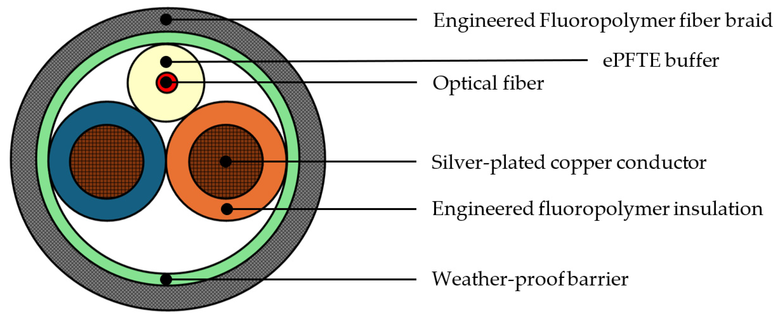
