1. Introduction
With the rapid growth in applications of drones or UAVs in various fields, potential in-flight collisions have become an important safety concern, which can not only damage the drone itself but also endanger the surrounding environment associated with a drone crash. In order to improve drone safety, collision prevention has become a popular research topic, focusing on flight planning, obstacle detection, and obstacle avoidance. In related research, mixed integer linear programming was implemented for both collision avoidance and flight path optimization in [
1]. In [
2], an RGB-D camera was fused with an onboard inertial measurement unit (IMU) to identify static and dynamic obstacles, computing the collision risks and generating escape maneuvers. In [
3], a vision-based obstacle avoidance system was proposed using two fisheye cameras, which utilized a Gaussian-mixture filter to fuse the images from the two cameras, allowing the drone to track multiple neighbours in real time. In [
4], a relaxed-constraint triple integrator planner was proposed, which allowed the drone to maintain safety under the limited field of view by recalling a previously generated motion primitive. In [
5], a causal representation disentanglement module was introduced into a deep reinforcement learning (DRL) framework to address the challenge of collision avoidance for UAVs in a previously unseen environment, which minimized irrelevant factors to improve the generalizability. In [
6], a nonlinear model predictive controller was developed to generate dynamic drone obstacle avoidance maneuvers in real-time, which incorporated the trajectory of the obstacles into optimization. In [
7], the vision-based navigation, control, and obstacle avoidance tasks were formulated as an optimal control problem for drones, which combined with ellipsoidal shaping areas as a safety margin and showed robust obstacle avoidance performance. In [
8], an obstacle-free corridor quadratic program formulation was proposed for real-time path generation of drones through cluttered indoor spaces. While promising, not all drone collisions can be predicted or avoided. When drone collision occurs, drone protection and crash avoidance have become important concerns, so as to reduce the damage to the minimum.
The relevant research works on drone protection can be categorized into passive and active approaches. The passive drone protection approaches focus on modifying the drone frame to reduce the impact during a collision. On the other hand, the active approaches utilize onboard sensors for collision detection and recovery control since recovering quickly from a collision to a steady flight, rather than crashing to the ground, can enhance safety and minimize potential damage.
Regarding passive drone protection, some researchers have used additional cages or guards around the drone to protect them from impacts [
9,
10,
11,
12], and others have employed origami-style designs to absorb impact energy during a collision [
13,
14,
15]. For example, in [
13], an origami-style guard was developed, which will collapse and absorb energy from the impacts upon collision. Besides adding cages or guards, there were also studies that focused on redesigning the drone structure itself to make it more collision-resilient [
16,
17,
18]. For example, in [
16], soft materials were added around the exterior of the drone to improve its impact-absorbing capability. In [
17], more propellers were introduced to create a fully actuated system that is capable of reacting to collisions. In [
18], springs and retractable parts were incorporated into the drone’s arms to reduce the impact upon collision.
The aforementioned passive protection approaches are effective in reducing the damage to the drone itself upon collision. However, the introduction of additional guards, electronics, contraptions, or the redesign of the structure increased the drone’s weight, dimension, and fabrication costs. Moreover, these methods do not address the concern of the drone crashing, which poses a threat to the surrounding environment. In order to address the limitations of passive protection approaches, active collision detection and recovery control approaches provide a promising solution. The active approaches take advantage of onboard sensors for flight control and navigation, such as IMU, to detect collisions [
19,
20], or introduce extra sensors, e.g., hall sensors, for collision detection [
18].
As for the research on IMU-based collision detection, in [
19], fixed thresholds of horizontal acceleration and angular velocities were set for collision detection. In this reported approach, a collision would be flagged when the magnitude of the horizontal acceleration from the onboard IMU exceeds the threshold for acceleration, and the threshold for angular velocity was used to detect the angle of impact [
19]. In [
20], fuzzy logic was implemented to combine the IMU data with the drone’s pre-collision inclination and flipping angles to detect and characterize collisions. In this method, a fixed preset threshold on linear acceleration was used for the detection of a collision [
20]. The approaches reported in [
19,
20] were verified by both simulations and experiments, which demonstrated high success rates for collision detection. While promising, collision detection relying only on a comparison of the IMU data with a preset threshold may flag false alerts when the drone performs aggressive maneuvers, such as rapid turns.
In relation to the research works on collision detection with extra sensors, in [
18], hall sensors were introduced to actively detect the collisions of drones by monitoring their readings. The hall sensor-based approach can effectively distinguish collisions from aggressive maneuvers. However, it requires additional sensors and would require frame modifications, resulting in a more complex setup.
Upon the detection of a collision, recovery control is needed to recover the drone to steady flight. Since the impacts would cause unpredictable disturbances to the drone’s flight, nonlinear control techniques are more suitable for drone recovery than linear ones. For example, the sliding mode control approach has been widely used in many studies on drone recovery control, which was proven to be able to handle sudden external disturbances such as wind gusts and maintain a stable flight through both simulation and physical experiments [
21,
22,
23,
24]. While being effective, sliding mode control techniques may induce oscillations, which could lead to instability in a recovery scenario. In [
25,
26], model predictive control approach was implemented to improve drone tracking performance in complex environments. While promising, the model predictive control approach requires considerable computational power, making it less attractive for recovery control where a quick response is essential.
To address the limitations of the sliding mode control and model predictive control, self-tuning approaches, including fuzzy logic and gain scheduling, are widely used. These self-tuning methods dynamically adapt to the operating conditions and have demonstrated great performance in attitude and altitude control, including short settling times and small overshoots [
27,
28,
29,
30,
31]. Fuzzy logic-based methods are difficult to validate, and the parameters are hard to tune [
32]. Compared to fuzzy logic-based methods and model predictive control, gain scheduling approaches are more suitable for drone recovery control, as they can cover a wider range of operating conditions and are not computationally demanding, although they may require a careful predefinition of the operating conditions.
The main contributions of this work can be summarized as follows:
- ▪
An adaptive collision detection approach was proposed that compares the predicted attitude of the drone with the measured orientation of the onboard IMU using dynamically adjusted thresholds, which can improve the detection accuracy and avoid false or missing alerts under different maneuver conditions.
- ▪
A gain scheduling-based recovery controller was developed that tracks a desired acceleration and orientation of the drone after the impact caused by collision, and adapts its gains to the collision intensity.
- ▪
A comparison study was conducted using simulation tests in ROS Gazebo, and a series of physical experiments were performed with a custom-built quadrotor drone. The simulation and experimental results confirmed the effectiveness of the proposed approaches.
The rest of this paper is organized as follows:
Section 2 presents a dynamic model of the drone under consideration.
Section 3 details the proposed approach in collision detection, characterization, and recovery control.
Section 4 reports the experimental results.
Section 5 provides the conclusion and future research directions.
2. Dynamic Modelling
There are various types of drone frames, including tricopters, quadcopters, and hexacopters, amongst which quadcopters are the most widely used due to their balance of performance [
33,
34,
35]. Without loss of generality, in this paper, the term drone refers to quadcopters. There are two major configurations for quadcopters, the ‘X’ and the ‘+’ configurations, which are defined by the direction and location of the drone’s arms and motors relative to its body frame, as shown in
Figure 1 [
36]. In the ‘+’ configuration, the arms and the motors of the drone align with the X and Y axis of its body frame, whereas in the ‘X’ configuration, the arms and the motors reach out diagonally positioned at a 45-degree angle to the X and Y axis of its body frame. The study in [
37] compared the two configurations with the same drone and found that the ‘X’ configuration provides more stability in maneuvering. In this paper, the drone is modelled in the ‘X’ configuration due to the additional stability.
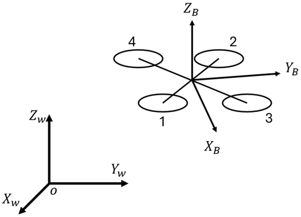
The dynamics of the drone are modelled in the East–North–Up (ENU) convention. The world and body frames are defined as
and
, respectively. For the body frame, the origin is located at the center of the mass of the drone; the positive X-axis is selected to point forward; the positive Z-axis is vertical with the drone frame, pointing upward; and the Y-axis is determined by the right-hand rule, as shown in
Figure 2.
To simplify the modeling process, the following assumptions were made [
38]:
All the propellers and motors are identical, and the dynamic actions are instantaneous;
The drone is assumed to be a rigid body, and the deformation is assumed to be negligible;
The drone is assumed to be able to remain fully functional after collisions, i.e., no structural damage, and all the electronics stay unaffected by the collisions.
The motion of the drone is described using Newton–Euler equations. Let
and
denote the position and the velocity vectors of the drone in the world frame, and let
denote the rotation matrix from the body frame to the world frame.
where
represents the mass of the drone;
denotes the moment of inertia of the drone;
denotes the vector of the angular velocity; and
represents the skew-symmetric matrix of the angular velocity vector
.
is the acceleration vector due to gravity.
and
represent the total thrust and moment acting on the drone, respectively.
The total thrust force
and moment
acting on a drone that is generated by the propellers can be expressed as follows:
where
and
represent the thrust and the drag coefficient of the propellers, respectively;
represents the rotational velocity of the propellers; and the subscript
represents the
specific propeller on the drone.
The control of the drone can be expressed as follows:
where
represents the total thrust;
represent the moments of the x-, y-, and z-axis, respectively; and
l is the distance from the motor to the drone’s center of mass.
3. Collision Detection and Recovery Control
This section presents the proposed collision detection and recovery control approaches.
The proposed collision detection method compares the magnitudes of the expected and actual attitude response in terms of linear acceleration and angular velocity, and the differences are calculated as follows:
where
and
represent the differences in linear acceleration and angular velocity, respectively; the subscript
represents the expected values calculated from the motor speeds; and the subscript “
” represents the measurements from the onboard IMU sensor.
With the assumption that the drone collides with a vertical wall while flying with a small tilt angle, only the horizontal components of the acceleration and angular velocity around the z-axis need to be considered. The expected drone attitudes, the horizontal acceleration and the yaw rate, are derived from the following equations:
where
represents the rotational matrix from the body frame to the world frame.
To compensate for sensor noise and control input delays, a first-order lag filter is implemented:
where
and
denote the outputs at the current and previous sampling time, respectively;
represents the input at the current sampling time; and
is the smoothing factor, ranging from
, and defined as follows:
where
and
represent the time constant and time step, respectively.
The thresholds for collision detection were adjusted dynamically based on the current flight conditions to allow a wider range of collisions to be detected:
where
and
represent the coefficients for thresholds
and
at time t. The two constants
and
are set to mitigate the signal noise, which can cause false detections. The two coefficients,
and
, are determined by the variance in the most recent IMU signals over a sliding window with a size of
samples:
When a collision is detected, the colliding angle and the rotation direction of the drone need to be estimated to enable effective recovery control. The residual horizontal acceleration,
can be calculated with
, and a unit vector that indicate the direction of collision can be obtained by normalizing the residual:
Similarly, the torque direction that induced by the collision can be calculated with the following:
In (19), the sign of the term, , indicates whether the collision introduced a clockwise or counterclockwise torque to the drone around the z-axis. Values of all the terms from Equations (18) and (19) can be measured at the time when a collision is detected.
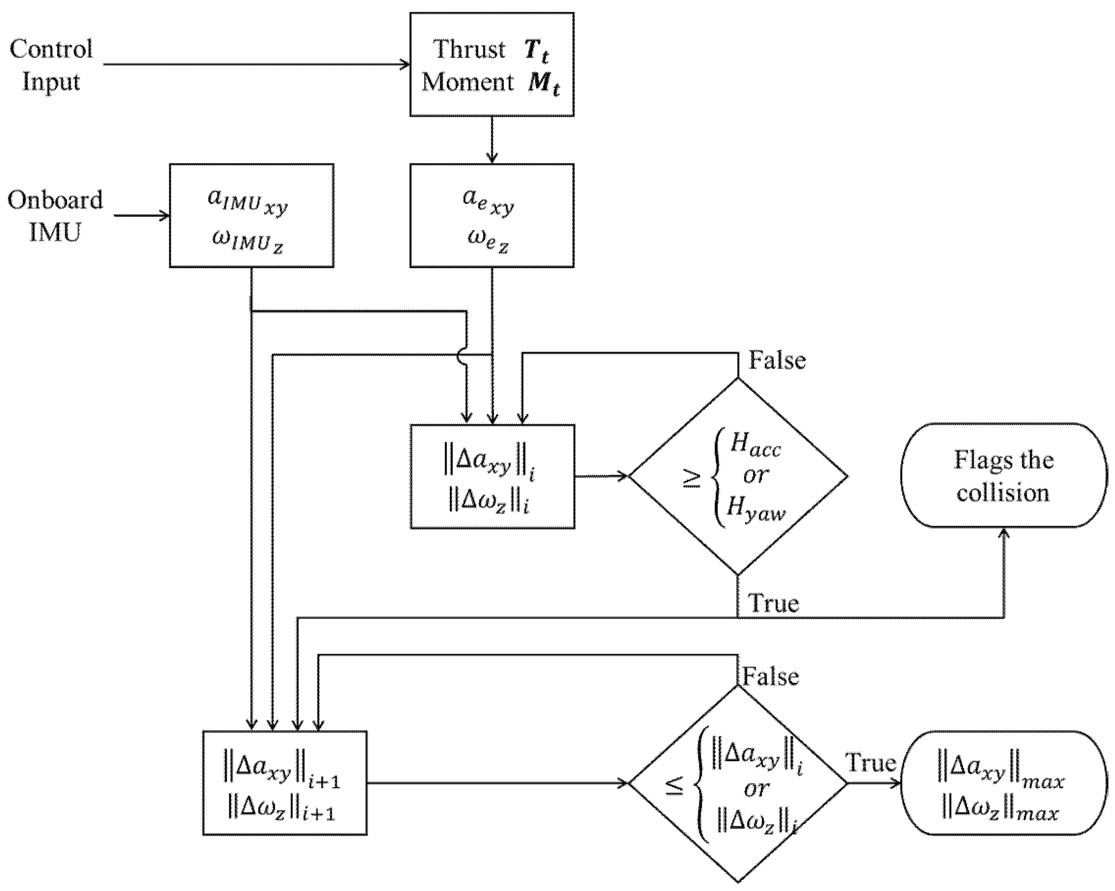
The proposed collision detection and characterization approach is outlined in the flowchart shown in
Figure 3. During each step, the magnitudes of the difference
and
are compared against the thresholds
and
. A collision is flagged if either of the two magnitudes exceeds its corresponding threshold.
Upon detection of a collision, the maximum difference between the calculated and measured attitude response, denoted as
and
, is estimated. The magnitude values calculated at the current time step are compared with the ones obtained from the previous time step until they stop increasing. The estimated maximum difference is used as the level of the intensity, denoted as
in terms of horizontal accelerations and yaw rate, i.e.,
- b.
Recovery Control
The proposed recovery control approach is inspired by the recovery control strategy proposed by Faessler et al. [
39], where the primary objective during the recovery process is to track a desired acceleration and to minimize unwanted yaw movements. In the proposed recovery control approach, the desired acceleration is proportional to the intensity value obtained from the collision characterization process, and the desired yaw rate is selected as zero, i.e.,
where the vector
represents the desired acceleration;
denotes the desired yaw rate; and
represents the proportional gain to scale the desired acceleration based on the intensity of the impact.
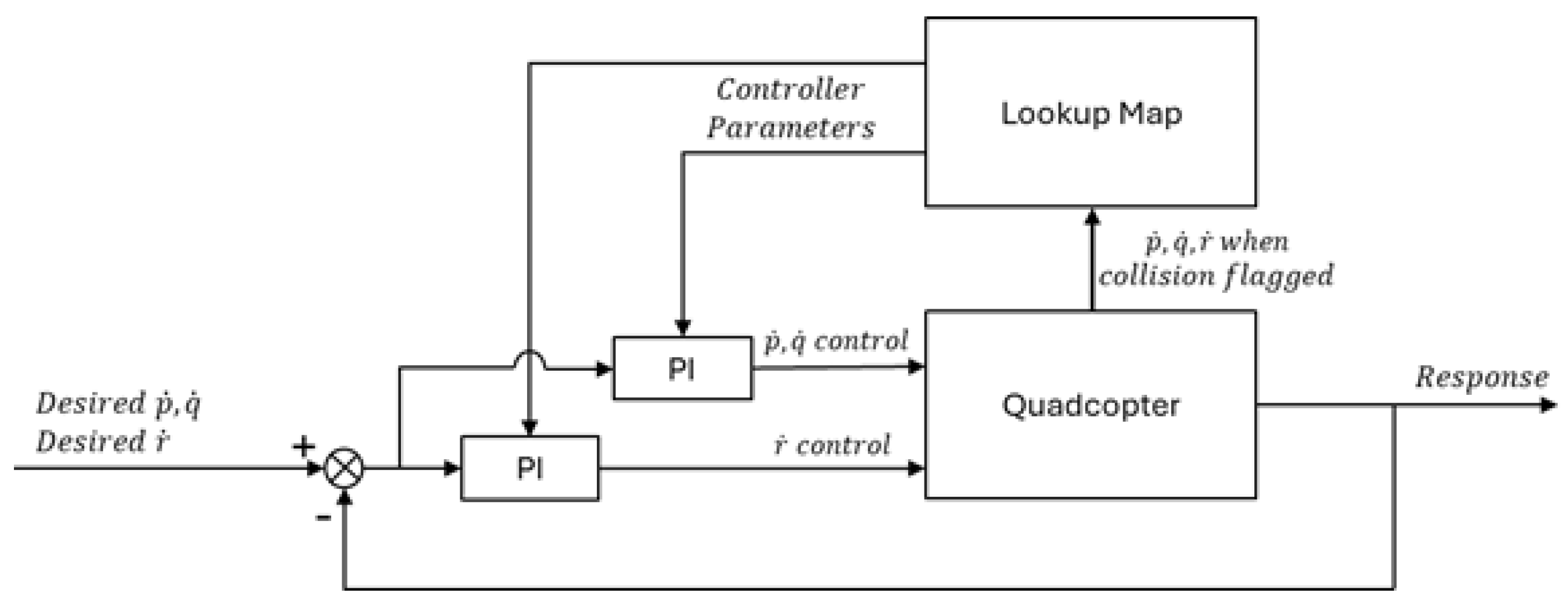
The proposed recovery controller orients the drone to the desired direction and tracks its acceleration by controlling the pitch, roll, and yaw rates, as well as the thrust of the drone. During our simulations and experiments, it was noticed that the drone lost its control faster and started to lose its height earlier with a higher intensity of impact. Thus, it was advisable to have the recovery controller act according to the intensity of the impacts. In other words, high intensity impacts require faster and more aggressive recoveries while impacts with lower intensity could be recovered less aggressively. Furthermore, observation from the simulation studies on collision response indicates that the time from the initial collision to the beginning of the drone crash does not necessarily relate to the peak horizontal acceleration resulting from the impact, while this time duration is more related to the pitch, roll, and yaw rates after the collision. In other words, the higher the rates are, the faster the drone starts to crash. The pitch, roll, and yaw rates are controlled by PI controllers through a gain scheduling technique, as shown in
Figure 4. The maximum magnitude of the pitch/roll rate and the yaw rate after the collision were selected as the scheduling variables.
where
,
and
represent the drone’s pitch, roll, and yaw rates, respectively. The controller was tuned to meet the desired performance at different operating conditions using the gradient descent approach, which was implemented to obtain the suitable parameters for the controller. For a general PI controller that handles the pitch and roll rate control, the cost function
is defined based on the errors in desired performance:
where
and
and
are the parameters of the PI controller.
and
are the settling time and the overshoot percentage and the subscript
represents the desired values. The gradient of the cost function with respect to each parameter can be calculated by the following:
and the gains can be updated by the following:
where
represents the learning rate.
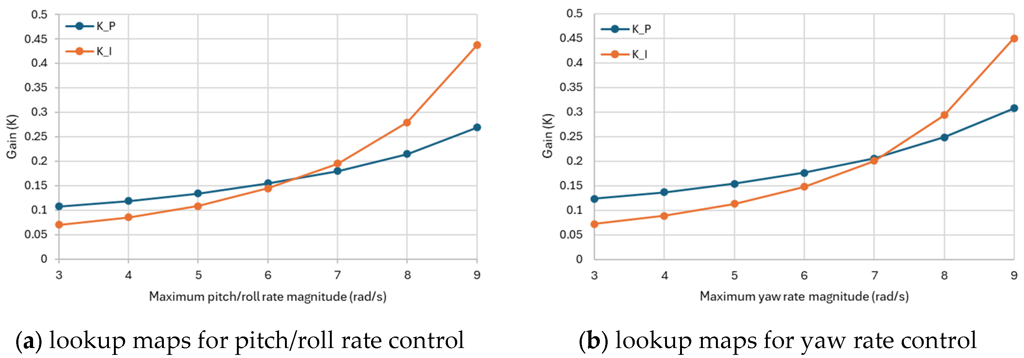
A series of values for the maximum magnitude of the pitch/roll rate after the collision were selected to represent different flight conditions, and for each of the values, the rate controllers are individually tuned. The lookup maps in terms of the desired setting time in this study are shown in
Figure 5. Linear interpolation was used to calculate the parameters of the controllers that fall between the tuned flight conditions.
The pitch and roll rates are also utilized to determine the desired orientation of the drone for recovery after the impact:
where
is a coefficient that is used to determine the desired orientation, and the sign of the coefficient will be determined by comparing the direction
and the direction of the pitch and roll. A maximum magnitude of the desired orientation is typically set at 45° to prevent over-rotation.
4. Simulations and Experiments
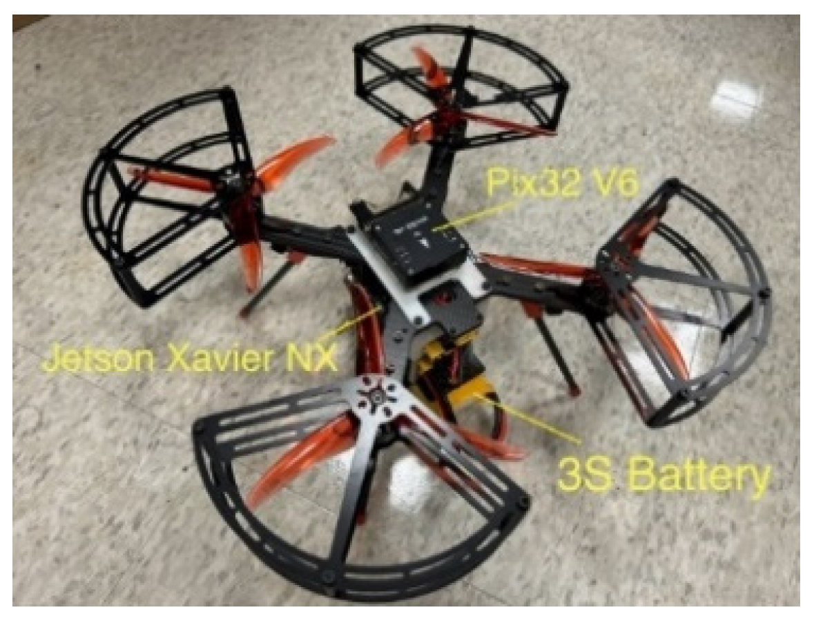
To verify the effectiveness of the proposed collision detection strategy, simulations were conducted in ROS Gazebo to compare the proposed approach with an existing method. To further validate the proposed collision detection and recovery control approaches in the physical world, experiments were conducted in the lab environment using a custom-built quadrotor drone, as shown in
Figure 6. The primary parameters of the drone are listed in
Table 1. During the simulation studies, a detailed 3D model of the drone was created with SolidWorks 2010 and the parameters match the physical drone.
4.1. Comparison Study
The proposed collision detection approach was compared with an existing collision detection method reported in [
16], which triggers a collision when the following applies:
where
is the fixed threshold, as shown in [
16].
The comparison study was conducted in ROS Gazebo with PX4 software-in-the-loop (SITL) in Ubuntu 20.04. A wall was placed in the simulation world on the positive X-axis of the world frame, five meters away from the origin with varying orientations for different scenarios. Fifty Monte Carlo simulation trials were conducted for each scenario. For each trial, the drone started at the origin of the world frame and was commanded to fly along the positive X-axis direction after the takeoff, with a random velocity of up to 2 m/s and hit the wall from different angles. Two collision scenarios were investigated: (a) vertical wall collisions, where the drone flies horizontally into a vertical wall with different inception angles, ranging from 90 degrees (head-on) to 45 degrees, and (b) glancing impacts, where the drone approaches the wall with a shallower angle, which was selected as 10 degrees in this simulation. The glancing impacts would result in a brief bump and an unexpected yaw rotation of the drone. The success rate of the proposed obstacle detection approach was compared with that of the existing method reported in [
16], which was calculated as follows:
The simulation results are summarized in
Table 2 and
Table 3.
Table 2 shows the success rate of detection for each scenario, and
Table 3 presents the average time needed for collision detections. Across all scenarios, both strategies detected impacts in roughly 0.012 s, which is about one timestamp after the collisions. Regarding the detection success rate, the proposed detection strategy successfully identified all fifty vertical wall collisions, outperforming the existing baseline, which missed two collision events. The two missed detections may have been caused by the lower flying velocity, and the IMU signal did not reach the fixed threshold for the existing method. In comparison, the proposed approach introduced adaptive thresholding, which allowed the drone to detect collisions even with subtle impacts. With the more challenging glancing impacts, the proposed method detected 47 collisions, still outperforming the existing method, which only detected 35 impact events.
4.2. Physical Experiment
The drone was powered by a 4000 mAh Li-Po battery and equipped with four 1750 KV motors, and each paired with a three-blade, 3.5-inch propeller. Flight control was handled by an open-source Pixhawk32 V6 flight controller, which estimates the drone’s orientation using signals from an onboard 9-DOF IMU. A Nvidia Jetson Xavier NX GPU module, running Ubuntu 20.04 and ROS software, served as the companion computer to execute the collision detection and recovery algorithms. The Jetson Xavier NX connects with the flight controller and communicates through the MAVLink protocol for collision detection, sending commands for recovery control.
The drone was manually controlled in ‘Stabilized Mode’ from the Pixhawk and switched to ‘Offboard Mode’ only after a collision was detected and during the recovery phase. For safety, a rope was attached to the center of the drone’s frame from above to prevent it from crashing in case of failure. The rope was held slightly to minimize its impact on the flight. The flight data were recorded and saved on the Jetson Xavier NX companion computer for post-experiment analysis.
The test environment was carefully designed, with a hard, solid wood plate placed vertically as a ‘wall’ for the drone to collide with, surrounded by a safety net for additional protection. A total of six test trials were conducted, each preceded by a thorough restart of the collision detection and recovery code to ensure a consistent starting state. During the tests, all of the IMU readings were timestamped when the companion computer received them. The collision detection algorithm also logged a timestamp when a collision was detected. The difference between the timestamps was treated as the time required for detection. During the test, the round-trip delay was identified to be around 5–7 ms.
The physical experiments were conducted with six trials. In the first five trials, the drone collided with the wall at an angle of approximately 90 degrees. The drone was initially placed about 1 m away from the wall for each trial, and it was directed to fly towards the wall after takeoff, with a random velocity of up to 2 m/s and hit the wall from different angles. The velocity of the drone for each trail was recorded, as shown in
Table 4. During the first five trials, the drone’s tilt angle was kept under 15 degrees when approaching the wall before the impacts. Keeping the tilt angle consistent can avoid making additional control adjustments before the impacts, which would help to obtain more reliable experimental results.
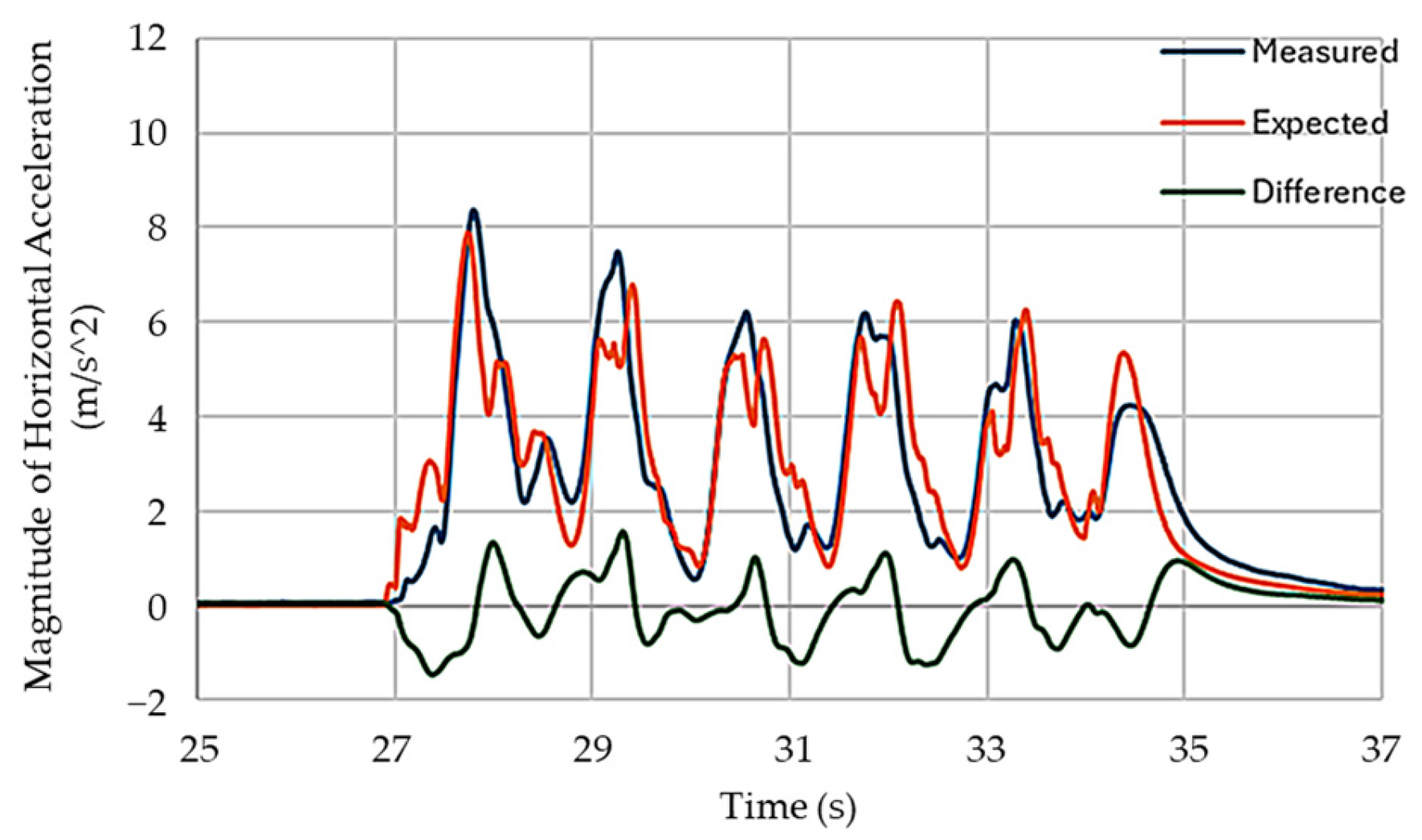
Trial six was conducted with more aggressive flight maneuvers to determine if the proposed approach could distinguish collisions from aggressive maneuvers. In Trial six, the maximum tilt angle and the maximum pitch/roll rate were increased to 70 degrees and 720 deg/s to allow the drone to change direction from left to right rapidly in the air. During the tests, the smoothing factor and time step were selected as .
In the first five trials, the proposed detection approach successfully detected the collisions, and the developed recovery controller managed to recover the drone to stable flight after each collision. Across the five trials, the collision detection algorithm took about 0.032 s to flag a collision, which was a bit slower than in simulations. The longer collision detection time in physical experiments could be due to the latency of communication and onboard computations. During the experiments, the recovery controller effectively reacted to the disturbance and rotation caused by the collision impacts, controlling the drone to move away from the wall.
Figure 7 shows the pitch rate of the drone for all five tests, and
Figure 8 shows the corresponding yaw angles and rates. All the lines plotted in
Figure 7 and
Figure 8 are aligned such that the impact occurs at time t = 0.
In
Figure 7 and
Figure 8, some small oscillations were observed, which may be a result of the drone’s structural vibrations after the impact. From
Figure 7, it can be seen that the drone was able to rotate itself away from the effect after collision detection. From
Figure 8, it can also be seen that the drone stabilized its yaw motion after the collision within 0.2 s. Snapshots of Trial #5 are shown in
Figure 9, illustrating the collision detection and drone recovery process. In this trial, the total time for drone recovery was approximately 0.6 s. The flight control mode switched to ‘Offboard Mode’ 0.08 s after the impact, taking about 0.3 s to reach its desired attitude and another 0.14 s for stabilization.
In the flight test with aggressive maneuver, the magnitude of the measured and expected horizontal acceleration, and the difference with the magnitude of the expected horizontal acceleration,
,
, and
, are plotted in
Figure 10.
The experimental results demonstrated that the drone could successfully detect and recover from collisions using the proposed approaches. The recovery controller effectively reoriented the drone and stabilized it after the impact. It is also demonstrated that the proposed detection method can distinguish between collisions and aggressive flight maneuvers.


