
Method for Multi-Target Wireless Charging for Oil Field Inspection Drones


Abstract
1. Introduction
2. Materials and Methods
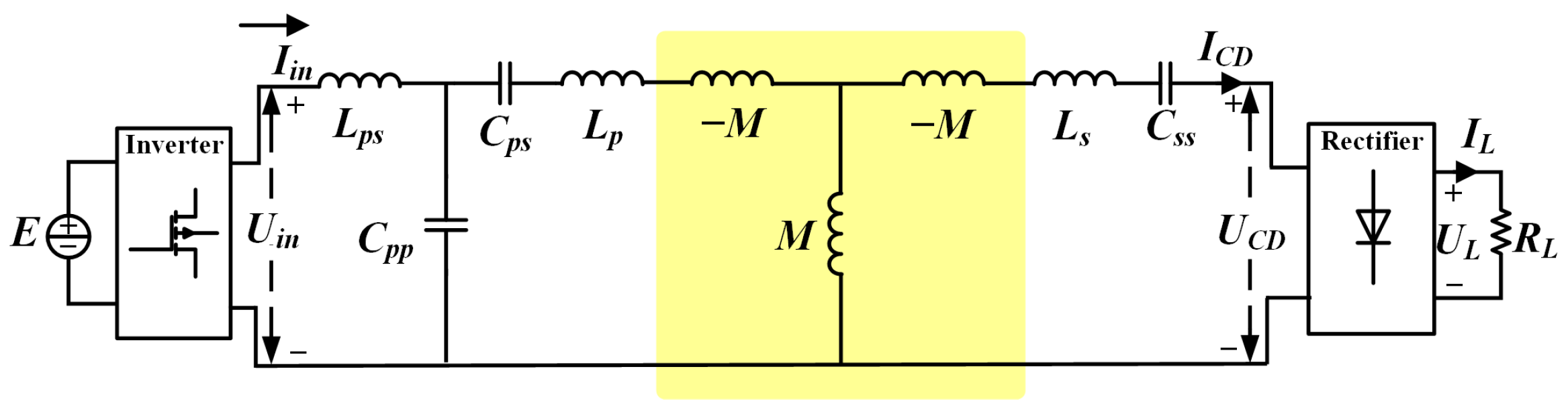
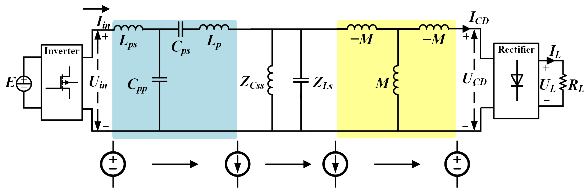
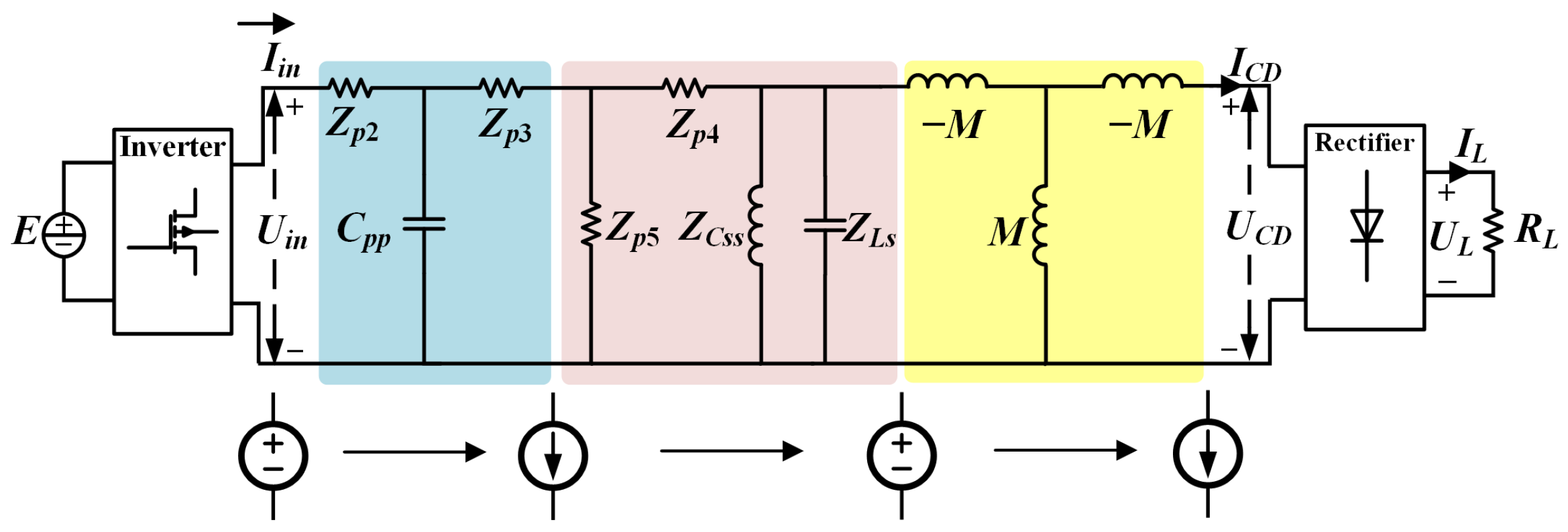
2.1. Theoretical Analysis
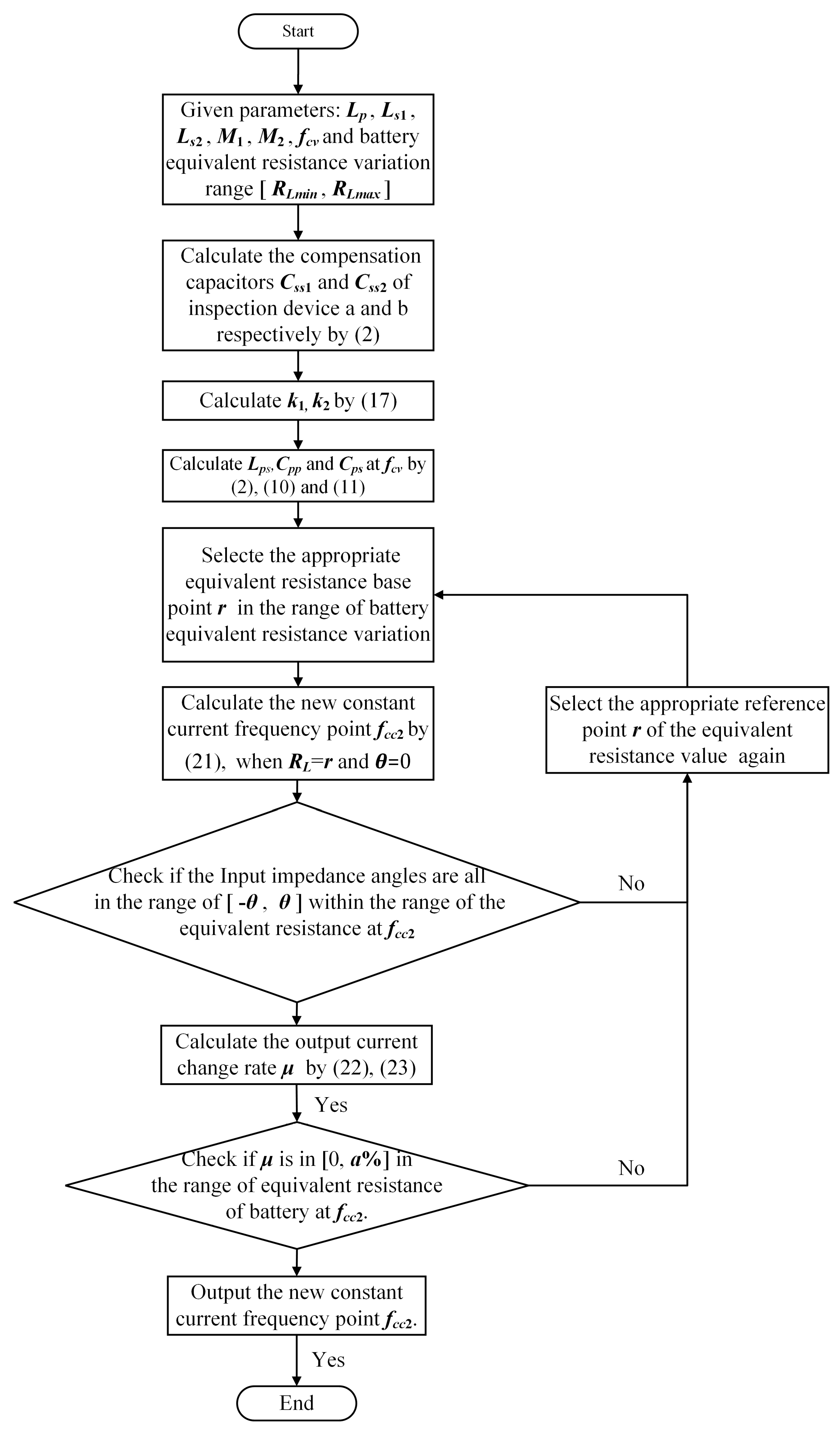
2.2. Parameter Design
3. Results
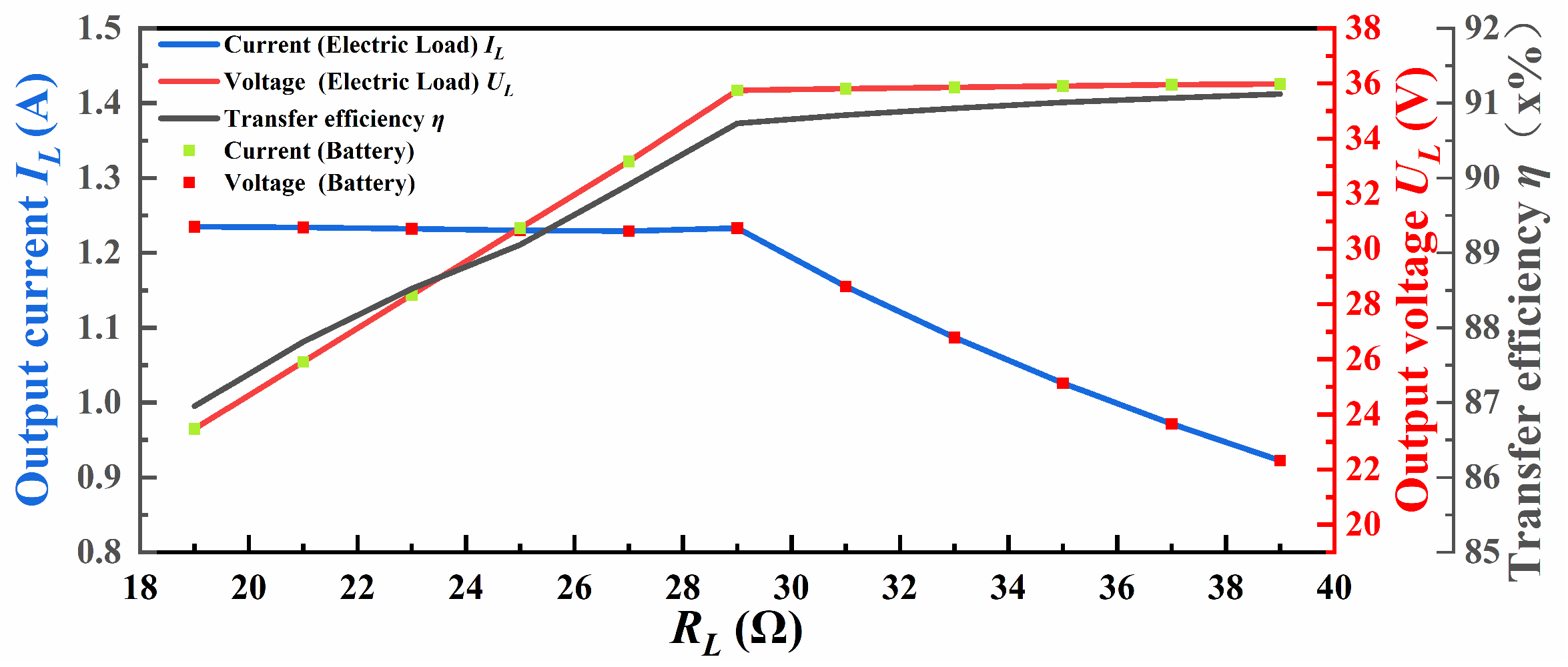
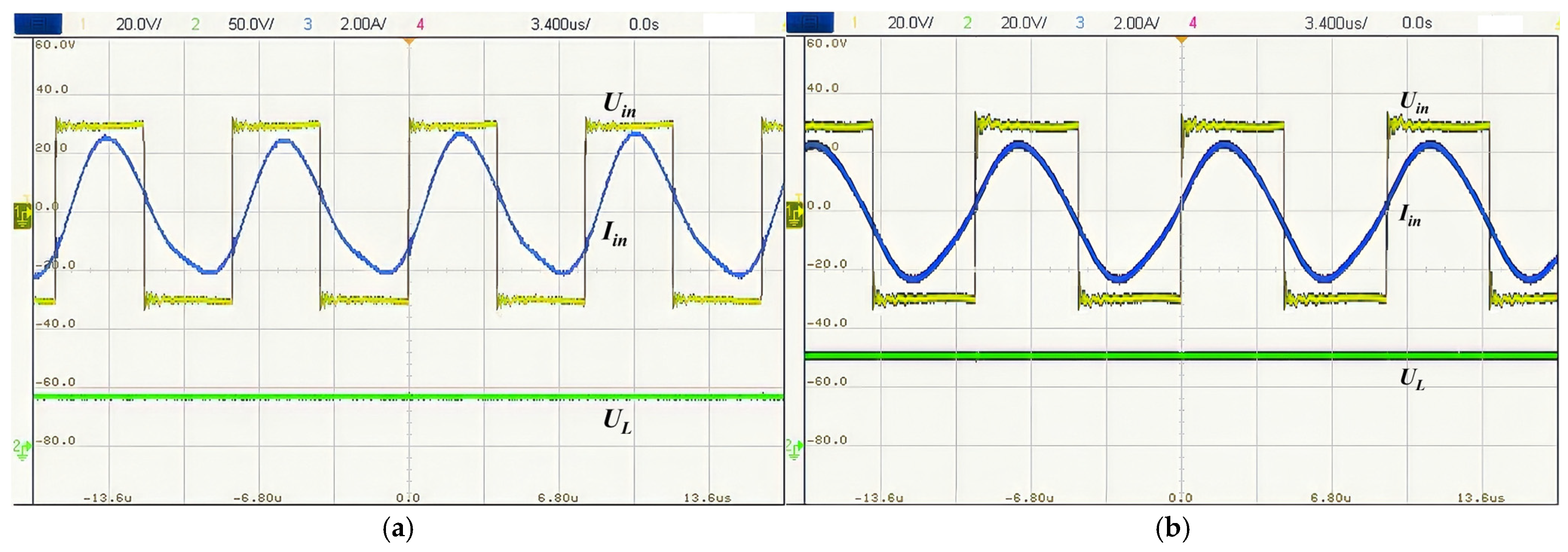
3.1. Inspection Drone A
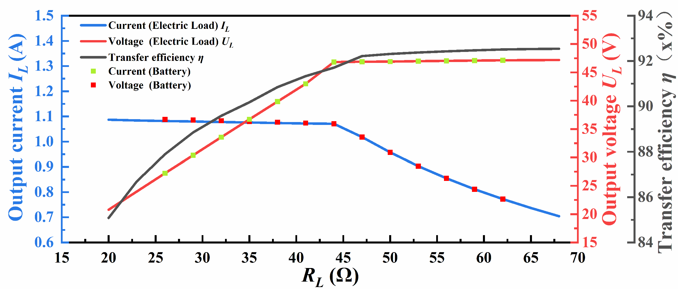
3.2. Inspection Drone B
4. Conclusions
Author Contributions
Funding
Data Availability Statement
Conflicts of Interest
References
- Ahmad, A.; Alam, M.S.; Chabaan, R. A Comprehensive Review of Wireless Charging Technologies for Electric Vehicles. IEEE Trans. Transp. Electrif. 2018, 4, 38–63. [Google Scholar] [CrossRef]
- Li, X.; Wang, H.; Zheng, F.; Dai, X.; Sun, Y.; Hu, A.P. Wireless Charging of Substation Inspection Robots Based on Parameter Estimation Without Communication. IEEE Trans. Circuits Syst. II Express Briefs 2024, 71, 907–911. [Google Scholar] [CrossRef]
- Li, X.; Yu, F.; Madawala, U.K.; Wang, H.; Feng, H.; Dai, X.; Hu, J. A Dual-Coupled Double-LCC System with the Capability of Misalignment Tolerance Improvement for Wireless Charging Substation Inspection Robots. IEEE Trans. Power Electron. 2024, 39, 6624–6629. [Google Scholar] [CrossRef]
- Zhang, Z.; Pang, H.; Georgiadis, A.; Cecati, C. Wireless Power Transfer—An Overview. IEEE Trans. Ind. Electron. 2019, 66, 1044–1058. [Google Scholar] [CrossRef]
- Hu, J.; Zhao, J.; Cui, C. A Wide Charging Range Wireless Power Transfer Control System with Harmonic Current to Estimate the Coupling Coefficient. IEEE Trans. Power Electron. 2021, 36, 5082–5094. [Google Scholar] [CrossRef]
- Ramezani, A.; Narimani, M. Optimized Electric Vehicle Wireless Chargers with Reduced Output Voltage Sensitivity to Misalignment. IEEE J. Emerg. Sel. Top. Power Electron. 2020, 8, 3569–3581. [Google Scholar] [CrossRef]
- Tran, D.H.; Vu, V.B.; Choi, W. Design of a High-Efficiency Wireless Power Transfer System with Intermediate Coils for the On-Board Chargers of Electric Vehicles. IEEE Trans. Power Electron. 2018, 33, 175–187. [Google Scholar] [CrossRef]
- Zheng, C.; Lai, J.S.; Chen, R.; Faraci, W.E.; Zahid, Z.U.; Gu, B.; Zhang, L.; Lisi, G.; Anderson, D. High-Efficiency Contactless Power Transfer System for Electric Vehicle Battery Charging Application. IEEE J. Emerg. Sel. Top. Power Electron. 2015, 3, 65–74. [Google Scholar] [CrossRef]
- Vu, V.B.; Tran, D.H.; Choi, W. Implementation of the Constant Current and Constant Voltage Charge of Inductive Power Transfer Systems with the Double-Sided LCC Compensation Topology for Electric Vehicle Battery Charge Applications. IEEE Trans. Power Electron. 2018, 33, 7398–7410. [Google Scholar] [CrossRef]
- Barmada, S.; Musolino, A.; Zhu, J.; Yang, S. A Novel Coil Architecture for Interoperability and Tolerance to Misalignment in Electric Vehicle WPT. IEEE Trans. Magn. 2023, 59, 8600205. [Google Scholar] [CrossRef]
- Song, K.; Lan, Y.; Zhang, X.; Jiang, J.; Sun, C.; Yang, G.; Yang, F.; Lan, H. A Review on Interoperability of Wireless Charging Systems for Electric Vehicles. Energies 2023, 16, 1653. [Google Scholar] [CrossRef]
- Zhang, Y.; Shen, Z.; Liu, C.; Mao, X.; Zhuang, Y.; Chen, S.; Tang, Y. A Quadrupole Receiving Coil with Series-Connected Diode Rectifiers for Interoperability of Nonpolarized and Polarized Transmitting Coils. IEEE Trans. Power Electron. 2023, 38, 8000–8004. [Google Scholar] [CrossRef]
- Kim, S.; Covic, G.A.; Boys, J.T. Tripolar Pad for Inductive Power Transfer Systems for EV Charging. IEEE Trans. Power Electron. 2017, 32, 5045–5057. [Google Scholar] [CrossRef]
- Hou, J.; Chen, Q.; Zhang, Z.; Wong, S.C.; Tse, C.K. Analysis of Output Current Characteristics for Higher Order Primary Compensation in Inductive Power Transfer Systems. IEEE Trans. Power Electron. 2018, 33, 6807–6821. [Google Scholar] [CrossRef]
- Mou, X.; Gladwin, D.; Jiang, J.; Li, K.; Yang, Z. Near-Field Wireless Power Transfer Technology for Unmanned Aerial Vehicles: A Systematical Review. IEEE J. Emerg. Sel. Top. Ind. Electron. 2023, 4, 147–158. [Google Scholar] [CrossRef]
- Chittoor, P.K.; Chokkalingam, B.; Mihet-Popa, L. A Review on UAV Wireless Charging: Fundamentals, Applications, Charging Techniques and Standards. IEEE Access 2021, 9, 69235–69266. [Google Scholar] [CrossRef]
- Li, D.; Wu, X.; Gao, W.; Gao, J. Multi-mode joint modulation of array wireless power transfer. Sci. Rep. 2023, 13, 15780. [Google Scholar] [CrossRef]
- Zhang, Y.; Yan, Z.; Kan, T.; Liu, Y.; Mi, C.C. Modelling and analysis of the distortion of strongly-coupled wireless power transfer systems with SS and LCC–LCC compensations. IET Power Electron. 2019, 12, 1321–1328. [Google Scholar] [CrossRef]
- Zhu, Y.; Wu, H.; Li, F.; Zhu, Y.; Pei, Y.; Liu, W. A Comparative Analysis of S-S and LCCL-S Compensation for Wireless Power Transfer with a Wide Range Load Variation. Electronics 2022, 11, 420. [Google Scholar] [CrossRef]
- Balcells, J.; Santolaria, A.; Orlandi, A.; Gonzalez, D.; Gago, J. EMI reduction in switched power converters using frequency Modulation techniques. IEEE Trans. Electromagn. Compat. 2005, 47, 569–576. [Google Scholar] [CrossRef]
- Pan, W.; Liu, C.; Tang, H.; Zhuang, Y.; Zhang, Y. An Interoperable Electric Vehicle Wireless Charging System Based on Mutually Spliced Double-D Coil. IEEE Trans. Power Electron. 2023, 39, 3864–3872. [Google Scholar] [CrossRef]
- Cai, C.; Wang, J.; Saeedifard, M.; Zhang, P.; Chen, R.; Zhang, J. Gyrator-Gain Variable WPT Topology for MC-Unconstrained CC Output Customization Using Simplified Capacitance Tuning. IEEE Trans. Ind. Electron. 2024, 71, 3594–3605. [Google Scholar] [CrossRef]
- Steigerwald, R.L. A comparison of half-bridge resonant converter topologies. IEEE Trans. Power Electron. 1988, 3, 174–182. [Google Scholar] [CrossRef]
- Wang, W.; Deng, J.; Chen, D.; Wang, Z.; Wang, S. A Novel Design Method of LCC-S Compensated Inductive Power Transfer System Combining Constant Current and Constant Voltage Mode via Frequency Switching. IEEE Access 2021, 9, 117244–117256. [Google Scholar] [CrossRef]
- Skorvaga, J.; Pavelek, M. Comparison of 3D models of the circular and square coupling coils for WPT with power 44kW. In Proceedings of the 2022 ELEKTRO (ELEKTRO), Krakow, Poland, 23–26 May 2022; pp. 1–6. [Google Scholar]
- Luo, Z.; Wei, X. Analysis of Square and Circular Planar Spiral Coils in Wireless Power Transfer System for Electric Vehicles. IEEE Trans. Ind. Electron. 2018, 65, 331–341. [Google Scholar] [CrossRef]
- Galimov, M.; Fedorenko, R.; Klimchik, A. UAV Positioning Mechanisms in Landing Stations: Classification and Engineering Design Review. Sensors 2020, 20, 3648. [Google Scholar] [CrossRef]
- Ji, L.; Zhang, M.; Qian, B.; Sun, H. A Series of Hybrid WPT Systems with Automatic Switching Between Constant-Current and Constant-Voltage Modes on the Secondary Side. IEEE J. Emerg. Sel. Top. Power Electron. 2023, 11, 361–371. [Google Scholar] [CrossRef]


| Parameter | Value | Parameter | Value |
|---|---|---|---|
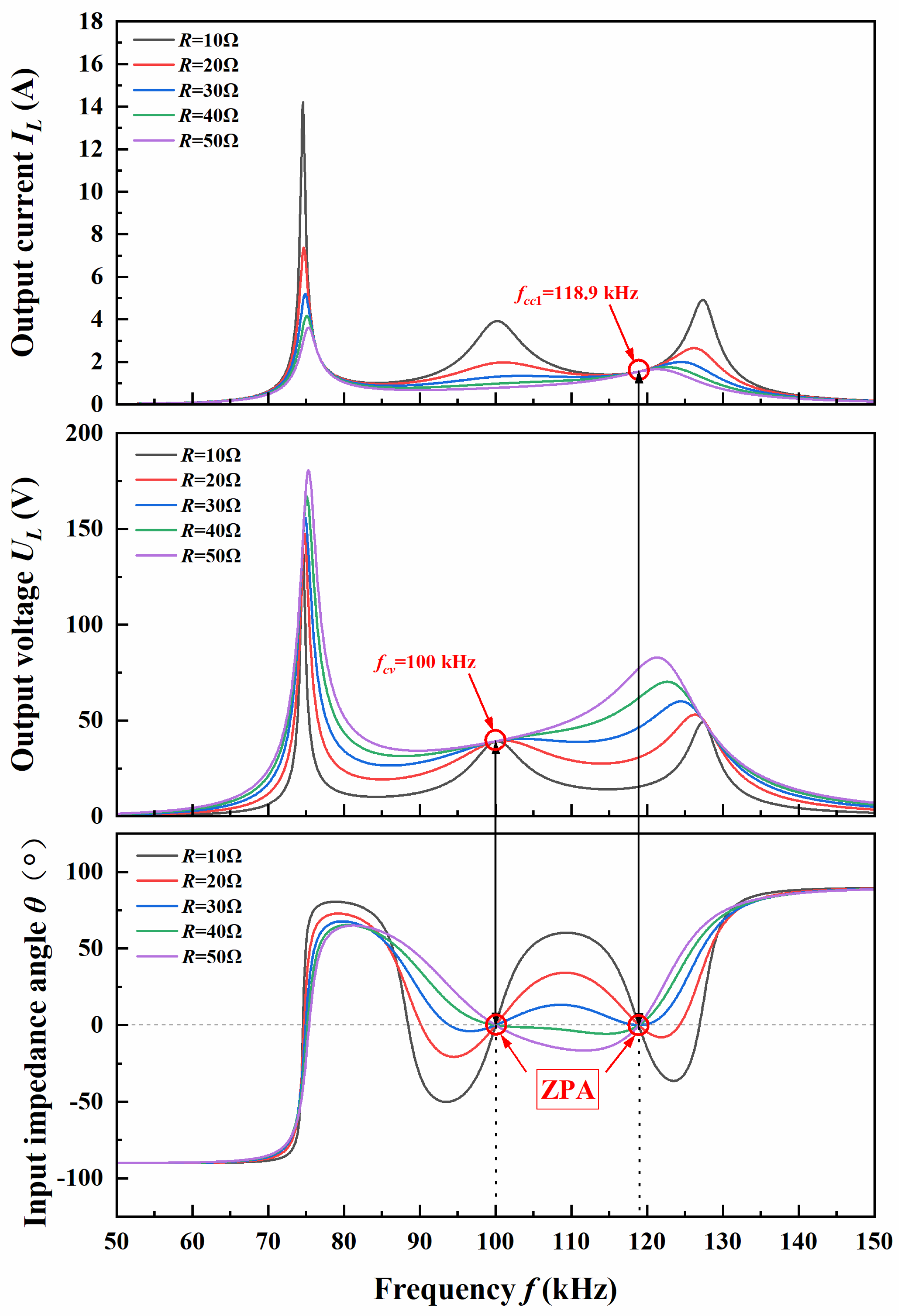
| Lp | 281.12 μH | fcv | 100 kHz |
| Ls1 | 163.774 μH | fcc1 | 118.9 kHz |
| Ls2 | 242.044 μH | fcc2 | 121.323 kHz |
| M1 | 62.79 μH | Lps | 48.116 μH |
| M2 k | 80.939 μH 0.2926 | Css1 Css2 | 15.467 nF 10.465 nF |
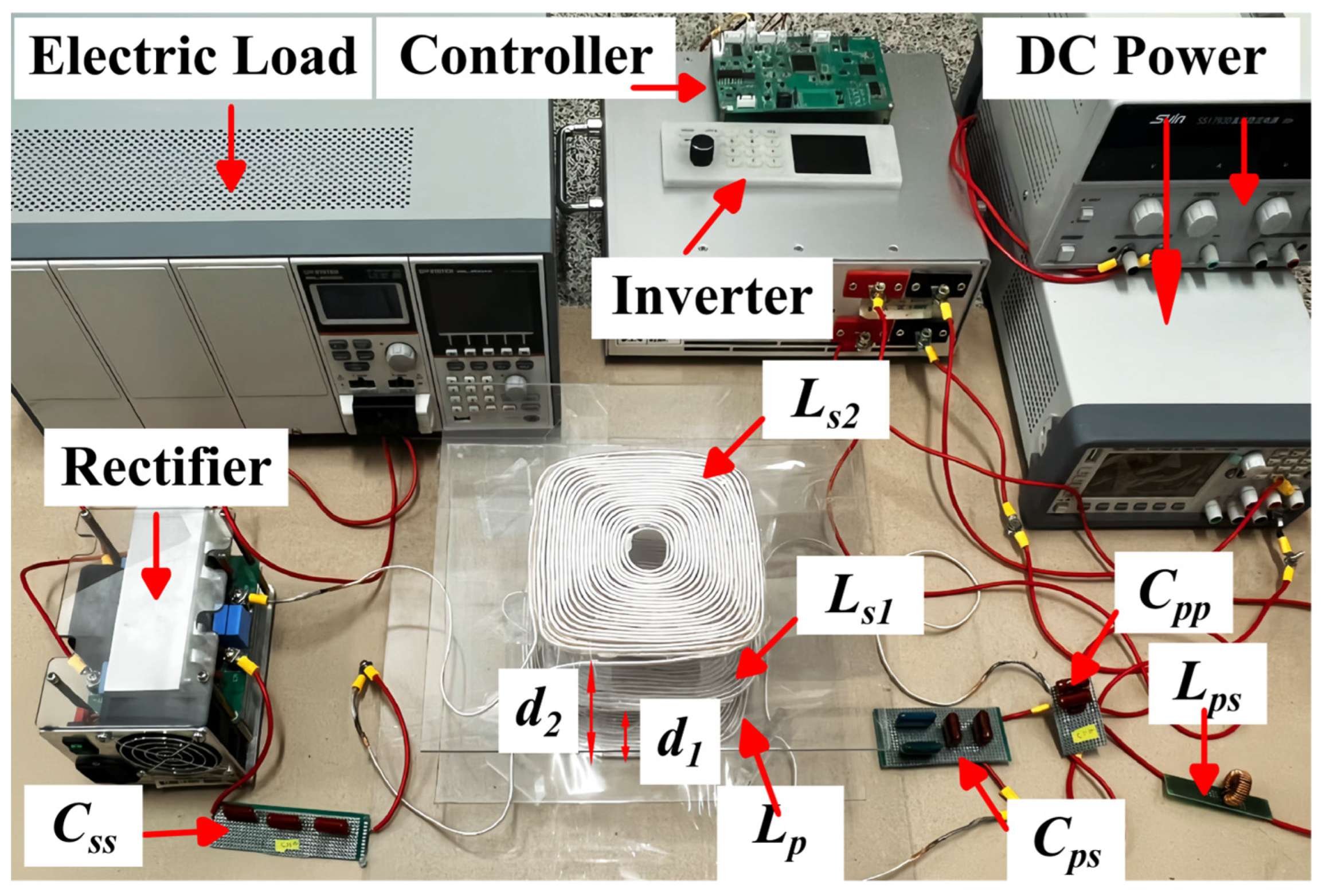
| Cpp d1 | 52.644 nF 5 cm | Cps d2 | 10.871 nF 8 cm |
| Ref (Year) | Nominal Gap | Output Voltage | CC/CV Reg. | Peak Eff. | CC/CV Method | Freq. (kHz) | Supports Multi-Target? |
|---|---|---|---|---|---|---|---|
| Vu et al. (2018) [9] | ~15 cm | ~400 V (EV battery) | CC and CV | ~92% (coils) | Double-sided LCC topology | 85 (fixed) | ✖ No (single fixed load) |
| Ramezani et al. (2020) [6] | 15 cm | ~400 V (CV only) | CV only | ~90% | Passive LCC tuning | 85 (fixed) | ✖ No |
| Hu et al. (2021) [5] | 10–25 cm | N/A | Adaptive only | ~88% | Harmonic-based duty control | 85 (fixed) | ✖ No |
| Galimov et al. (2020) [27] | ~15 cm | ~400 V | CC and CV | 97.3% | Frequency switching (LCC-S) | 85/105 | ✖ No |
| Ji et al. (2023) [28] | ~8 cm | ~30 V | CC and CV | ~90% | Hybrid switching (relay) | 100 (fixed) | ✔ Yes (hardware switch) |
| Li et al. (2024) [3] | ~10 cm | ~5 V | CV | ~94% | Dual-LCC network | 85 (fixed) | ✖ No |
| Luo et al. (2018) [26] | 5–15 cm | (CC only) | CC only | ~90% | Cap tuning only | 85 (fixed) | ✖ No |
| This work | 5–8 cm | 23–47 V | CC and CV | 92.3% | Frequency regulation only | 100–121.3 | ✔ Yes (multi-drone adaptive) |
Disclaimer/Publisher’s Note: The statements, opinions and data contained in all publications are solely those of the individual author(s) and contributor(s) and not of MDPI and/or the editor(s). MDPI and/or the editor(s) disclaim responsibility for any injury to people or property resulting from any ideas, methods, instructions or products referred to in the content. |
© 2025 by the authors. Licensee MDPI, Basel, Switzerland. This article is an open access article distributed under the terms and conditions of the Creative Commons Attribution (CC BY) license (https://creativecommons.org/licenses/by/4.0/).
Share and Cite
Wang, Y.; Ji, L.; Zhang, M. Method for Multi-Target Wireless Charging for Oil Field Inspection Drones. Drones 2025, 9, 381. https://doi.org/10.3390/drones9050381
Wang Y, Ji L, Zhang M. Method for Multi-Target Wireless Charging for Oil Field Inspection Drones. Drones. 2025; 9(5):381. https://doi.org/10.3390/drones9050381
Chicago/Turabian StyleWang, Yilong, Li Ji, and Ming Zhang. 2025. "Method for Multi-Target Wireless Charging for Oil Field Inspection Drones" Drones 9, no. 5: 381. https://doi.org/10.3390/drones9050381
APA StyleWang, Y., Ji, L., & Zhang, M. (2025). Method for Multi-Target Wireless Charging for Oil Field Inspection Drones. Drones, 9(5), 381. https://doi.org/10.3390/drones9050381