1. Introduction
Urban Air Mobility (UAM) not only alleviates ground traffic congestion but also offers a more efficient and environmentally friendly mode of transportation for high-density urban areas, demonstrating tremendous market potential [
1,
2]. With the growing demand for Urban Air Mobility [
3], particularly in areas such as emergency response, cargo transportation, and passenger travel, the need for efficient, flexible, and sustainable transportation solutions is becoming increasingly urgent [
4]. This trend has accelerated the rapid development of vertical take-off and landing (VTOL) aircraft technologies; particularly, the distributed electric tilt-rotor UAV enables flexible vertical take-off and landing as well as efficient cruising without reliance on large-scale infrastructure [
5]. Joby Aviation has achieved substantial technological advancements in this field; its developed electric vertical take-off and landing (eVTOL) aircraft has undergone multiple flight tests and demonstrated promising performance [
6].
Figure 1 shows a pre-production prototype of the Joby electric tilt-rotor VTOL aircraft. In addition, the application of the Distributed Electric Propulsion (DEP) concept is expected to reduce operating costs and noise pollution, positioning the distributed electric tilt-rotor UAV as one of the key technologies for UAM and future aviation systems [
7].
The multi-rotor system features multiple power sources, and by adding more rotors, the lift can be evenly distributed across the propulsion units, reducing the load on each individual rotor and enhancing the overall thrust performance of the system [
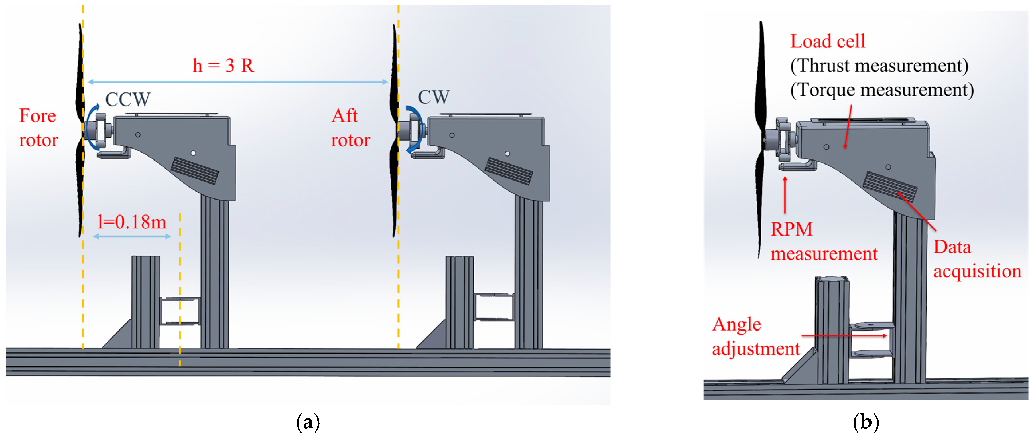
8]. In tilt-rotor systems, a tandem configuration refers to the arrangement in which multiple rotors or tilt-wings are positioned at a defined axial spacing—specifically, the longitudinal distance along the fuselage between the centers of the fore and aft rotor disks. In such configurations, the fore and aft rotors (or tilt-wings) operate independently, each contributing to the generation of lift, thrust, and control moments. The tandem configuration allows for greater lift and thrust within a more compact airframe. However, this configuration introduces complex aerodynamic interactions between the rotors [
9], as well as significant aerodynamic interference caused by the relative positioning of the rotors and wings [
10]. These issues can adversely affect the aircraft’s control capabilities, especially when the rotor spacing is close and the transition between vertical and horizontal flight modes is not synchronized. These interactions can significantly affect the aerodynamic performance and operational efficiency of the aircraft, particularly in typical low-speed, high-lift operating environments such as urban settings [
11]. They also impose greater demands on the structural design and flight control system design of tilt-rotor aircraft [
12]. Therefore, optimizing the aerodynamic performance of the tilt tandem rotor propulsion system to improve overall flight efficiency and stability has become a new challenge in the performance optimization design of distributed electric tilt-rotor aircraft.
With the rapid development of computer technology, computational fluid dynamics (CFD) methods have gained significant attention and are widely used in the aerodynamic performance analysis of multi-rotor systems, tilt-rotor systems, and eVTOL aircraft due to their ability to accurately capture flow field characteristics. CFD technology provides a low-cost and flexible tool for analyzing the aerodynamic characteristics of tilt-rotor UAVs. Ye [
13] developed a rotor CFD solver capable of effectively simulating the flow field and aerodynamic characteristics of tilt-rotor aircraft in hover conditions. Sheng [
14] employed a CFD solver to predict and analyze the unsteady flow field and aerodynamic performance of a wind tunnel test model of the Bell Boeing quad tilt-rotor aircraft. The results indicated that aerodynamic interference and periodic time-varying loads occur among the fore and aft rotors and the wing system under different flight conditions. Although CFD plays a vital role in the aerodynamic performance analysis of UAVs, the computational accuracy and stability of existing CFD models still need further improvement under certain flight conditions and configurations. In addition, to ensure the reliability of CFD predictions, validation with experimental data remains necessary [
15].
In terms of experimental research, as early as 1954, Dingeldein [
16] conducted a series of wind tunnel experiments on both tandem and coaxial configurations, yielding valuable experimental data. When overlap exists between tandem rotors and the axial spacing is limited, it becomes particularly important to measure the performance characteristics of the fore and aft rotors. Zanotti et al. [
17] conducted a series of wind tunnel experiments to investigate the impact of varying overlap between two tandem propellers on rotor performance and the aerodynamic interactions within the flow field. The results showed that as the overlap between the rotor disks increased, the aft rotor experienced a significant loss in thrust. Ramasamy [
18] was the first to estimate the aerodynamic interference loss factor by comparing thrust and hover efficiency among tandem configurations (with torque balance), tiltrotor systems, and single-rotor systems, all having the same solidity (i.e., the same rotor blade area fraction). The estimation is applicable over a wide range of lateral spacing. Yang [
19] investigated the aerodynamic performance of small-scale rotors in tilted transition states through wind tunnel testing and found that the thrust coefficient increases with the Reynolds number but decreases with advancing ratios. Shukla [
20] measured a set of side-by-side rotors in hover over a range of rotor separations and explored rotor wake behavior under different axial spacings and two distinct Reynolds numbers using high-speed stereo particle image velocimetry (SPIV), assessing the impact of rotor spacing on performance. While the above experimental and simulation studies have explored the effects of rotor spacing, advance ratio, and Reynolds number on aerodynamic performance, they primarily focus on helicopter mode and have not accounted for aerodynamic interactions during asynchronous transitions between fore and aft rotors, where asynchronous transition refers to the condition in which the fore and aft rotors tilt at different times rather than simultaneously. There is a lack of aerodynamic performance evaluation for tilt multi-rotor systems under dynamic transitional flight conditions. Therefore, investigating the influence of parameters such as rotor tilt angle and rotational speed on flight performance is of great significance for optimizing the design of tilt-rotor UAVs.
In recent years, researchers around the world have conducted extensive studies on tandem rotor systems. Zanotti [
21] investigated the effects of parameters such as tilt angle and lateral spacing on the performance of dual-rotor systems. Ramasamy [
22] conducted tests on the hover performance of tandem rotors. Celik [
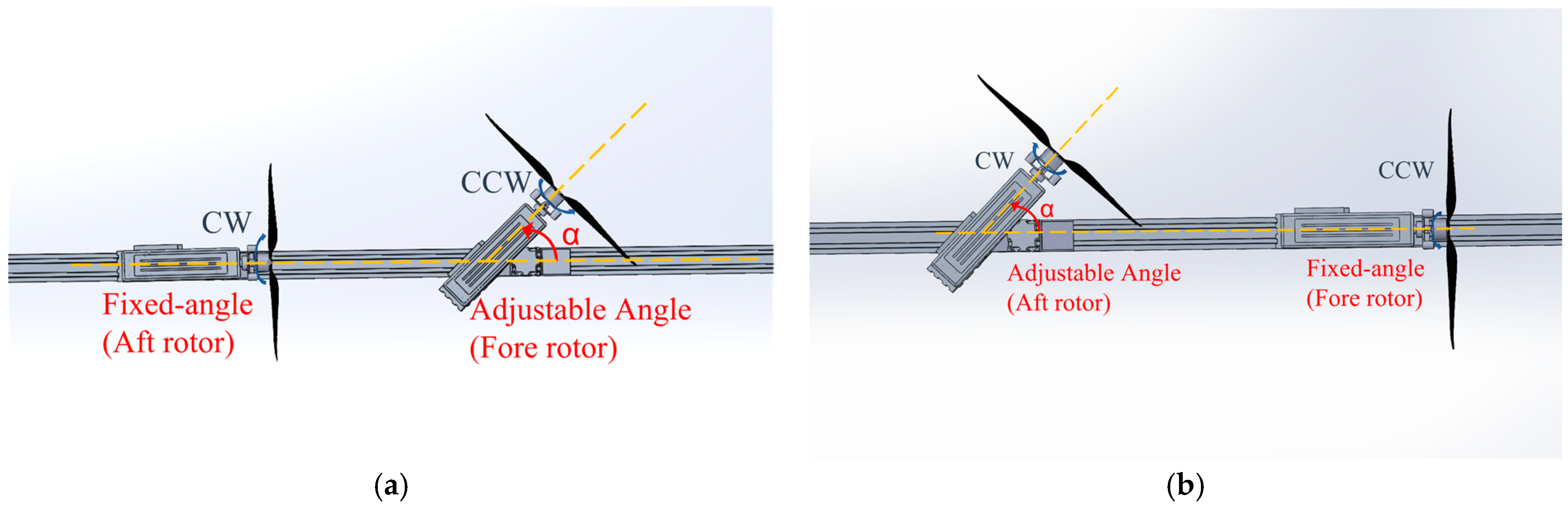
23] explored the aerodynamic noise of tandem rotors. Asynchronous tilt-rotor configurations for the distributed electric tilt-rotor UAVs are also a promising option. However, most of the current research focuses on synchronized tilt tandem dual-rotor configurations, with limited studies on the aerodynamic performance of tandem rotor systems in asynchronous tilt states. Therefore, this paper primarily investigates the changes in aerodynamic performance of the tandem dual-rotor system in the asynchronous transition process of the tilt-rotor UAV. Using a custom-designed aerodynamic performance testing platform for tilt dual-rotor systems, the study measured performance indicators such as thrust, torque, and power variations with changes in rotor tilt angle and rotational speed for a reverse rotating rotor model with fixed axial distance. Additionally, the impact of aerodynamic interactions between the fore and aft rotor disks on the multi-rotor system’s performance was analyzed. It should be noted that due to the varying incoming flow velocities for rotors at different tilt angles in the forward flight state, conducting an experimental design is challenging. However, the influence of tilt angle on the aerodynamic forces of the tandem rotor system without incoming flow remains of significant reference value. Therefore, the entire experimental process was conducted under no incoming flow conditions.
First, this paper introduces the experimental setup and its measurement principles, outlining the fundamental design considerations of the experiment. Subsequently, after validating the accuracy of the testing platform, relevant experiments were conducted, and the results were analyzed and discussed. Finally, conclusions are presented based on the above research and analysis.
3. Results and Discussion
First, the performance of the fore and aft rotors without mutual interference was analyzed to verify whether the measured thrust values aligned with theoretical predictions. Next, for the two asynchronous tilt conditions—namely, the forward rotor tilting with the aft rotor fixed, and the aft rotor tilting with the forward rotor fixed—the effects of tilt angle and rotor speed on aerodynamic performance metrics such as thrust, power, and torque were evaluated. Finally, based on the independently measured rotor performance data, a comparative analysis was conducted across different configurations at commonly used rotational speeds to identify the tilt scheme that offers superior aerodynamic performance in tandem rotor systems.
To more clearly illustrate the aerodynamic performance losses caused by rotor-to-rotor interference, two performance variation indicators are defined and introduced for the analysis of the experimental results: thrust variation rate AT and power variation rate AP. These are defined as follows:
Here, T and P represent the rotor thrust and power under the corresponding test conditions, while TS and PS denote the thrust and power measured under non-interference (independent rotor) conditions.
3.1. Isolated Rotor Performance
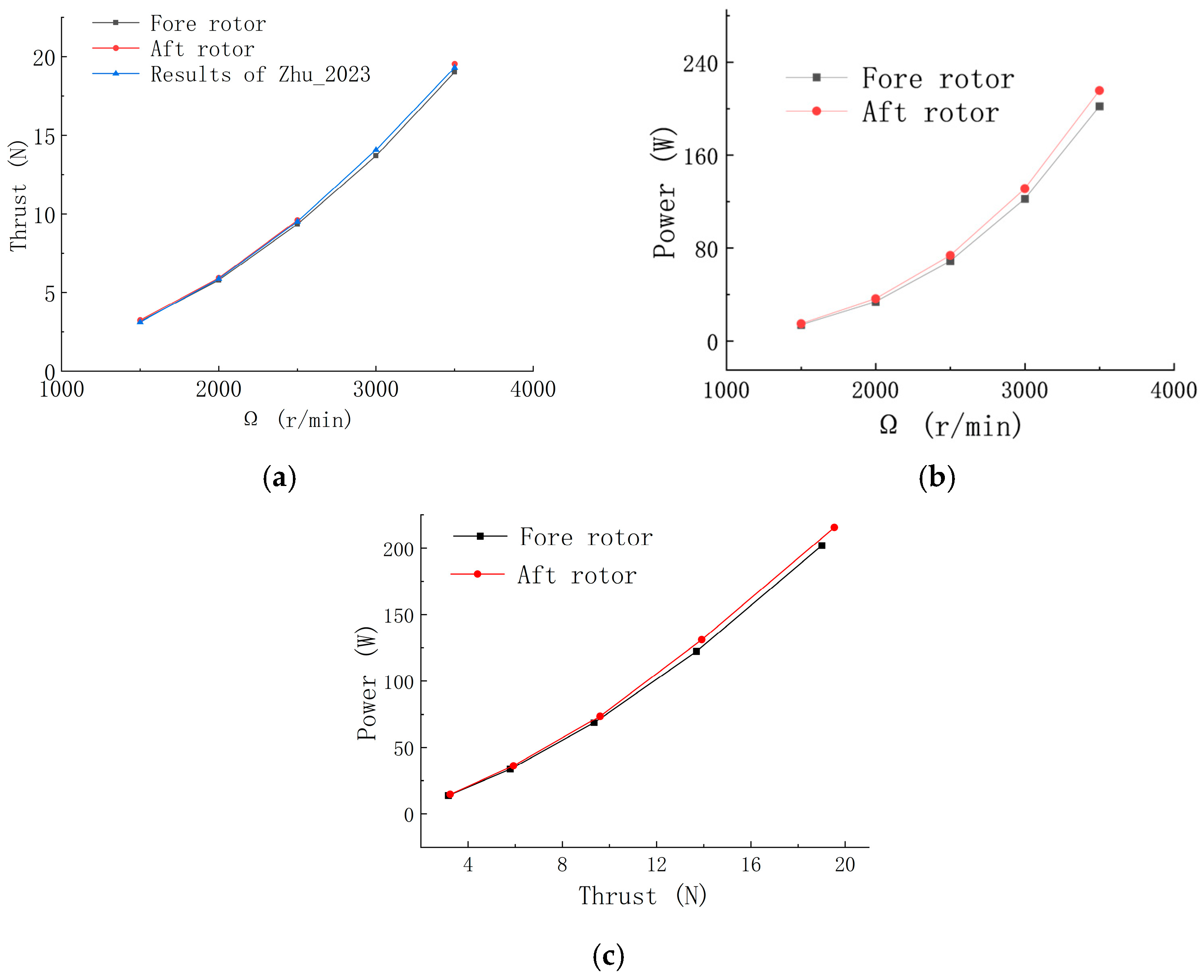
Before conducting the formal performance tests of the tandem tilt counter-rotating rotor system, independent performance tests were carried out on both the fore and aft rotors under non-interference conditions. The measured thrust results were validated against theoretical predictions to ensure that the errors introduced by the test rigs for the fore and aft rotors remained within an acceptable range. The independently measured thrust results for the fore and aft rotors are shown in
Figure 4. The theoretical formula for rotor thrust [
25] is given as follows:
Here, ρ is the air density, Ω is the rotor angular velocity, R is the rotor radius, and CT is the thrust coefficient. According to the equation, rotor thrust increases monotonically in a parabolic manner with respect to rotor speed.
As shown in the thrust versus rotational speed curve in
Figure 4a, the independently measured thrust data for both the fore and aft rotors are generally consistent and follow the trend predicted by the theoretical model, aligning with data reported in previous studies [
24]. Although the aft rotor exhibits slightly higher thrust than the fore rotor, the measurement error for both rotors is less than 4.8%, which has minimal impact on the final performance evaluation. Additionally,
Figure 4b and
Figure 4c illustrate the variations of fore and aft rotor power, respectively, with respect to rotational speed and thrust. Although the power difference between the fore and aft rotors increases with increasing speed and thrust, the measurement error remains within 7%, indicating that the experimental data are considered reliable.
3.2. Effect of Tilt Angle
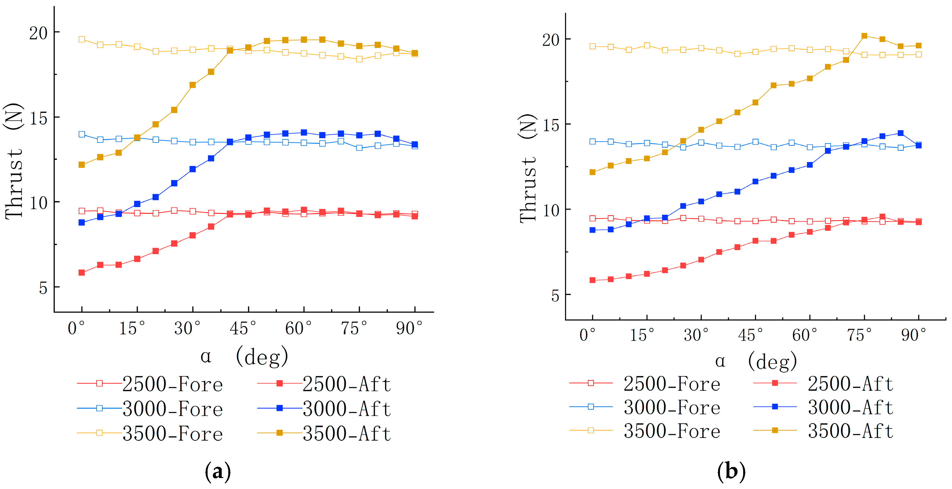
Figure 5 illustrates the variation in thrust with respect to rotor tilt angle for the fore and aft tandem rotors at rotor speeds of 2500 RPM, 3000 RPM, and 3500 RPM. In
Figure 5a, across the entire range of tilt angles for the fore rotor, the thrust remains largely unchanged, while the thrust of the aft rotor experiences significant losses at small tilt angles. This is due to the fore rotor’s wake, at smaller tilt angles, directly impacting the aft rotor’s blade plane. The aft rotor then ingests this wake as its incoming flow, resulting in a substantial increase in induced velocity, which in turn reduces the effective angle of attack of the aft rotor blades [
26].
The thrust variation of the aft rotor caused by tilt in
Figure 5b follows a similar trend to what is observed under the forward tilt condition. However, under aft tilt, the thrust of the aft rotor is more significantly affected by aerodynamic interference, and it does not recover to the same level as the fore rotor’s thrust until the tilt angle reaches 75°. In contrast, for forward tilt, the thrust of the aft rotor recovers to match that of the fore rotor at a tilt angle of 40°. This difference is primarily due to the fact that during aft tilt, the aft rotor’s wake remains within the fore rotor’s wake, leading to complex rotor wake interference. Moreover, because of the experimental setup’s constraints, the tilt nacelle length is smaller than the rotor radius, causing the aft rotor’s blade plane to be impacted by the fore rotor’s wake at most tilt angles. The aft rotor then ingests this disturbed flow, increasing the induced velocity at the blade plane. Conversely, under forward tilt, after reaching a tilt angle of 45°, the aft rotor is essentially unaffected by the fore rotor’s wake.
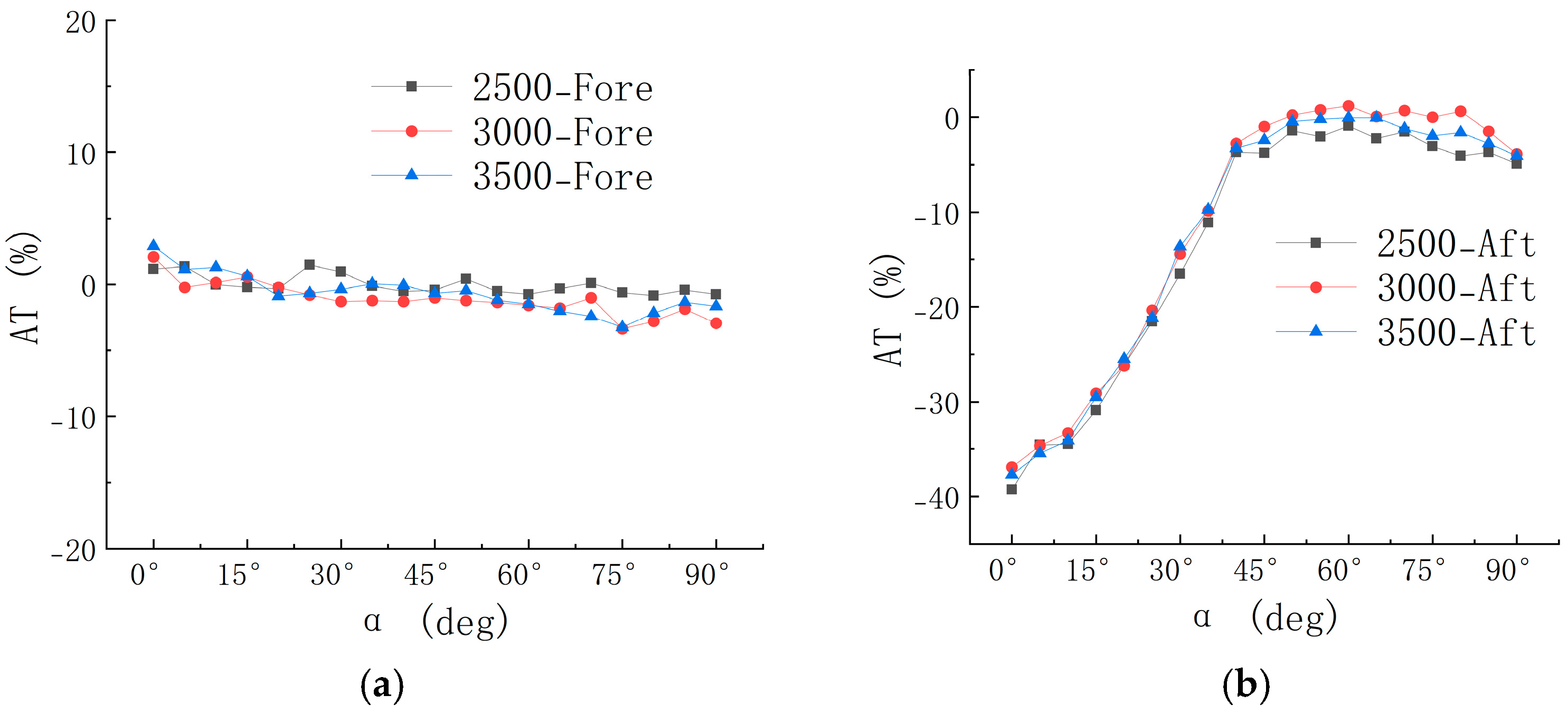
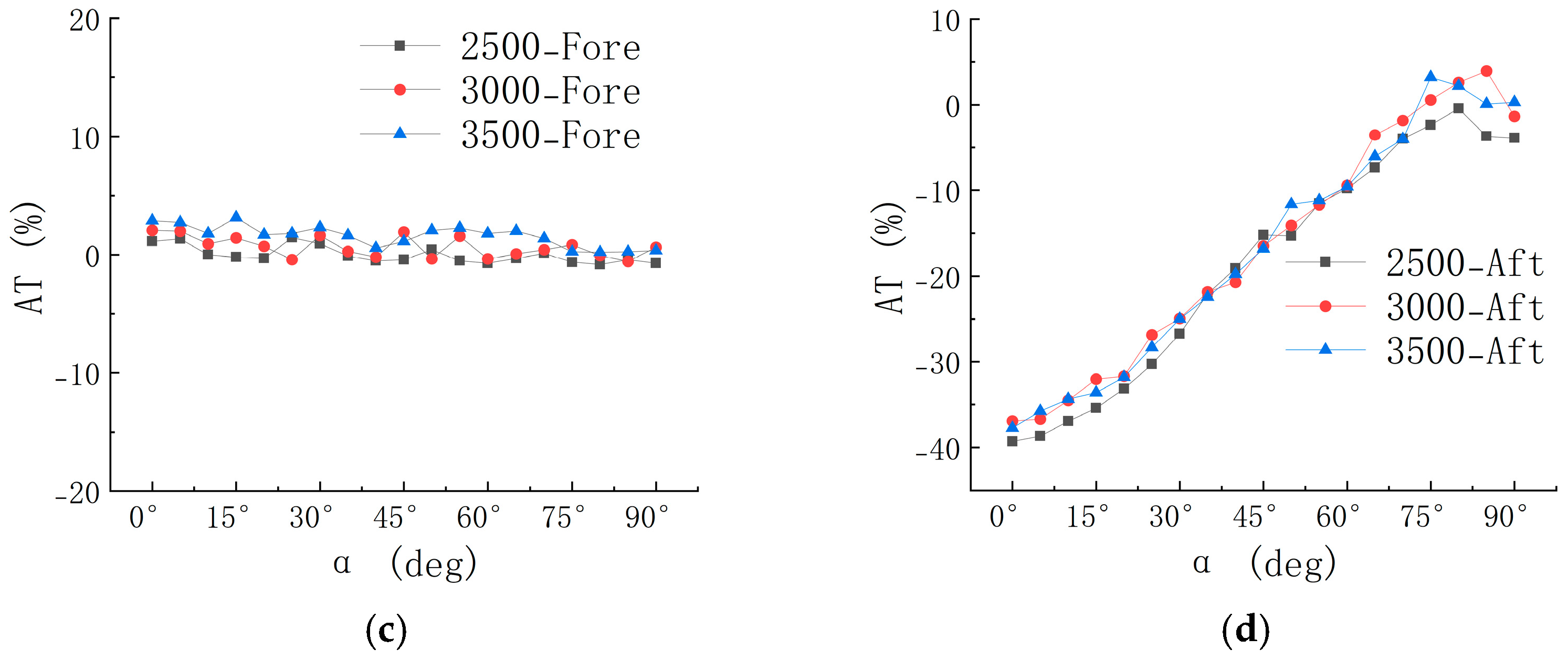
As shown in
Figure 6a,c, the thrust of the fore rotor remains largely unaffected by the tilt angle, with no significant losses observed. This is attributed to the absence of additional flow disturbances in the test environment other than the rotor-induced airflow, as well as the relatively large spacing between the fore and aft rotors, which minimizes the impact of tilt angle on the fore rotor. These findings are consistent with the experimental results reported by Zanotti [
21].
Figure 6b indicates that the aft rotor experiences the greatest thrust loss at α = 0°, with a reduction of 39.3% compared to the isolated rotor case. This loss is closely related to the degree of overlap between the thrust-generating planes of the fore and aft rotors [
17]; greater overlap leads to more severe wake interference. As the tilt angle increases, the wake interference between the fore and aft rotors weakens, allowing the thrust to gradually recover and remain relatively stable beyond α = 45°. From
Figure 6d, it can be observed that, unlike the forward tilt condition, the aft tilt condition results in more pronounced wake interference on the aft rotor from the fore rotor. As the tilt angle increases, the slope of the thrust variation rate curve during aft tilt is smaller than that observed during forward tilt, confirming that the aerodynamic interference from the fore rotor more strongly suppresses thrust recovery in the aft rotor during the tilt process. The aft rotor thrust does not begin to recover until the tilt angle reaches approximately 75°.
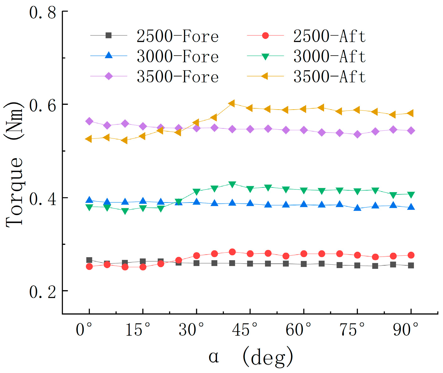
Figure 7 and
Figure 8 illustrate the variation of rotor power and torque with tilt angle under the forward tilt test condition. According to Equation (4), rotor power and torque exhibit a linear relationship and reflect the same aerodynamic performance characteristics. Therefore, to avoid confusion in the subsequent analysis, this study focuses solely on rotor power in the discussions that follow.
Here, P represents the rotor power, M is the rotor torque, and Ω is the rotor angular velocity. As shown in
Figure 7, the power of the fore rotor remains nearly constant across the entire tilt angle range at various rotational speeds. In contrast, the aft rotor power increases with the fore rotor’s tilt angle and gradually stabilizes, exhibiting this trend consistently across different rotational speeds.
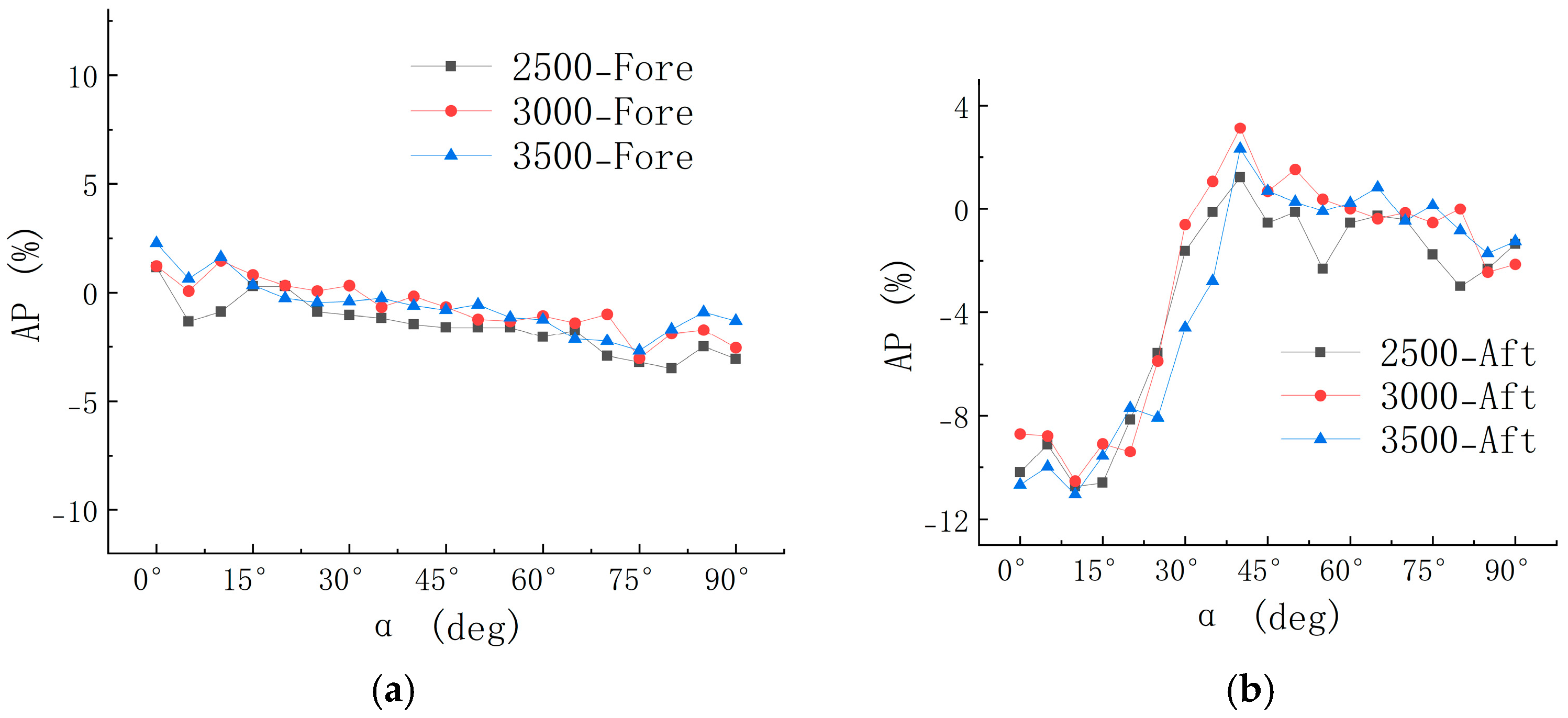
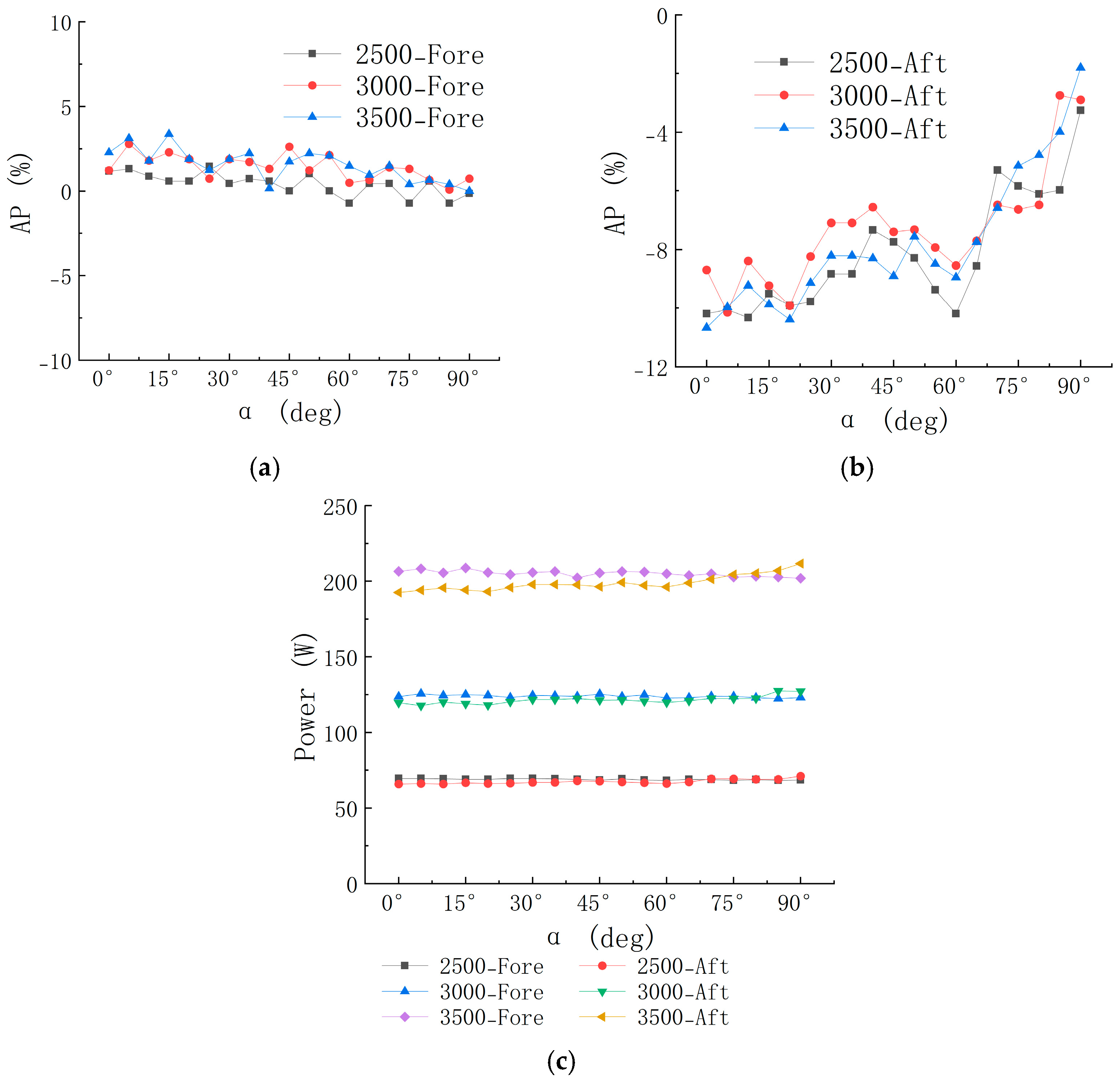
Figure 9a shows the variation in the power change rate of the fore rotor with tilt angle. The overall data remain within ±3% compared to the isolated rotor case, further confirming that under forward tilt conditions, the fore rotor is essentially unaffected by aerodynamic interference from the aft rotor. A slight increase in fore rotor power at small tilt angles is observed, likely due to a higher degree of overlap between the thrust-generating planes of the rotors. In this configuration, the aft rotor more noticeably ingests the wake from the fore rotor, increasing the fore rotor’s induced power.
In contrast, the aft rotor experiences more significant power variation under forward tilt conditions, indicating a stronger aerodynamic interference effect from the fore rotor. As shown in
Figure 9b, the aft rotor power initially decreases slightly with increasing tilt angle and then begins to rise and stabilize. This trend may be attributed to increased thrust asymmetry across the aft rotor’s blade plane at higher tilt angles. Greater power is required to counteract the resulting rotor instability, leading to a substantial increase in power consumption. Notably, when α < 40°, larger tilt angles result in more severe thrust asymmetry. At 3000 RPM and α = 40°, the aft rotor power reaches its peak, exceeding that of the isolated rotor by 3.12%. When α > 40°, the rate of change in aft rotor power gradually decreases with increasing tilt angle, and the power consumption progressively approaches that of the no-interference condition.
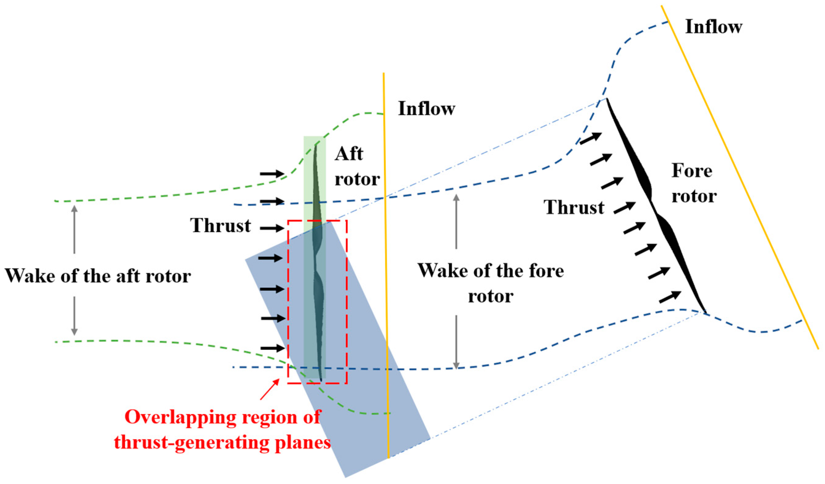
The overlapping region of the thrust-generating planes of the fore and aft rotors, as well as the predicted wake development, are illustrated in
Figure 10. The intersecting area between the green and blue shaded regions represents the overlap of the thrust-generating rotor disks. As the tilt angle increases, this overlapping area decreases, thereby reducing the degree of aerodynamic interference between the fore and aft rotors.
Figure 11 illustrates the power variation under aft tilt conditions. As shown in
Figure 11a, the power change rate of the fore rotor with increasing tilt angle is similar to that observed under forward tilt conditions, with no significant change compared to the isolated rotor case. This is expected because the fore rotor is minimally affected by rotor-to-rotor interference in this test configuration, which can be neglected. However, the aft rotor power variation rate shown in
Figure 11b differs significantly from the forward tilt condition. During aft tilt, the power variation rate of the aft rotor remains consistently negative. Although it begins to increase after the tilt angle reaches 60°, it still only reaches −1.8% at 90° under a rotor speed of 3500 RPM. This is because, during aft tilt, the wake from the fore rotor continuously affects the wake of the aft rotor as the tilt angle increases. This causes an increase in radial velocity and a decrease in axial induced velocity. According to blade element theory, this reduces the local effective angle of attack of the aft rotor blades, leading to a smaller power consumption under aft tilt than under forward tilt.
Figure 11c shows that at various rotational speeds, the power of the aft rotor is generally lower than that of the fore rotor, which differs slightly from the measurements under forward tilt. This further confirms that rotor-to-rotor interference is more pronounced under aft tilt conditions.
3.3. Effect of Rotor Speed
Rotor speed is a critical parameter for achieving attitude and position control in the tilt-rotor UAV. Depending on the specific flight mission, an appropriate rotor speed must be selected to optimize flight performance and aerodynamic efficiency.
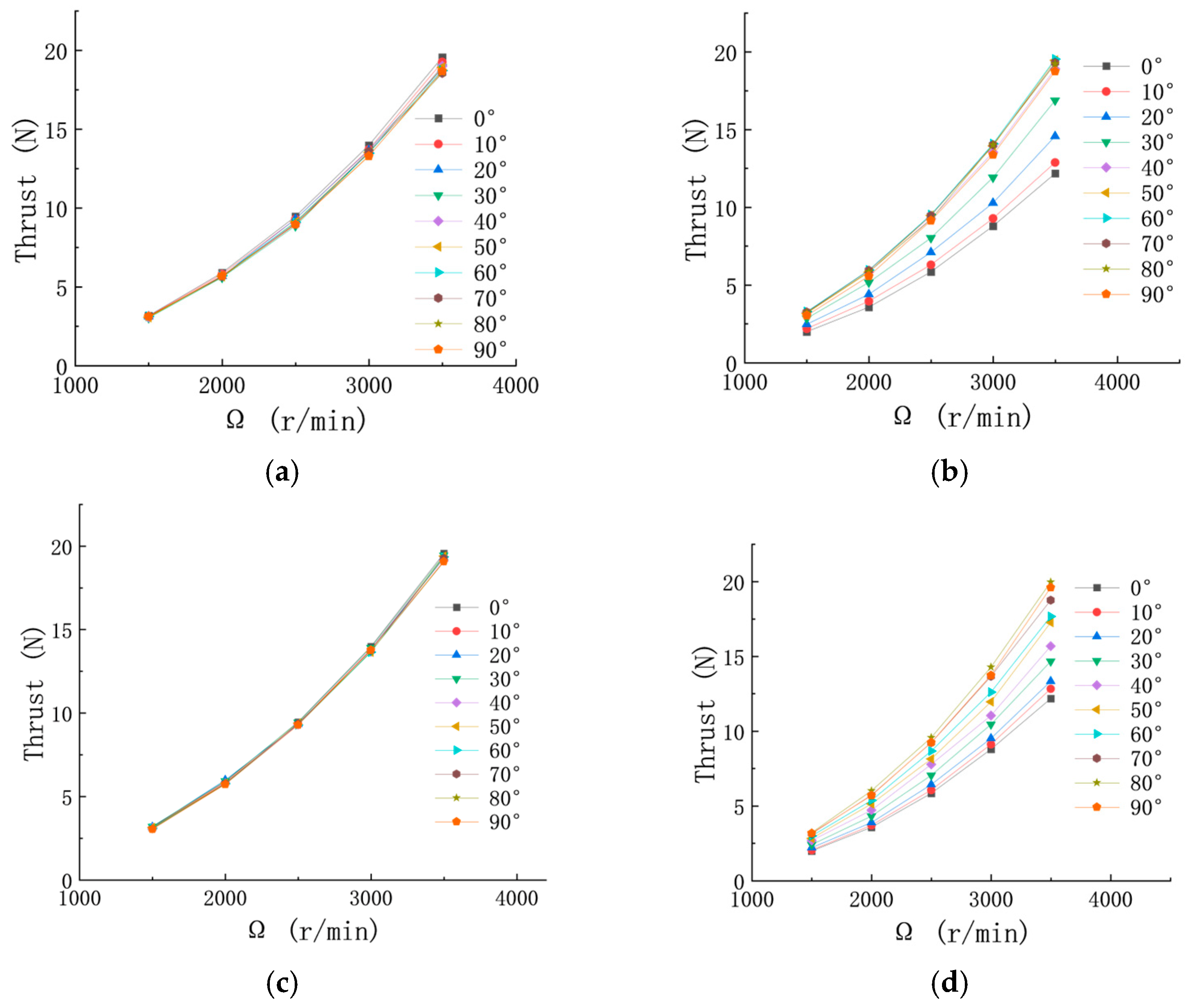
Figure 12 presents the variation in thrust for the fore and aft rotors at different tilt angles as rotor speed increases during forward and aft tilt. It can be observed that at all tilt angles, rotor thrust increases with increasing rotor speed. This trend is consistent with the principles of momentum theory: as rotor speed increases, the suction effect on the inflow becomes stronger, resulting in a higher induced velocity and consequently greater rotor thrust.
Figure 12a and
Figure 12c show the variation of fore rotor thrust with rotor speed at different tilt angles during forward and aft tilt, respectively. The thrust trends of the fore rotor remain consistent across all speeds, which aligns with the earlier analysis. However, in
Figure 12b,d, the aft rotor generates noticeably different thrust values at various tilt angles for the same rotor speed, and this difference becomes more pronounced as rotor speed increases. This phenomenon is attributed to the relatively low-Reynolds-number conditions in the present experiments. For small-scale rotors operating under low Reynolds numbers, viscous effects dominate, leading to flow separation on the blade surface and reduced aerodynamic efficiency. As rotor speed increases, viscous effects diminish while inertial effects become more significant, thereby improving the rotor’s aerodynamic performance [
22].
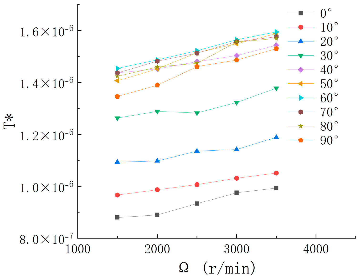
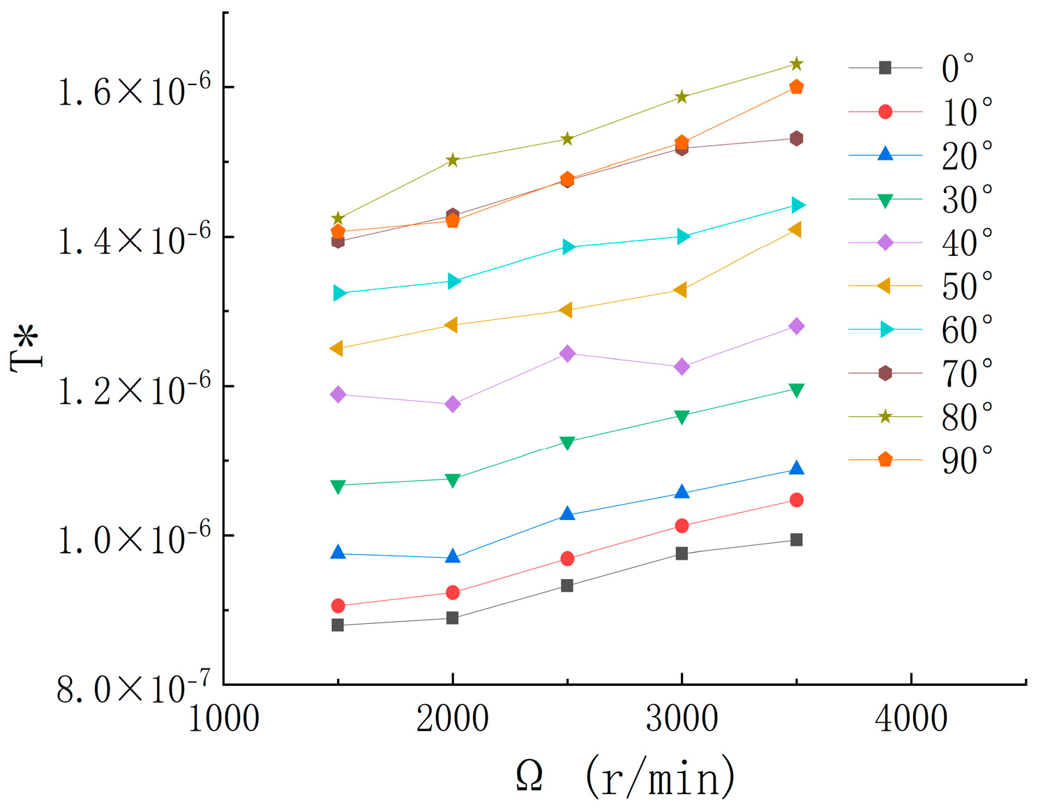
To further investigate the influence of rotor speed on interference-induced thrust, the aft rotor thrust under both forward and aft tilt conditions is normalized by the square of the rotor speed. The results are as follows:
Figure 13 and
Figure 14 show the variation of the normalized thrust of the aft rotor with rotor speed. As the speed increases, the normalized thrust T* gradually increases; however, the difference between different tilt angles remains nearly constant across the speed range. This further confirms that rotor speed has a limited effect on aerodynamic interference between rotors under the given conditions.
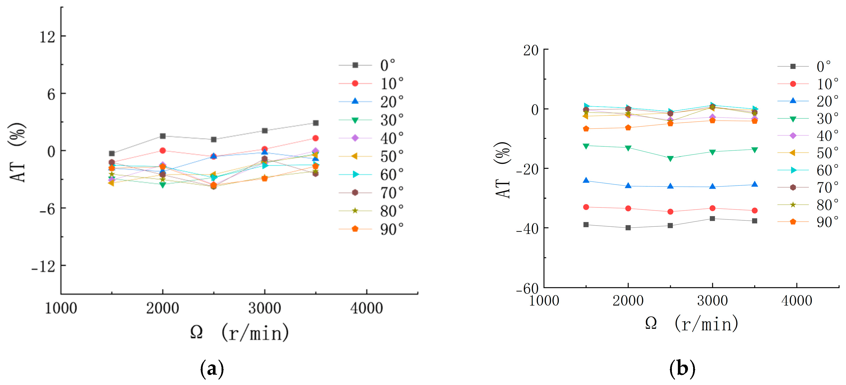
As shown in
Figure 15a,b, under forward tilt conditions, the thrust variation rates of both the fore and aft rotors remain largely consistent across the entire tested rotor speed range at each specific tilt angle. For example, the aft rotor’s thrust variation rate at α = 90° remains between −36.9% and −40% throughout the full range of rotor speeds. This indicates that rotor speed has a relatively minor effect on the aerodynamic interference between the fore and aft rotors under forward tilt conditions. The primary reason is that aerodynamic interference between rotors is mainly governed by vortex interactions [
20,
27,
28]. While increased rotor speed can alter vortex strength, the propagation characteristics of these vortices are primarily determined by the relative positioning of the rotors, which remains constant under fixed test configurations.
In contrast,
Figure 15c shows a slightly different trend under aft tilt conditions. At low rotor speeds (e.g., 1500 RPM), there is a notable thrust loss, which then recovers to levels comparable to those of the non-interfered rotor as speed increases, eventually stabilizing. This behavior is attributed to the low Reynolds number at low speeds, where viscous effects dominate. As rotor speed increases, the influence of viscosity diminishes, and the performance recovers.
Figure 15d presents the aft rotor thrust variation under aft tilt conditions, showing a trend similar to that observed in the forward tilt case. This further confirms that rotor speed has only a limited impact on rotor-to-rotor aerodynamic interference under these testing conditions.
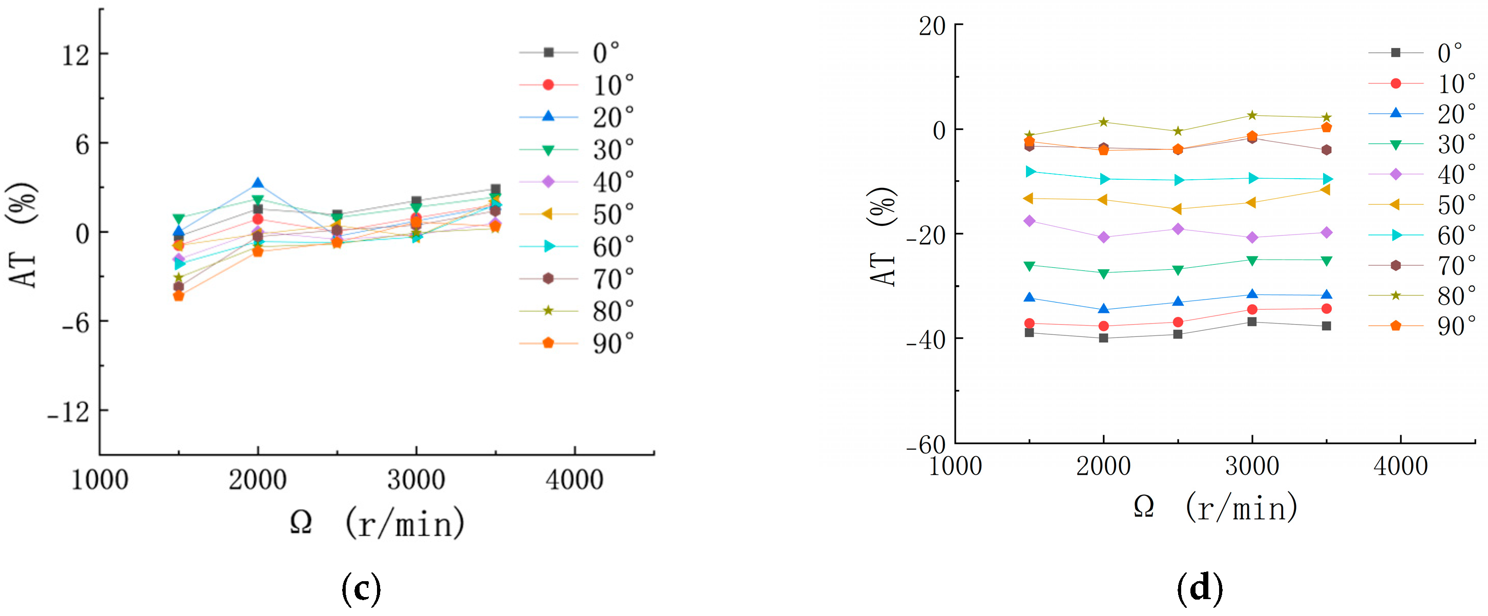
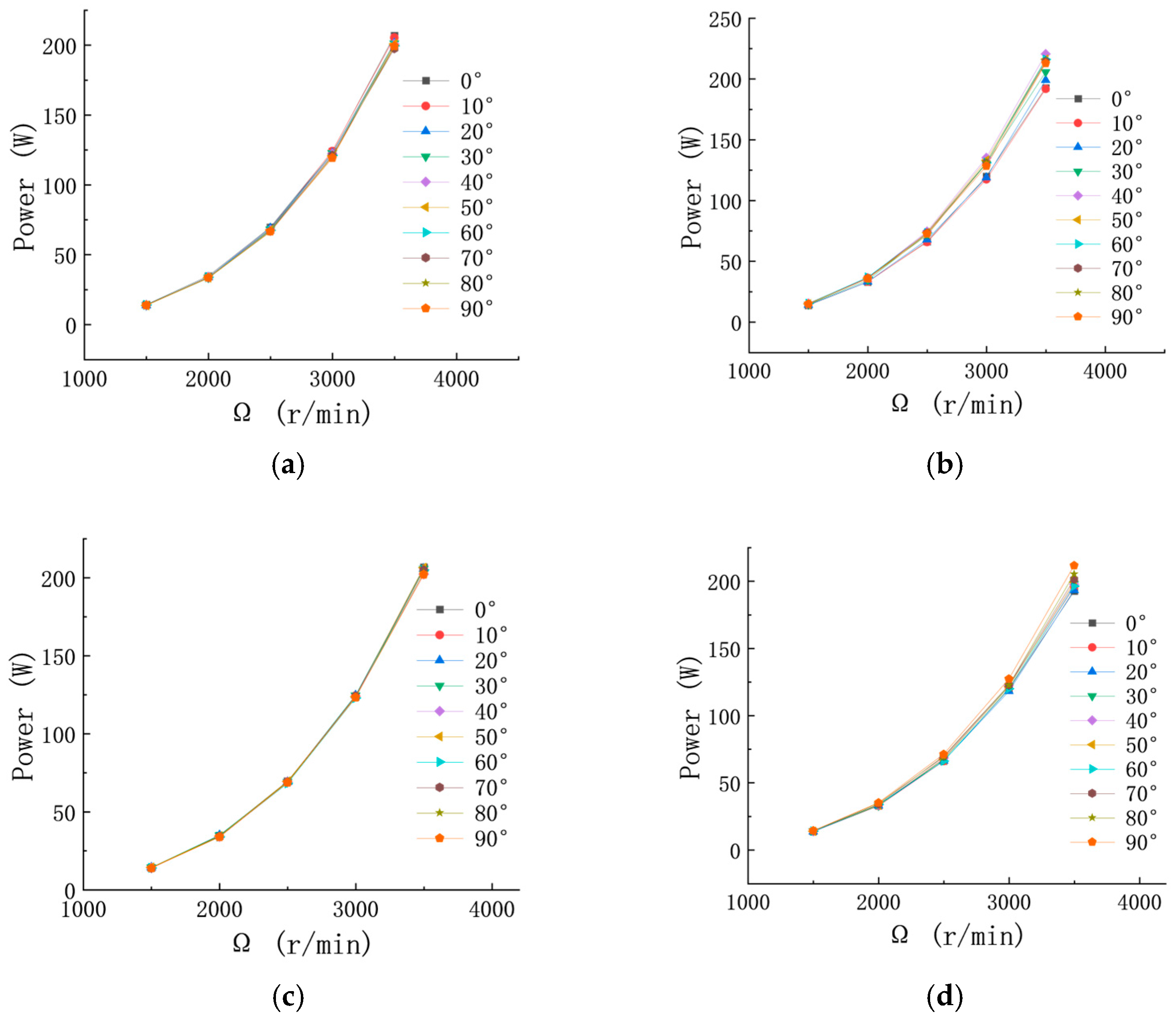
Figure 16 shows the variation of power with rotor speed for the fore and aft rotors at different tilt angles. Under various forward tilt conditions, the power of both rotors exhibits a consistent trend with increasing rotor speed—namely, power increases as speed increases. According to momentum theory, this is primarily because increasing rotor speed not only enhances the thrust generated by the blades but also increases the induced drag. As a result, greater power is required to maintain lift and overcome the increased drag, leading to a rise in power demand with rotor speed.
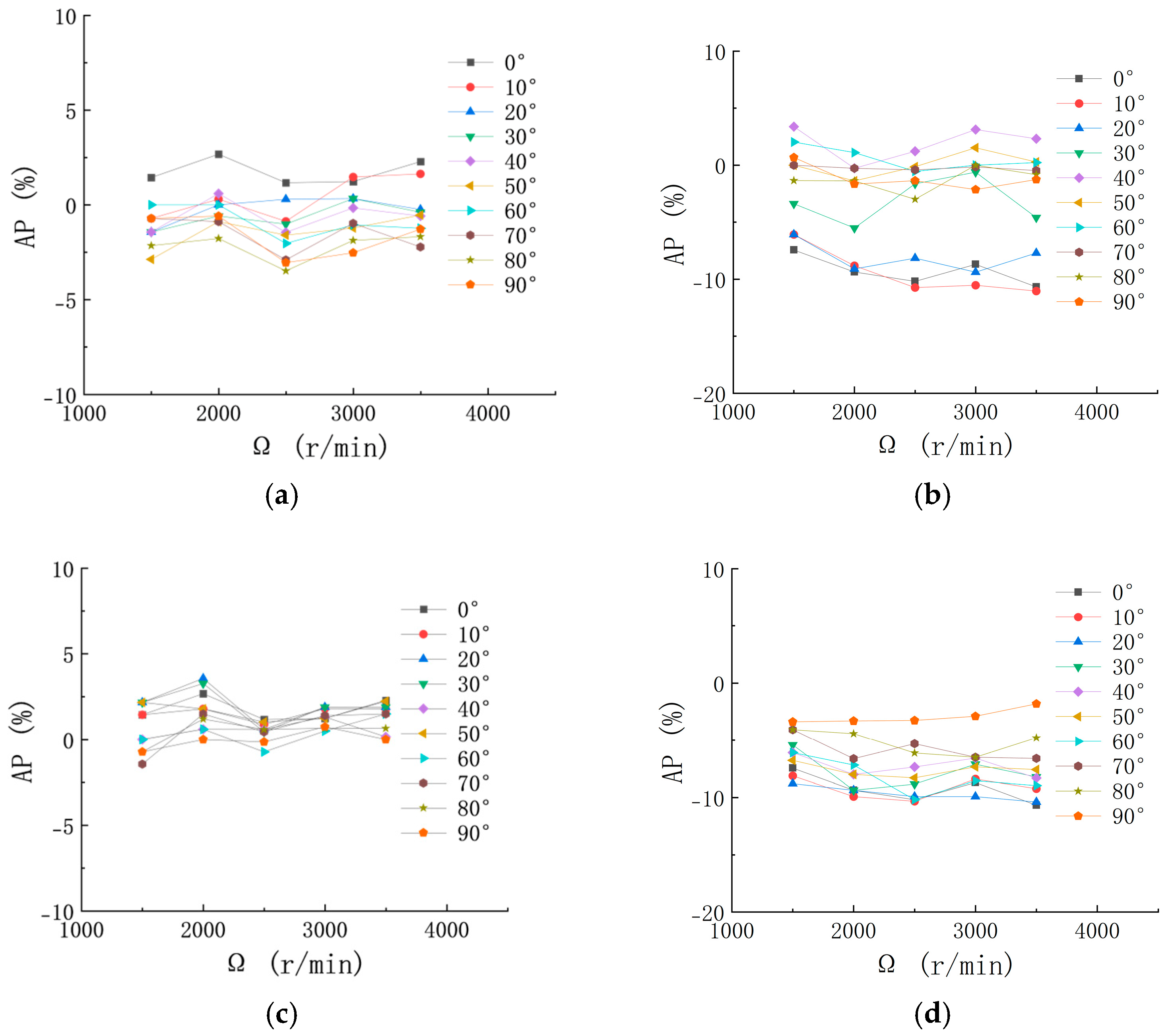
As shown in
Figure 17, the variation in rotor power change rate for both the fore and aft rotors across different conditions remains within a 3–5% range as rotor speed changes. This is consistent with the results observed in the thrust variation rate, further confirming that rotor speed has a relatively minor effect on the rotor-to-rotor aerodynamic interference under the test conditions of this study.
4. Discussion
As a promising solution to the challenges of UAM, the distributed electric tilt-rotor UAV requires a thorough understanding of the complex aerodynamic interactions between rotors and the effects of different tilt configurations. Therefore, it is of great significance to further examine the performance of the tandem counter-rotating, asynchronously tilting dual-rotor system under varying parameters.
The previous analysis demonstrated that the fore rotor is minimally affected by aerodynamic interference in both tilt configurations. Its performance parameters, including thrust and power, remain stable throughout the entire range of tilt angles. In contrast, the aft rotor is subject to more severe aerodynamic interference across all tested tilt angles. As a result, the discussion in this section focuses exclusively on the aft rotor. Comparative analysis between forward and aft tilt configurations reveals that, across all tested rotational speeds, the performance of the aft rotor changes consistently with increasing tilt angle. However, for any given tilt angle, the aerodynamic performance of the aft rotor varies significantly with rotor speed. As the tilt angle increases, the performance degradation of the aft rotor gradually recovers and stabilizes. This indicates that, under the tested conditions, tilt angle exerts a more dominant influence on rotor-to-rotor aerodynamic interference than rotor speed, making it the primary factor contributing to performance losses.
Moreover, aerodynamic interference is found to be more pronounced under aft tilt. Although aft tilt generally results in lower power consumption for the tandem rotor system, it also leads to reduced thrust generation by the aft rotor—an undesirable trade-off. Overall, the aerodynamic performance of the rotor system is superior under forward tilt conditions. When the tilt angle reaches 45°, the aft rotor’s thrust nearly recovers to the level of an isolated rotor at the same speed, whereas aft tilt requires a tilt angle of 75° to achieve a similar level of recovery. Additionally, the maximum power in the forward tilt case exceeds that of the aft tilt configuration by only 5.1%, which is a relatively small margin.
These findings indirectly confirm that when accounting for aerodynamic interactions between rotors, a configuration where the fore rotor is tilted to primarily generate lift while the aft rotor provides forward thrust exhibits superior aerodynamic performance compared to the reverse arrangement (fore rotor providing forward thrust and aft rotor tilted for primary lift contribution).


