Article

The Dual Impact of Winglets and Serrations on UAV Aerodynamic and Acoustic Performance

by
Adam Khalaf
and
John Kennedy
*,†
School of Engineering, Trinity College Dublin, The University of Dublin, D02 PN40 Dublin, Ireland
*
Author to whom correspondence should be addressed.
These authors contributed equally to this work.
Drones 2025, 9(4), 302; https://doi.org/10.3390/drones9040302
Submission received: 6 March 2025 / Revised: 9 April 2025 / Accepted: 10 April 2025 / Published: 11 April 2025

Abstract

The rising use of UAVs in various applications has underscored the critical challenge of noise pollution and aerodynamic efficiency. This study explores the dual integration of winglets and serrations on UAV propellers to address these challenges simultaneously. Through a purpose-built test rig and additive manufacturing techniques, the effects of various flaplet modifications—such as serration span, width, and spacing ratio—on the propeller’s aerodynamic and aeroacoustic performance were evaluated. Results demonstrate simultaneous improvements to thrust and both tonal and broadband noise reduction in a frequency range covering 14 shaft orders. The greatest enhancements for each feature are dependent on the blade geometry. Improvements of up to 9.7% increase in thrust, a 2.7 dB decrease in low-frequency broadband noise, and a 9.1 dB decrease in certain tonal BPF components were achieved compared to the baseline design. This research demonstrates a low-cost empirical approach to UAV propeller design, offering insights into the parametric influences of serrations and winglets. It establishes a framework for the low-cost empirical advancement of UAV propeller technologies, illustrating the substantial gains in operational efficiency and environmental sustainability achievable through iterative design enhancements.

1. Introduction

As unmanned aerial vehicle (UAV) technology leaps forward, becoming more accessible, affordable, and adept [1], society is on the cusp of a new era where the skies become increasingly populated with drones, with applications of deliveries, infrastructure inspection, and farming, among many others. However, this increasing use of drones has also brought about challenges, particularly in terms of noise pollution and aerodynamic efficiency. This requires the exploration of novel technologies and design optimisations to mitigate these issues. A systematic review by Schäffer et al. [2] reveals that drone noise is significantly more annoying than road traffic or aircraft noise, attributed to its unique acoustic characteristics such as pure tones and high-frequency broadband noise. In addition, Ivošević et al. [3] conducted subjective assessments of UAV noise perception. This showed that even low-frequency noise present in the spectrum of drones can be distinguished by listeners and often lead to negative experiences. The routing and operation of UAVs within cities will likely be constrained by noise considerations in the future [4].
The integration of winglets on UAV propellers stands out as a promising approach to addressing this dual challenge. Hariyadi et al. [5] reveal that wingtip fences—a type of winglet—on a fixed wing can significantly reduce vorticity behind the wing, thus diminishing the potential for noise while enhancing lift. Furthermore, Arshad et al. [6] conducted a CFD analysis on blended, wingtip fence, and raked winglet types on fixed wing slow-speed small UAVs. This investigation found that blended winglets introduced an 11% increase in aerodynamic quality compared to baseline wings without winglets, demonstrating their effectiveness in improving both aerodynamics and noise profiles. Optimisation studies have further refined the effectiveness of these technologies. Gölcük and Kurtuluş [7] explored the impact of elliptical winglet designs on fixed wing low-altitude solar-powered UAVs, resulting in an 8.32% enhancement in the lift-to-drag ratio compared to the baseline wing. Further, Afshari and Karimian [8] redesigned the tip geometry of a rectangular helicopter rotor blade, advancing aerodynamic efficiency and noise reduction techniques. The introduction of anhedral and eagle winglet configurations on rotor blades demonstrate up to 21% improvement in the Figure of Merit (FoM) ratio—a measure of aerodynamic performance considering the coefficient of thrust versus the coefficient of torque—while concurrently achieving a notable decrease in noise levels by up to 4.5%.
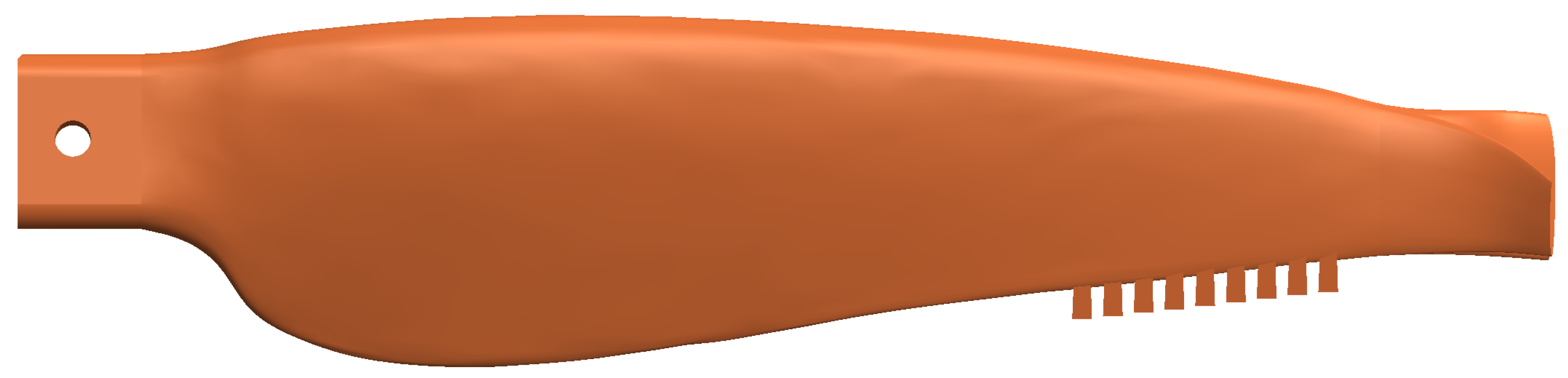
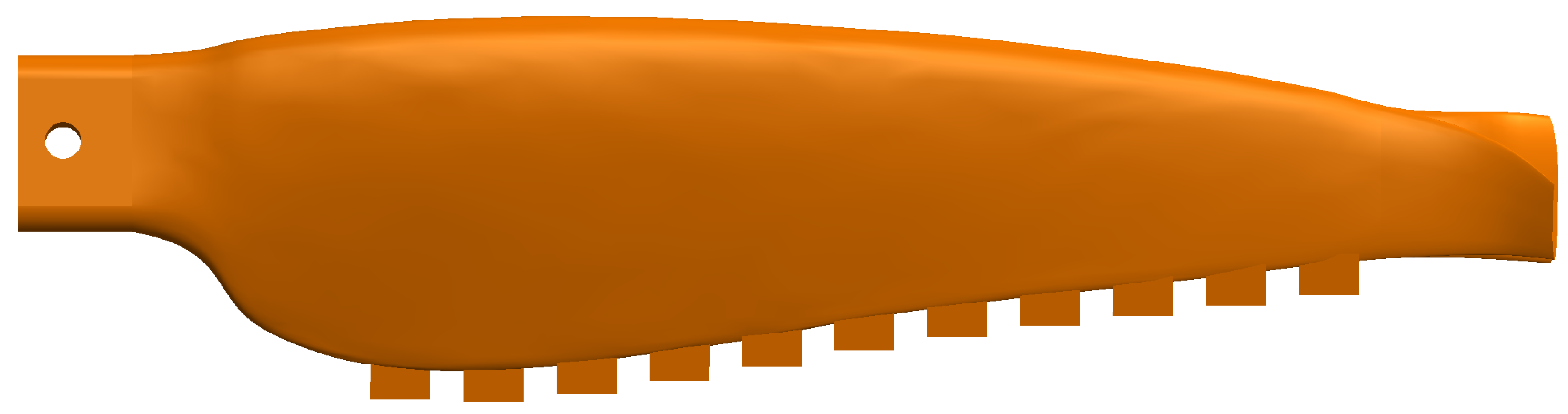
Trailing edge serrations have also been explored to reduce tonal and broadband noise associated with rotor blades without a reduction in aerodynamic performance.
A detailed review of the mechanisms of noise reduction can be found in Lee et al. [9]. The mechanisms associated with the noise reduction were investigated parametrically by Pereira et al. [10]. This work showed that trailing-edge serrations reduce broadband noise by disrupting the spanwise coherence of turbulent pressure fluctuations. Serrations therefore introduce spanwise variations in the scattering surface, causing phase differences in the scattered acoustic waves. This leads to destructive interference in the far field, effectively lowering noise levels. Additionally, the transition from the airfoil surface to the serrated edge lowers wall-pressure fluctuations towards the serration tips, reducing low-frequency noise generation. However, flow acceleration through the serration gaps can increase pressure fluctuations near the tips, limiting noise reduction at high frequencies. Under aerodynamic loading, serrations can induce counter-rotating vortices along their edges, which amplifies wall-pressure fluctuations and can increase noise levels.
Cao et al. [11] showcased that serrations can achieve a noise reduction of about 2 dB at low-to-moderate frequency ranges for small angles of attack, alongside suppressing fluctuation of aerodynamic forces. Further, Chen et al. [
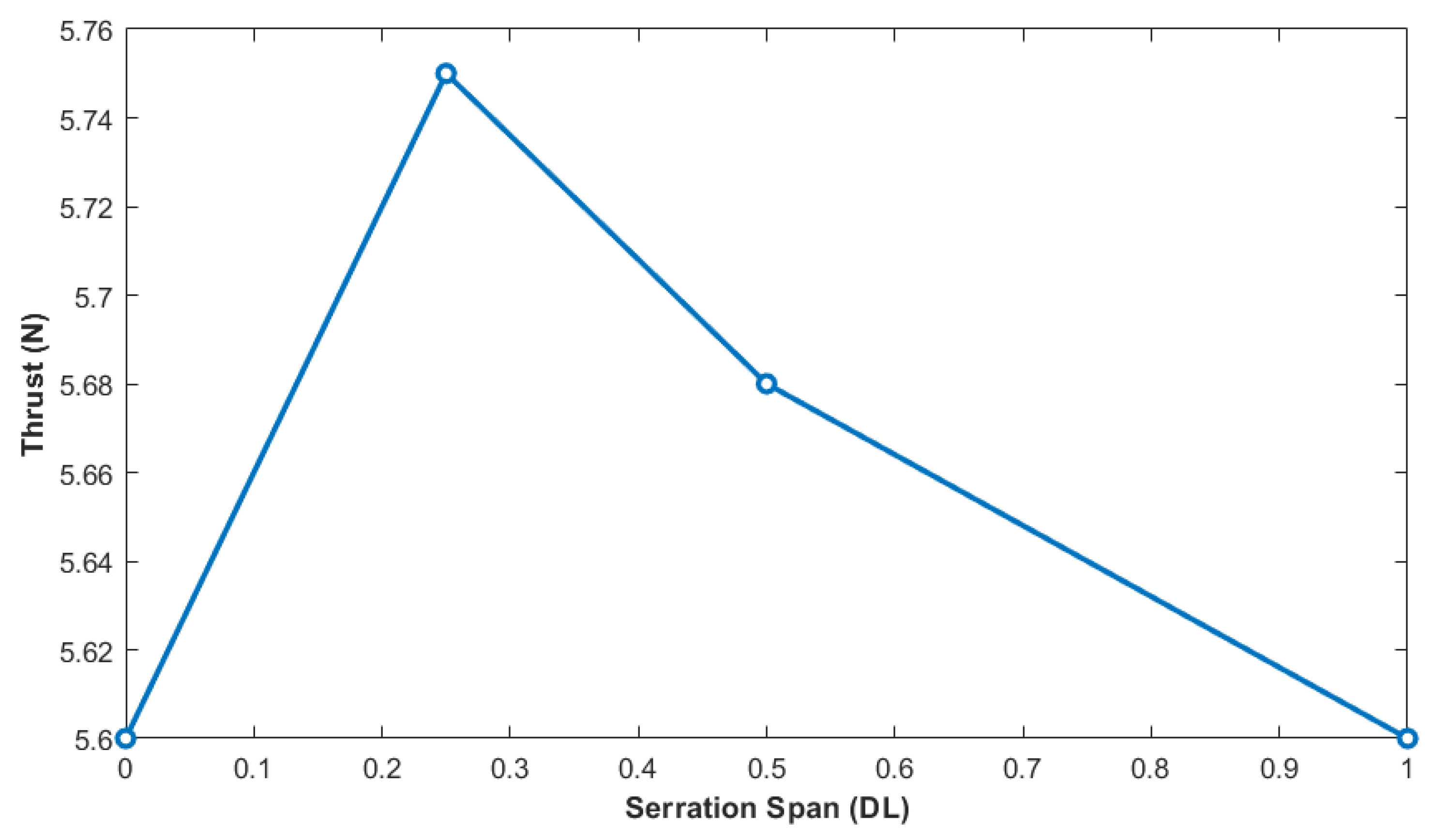
12] computationally investigated the effect of half span serrations. The half-tip wide-serrated blade was effective in reducing broadband noise by up to 3.3 dBA without detrimentally affecting aerodynamic performance. The effect of serration span was investigated by Yuliang et al. [13]. This experimental study showcased that the three-quarter serrated span propeller had up to a 3.0 dB noise reduction with an overall 6.7% higher thrust force than the baseline propeller. Yang et al. [14] explored noise reduction in multi-copter rotors by modifying the baseline rotor into a wavy design, which reduced overall sound pressure level by up to 2 dB without compromising thrust and power loading, demonstrating a practical approach to alleviate rotor noise through structural design changes. Yu et al. [15] implemented an integrated aerodynamic and aeroacoustic design method for propeller optimisation, successfully reducing the maximum total sound pressure level by 5 dB without affecting aerodynamic performance. This study showcases the potential of comprehensive optimisation in propeller design. Sun et al. [16] studied the effects of blade twist on multirotor propellers, finding a 9.3% increase in the figure of merit and a 4.3 dB noise reduction. This research highlights the significance of the blade twist in improving both aerodynamic and acoustic performance.
Recent advancements in additive manufacturing (AM) have opened new frontiers in the design and production of UAV rotor blades, showcasing significant improvements in aerodynamics, weight reduction, and manufacturing efficiency. Kovacevic et al. [17] optimised composite rotor blades for small UAVs using a genetic algorithm. The optimised blades demonstrated a deviation within 15% for thrust and torque measurements when compared to baseline models. This result validates the efficacy of AM in tailoring UAV components for specific aerodynamic requirements. Further, Balasubramanian et al. [18] emphasised AM’s operational advantages of reiterating designs, rapid prototyping, and testing through the results of weight reductions and flight time extensions, by 18% and 33%, respectively. These benefits were achieved without the extensive time and material costs associated with traditional manufacturing methods.
The necessity of blade noise reduction without a compromise of thrust is apparent. The literature provides a robust baseline of the two main noise reduction and thrust improvement methodologies, and its potential for achievement through additive manufacturing techniques. However, this work’s aims to contribute to the literature lacks in three main areas:
  • Performance Characteristics of AM Blades:
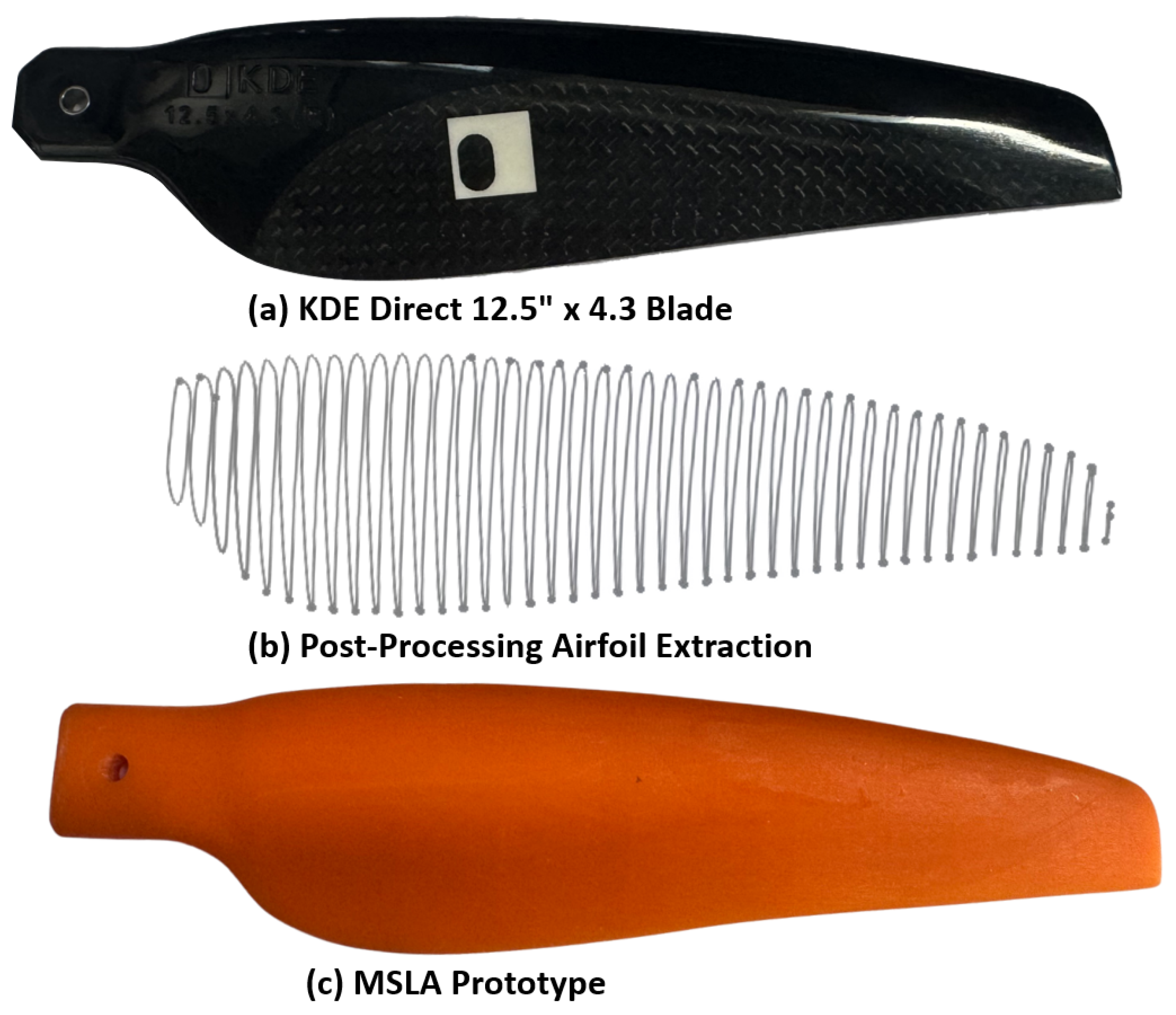
    Rotor blades are commercially made of carbon fibre—a material that is both costly and requires specialised handling. This presents opportunities for innovation in prototype manufacturing. This study investigates the feasibility of utilising cost-effective additive manufacturing techniques for the prompt prototyping of modified blades. It aims to evaluate their performance by examining thrust capabilities as well as broadband and tonal noise characteristics and comparing these results with those of the commercial counterpart.
  • Superposition of Winglets and Serrations:
    While the literature provides separate, in-depth analyses for winglets and serrations, which are both promising avenues for noise reduction and aerodynamic improvement, to date there is no research combining these two inventions.
  • Parametric Analysis of Serrations:
    The literature is extensive on the integration of protruding serrations on baseline blades. Some of the literature has even explored the effects of serration span. However, serrations are dependent on numerous factors, such as serration width and the ratio of serration spacing, which are yet to be explored sufficiently.
The combination of these contributions leads to a framework for early stage blade design which avoids the needs for high cost CFD, optimisation, and manufacturing steps. The output of the framework demonstrated here could lead directly to the production of modified blades or as a start point for more detailed design and optimisation steps. It should be noted that, unlike other aerospace applications, UAVs are often designed and operated by small-scale enterprises. These industries require a robust approach to blade design and modification that avoids high-cost development steps. The intention is to allow all UAV manufacturers and operators to address the noise challenge with available resources.

2. Materials and Methods

2.1. Experimental Set-Up

The RCbenchmark Series 1580 Thrust Stand was used to simulate the UAV propeller operation. The thrust stand was equipped with a load cell, measuring strain in the flapping axis, which was then translated to a thrust force (N) with an accuracy of 0.5% or ± 0.05 N [19]. A KDEXF-UAS35 electronic speed controller (ESC) and KDE2814XF-515 motor were used in conjunction for propeller rotation. The acoustic set-up consisted of four Gras 40PH-10 Free-field Array microphones placed in the far field, 3 diameters away, to measure sound characteristics [20,21]. The microphones were placed equiangular in a quadrant of a circle and elevated and aligned vertically with the axis of rotation. The x-axis extends in the direction of forward flight towards microphone M1, the y-axis is the plane of rotation and includes microphone M4, and the z-axis is normal to these planes. This experimental set-up is shown in Figure 1.
The methodology of measuring the noise emission of a rotor blade in a non-anechoic chamber, utilising a 90-degree microphone array as shown, is adapted from the principles provided by ISO 3744 [22]. ISO 3744 specifies the method for conducting sound power level measurements of noise sources using sound pressure in environments that approximate a free field over a reflecting plane, typically a hard floor. This standard is designed for use in non-anechoic environments, making it particularly useful for measurements in spaces that do not have access to the specialised sound-absorbing surfaces of an anechoic chamber [23]. Further validation comes from Keith and Krishnappa [24], who explore the reliability and accuracy of the ISO standards in hemi-anechoic conditions, reinforcing the standard’s adaptability. The multichannel acoustic measurements taken in this study were designed according to ISO 3744’s flexible methodology [25]. ISO 3744 is also legally mandated for use with UAVs in the European Union [26]. It is therefore likely that acoustic testing of UAVs in non-anechoic environments will be widely used in the industry. For this study, tests were conducted in a large, open-plan indoor laboratory above a smooth concrete floor. The environment meets the requirements of ISO 3744; this has been verified through the use of a calibrated reference sound source, an Acculab RSS-101, and reported in previous studies of UAV noise emission [26]. The use of a reference sound source is used for the absolute comparison test procedure from ISO 3744. This provides an accurate estimate of the magnitude of the environmental influences on the test results as a function of frequency. Over the frequency range of interest in this study the environmental correction factor K2 varies between −1.8 dB and +2.7 dB. The potential for destructive interference due to ground reflections was evaluated and it was found that destructive interference will occur at a frequency of 2960 Hz, which is roughly three times the highest BPF frequency considered in this work. The impact on the environment and test geometry on the measured values was deemed negligible and to further guarantee comparability, noise measurements across various blade geometries were conducted under these identical test conditions.

2.2. Blade Modification

The KDE Direct 12.5″ × 4.3, Triple-Edition Series CCW propeller served as the basis for the experimental investigation (Figure 2a). The baseline propeller was digitised via a Sol 3D Scanner, employing laser triangulation and white light techniques. In post-processing, the blade was sectioned at 4 mm intervals along the feathering axis to extract 2D airfoil contours representative of the propeller’s geometry (Figure 2b). These contours were then lofted to generate a 3D model of the baseline propeller (Figure 2c).
The parameters of the winglet design and the serration shape have previously been reported by the authors [27]. Preliminary work focused on the geometries of the winglet and serrations separately. Several winglet geometries were investigated, and the best performing was chosen for investigation in this study. Similarly, for the flaplet serrations several individual geometries were investigated and the best performing was chosen for this study. In this work, dual winglets in the form of a dihedral and eagle wingtip were superimposed on the baseline blade. This geometrical design and appropriate dimensions (in mm) are showcased in Figure 3 and Figure 4.
Flaplet serration modifications were specifically aimed at enhancing the blade’s aerodynamics and acoustic signature. This study conducted a parametric analysis to enhance the design further. This investigation focused on the independent influence of serration span (“DL”), serration width (“Width”), and the ratio of serration spacing (“RoS”). Figure 5 illustrates the baseline serration geometry, while Table 1 presents the varied parameters under consideration. Further, figures of the respective changes from in Table 1 are evident in their respective section analysis.
Blades were prototyped using an Original Prusa SL1S masked stereolithography (MSLA) printer with the Prusament Resin Tough. Models were printed at a 40° angle to remove the necessity of supports and ensure an accurate surface finish. The printing settings used and printing orientation are provided in Table 2 and Figure 6, respectively.

2.3. Experimental Testing

The propellers operated at a rotational speed of 5000 RPM. This operational speed corresponds to a tip Mach number of 0.26 and a Reynolds number of 4.2 × 10 4 , calculated using the blade’s tip chord length. Data acquisition for both aerodynamic and aeroacoustic metrics was performed concurrently over a span of two minutes. Aerodynamic measurements were sampled at a frequency of 43 samples per second, while aeroacoustic data were captured at a rate of 40,000 Hz. To ensure the reliability of the results, measurements for each blade configuration were repeated three times for three separate instances. This procedure established repeatability of the test procedure.

2.4. Data Processing

During the 2 min testing interval, data collection resulted in a total of 5160 samples for thrust and 4,800,000 samples for noise measurements. Variability in the motor’s rotational speed introduced fluctuations in aerodynamic performance. To accurately represent the performance characteristics of the sampled blade, the average values, standard deviations, and respective standard errors of key aerodynamic performance metrics were computed.
The noise data were analysed using a Fast Fourier Transform (FFT) with 32,768 points (nfft) and a resolution of 1.22 Hz. The analysed noise spectra are subsequently presented in terms of shaft order (SO), which corresponds to the harmonics associated with the propeller’s rotational speed. Of particular importance in this analysis is the blade pass frequency (BPF). The BPF is a measure defined by the frequency observed by a stationary point as blades of the propeller pass during a single rotation.
A peak detection and deletion method was utilised to distinguish between tonal and broadband noise components within the analysed spectra [28]. This technique, which applied a resolution of S O / n f f t , involved the identification and subsequent elimination of noise peaks that exceeded a threshold of 5 dB above the median noise level within a predefined surrounding range of 100 Hz. This approach facilitated the isolation of blade, motor, and other peaks from the broadband noise [29]. Similarly, it allowed for the extraction of propeller tones at the BPF for tonal noise analysis. Figure 7a showcases the noise measurements of the background, motor, and KDE Direct blade. The signal-to-noise ratio (SNR) is a critical factor in determining the intelligibility of sounds against background noise. Figure 7a showcases a minimum SNR of 10 dB, which extends to 30 dB after BPF 2. This is a sufficient difference for the signal to be distinguishable and reliable for measurements and analysis [22]. The peak detection and deletion method was initially applied on the commercial KDE Direct blade. The noise data from the processing steps are reported in Figure 7b. Both the tonal and broadband analysis was conducted over a range of 14 shaft orders which corresponds to a frequency range of up to 1200 Hz. Therefore this study is limited to considerations of low-frequency broadband noise.
Noise measurements across various blades’ geometries were conducted under identical test conditions to guarantee the comparability of the data. This uniform approach to testing across all blade designs allows for valid comparisons, despite the constraints of a non-anechoic testing environment.

3. Results and Discussion

3.1. Three-Dimensional Printing Evaluation

The nominally identical MSLA 3D-printed blade was compared with the commercial blade to validate its manufacturing process and before analysis of modifications to the geometry. The aerodynamic and aeroacoustic performance agreement is shown in Table 3, Table 4 and Table 5.
The MSLA 3D-printed prototype shows a 4.1% difference in average thrust when compared to the KDE commercial propeller, along with increases of 2.2 dB in broadband noise and up to 5.2 dB in tonal noise. These performance discrepancies are attributed to the MSLA model’s post-processing steps and the mechanical characteristics of the MSLA resin. The original KDE blade underwent a 3D scanning process using a SOL 3D Scanner, which has an accuracy limit of 0.1 mm, introducing potential inaccuracies in the model. Additionally, the physical properties of MSLA resin, notably its reduced strength and stiffness compared to carbon fibre materials, likely cause increased blade flexing during use. Such flexing can alter the blade pitch and angle of attack, leading to heightened noise from turbulence and possible resonance effects. A decrease in tonal noise was recorded at BPF 2 and at a 90° orientation, diverging from the general noise trend and suggesting a change in noise directivity due to manufacturing differences. Despite these variations from the commercial blade, the MSLA blades showed high repeatability and reproducibility. The reliability of the MSLA blades ensures that they are a suitable baseline for further design modification studies.

3.2. Winglet Serrated Blades

The dihedral-eagle winglet blade with flaplet protruding serrations was evaluated against the new baseline blade, namely the MSLA copy of the KDE Direct blade. The aerodynamic and acoustic performance is showcased in Table 6, Table 7 and Table 8.
(i)
Thrust Performance
The superposition of dihedral-eagle winglets and flaplet serrations along the entire span of the blade leads to a 3.13% increase in thrust performance compared to the MSLA baseline blade. However, incorporating these features may also introduce stability issues in the blade’s aerodynamic performance, as seen by the slight increase in thrust measurement uncertainty for the dihedral-eagle flaplet blade.
(ii)
Broadband Noise Performance
The dihedral-eagle flaplet blade consistently reduces broadband noise across the array of microphones. The most notable reductions are observed at the offset angles, 60° and 90°, whereas at the frontal angles, there is less reduction of broadband noise. This indicates that the modifications are particularly effective in mitigating broadband noise at side angles.
(iii)
Tonal Noise Performance
In the tonal noise spectra, a general reduction is observed, with a notable exception at the second blade pass frequency (BPF 2) when viewed at a 90° emission angle. This exception arises due to the MSLA baseline blade demonstrating a reduced intensity at this frequency and angle, as previously discussed. At frontal angles, the initial three BPFs exhibit only a slight decrease in blade tone levels. Notably, the most significant impact of the modifications at this angle is observed at BPF 4, indicating enhanced effectiveness of the winglet and serrations at higher frequencies from this viewpoint. In contrast, at a 60° angle, the modifications demonstrate increased noise reduction at lower frequencies, achieving a tonal noise reduction of up to 7.7 dB for the first and second BPFs. However, the effect diminishes for the third and fourth BPFs, with a marginal tonal noise reduction not exceeding 0.3 dB, indicating a lesser impact of the modifications on higher frequency noise. The modifications result in uniform noise reductions at 30° and 90°, with the extent of reduction progressively increasing across the BPF spectrum, highlighted by a 2 dB and 5 dB reduction at BPF1, respectively, and a final reduction of 7 dB at both angles at BPF 4. These results highlight the potential for low-noise technologies to modify tonal directivity, in this case due to the modified tip geometry.

3.3. Effect of Serration Span

The dihedral-eagle blade with flaplet serrations at quarter span (DL = 0.25) is shown in Figure 8. Additionally, a half span (DL = 0.5) design is investigated.
The thrust, broadband, and tonal performance metrics of the modified flaplet serrations are compared against a new baseline, namely the full span flaplet serrated dihedral-eagle winglet. The results are presented in Table 9, Table 10, and Table 11, respectively. The values reported here are additional to those reported against the original baseline blade in Table 6, Table 7 and Table 8.
(i)
Thrust Performance
Table 9 demonstrates how the serration span affects thrust generation. Serrations applied over only half the blade span (DL = 0.5) leads to a 1.5% increase in thrust. Further restriction of the serration span to the top quarter of the blade (DL = 0.25) resulted in a stronger increase in thrust by 2.7%. The increased thrust performance from partial serrations, particularly when limited to the top quarter of the blade, indicates a more localised and effective modification of the flow. Through concentrating the serrations in areas of the most effective interaction with the flow, the blades’ aerodynamic efficiency is enhanced without introducing excessive drag. The potential for serration span optimisation is highlighted by the limit designs of no serrations (DL = 0) and full serrations (DL = 1), whereby both models have an equal thrust of 5.6 N. This is visualised in Figure 9 and Table 12.
(ii)
Broadband Noise
Partial serrations on the dihedral–anhedral winglet blade achieve further reductions in broadband noise compared to a blade with full span serrations. At a 0° emission angle, both DL configurations demonstrate noise reductions, with the quarter span serrations outperforming the half span. This indicates that serrations located closer to the blade tip have a more pronounced effect on reducing noise emission in this direction, likely due to their impact on tip vortices. Moving to the side measurements, the increasing noise reduction from 30° to 90° for both serration spans is indicative of the serrations’ impact on the blade’s lateral noise emission. Particularly, the quarter span serrations showed the strongest reduction at 90°, which underscores the benefit of this span serration in disrupting sideline noise emission. The serrations likely introduce small-scale turbulence that breaks down coherent structures more efficiently when placed closer to the blade tips, which is consistent with the larger reduction in noise levels observed at this span.
(iii)
Tonal Noise
At BPF1, both the half and quarter span configurations exhibit noise reduction at 0° and 30°, with the quarter span configuration providing a greater average tonal reduction at these locations. However, analysing the entire array at the fundamental blade pass frequency, the average tonal reduction is greater for the half span compared to the quarter span. This trend is exhibited throughout the entire BPF range. Therefore, half span serrations provide more reduction at lateral angles, whereas the quarter span serrations reduce more frontal tonal peaks. Further, at lateral angles at BPF 4, reductions are not as significant or have a slight increase. This suggests a point of diminishing returns at higher frequencies, where further reductions in serration span fail to reduce noise and may instead increase it at certain frequencies. However, the modified serrations still provide an overall net tonal reduction compared to the full span serration blade.

3.4. Effect of Serration Width

The dihedral-eagle blade with triple width flaplet serrations (Width ×3) is shown in Figure 10. Additionally, a double width flaplet serrations (Width ×2) was tested.
The effect of the width of serrations are evaluated and compared against the full span flaplet serrated dihedral-eagle winglet as a baseline. The results of thrust, broadband, and tonal noise are presented in Table 13, Table 14, and Table 15, respectively.
(i)
Thrust Performance
Doubling the serration width results in a thrust increase of 6.4%, whereas tripling the width yields a slightly lower increase of 5.9%, both measurements relative to the original baseline serration width. These results suggest an increasing trend in thrust up to an optimum serration width, beyond which there are diminishing returns. The observed increase in thrust with doubled serration width suggests that the benefits of delayed flow separation and enhanced lift outweigh the potential penalties of increased drag. However, the lesser increase in thrust from tripling the serration width compared to doubling implies a non-linear relationship between serration size and thrust generation, suggesting that increased drag begins to negate the flow control benefits provided by serrations.
(ii)
Broadband Noise Performance
Table 14 shows that doubling the serration width has a negligible effect on broadband noise at most measured angles, with the exception of a noise increase at 60°. Conversely, tripling the serration width leads to a consistent reduction in noise across all angles, with improvements up to 0.5 dB observed at 0°, 30°, and 90°. Larger serrations may be more effective at breaking up the coherent structures at the boundary layer that are responsible for noise generation. However, the fact that doubling the serration width resulted in a noise increase at 60° suggests that simply increasing serration size does not uniformly reduce noise, highlighting a complex relationship between the flow dynamics affected by serration dimensions and the resultant acoustic phenomena.
(iii)
Tonal Noise Performance
Increasing the serration width to double the original size generally provides a consistent greater reduction in tonal peaks across most angles and frequencies, by up to 4.4 dB. However, further increasing the width to three times the original does not continue this trend as, in some cases, it increases the tonal peaks. The data establish a trend where both doubling and tripling the serration width minimally affect tonal noise at 60° for the first three BPFs.Furthermore, the greatest reductions across BPFs 1-3 occur at the 30° angle, while for BPF4, the most significant reduction is observed at the frontal microphone. This highlights that at higher frequencies, both serration widths shift their reduction to frontal angles.

3.5. Effect of Spacing Ratio

The dihedral-eagle blade with three times spacing-to-width ratio (RoS ×3) is shown in Figure 11. Additionally, a blade with two times spacing-to-width ratio (RoS ×2) was tested.
The effect of the spacing ratio is reported in Table 16, Table 17 and Table 18, whereby all values are also compared against the full span flaplet serrated dihedral-eagle winglet as the baseline.
(i)
Thrust Performance
Changing the spacing ratio affects thrust performance in both positive and negative ways. Doubling the spacing ratio results in a 1.6% thrust increase, while tripling it leads to a 1.4% reduction. Doubling the spacing ratio creates wider gaps, allowing improved flow interaction between serrations and a more balanced aerodynamic performance. However, tripling the spacing ratio enlarges the gaps to a point where it diminishes aerodynamic benefits, potentially due to reduced effectiveness in flow control. The larger gaps may cause the serrations to lose their effectiveness in manipulating the boundary layer and controlling the flow over the blade surface, leading to induced drag.
(ii)
Broadband Noise Performance
A greater increase in the spacing ratio consistently results in greater broadband noise, particularly noticeable at 60° where the highest noise reduction is recorded for the tripled spacing. This suggests that there might be a critical point beyond which further increasing the spacing ratio results in a proportional increase in noise. The noise reduction at 90° for the doubled spacing ratio contrasts with the general trend of noise increase. This exception might reveal a specific interaction between the flow structures caused by serrations and the blade’s wake, especially pronounced at higher frequencies and this angle.
(iii)
Tonal Noise Performance
Increasing the spacing ratio generally decreases tonal peaks, indicating a reduction in tonal noise across most angles and BPFs. Tripling the spacing ratio yields a more uniform and greater reduction in tonal noise for the first three BPFs, demonstrating improvements over doubling the spacing ratio. This suggests an interaction between serration spacing and noise generation, where a tripled ratio succeeds in noise mitigation at specific operational frequencies and angles. However, the relationship between the serration spacing ratio and noise output is complex. At lower BPFs, larger spacing generally leads to a reduction in noise at frontal measurement points (0° and 30°), but an increase at side angles (60° and 90°). The directivity and magnitude of noise reduction or increase is highly dependent on the blade passing frequency.

3.6. Overall Comparison

The serration modifications, as highlighted above, have both beneficial and detrimental effects on the baseline blades for each of the performance metrics. An overall analysis is provided in Table 19 and Figure 12.
Doubling the serration width emerges as the optimal choice for enhancing both thrust performance and tonal noise reduction. This result is reported in Figure 13 with a comparison to the baseline MSLA blade. While tripling the serration width provides thrust performance comparable to doubling, it also enhances broadband noise reduction. However, each modification targets a specific type of noise mitigation; doubling the width is less effective for broadband noise reduction, whereas tripling it is less effective at tonal noise reduction. Therefore, when the objective encompasses the reduction of both broadband and tonal noises, the DL = 0.50 modification is the preferred choice. This option is suitable for broader noise mitigation with a compromise in the thrust gained. It should be highlighted that these benefits are in addition to those provided by the baseline flaplets applied to the blades.

4. Conclusions

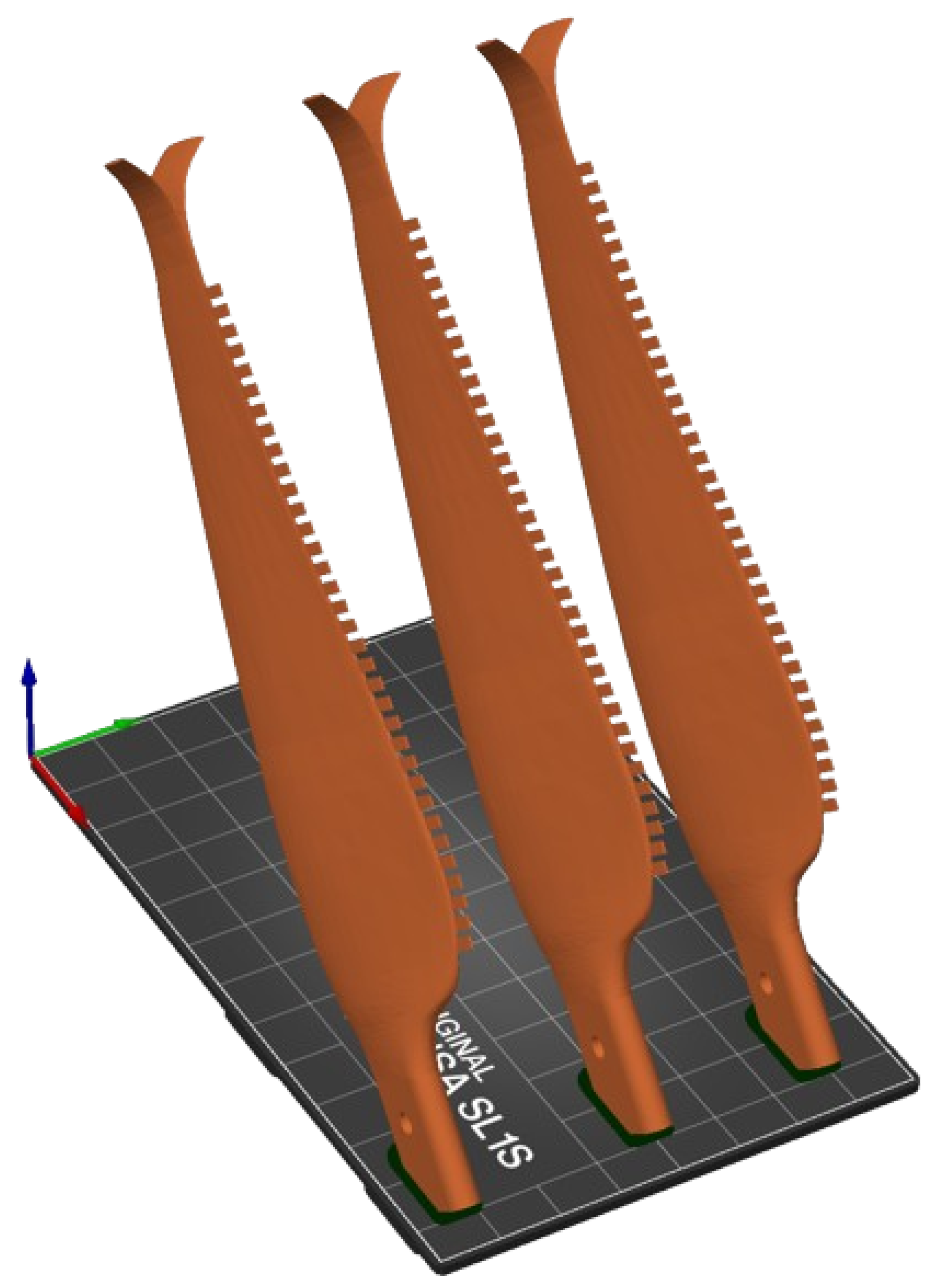
The integration of winglets and serrated edges into UAV propellers significantly enhances aerodynamic efficiency and reduces noise emissions. These findings highlight the potential for improvements in UAV operational performance and positive environmental impacts achieved through rapid low-cost prototyping. Blades manufactured using MSLA technology represent a significant advancement for the rapid production of novel concepts. This innovative approach allows for the creation of highly precise and customised blades, setting new standards for optimisation in manufacturing processes through its repeatability and reliability. By utilising MSLA technology, baselines for optimisation can be established, enhancing efficiency in the design process. This is particularly beneficial in the early stages of development, where time and cost are of paramount importance. Each set of blades used in this study were produced with a material cost of EUR 2.20 and in less than 4 h print time, enabling a very rapid and lost cost methodology for the development of advanced blade concepts. The flight worthiness of these modifications is an open question and likely a UAV operator would realise the final design iteration with a traditional manufacturing choice to increase reliability in flight. During the laboratory testing there were no failures of the MLSA blades despite extensive testing on multiple printed copies of each design which suggests the blades may be worthy of in-flight tests in controlled settings.
The designs used in this study provided up to a 10% increase in thrust. Expectations for flaplet serrations in isolation based on the work of Yuliang et al. [
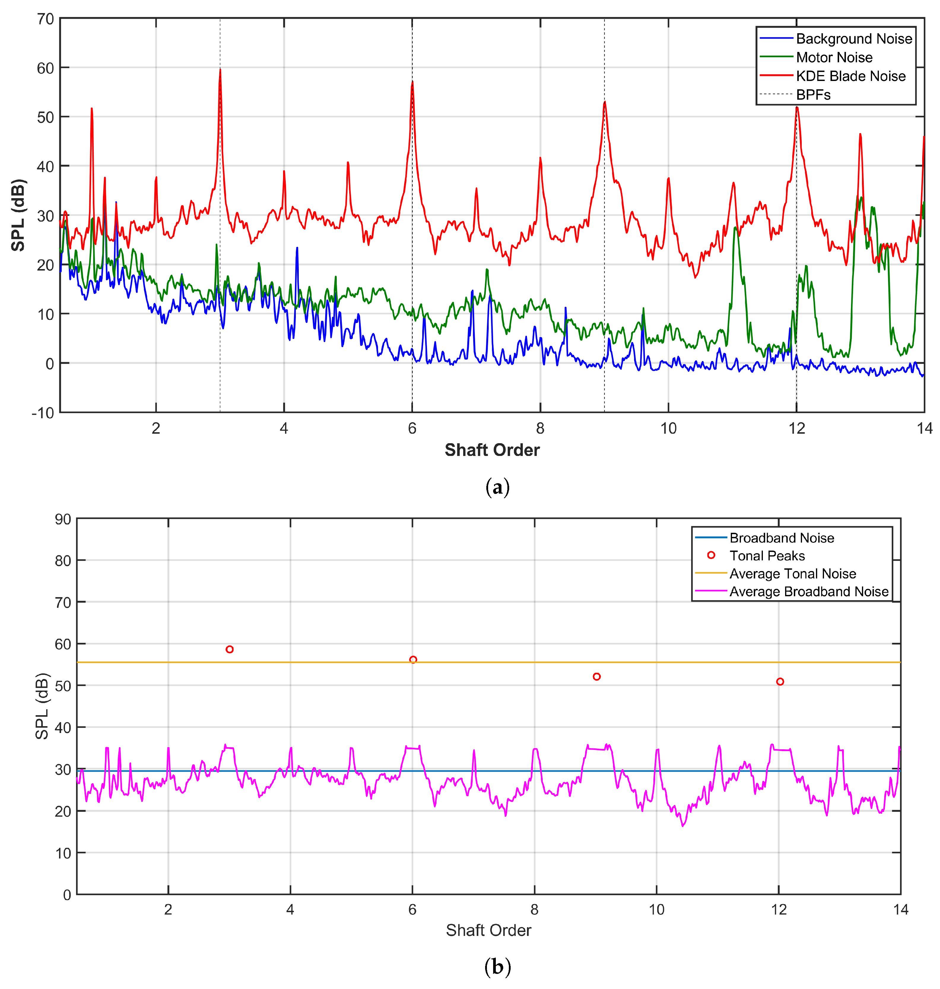
13] would also be for a 10% increase in thrust and therefore the winglets used in this study may not be providing significant improvements in the aerodynamic performance of the blades. A direct comparison with noise reductions reported in the literature is challenging since there are few works which report low-noise technologies applied in combination. The propeller designs tested here are smaller and operate at a lower Reynolds number range than several examples reported in the literature. The noise emission analysis reported in this work is limited to the range of 14 shaft orders, or approximately 1200 Hz. Considering the total noise emission in this range, both tonal and broadband, there was a range of over 5 dB between the best and worst performing designs tested. The best performing design achieved a total reduction of 14 dB in this frequency range. This is significantly higher than the 3 dB improvements reported by Yuliang et al. [13]. Therefore, the noise reduction of the winglet and serrations is likely to be additive. An optimisation of multiple low-noise technologies applied in combination using traditional techniques may be prohibitively expensive for the UAV industry. This work demonstrates that a parametric experimental investigation may provide significantly improved performance in the frequency range of interest for a UAV operator.
This study further underscores a complex balance between thrust enhancement and noise reduction, including both broadband and tonal noise over a range of 14 shaft orders. Notably, doubling the serration width provides the most significant thrust enhancement and noise reduction. Tripling the serration width yields a similar increase in thrust and reduces low-frequency broadband noise. Conversely, half span serrations succeed in reducing both types of noise, though this comes at the expense of a reduced thrust gain. These results highlight the advantages of superimposing winglets and flaplet edges, emphasising the utility of detailed parametric studies for the low-cost optimisation of UAV propeller designs. While this study establishes a foundational understanding, future research is warranted to explore the comparative performance of carbon-fibre manufactured propellers against the MSLA prototypes used in this study. High performance engineering printing materials, combined with higher fidelity scanning techniques could further improve the match between the commercial blade and the 3D-printed copy. The research outlines a framework which could be utilised by any UAV manufacturer or operator to implement a low-cost design study with the intention of achieving low-noise UAV operations.

Author Contributions

Conceptualization, A.K. and J.K.; methodology, A.K. and J.K.; software, A.K. and J.K.; validation, A.K. and J.K.; formal analysis, A.K. and J.K.; investigation, A.K.; resources, J.K.; data curation, J.K.; writing—original draft preparation, A.K. and J.K.; writing—review and editing, A.K. and J.K.; visualization, A.K. and J.K.; supervision, J.K.; project administration, J.K.; funding acquisition, J.K. All authors have read and agreed to the published version of the manuscript.

Funding

This research received no external funding.

Data Availability Statement

Dataset available on request from the authors.

Conflicts of Interest

The authors declare no conflicts of interest.

Abbreviations

The following abbreviations are used in this manuscript:
UAVUnmanned aerial vehicle
AMAdditive manufacture
MSLAMasked stereolithography
FoMFigure of merit
DLSerration span
RoSRatio of separation

References

  1. Floreano, D.; Wood, R. Science, technology and the future of small autonomous drones. Nature 2015, 521, 460–466. [Google Scholar] [CrossRef]
  2. Schäffer, B.; Pieren, R.; Heutschi, K.; Wunderli, J.M.; Becker, S. Drone Noise Emission Characteristics and Noise Effects on Humans—A Systematic Review. Int. J. Environ. Res. Public Health 2021, 18, 5940. [Google Scholar] [CrossRef] [PubMed]
  3. Ivošević, J.; Ganić, E.; Petošić, A.; Radišić, T. Comparative UAV Noise-Impact Assessments through Survey and Noise Measurements. Int. J. Environ. Res. Public Health 2021, 18, 6202. [Google Scholar] [CrossRef] [PubMed]
  4. Siljak, H.; Kennedy, J.; Byrne, S.; Einicke, K. Noise mitigation of UAV operations through a complex networks approach. In Proceedings of the INTER-NOISE and NOISE-CON Congress and Conference Proceedings, Chiba, Japan, 20–23 August 2023; Institute of Noise Control Engineering: Wakefield, MA, USA, 2023; Volume 265, pp. 2208–2214. [Google Scholar]
  5. Hariyadi, S.; Sutardi, S.; Widodo, W.A.; Mustaghfirin, M. Aerodynamics Analisys of the Wingtip Fence Effect on UAV Wing. Int. Rev. Mech. Eng. (IREME) 2018, 12, 837–846. [Google Scholar] [CrossRef]
  6. Arshad, A.; Wijesinghe, D.N.; Appuhamila, W.; Kovaļčuks, V. Computational investigations for the application of winglets on small-scale UAVs. In Proceedings of the 2023 International Conference on Military Technologies (ICMT), Brno, Czech Republic, 23–26 May 2023; pp. 1–6. [Google Scholar] [CrossRef]
  7. Gölcük, A.I.; Kurtuluş, D.F. Winglet design and analysis for low-altitude solar-powered UAV. Int. J. Sustain. Aviat. 2017, 3, 64. [Google Scholar] [CrossRef]
  8. Afshari, R.; Karimian, S.M.H. A new blade tip geometry to improve aerodynamic performance and acoustic noise of helicopter blade in hovering flight. Aerosp. Sci. Technol. 2023, 135, 108197. [Google Scholar] [CrossRef]
  9. Lee, S.; Ayton, L.; Bertagnolio, F.; Moreau, S.; Chong, T.P.; Joseph, P. Turbulent boundary layer trailing-edge noise: Theory, computation, experiment, and application. Prog. Aerosp. Sci. 2021, 126, 100737. [Google Scholar] [CrossRef]
  10. Pereira, L.T.L.; Avallone, F.; Ragni, D.; Scarano, F. A parametric study of serration design for trailing–edge broadband noise reduction. Appl. Acoust. 2023, 211, 109470. [Google Scholar] [CrossRef]
  11. Cao, H.; Zhou, T.; Zhang, Y.; Zhang, M. An experimental investigation of aerodynamic and aeroacoustic performance of a wind turbine airfoil with trailing edge serrations. J. Acoust. Soc. Am. 2022, 151, 1211–1222. [Google Scholar] [CrossRef]
  12. Chen, J.; Xie, J.; Lee, H.M. Noise Attenuation by Half Flat tip Serrated Trailing Edge in Rotating Blades. J. Phys. Conf. Ser. 2023, 2489, 012022. [Google Scholar] [CrossRef]
  13. Yuliang, W.; Qian, Y.; Bian, S.; Xu, F.; Kong, D. Experimental Study of the Performance of a Propeller with Trailing-Edge Serrations. Acoust. Aust. 2021, 49, 305–316. [Google Scholar] [CrossRef]
  14. Yang, Y.; Liu, Y.; Hu, H.; Liu, X.; Wang, Y.; Arcondoulis, E.; Li, Z. Experimental study on noise reduction of a wavy multi-copter rotor. Appl. Acoust. 2020, 165, 107311. [Google Scholar] [CrossRef]
  15. Yu, P.; Peng, J.; Bai, J.; Han, X.; Song, X. Aeroacoustic and aerodynamic optimization of propeller blades. Chin. J. Aeronaut. 2020, 33, 826–839. [Google Scholar] [CrossRef]
  16. Sun, J.; Yonezawa, K.; Tanabe, Y.; Sugawara, H.; Liu, H. Blade Twist Effects on Aerodynamic Performance and Noise Reduction in a Multirotor Propeller. Drones 2023, 7, 252. [Google Scholar] [CrossRef]
  17. Kovacevic, A.; Svorcan, J.; Hasan, M.S.; Jovanović, M. Optimal propeller blade design, computation, manufacturing and experimental testing. Aircr. Eng. Aerosp. Technol. 2021. ahead-of-print. [Google Scholar] [CrossRef]
  18. Balasubramanian, E.; Sagar, N.; Chandrasekhar, U.; Salunkhe, S. Development of light weight multi-rotor UAV structures through synergistic application of design analysis and fused deposition modelling. Int. J. Mater. Prod. Technol. 2019, 59, 229–238. [Google Scholar] [CrossRef]
  19. Tyto Robotics. Series 1580 Test Stand Datasheet; Document ID: R33YF1; Tyto Robotics: Gatineau, QC, Canada, 2022. [Google Scholar]
  20. Tinney, C.; Sirohi, J. Multirotor Drone Noise at Static Thrust. AIAA J. 2018, 56, 1–11. [Google Scholar] [CrossRef]
  21. Mckay, R.; Kingan, M.; Go, S.T. Experimental investigation of contra-rotating multi-rotor UAV propeller noise. Appl. Acoust. 2019, 177, 107850. [Google Scholar] [CrossRef]
  22. ISO 3744:2010; Acoustics—Determination of Sound Power Levels of Noise Sources Using Sound Pressure—Engineering Methods for an Essentially Free Field over a Reflecting Plane. International Organization for Standardization: Geneva, Switzerland, 2010.
  23. Hellweg, R.; Lind, S.J. Revision of a common product noise measurement standard in response to user concerns. J. Acoust. Soc. Am. 2022, 151, A116. [Google Scholar] [CrossRef]
  24. Keith, S.; Krishnappa, G. Investigation of Methods Based on International Standards to Determine Sound Power of Machinery Noise Sources Under Hemi-anechoic Conditions. Int. J. Acoust. Vib. 2001, 6, 162–168. [Google Scholar] [CrossRef]
  25. Schmitt, J.G.; Hook, J.; Schaffer, M. Modernization of the instrumentation requirements to support ISO noise test standards. J. Acoust. Soc. Am. 2023, 154, A63. [Google Scholar] [CrossRef]
  26. Cussen, K.; Garruccio, S.; Kennedy, J. UAV noise emission—A combined experimental and numerical assessment. Acoustics 2022, 4, 297–312. [Google Scholar] [CrossRef]
  27. Khalaf, A.; Kennedy, J. Enhanced Aerodynamic and Acoustic Performance in UAV Propellers through Winglet and Serrated Edge Design. In Proceedings of the QuietDrones 2024, QuietDrones, Manchester, UK, 8–11 September 2024. [Google Scholar]
  28. Kennedy, J.; Eret, P.; Bennett, G.J. The Influence of Airframe Installation on the Broadband Component of CROR Noise. In Proceedings of the Broadband Noise of Rotors and Airframes, Council of European Aerospace Societies (CEAS), La Rochelle, France, 23–25 September 2015. [Google Scholar]
  29. Zuo, S.; Lin, F.; Wu, X. Noise Analysis, Calculation, and Reduction of External Rotor Permanent-Magnet Synchronous Motor. IEEE Trans. Ind. Electron. 2015, 62, 6204–6212. [Google Scholar] [CrossRef]
Figure 1. Experimental set-up of aerodynamic and acoustic set-up. (a) Schematic. (b) Thrust Stand.
Drones 09 00302 g001
Figure 2. Prototype modelling process.
Drones 09 00302 g002
Figure 3. Dihedral-eagle wingtips (dimensions in mm). (a) Dihedral Winglet. (b) Eagle Winglet.
Drones 09 00302 g003
Figure 4. Dihedral-eagle blade geometry.
Drones 09 00302 g004
Figure 5. Baseline flaplet serrations on dihedral-eagle winglet (dimensions in mm).
Drones 09 00302 g005
Figure 6. Prusa slicer orientation for dihedral-eagle winglet with flaplet serrations (baseline flaplet).
Drones 09 00302 g006
Figure 7. KDE Direct noise spectra. (a) Background, motor, and KDE Direct raw spectra. (b) Processed spectra with peak detection and deletion.
Drones 09 00302 g007
Figure 8. Dihedral-eagle flaplet serrations: DL = 0.25.
Drones 09 00302 g008
Figure 9. Effect of serration span.
Drones 09 00302 g009
Figure 10. Dihedral-eagle flaplet serrations: Width ×3.
Drones 09 00302 g010
Figure 11. Dihedral-eagle flaplet serrations: RoS ×3.
Drones 09 00302 g011
Figure 12. Comparison of broadband and tonal noise of all modifications relative to flaplet serration baseline.
Drones 09 00302 g012
Figure 13. Spectra of baseline MSLA blade vs. Width ×2 flaplet.
Drones 09 00302 g013
Table 1. Parametric study on flaplet serrations superimposed on the dihedral-eagle winglet.
Blade NameDLSerration Width (mm)Ratio of Spacing-to-Width
Baseline Flaplet11.921.78
DL = 0.50.51.921.78
DL = 0.250.251.921.78
Width = ×213.841.78
Width = ×315.761.78
RoS = ×211.923.56
RoS = ×311.925.34
Table 2. Printing parameters.
ParameterValueUnit
Initial layer height0.05mm
Layer height0.05mm
Initial exposure time25s
Exposure time2s
Pad wall thickness1mm
Pad brim size1.6mm
Table 3. Effect of MSLA prototyping on thrust performance.
Average Thrust (N)
KDE5.66 ± 0.01
MSLA5.43 ± 0.02
Table 4. Far-field directivity—effect of MSLA prototyping on broadband noise (dB).
30°60°90°
KDE29.028.426.825.2
MSLA31.130.428.728.1
Table 5. Far-field directivity—effect of MSLA prototyping on tonal noise.
BPF 1 (dB)BPF 2 (dB)BPF 3 (dB)BPF 4 (dB)
30°60°90°30°60°90°30°60°90°30°60°90°
KDE58.056.055.458.855.651.848.848.252.952.448.242.050.547.447.343.8
MSLA62.059.061.663.659.960.658.945.157.159.852.250.254.453.847.751.4
Table 6. Effect of winglet design on thrust performance.
Average Thrust (N)
MSLA Baseline Blade5.43 ± 0.02
Dihedral-Eagle Flaplet5.60 ± 0.09
Table 7. Far-field directivity—effect of winglet design on broadband noise (dB).
30°60°90°
MSLA Baseline Blade31.130.428.728.1
Dihedral-Eagle Flaplet30.629.827.526.5
Table 8. Far-field directivity—effect of winglet design on tonal noise.
BPF 1 (dB)BPF 2 (dB)BPF 3 (dB)BPF 4 (dB)
30°60°90°30°60°90°30°60°90°30°60°90°
MSLA Baseline Blade62.059.061.663.659.960.658.945.157.159.852.250.254.453.847.751.4
Dihedral-Eagle Flaplet60.158.354.958.157.256.651.250.956.656.252.145.847.848.847.444.3
Table 9. Effect of serration span on thrust performance.
Average Thrust Increase (N)
DL = 0.500.08 ± 0.11
DL = 0.250.15 ± 0.12
Table 10. Far-field directivity—effect of serration span on broadband noise.
30°60°90°
DL = 0.50−0.2−0.40.0−0.5
DL = 0.25−0.2−0.4−0.1−0.7
Table 11. Far-field directivity—effect of serration span on tonal noise.
BPF 1 (dB)BPF 2 (dB)BPF 3 (dB)BPF 4 (dB)
30°60°90°30°60°90°30°60°90°30°60°90°
DL = 0.50−1.1−2.20.70.2−1.4−1.6−1.0−1.7−2.7−2.5−1.1−2.9−2.7−0.9−0.9−0.6
DL = 0.25−2.1−1.91.70.8−1.6−1.7−0.5−2.1−2.8−2.1−1.1−2.4−1.4−0.40.30.4
Table 12. Serration span limit designs.
Thrust Increase (N)
DL = 15.6 ± 0.09
DL = 05.6 ± 0.04
Table 13. Effect of serration width on thrust performance.
Average Thrust Increase (N)
Width ×20.36 ± 0.11
Width ×30.33 ± 0.10
Table 14. Far-field directivity—effect of serration width on broadband noise (dB).
30°60°90°
Width ×20.0−0.10.3−0.1
Width ×3−0.4−0.5−0.1−0.5
Table 15. Far-field directivity—effect of serration width on tonal noise.
BPF 1 (dB)BPF 2 (dB)BPF 3 (dB)BPF 4 (dB)
30°60°90°30°60°90°30°60°90°30°60°90°
Width ×2−3.5−4.40.0−1.1−2.3−2.4−1.3−1.7−2.9−3.4−2.2−2.4−3.5−1.4−2.1−1.9
Width ×3−1.3−2.10.40.6−1.1−1.10.5−1.3−2.3−2.1−0.6−0.6−1.40.30.3−0.4
Table 16. Effect of serration spacing ratio on thrust performance.
Average Thrust Increase (N)
Spacing Ratio ×20.09 ± 0.10
Spacing Ratio ×3−0.08 ± 0.14
Table 17. Far-field directivity—effect of serration spacing ratio on broadband noise (dB).
30°60°90°
Spacing Ratio ×20.30.10.3−0.2
Spacing Ratio ×30.50.30.60.1
Table 18. Far-field directivity—effect of serration spacing ratio on tonal noise.
BPF 1 (dB)BPF 2 (dB)BPF 3 (dB)BPF 4 (dB)
30°60°90°30°60°90°30°60°90°30°60°90°
Spacing Ratio ×2−0.8−0.71.21.1−0.5−0.7−0.1−1.2−2.2−1.1−0.4−1.6−1.2−2.0−0.1−0.9
Spacing Ratio ×3−1.4−0.71.11.1−0.8−1.80.3−2.1−2.3−1.4−1.3−1.7−0.3−1.3−0.6−2.0
Table 19. Thrust performance of flaplet modification types superimposed on blades featuring dihedral-eagle winglets.
Flaplet Modification TypeThrust (N)
Baseline Flaplet5.60 ± 0.09
DL = 0.505.68 ± 0.03
DL = 0.255.75 ± 0.02
Width ×25.96 ± 0.02
Width ×35.93 ± 0.01
Spacing Ratio ×25.69 ± 0.01
Spacing Ratio ×35.52 ± 0.05
Disclaimer/Publisher’s Note: The statements, opinions and data contained in all publications are solely those of the individual author(s) and contributor(s) and not of MDPI and/or the editor(s). MDPI and/or the editor(s) disclaim responsibility for any injury to people or property resulting from any ideas, methods, instructions or products referred to in the content.

