1. Introduction
Large buildings, over long-term use, are prone to a decline in structural performance and an increased risk of damage. To ensure the stability and safety of the building structure, regular maintenance of the building components is essential [
1,
2,
3]. However, the maintenance of large buildings presents several challenges due to their typically large floor areas, high numbers of stories, and complex structural forms, which result in a wide distribution of components—many of which are located in high or hard-to-reach areas [
4]. This structural complexity requires maintenance personnel to conduct comprehensive and detailed inspections. Traditional manual inspection methods not only demand significant human and material resources but are also susceptible to factors such as weather, lighting, and personnel experience, posing safety risks and accuracy concerns [
5,
6]. Data recording and management are also difficult, particularly when dealing with a large number of components distributed across a complex layout. Manual data entry is time-consuming and prone to errors, leading to inefficiencies in maintenance operations, which negatively affect the building’s overall performance and long-term use. With the acceleration of urbanization and the continuous expansion of building scales, building maintenance faces unprecedented challenges [
7,
8]. The increasing demands for extended building lifespans and performance guarantees make traditional maintenance methods inadequate for meeting the needs of modern building operations [
4,
9,
10]. Therefore, there is an urgent need for a safer and more efficient maintenance solution to enhance the intelligence and automation of maintenance work.
In recent years, the integration of drone technology with Building Information Modeling (BIM) has provided new insights into intelligent maintenance for large buildings [
11,
12,
13]. With its mobility, flexibility, and remote control capabilities, drone technology has brought breakthrough advancements in external inspections of large buildings [
14,
15,
16,
17,
18,
19]. Meanwhile, BIM, as a digital management platform, enhances building maintenance by integrating component information and lifecycle data, making the maintenance process more systematic and precise [
6,
20,
21,
22,
23]. The combination of drones and BIM enables real-time data collection and analysis, greatly improving the efficiency and safety of building maintenance. Drones can quickly and comprehensively capture high-definition images and sensor data of building facades and hard-to-reach areas, while BIM integrates these data with the building model, providing accurate inspection results and analysis reports [
13]. This collaborative approach allows inspection personnel to remotely monitor and assess building conditions in real-time, promptly identifying potential damage and risks and reducing the safety hazards and errors associated with manual inspections [
24,
25,
26].
Recent studies have advanced the integration of drones and BIM further. For instance, Tan et al. [
27] proposed an automated method for building surface detection combining drones and BIM, optimizing flight paths through genetic algorithms to significantly reduce the flight time while ensuring data collection quality, thus promoting the use of drones in building facade inspections. Similarly, Akinsemoyin et al. [
28] explored the safety applications of drones and BIM technology on construction sites, proposing a system framework for the proactive identification of hazards and accident reduction. Their research demonstrates that the integration of drones and BIM not only improves maintenance efficiency but also enhances construction safety and risk management capabilities. Huang et al. [
29] further expanded on this concept by addressing BIM-supported drone path planning for building exterior surface inspections. Their study optimizes flight paths specifically for exterior inspections, thereby improving both data acquisition efficiency and the accuracy of drone-captured images, which are crucial for building maintenance tasks.
Additionally, Strieder et al. [
30] evaluated the field survey procedure and three-dimensional modeling of buildings using drone-captured images, which provided further insights into the process of integrating drone data with BIM models, emphasizing the accuracy of this integration for large-scale buildings. They highlighted how the use of drone-captured images can significantly reduce the time and costs associated with manual surveys, while improving the overall precision of 3D models. Furthermore, Sena et al. [
31] proposed an innovative integration of drone images and BIM specifically in educational public buildings, focusing on how this approach can support maintenance management. Their work demonstrates how drone–BIM integration can be effectively used for ongoing building maintenance, ensuring a more efficient resource allocation and accurate monitoring of building conditions. Despite these advancements, challenges remain in the practical application of drone and BIM integration. Current systems often rely on manually importing images and data collected by drones into data analysis software, which are then manually matched with the BIM model. This process is not only cumbersome but also impacts overall work efficiency, failing to fully leverage the advantages of drones in automation and intelligence. The lack of efficient automated matching and data processing methods limits the ability to conduct real-time monitoring and analysis. Therefore, achieving the rapid and automatic pairing of drone images with BIM models has become an important issue that needs to be addressed.
This study aims to explore an efficient method for the automatic pairing of drone images with BIM models. By developing a plugin based on the Revit platform, this research seeks to enable the automatic matching and visualization of drone data with BIM models. The plugin will support users in selecting and viewing building components within the BIM environment, automatically identifying and verifying the correspondence between drone-captured images and components in the model, ensuring accurate matching. This will provide a smarter and more convenient solution for building maintenance, improving work efficiency and ensuring the accuracy and timeliness of maintenance results. This study is structured as follows: The Introduction outlines the background, objectives, and significance of the research, focusing on the challenges of pairing drone images with BIM models and their potential applications. The Methodology section describes the approaches used, including data collection, coordinate transformation, and plugin development, showing how drone images and BIM models are integrated.
Section 3 details the extraction of POS data from drone images, converting location and attitude information into Revit coordinates and directional vectors.
Section 4 covers the Revit API plugin development, including WinForms application creation, data input, coordinate transformation, raycasting, and visualization.
Section 5 presents a case study, validating the method on a real-world high-rise building, where drone images were paired with BIM components. Finally,
Section 6 summarizes the findings and contributions of this research.
2. Methodology
This study focuses on the pairing process between drone images and BIM models. First, the position and orientation information (POS data) of the drone are extracted from the two-dimensional images captured by the drone. These data are then transformed into the corresponding three-dimensional coordinates and orientation in the BIM model. Next, through coordinate transformation and Revit family loading steps, the relative position and viewing angle of the drone during image capture are accurately mapped to the 3D BIM model. This allows the model to visually display the drone’s position and angle of capture in three-dimensional space, creating a spatial reference that aligns with the actual environment.
To optimize this pairing process, a secondary development based on the Revit platform is carried out, creating a user-friendly plugin that allows users to directly select and view relevant building components within the BIM model. The plugin employs techniques such as family element filtering and ray tracing to automatically identify and verify BIM components, ensuring precise matching between drone images and BIM components. This provides a quick pairing path for the application of drone and BIM integration in building management. Finally, the functionality of the plugin is verified using a high-rise building in Wuhan as a prototype for large buildings.
The specific technical approach of this study is as follows:
(1) Extraction of POS Data from Image Metadata
The metadata of drone images are analyzed to determine the specific storage format of the POS data within the image. A feasible method for extracting the data using computer programming techniques is developed, and a path is established to link these data with Revit family files.
(2) Transformation of POS Data into Revit Software’s Position and Orientation Coordinates
A GPS-based coordinate system is researched and analyzed to convert the drone’s POS data into Revit project coordinate data representing relative position and orientation within the Revit software. The specific conversion process is compiled into computer code for subsequent development and integration.
(3) Selection of BIM Components via Revit Secondary Development
The secondary development method based on Revit is studied and analyzed to define the development approach, methodology, and steps. Using this foundation, the methods provided by the Revit API are called upon to establish the association between the data and BIM components, and the corresponding family file names are retrieved and returned.
(4) Instance Validation Based on Secondary Development Plugin
For validation, a drone family and ray family files are created at the corresponding coordinates of a high-rise building, allowing the building component selection process to be presented in a visual manner. The visualization method is implemented as follows: ① load the drone family (relative position within the BIM model); ② load the ray family (relative direction of the image capture); ③ establish the relationship between the ray family and BIM component families; and ④ highlight the selected BIM components.
3. Drone Image POS Data Extraction and Coordinate Transformation
3.1. Image POS Data
The drone’s POS data required for this study are stored within the Image File Directory (IFD), typically in the form of an XML (Extensible Markup Language) document. By analyzing the metadata of the image, the relevant POS data are embedded within the Resource Description Framework (RDF). Specifically, the tags drone-dji: GpsLatitude (GPS Latitude), drone-dji: GpsLongitude (GPS Longitude), and drone-dji: RelativeAltitude (Relative Altitude) contain the positional information of the drone. Additionally, the orientation of the drone’s gimbal-mounted camera is described by the tags drone-dji: GimbalRollDegree (Gimbal Roll Angle), drone-dji: GimbalYawDegree (Gimbal Yaw Angle), and drone-dji: GimbalPitchDegree (Gimbal Pitch Angle). These data points provide the necessary information to determine both the drone’s position and its camera’s orientation. By extracting these data from the RDF structure, we can accurately map the drone’s location and viewpoint to the corresponding elements within the BIM model.
3.2. Classification and Application of Coordinate System
The POS metadata in drone images can determine the drone’s position and orientation in the real world. Similarly, once the relative position and orientation are defined within the BIM model, the corresponding BIM components of the building features captured in the drone images can be identified. Therefore, it is essential to study the conversion of coordinate data across different coordinate systems to ensure accurate mapping between the drone’s position and the BIM model.
3.2.1. Earth-Centered Fixed Coordinate System
The Earth-Centered, Earth-Fixed (ECEF) coordinate system is a Cartesian coordinate system based on a simplified ellipsoid model, used to describe geographic coordinate information on Earth. Drone GPS data, on the other hand, are based on the geodetic coordinate system used in the Global Navigation Satellite System (GNSS), which describes positions using geodetic longitude, geodetic latitude, and ellipsoidal height. The coordinate data in the ECEF system and the geodetic coordinate system represent different descriptions of the same ellipsoidal model, as shown in
Figure 1.
In the diagram, lat represents geodetic latitude, lon represents geodetic longitude, and alt represents geodetic height. The x, y, and z coordinates belong to the Earth-Centered, Earth-Fixed (ECEF) coordinate system.
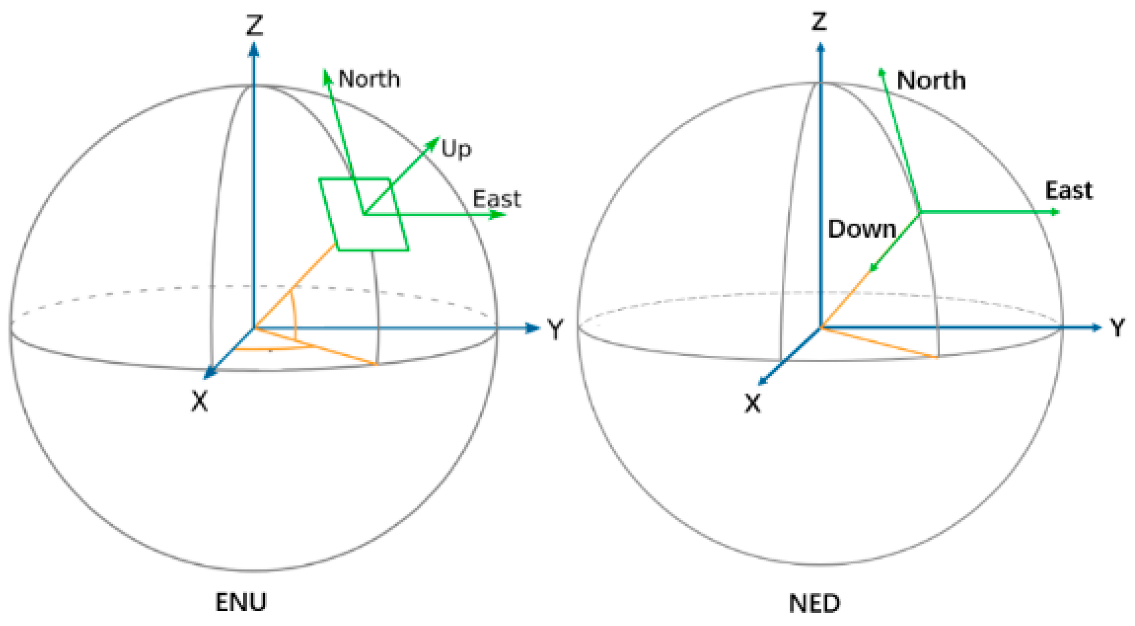
3.2.2. Northeast Sky Coordinate System and Northeast Earth Coordinate System
The Northeast Sky (NEZ) coordinate system and North-East-Down (NED) coordinate system are local coordinate systems used to represent coordinates in a Cartesian format centered around a specified reference point. In the Northeast Sky coordinate system, the X-axis points to the east, the Y-axis points to the north, and the Z-axis points upwards. In the North-East-Down coordinate system, the X-axis points to the north, the Y-axis points to the east, and the Z-axis points downward. In the case of drone oblique photography, the attitude of the drone’s gimbal-mounted camera is expressed by three angles: yaw, pitch, and roll. The yaw angle refers to the rotation around the Z-axis in the North-East-Down coordinate system, measured clockwise from the drone’s perspective. The pitch angle refers to the rotation around the Y-axis, also clockwise, and the roll angle refers to the rotation around the X-axis, again clockwise. These three angles, as illustrated in
Figure 2, define the orientation of the drone’s camera during image capture.
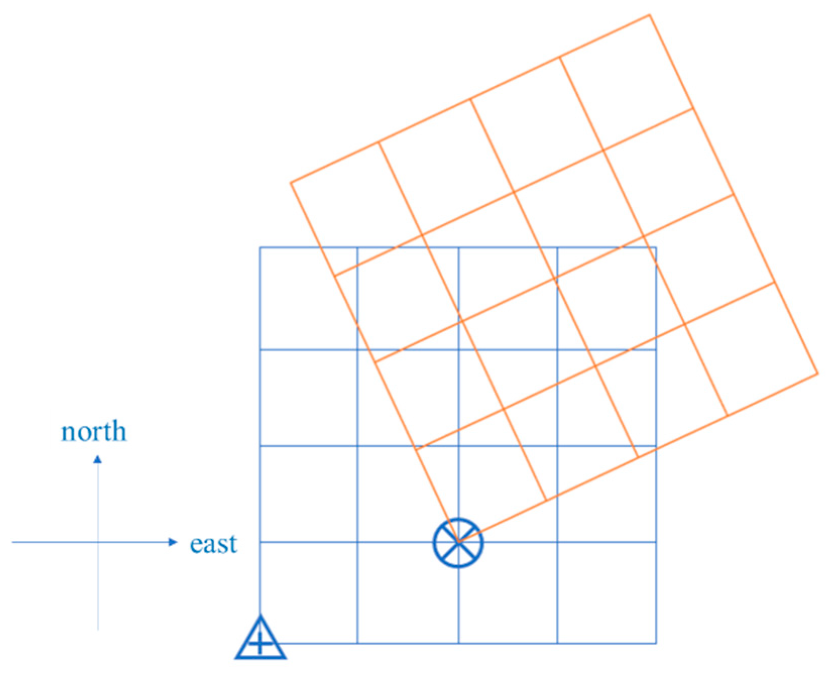
3.2.3. Revit Software Coordinate System
In Revit, the BIM model also has coordinate information, which is divided into survey coordinate systems and project coordinate systems based on different reference points.
1. Survey Coordinate System: This coordinate system is defined outside the project’s associative environment and can be used to identify the location of the Revit model on the Earth’s surface. In Revit, the survey point of the project coordinate system is represented by
![Drones 09 00215 i001]()
. Based on the definition of the Northeast Sky (NEZ) coordinate system, the Revit survey coordinate system is essentially a Northeast Sky coordinate system with the project survey point as the origin.
2. Project Coordinate System: This coordinate system describes the location relative to the building BIM model. It uses reference points selected from the boundary of the project or the project’s scope, and measures distances relative to model objects. The project coordinate system is represented by
![Drones 09 00215 i002]()
. The origin of the BIM model is at the project origin, with the X-axis pointing to the model’s true east (which differs from true east in the real world), the Y-axis pointing to the model’s true north, and the Z-axis pointing upward in the direction defined as “sky” by the model. Essentially, the project coordinate system can be viewed as the Northeast Sky coordinate system of the real world but transformed into the BIM model’s coordinate system through translation and rotation. The coordinate system used in Revit is illustrated in
Figure 3.
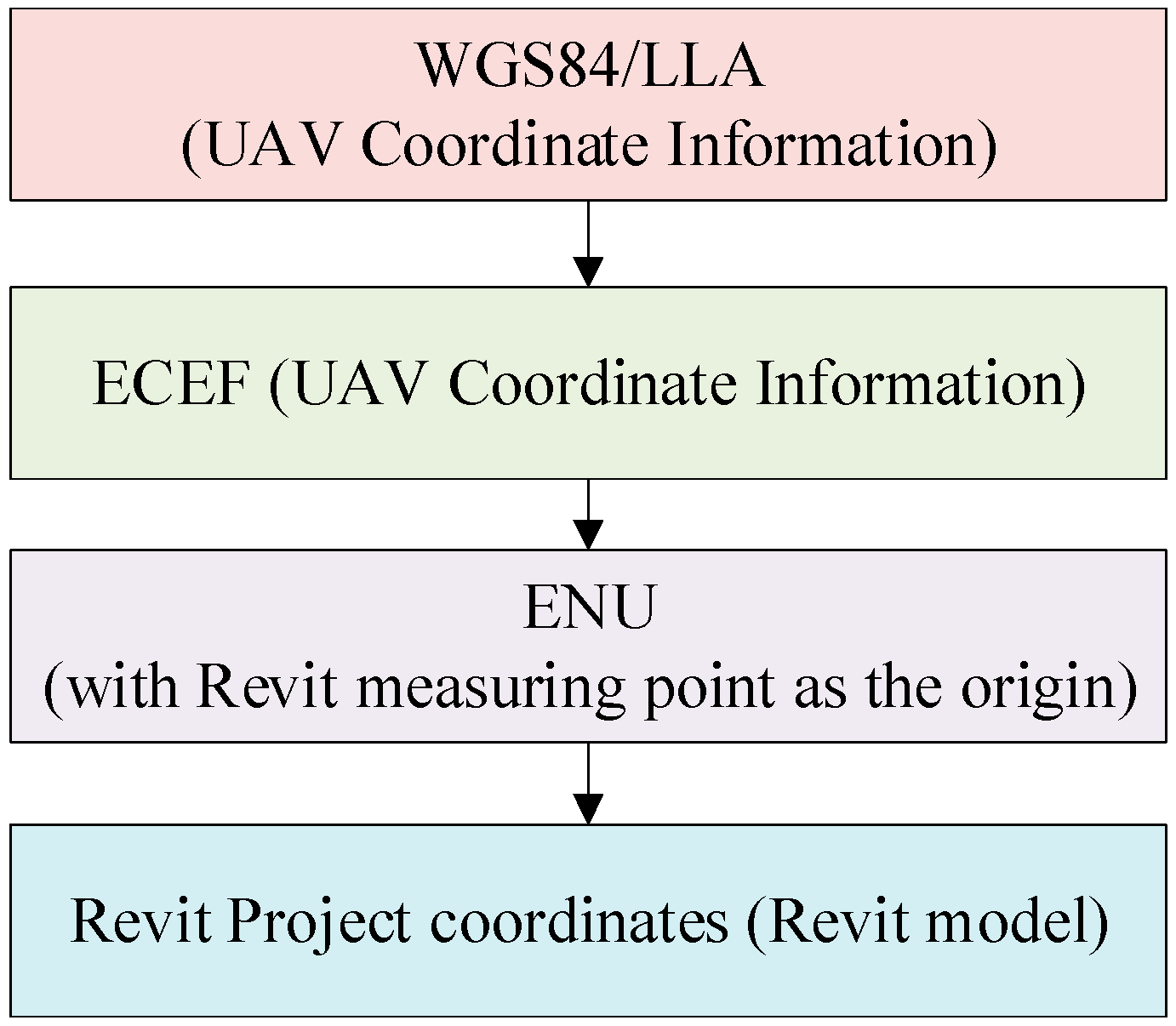
3.3. Drone Location Coordinates to REVIT Project Coordinates
Through the study of coordinate systems, it can be concluded that the steps for transforming the drone’s GPS position data into Revit project coordinates are as follows: First, the geodetic coordinates (latitude, longitude, and altitude) are converted into Earth-Centered, Earth-Fixed (ECEF) coordinates. Then, these coordinates are transformed into Northeast Sky coordinates with the Revit survey point as the origin. Finally, the coordinates are converted into Revit project coordinates. The flow chart for this process is shown in
Figure 4.
3.3.1. Longitude and Latitude Coordinates to Earth-Fixed Cartesian Coordinates
The geodetic coordinates (latitude, longitude, and altitude) can be transformed into Earth-Centered, Earth-Fixed (ECEF) coordinates based on the WGS84 ellipsoid parameters. The semi-major axis of the Earth is
a = 6,378,137 m, the semi-minor axis is
b = 6,356,752.314 m, and the flattening factor is
f = 1/298.257223563. The first eccentricity
e of the Earth is calculated as follows:
The latitude of the drone is lat, and the curvature radius
N of the reference ellipsoid is:
The longitude of the drone is lon, the elevation is alt, and the ground-fixed Cartesian coordinate
of the drone can be calculated:
3.3.2. The Northeast Sky Coordinates from the Fixed Cartesian Coordinates to the Specified Origin
After specifying the origin of the North-East-Down (NED) coordinate system, the transformation from Earth-Centered, Earth-Fixed (ECEF) coordinates to NED coordinates involves both the rotation and translation of the two Cartesian coordinate systems. The origin is shifted from the Earth’s center of mass to the origin of the NED coordinate system, and the axes (XYZ) are rotated to align with the Northeast Sky directions at that point.
In the ECEF coordinate system, the axes are represented as X
ecef, Y
ecef, Z
ecef. In the NED coordinate system, the axes are X
enu, Y
enu, Z
enu. The specified coordinate origin is point
P, with geodetic coordinates (
lonp,
latp,
altp). The ECEF coordinates of point
P are (
Xp,
Yp,
Zp). The translation part corresponds to converting the geodetic coordinates of point
P into ECEF coordinates (
Xp,
Yp,
Zp). The ECEF coordinates of point
R are (
Xr,
Yr,
Zr). The corresponding coordinates of point
R in the NED coordinate system, with
P as the origin, are given by the following equations:
3.3.3. Northeast Sky Coordinates to Revit Project Coordinates
The Revit project coordinates and the survey coordinates are related by both translation and rotation. Therefore, in order to accurately convert the coordinates of the drone’s image into Revit coordinates, it is necessary to consider the relative position between the survey coordinate system and the Revit coordinate system. Since both coordinate systems have their Z-axis pointing upwards (towards the sky), only the X and Y coordinates need to be transformed. The transformation method is as follows:
In this context, θ represents the clockwise rotation angle of the project coordinate system relative to the true north direction. xn and yn are the direction vectors of the drone image in the Revit project coordinate system, while xm and ym correspond to the coordinates in the survey coordinate system. x0 and y0 denote the coordinates of the project origin in the survey coordinate system.
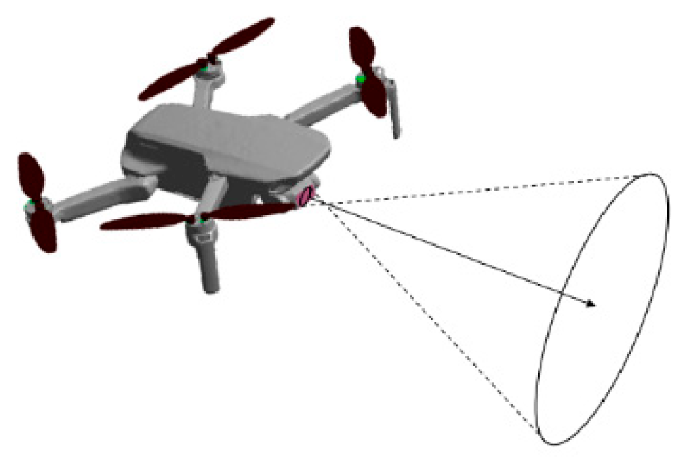
3.4. PTZ Camera Attitude Angle to Revit Direction Vector
The heading angle refers to the rotation angle in the North-East-Down (NED) coordinate system, determined by the direction of the line of sight from the center of the image sensor to the center of the field of view. By converting the gimbal camera’s attitude angle data into a direction vector within the BIM model, the relative orientation of the image within the BIM model can be determined, indicating the direction toward the BIM component corresponding to the drone’s image. A schematic diagram illustrating the drone’s capture direction is shown in
Figure 5.
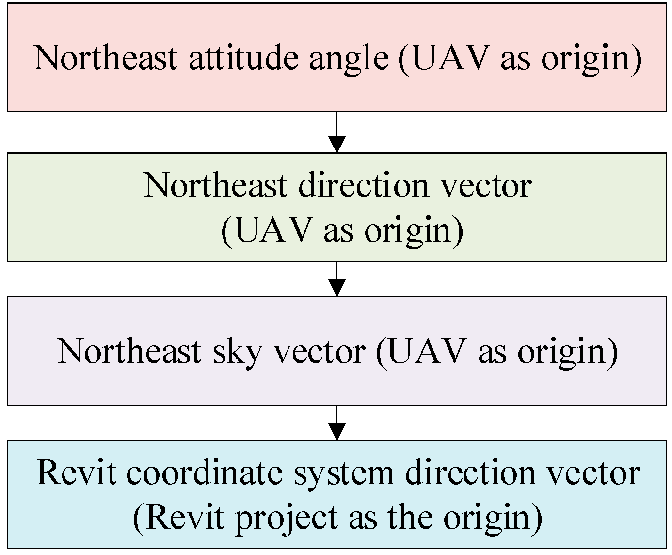
Since the attitude angles of the drone’s gimbal camera are defined as the rotation angles around the XYZ axes in the North-East-Down (NED) coordinate system, with the drone itself as the reference point, the steps to convert the gimbal’s attitude angles into vector coordinates in the Revit project coordinate system are as follows: First, the attitude angle data are converted into a direction vector in the North-East-Down coordinate system with the drone as the reference point. Next, the direction vector in the North-East-Down coordinate system is transformed into a direction vector in the North-East-Up (NEU) coordinate system, with the drone again as the reference point. Finally, after the translation and rotation from the North-East-Up coordinate system, the direction vector relative to the drone’s position is obtained in the Revit project coordinate system. The camera attitude angle transformation process is illustrated in
Figure 6.
3.4.1. Head Attitude Angle to Direction Vector
The rotation sequence for the attitude angles of the drone’s gimbal camera is ZYX (yaw–pitch–roll). In aerial imagery, the drone must be in a level flight state to capture images, which means that the drone’s gimbal camera does not produce roll angle (roll) data, i.e., roll = 0. Therefore, only yaw and pitch angles are involved in the vector transformation process. Based on the definitions of yaw and pitch, the direction vector first undergoes yaw rotation, followed by pitch rotation, to obtain the final coordinates in the North-East-Down (NED) coordinate system. Thus, the direction vector coordinates are calculated as follows:
3.4.2. Northeast Earth Vector Coordinates to Northeast Sky Vector Coordinates
In the case where both the North-East-Down (NED) coordinate system and the North-East-Up (NEU) coordinate system share the same origin, the order of the XY coordinate axes is reversed, and the direction of the Z-axis is opposite. Therefore, the conversion of the gimbal camera’s attitude angles into coordinates in the North-East-Up (NEU) coordinate system with the drone as the reference point is as follows:
3.4.3. Northeast Day Vector Coordinates Are Converted to Revit Project Coordinate Vector
The transformation of the drone camera’s North-East-Up (NEU) direction vector coordinates and the drone’s position in the NEU coordinate system to the Revit coordinate system involves both translation and rotation, which are consistent with the changes undergone by the coordinates. Therefore, by substituting the NEU coordinate values (x, y, z) into Formula (5), the direction vector of the drone image in the Revit project coordinate system can be obtained, which points towards the BIM component corresponding to the drone image.
4. Drone Images–BIM Model Pairing Plugin Development
4.1. Development Mode
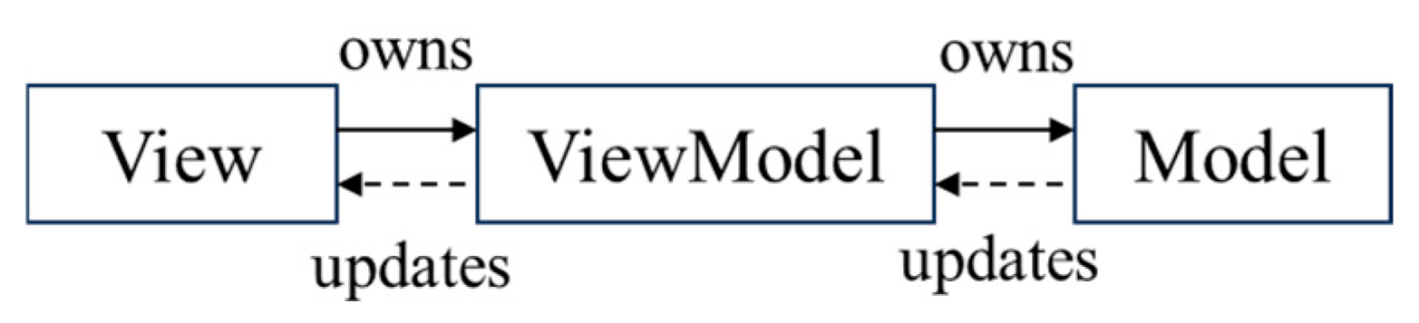
The Revit 2023 API was utilized for secondary development in this study, with the .NET framework version set to 4.7.2. To visualize and select the corresponding BIM components based on the drone’s relative position and orientation within Revit, C# was chosen for developing a WinForms application in Visual Studio. This application implements various functions, including the extraction of image POS data, coordinate transformation, visualization of the drone, and BIM component selection. Given the objectives, the MVVM (Model–View–ViewModel) development pattern was selected. In this pattern: the Model refers to the data model, which is used to store the data; the View represents the user interface (UI) and handles interaction requests; and the ViewModel is the core of the MVVM pattern, linking the Model and View by providing data logic and facilitating the transformation between them. The ViewModel operates in two directions: first, transforming the Model into the View, i.e., converting backend image data into the visible interface; and second, transforming the View into the Model, i.e., converting the visible interface into backend data. The data flow within the MVVM pattern is shown in
Figure 7.
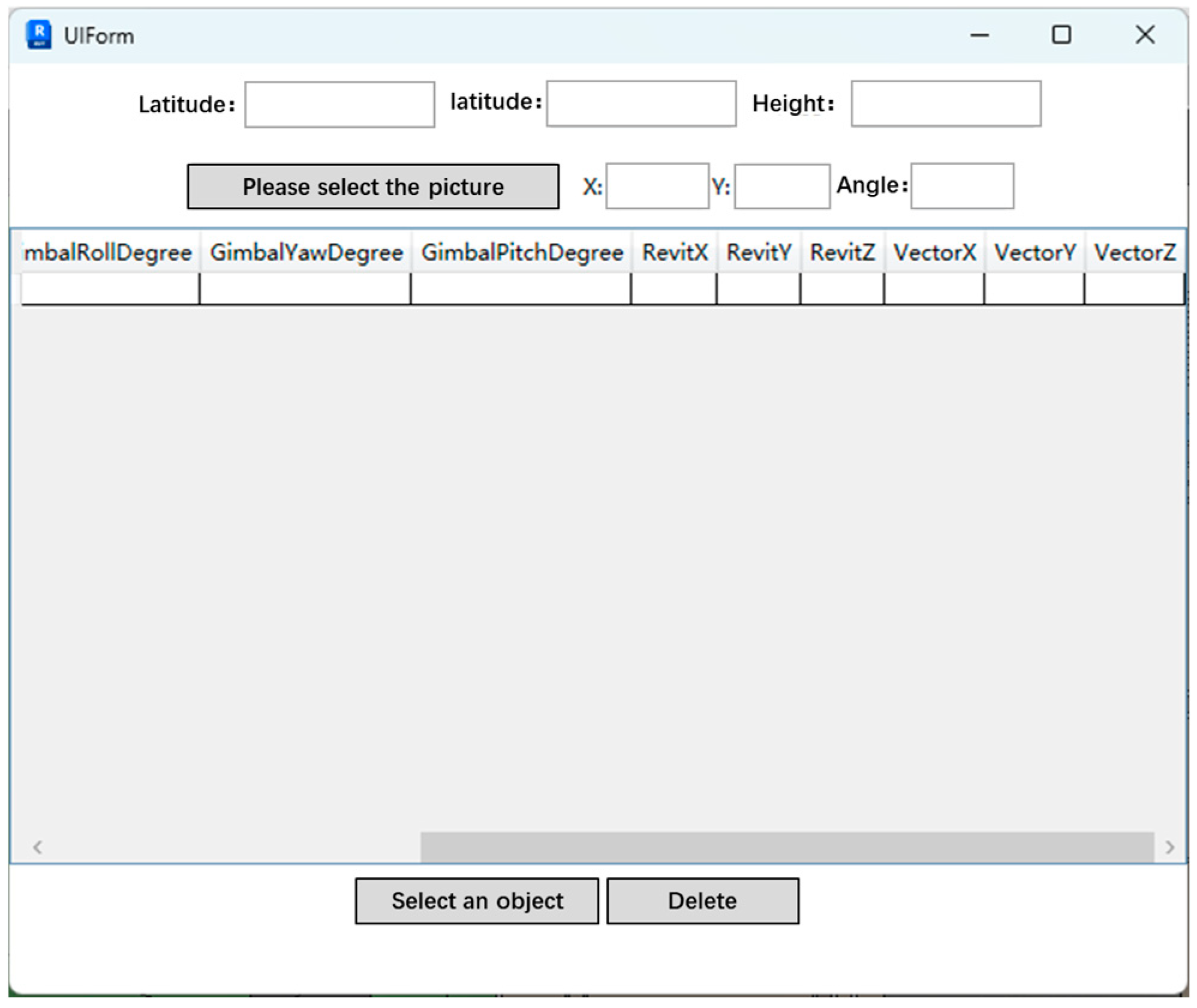
(1) The View refers to the Revit plugin UI interface created using WinForms, which includes UI elements such as tables and button controls. The functionalities provided by the View primarily include the following: input for surveying point latitude, longitude, and altitude data, coordinate system rotation angles, image data input, the display of image data in tables, and the selection and deletion of BIM components. The design of the UI interface for the View is shown in
Figure 8.
(2) The Model refers to the table data of the images in the UI View and the metadata stored in the drone images.
(3) The ViewModel provides logical support for functions such as adding image data, selecting BIM components, and deleting graphical elements and image data. This is implemented by calling upon the compiled helper functions. The helper classes used in this study are divided into three types:
① Commons (Common Class), which includes methods for creating drone and ray families, image metadata extraction methods, image data transformation methods, external event encapsulation methods, and element filtering methods. The principles of image data extraction and transformation have been discussed in the previous chapter. The implementation of family creation and element filtering methods, which are mainly involved in Revit, will be studied in detail in the next section.
② Extends (Extension Class), which includes extension methods for family creation, conversion methods for radians, and extension methods for transaction processing.
③ Entry, which includes the program startup entry and command entry.
4.2. Development Procedure
This paper first utilizes the Add-In Manager plugin to add applications from the IExternal Command interface-derived classes and develops the functionality using external commands for validation. Once the expected functionality is achieved, it will be loaded into Revit as an external application plugin. The main steps of the functionality development are as follows:
(1) Create a new project: A new C# Windows Forms application is created in Visual Studio 2023, with the output type set to a class library.
(2) Add Revit API assembly files RevitAPI.dll and RevitAPIUI.dll from the Revit SDK.
(3) Reference the external commands.
(4) Compile the functional code: data extraction, coordinate transformation, family creation, element filtering, etc.
(5) Generate the .dll file and load it into Revit 2023 through the Add-In Manager.
(6) Use Revit Lookup to check the properties of the family files and determine whether the functionality has been implemented. If not, debug the code and reload it. If the functionality has been implemented, the development is complete.
4.3. BIM Visual Selection Function Is Realized
4.3.1. Revit Ray Method
The “ReferenceIntersector” class provided by the Revit API enables the identification of elements, either individually or collectively, along a ray. This class offers four constructors, and the one utilized in this study requires the following parameters: “ElementId” (representing the element identifier), “FindReferenceTarget” (the target object type), and View3D (the 3D view). The drone’s positional and orientation data in this work satisfy the basic requirements for “raycasting”. In the context of building maintenance and management using drones, the images captured are typically associated with the exterior components of a building or structure (e.g., walls, doors, windows). Consequently, by invoking the “FindNearest()” method of the “ReferenceIntersector” class and inputting the relevant Revit coordinates and direction vector, the nearest BIM component along the ray can be accurately identified.
4.3.2. Element Filtration Method
To enhance the accuracy of the “raycasting” method and improve the program’s efficiency, element filtering is applied to the nearest family element detected along the ray. In Revit, most objects inherit from the element class, which consists of two primary components: the element header and the element content. The element header contains fundamental information, such as the “ElementId” and “CategoryId”, while the element content includes detailed data, such as geometry and parameters. The “Collector” class is commonly used to search for elements across the entire Revit document and is frequently employed for filtering operations. The “Collector” class offers three constructors, each returning different sets of elements based on the input variables provided.
In this study, only essential information, such as the name and category of the selected family element (i.e., the element header), is required. As a result, a rapid filter is applied to the element set. For the specific needs of this study, filtering is applied exclusively to four types of elements: doors, windows, walls, and columns. For other engineering applications, the filter can be customized by adding or removing element types according to the requirements of the task at hand.
4.3.3. BIM Visual Selection
The element-filtering and “raycasting” processes can quickly yield results, such as the BIM component selected by the “raycasting” method. However, the entire process cannot be visually represented within the model, which makes it challenging for developers and maintenance personnel to intuitively assess the output. To facilitate the verification of the drone’s position and ray direction, it is essential to visualize the selection of BIM components by the drone. The solution proposed in this study involves loading a drone family at the BIM coordinates corresponding to the drone’s position and a ray family at the same coordinates along the ray’s direction. This approach enables the visualization of the drone’s position and orientation, as well as the relative location of the actual building, within Revit. Furthermore, the BIM component selected by the “raycasting” method is highlighted using a bounding box, allowing developers and maintenance personnel to rapidly verify the accuracy of the selected BIM component.
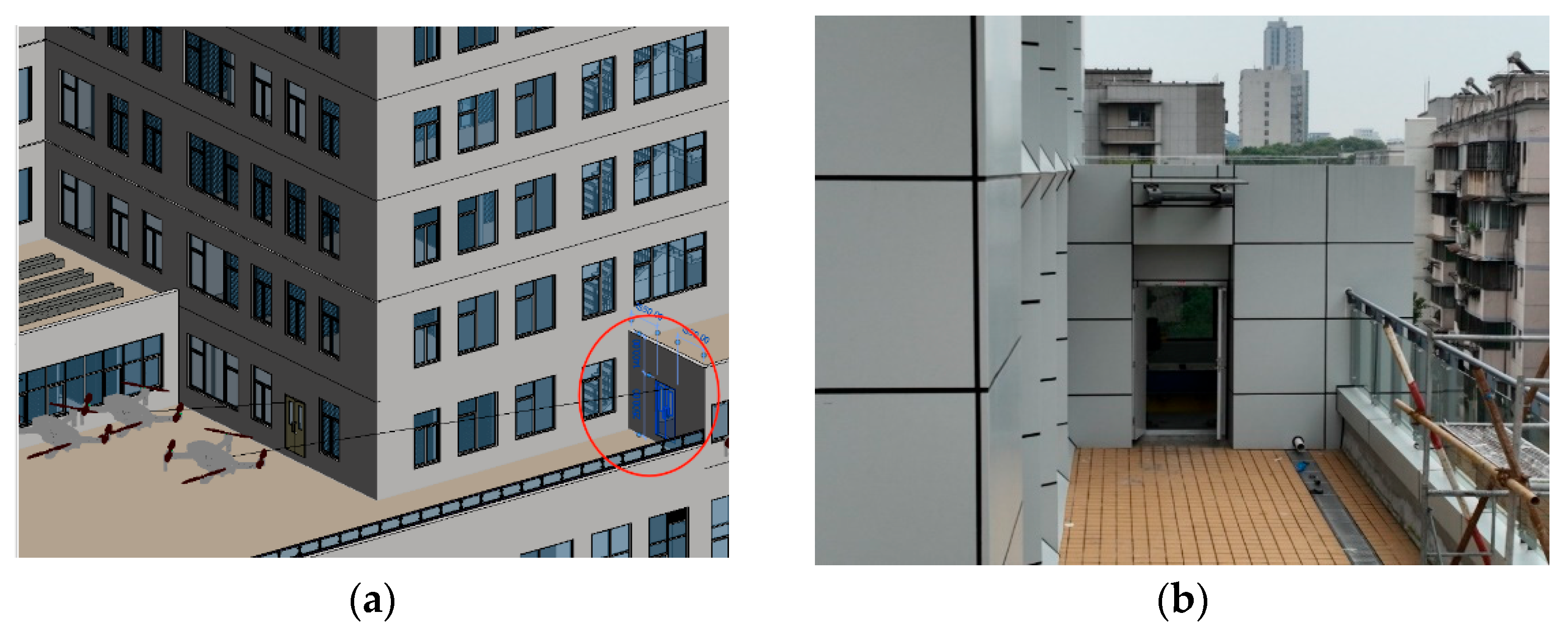
5. Case Study
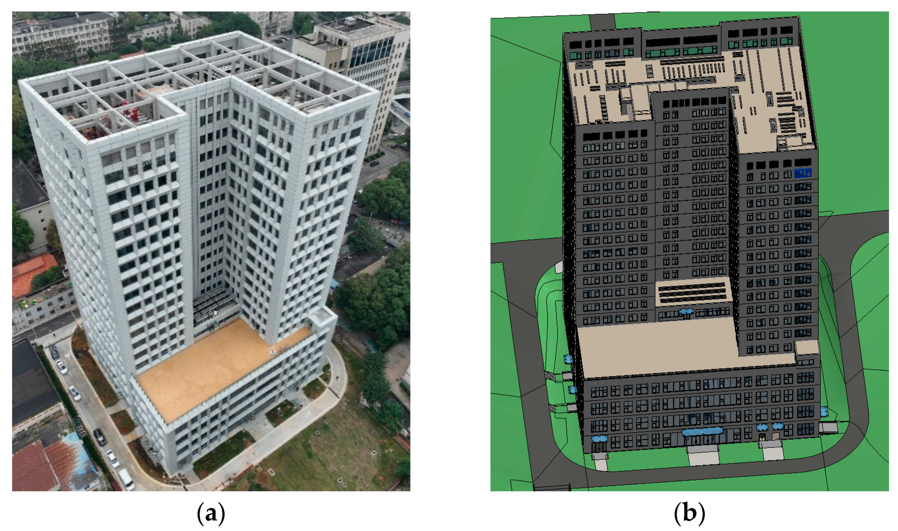
A high-rise office building was selected as the case study for validation in this research, as shown in
Figure 9. The total building area is 133,872.9 m
2, with a height of 81.52 m and 18 floors. The building was completed and put into use in 2023. Its main structural system consists of a frame shear wall structure, and the exterior wall insulation layer is made of adhesive materials.
5.1. Basic Data Collection
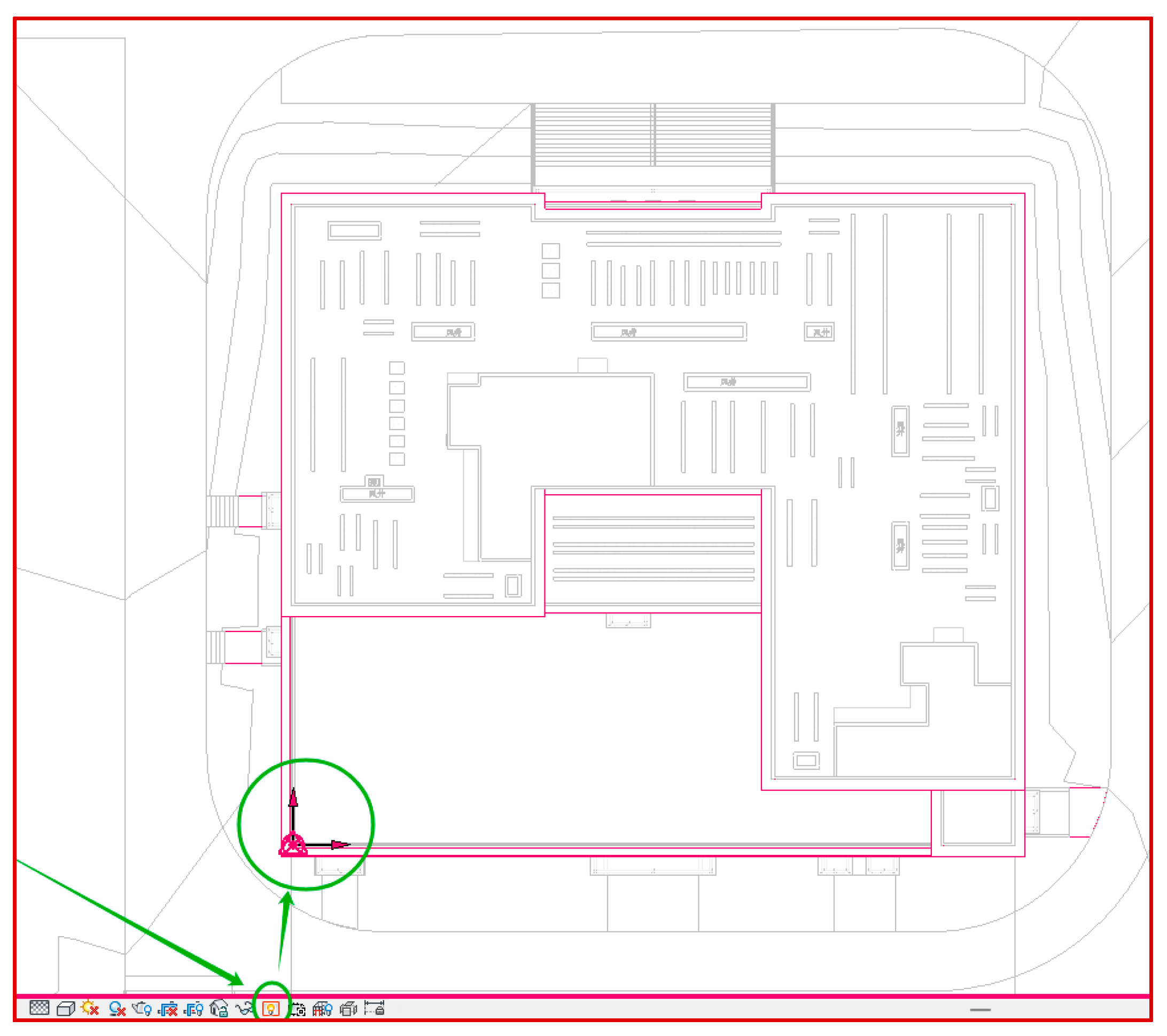
5.1.1. Coordinate Origin Data Collection
The BIM model for this project does not include the geographic coordinates of the project origin, and therefore, the base coordinate data cannot be automatically retrieved in Revit. In this study, an RTK (Real-Time Kinematic) surveying instrument was used for control measurements. The latitude of the Revit project origin was determined to be 30.522660991° N, and the longitude was 114.343412461° E. The clockwise angle between the Y-axis of the Revit survey coordinate system and true north was found to be 0.912°. The building’s coordinate origin is shown in
Figure 10.
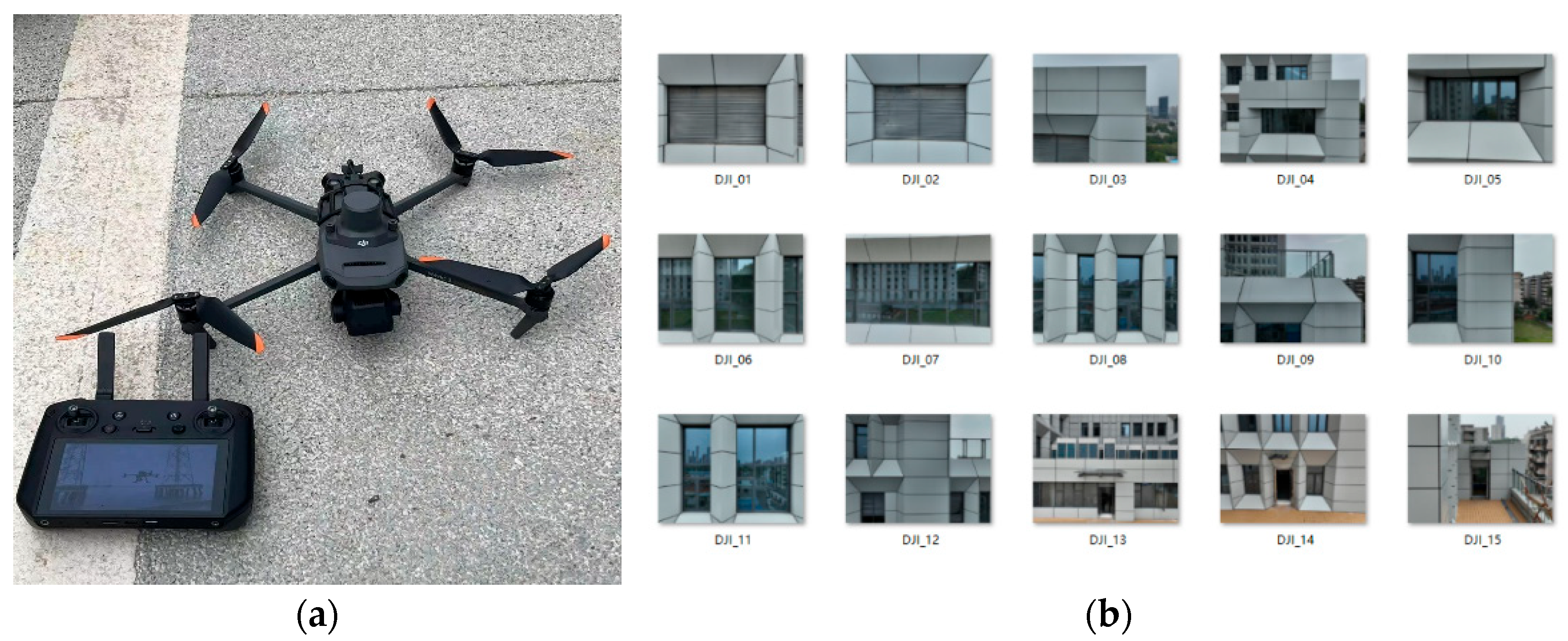
5.1.2. Drone Image Data Acquisition
In this study, a DJI Matrice 300 RTK drone manufactured by DJI (Shenzhen, China) and equipped with an RTK module was used to capture images of the building components of the project. The image targets were representative exterior elements of the building, including doors, windows, and walls. The selected components were chosen to ensure distinguishability, and multiple directions and angles were covered. To validate the accuracy of the drone image-to-BIM model matching method, two types of drone images were collected: (1) images of different building components captured from the same direction at approximately the same hovering position and (2) images of different building components captured from various directions at approximately the same hovering position. To ensure the precision of the drone images, the RTK functionality was required to be active during the operation, and the drone needed to hover stably with the building components positioned at the center of the image. Ultimately, 15 drone images were obtained, as shown in
Figure 11.
5.2. Image Input and Coordinate Transformation
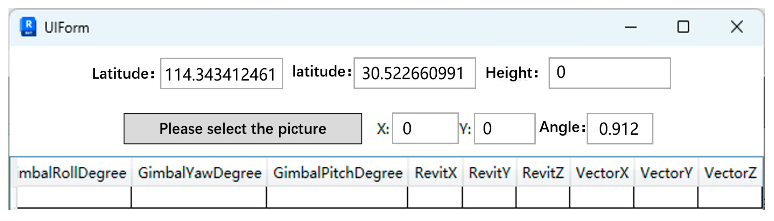
5.2.1. Image Data Entry
In Revit 2023, the building BIM model is loaded, and the interface bar is set to the 3D view. The plugin developed in this study is automatically loaded along with Revit and displayed in the functionality toolbar. By clicking on the toolbar, the plugin’s UI Form interface pops up, as shown in
Figure 12. The user can then enter the collected coordinate base information. By clicking on “select the image you need”, the user can choose the drone image from the storage path on the computer, which will then be input into the system.
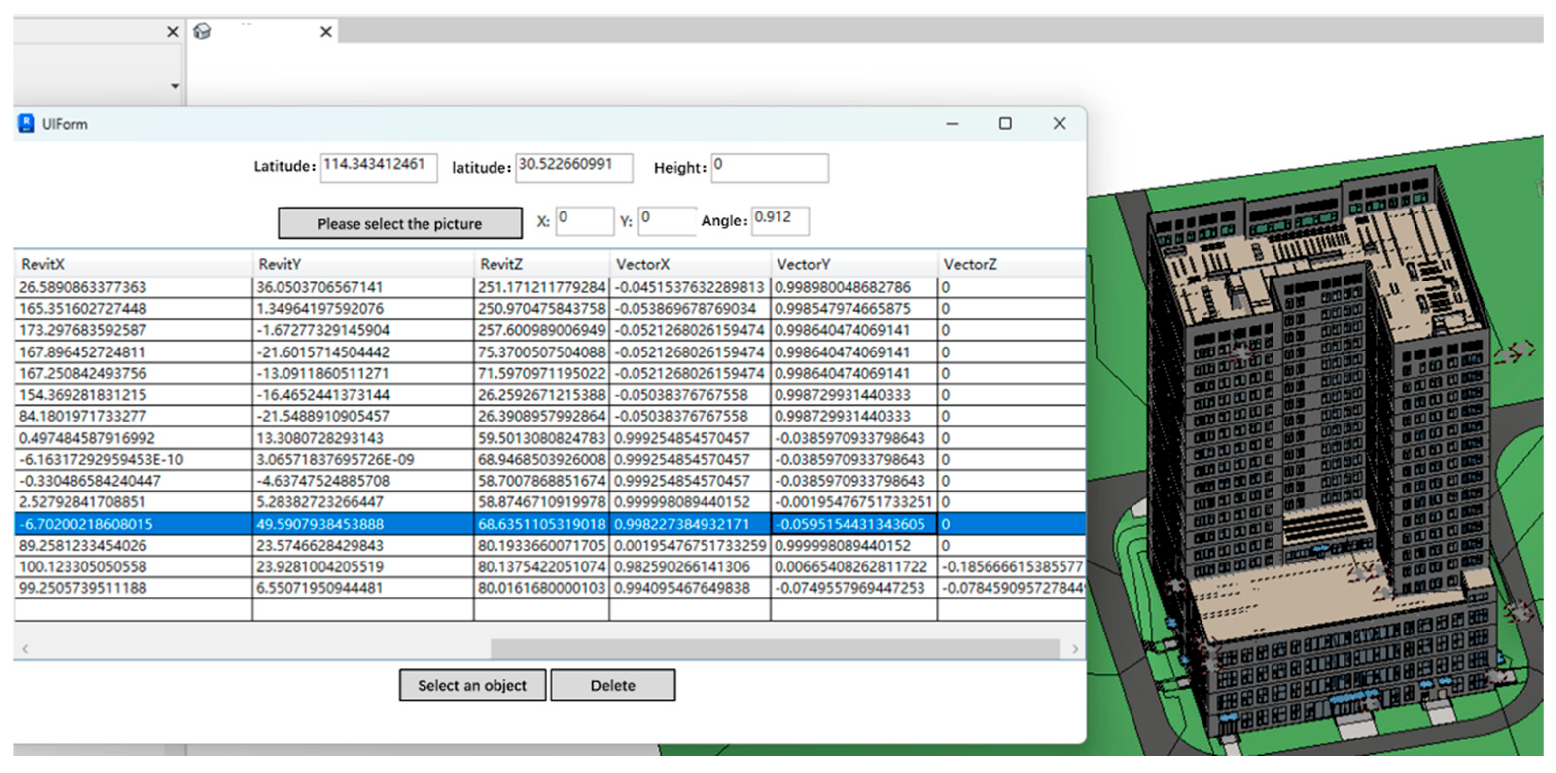
5.2.2. Coordinate Extraction and Transformation
After the image is input, the POS data extracted from the image are displayed in the WinForm-created view interface. The coordinate data, once converted into Revit coordinates, are also output as table data in the UI interface, as shown in
Figure 13.
5.3. Visual Result Verification
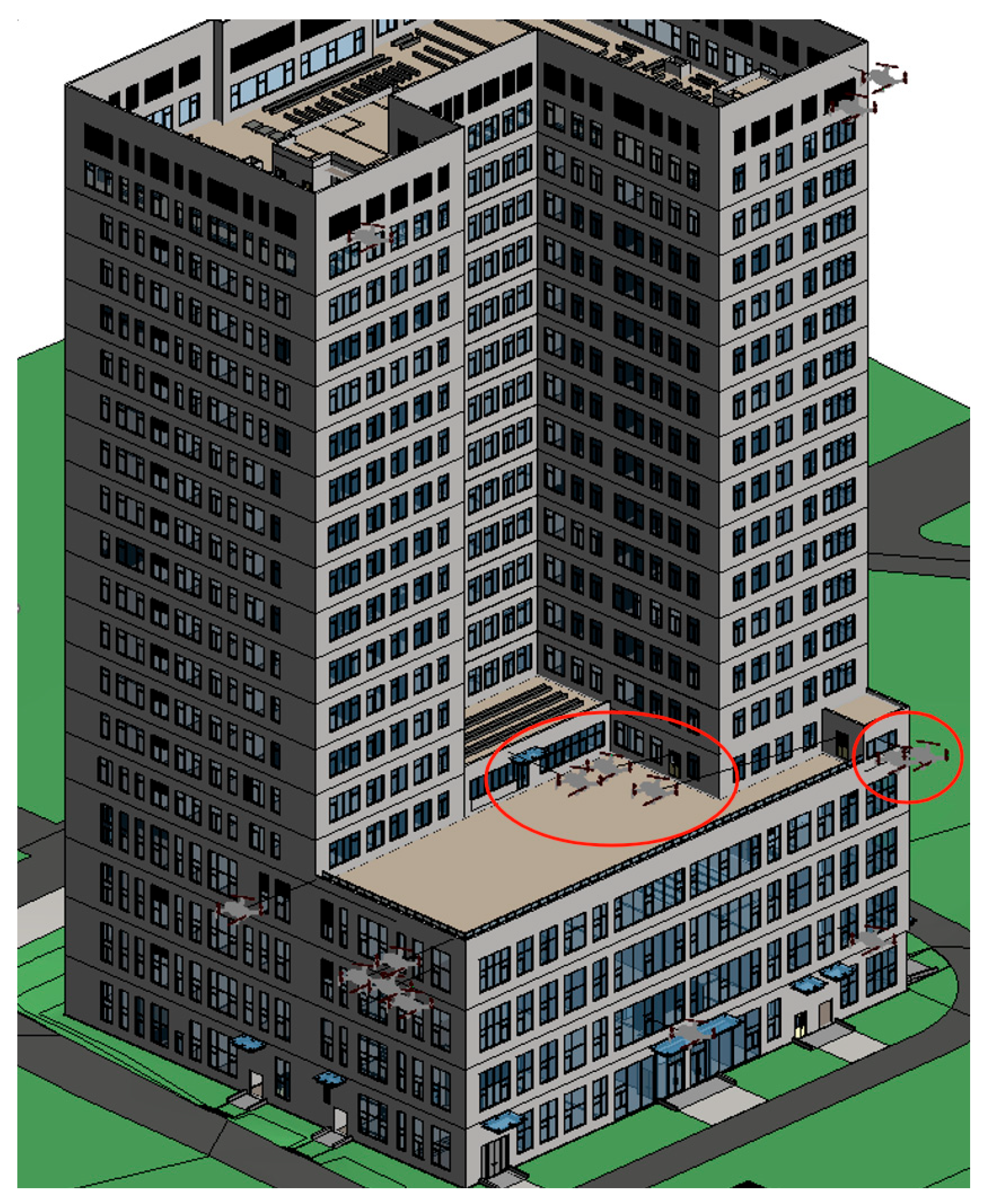
After the POS data collected by the drone are converted into Revit project coordinates, the drone family in Revit is generated in the Revit model’s view based on the Revit coordinate data. The corresponding ray family of the drone is created at the drone’s coordinates and points in the direction indicated by the direction vector, selecting the nearest BIM component along the ray. To better display the drone family’s position in the 3D view of the building’s BIM model, the scale factor of the drone family is set to 10 (i.e., the relative size of the drone’s volume in Revit is 10 times that of the original drone). The Revit view is shown in
Figure 14.
Once the drone and its ray are placed within the BIM model, the system then identifies and selects the nearest BIM component along the ray’s trajectory. This component is matched with the drone’s position and orientation based on the POS data, creating a spatial alignment between the captured image and the corresponding BIM component. At this point, the system does not automatically open the image in the view, but instead, the user can manually select the corresponding BIM component (such as a door, window, or wall) and retrieve the associated drone image. The image, previously uploaded into the system and stored with metadata, is linked to this BIM component. The file name of the image is used to reference the specific image captured by the drone. This allows the user to view the image manually through the interface by clicking the BIM component associated with the image.
5.4. BIM Component Selection Visualization
After confirming that the drone and ray are correctly generated in Revit, the next step is to verify whether the BIM component selected by the ray corresponds to the real building component indicated by the image. By clicking the “select an object” button in the UI interface and selecting the drone object, it is possible to check whether the drone has correctly selected the corresponding building component. Taking the image with the filename “DJI_15.JPG” as an example, the selection result is shown in
Figure 15, where the ray selects the family component “M_Double Leaf Fire Door FM Jia 1221”. By comparing it with the original image in the folder, it can be concluded that the drone family- and ray family-selected Revit family (i.e., the BIM component) is indeed the building component captured in the image. This method is then applied for successive comparisons and analyses of the drone families in Revit.
In this process, once the BIM component is selected by the ray, the system retrieves the image file associated with that component, based on the metadata that were input during the image data entry phase. The image file is accessed manually through the interface, allowing the user to confirm that the drone-captured image corresponds to the identified BIM component. The file name of the image (e.g., “DJI_15.JPG”) is stored and used as a reference to match the selected BIM component with its respective image. By visually comparing the image with the building component in the BIM model, the user can confirm whether the image aligns with the selected model element. This manual interaction ensures that the image is correctly paired with the BIM component.
In practice, this technology would be integrated into building maintenance workflows, where drone data are collected and automatically matched with BIM components. Maintenance teams would use an intuitive interface to verify the automated matches by visually comparing the drone images with the corresponding model elements. While the system automates much of the pairing process, human operators would oversee the results, ensuring accuracy and making adjustments if needed. This capability would be especially useful during routine inspections or for addressing specific maintenance tasks, enabling a more efficient and precise monitoring of building conditions.
5.5. Future Compatibility and Development Strategy
The developed plugin can maintain compatibility with future versions of Revit. In the event of significant API changes, code refactoring will be conducted to ensure the accuracy of its core functions, such as coordinate transformation and image-to-BIM matching. The plugin’s long-term compatibility and usability are supported by the implementation of a modular code structure. Its modular architecture allows for targeted updates without affecting the entire system. This development strategy not only ensures compatibility with advancing software versions but also enhances the plugin’s potential for integration into broader building management and inspection workflows. Future development efforts will focus on enhancing its automation and improving the user interface, including integrating advanced image recognition technologies to refine BIM component identification. Additionally, the possibility of extending its compatibility to other BIM platforms will be explored to broaden its application in building inspection and maintenance.
6. Conclusions
This study presents a method for integrating drone images with BIM models, automating the pairing of drone-captured images with corresponding BIM components for efficient building inspection and maintenance. The method converts GPS coordinates and camera orientation data from drone images into relative position and directional coordinates in the BIM model, ensuring precise spatial and directional alignment. The Revit-based plugin developed using Visual Studio 2022, C#, and WinForms facilitates key functions such as data extraction, coordinate conversion, ray tracing, element filtering, and the visualization of BIM components. The system was validated through a case study of a high-rise office building, demonstrating its ability to accurately pair drone images with building components, such as doors, windows, and walls.
The proposed method offers significant improvements over traditional building inspection techniques. Unlike manual inspections that rely on visual assessments and are prone to human error, our approach automates the process, enabling faster, more accurate, and cost-effective inspections. The main advantages of the method are as follows:
1. Efficiency: It significantly reduces inspection times by automating the matching of large volumes of image data to the BIM model, particularly useful for complex buildings where manual searches would be time-consuming.
2. Accuracy: By leveraging precise drone data and coordinating them with the BIM model, the method ensures reliable component identification, overcoming human error in traditional methods.
3. Cost-Effectiveness: Automation reduces the need for extensive labor and minimizes errors, lowering the operational costs associated with traditional inspection methods.
4. Practical Application: The case study demonstrates the method’s practical viability, confirming that drone images can be successfully paired with BIM components in real-world building maintenance and management scenarios.
This technology not only demonstrates great potential for applications in the external maintenance of high-rise buildings, but it also holds promise for widespread use in the operation and maintenance phases of other large-scale projects such as industrial plants, bridges, and sports stadiums. By achieving the efficient pairing of images with BIM components, building maintenance can become more automated and precise, reducing labor costs and improving safety. Moreover, this method provides the potential for the intelligent monitoring and data management of more complex structures in the future, offering scientific support and decision-making assistance for the long-term operation and management of buildings.
Author Contributions
Conceptualization, S.H.; methodology, S.H.; software, X.H.; validation, X.H.; formal analysis, Z.D.; investigation, Z.D.; resources, J.H.; data curation, J.H.; writing—original draft preparation, J.H.; writing—review and editing, J.H.; visualization, W.C.; supervision, W.C.; project administration, W.C.; funding acquisition, L.C. All authors have read and agreed to the published version of the manuscript.
Funding
This research was funded by the special research and development plan of the China Construction Seventh Engineering Division Co., Ltd. (Grant No. CSCEC7b-2023-Z-19).
Data Availability Statement
The original contributions presented in this study are included in the article; further inquiries can be directed to the corresponding author.
Conflicts of Interest
Authors Shaojin Hao, Xinghong Huang, and Zhen Duan are working for the company CSCEC 7th Division International Engineering Co., Ltd. The remaining authors declare that the research was conducted in the absence of any commercial or financial relationships that could be construed as a potential conflict of interest.
References
- de Souza, I.T.; Patriarca, R.; Haddad, A. Resilient performance in building maintenance: A macro-cognition perspective during sudden breakdowns. Appl. Ergon. 2024, 118, 14. [Google Scholar] [CrossRef] [PubMed]
- Garrido, M.A.; Paulo, P.V.; Branco, F.A. Service life prediction of facade paint coatings in old buildings. Constr. Build. Mater. 2012, 29, 394–402. [Google Scholar] [CrossRef]
- Hegazy, T.; Gad, W. Dynamic System for Prioritizing and Accelerating Inspections to Support Capital Renewal of Buildings. J. Comput. Civil. Eng. 2015, 29, 8. [Google Scholar] [CrossRef]
- Lee, S.; Kang, M.S.; Han, C.S. Sensor Based Motion Planning and Estimation of High-rise Building Facade Maintenance Robot. Int. J. Precis. Eng. Manuf. 2012, 13, 2127–2134. [Google Scholar] [CrossRef]
- Jiao, Z.D.; Du, X.L.; Liu, Z.S.; Liu, L.; Sun, Z.; Shi, G.L. Sustainable Operation and Maintenance Modeling and Application of Building Infrastructures Combined with Digital Twin Framework. Sensors 2023, 23, 33. [Google Scholar] [CrossRef]
- Jiao, Z.D.; Du, X.L.; Liu, Z.S.; Liu, L.; Sun, Z.; Shi, G.L.; Liu, R.R. A Review of Theory and Application Development of Intelligent Operation Methods for Large Public Buildings. Sustainability 2023, 15, 28. [Google Scholar] [CrossRef]
- Ismail, Z.A. Improving conventional method on precast concrete building maintenance Towards BIM implementation. Ind. Manage. Data Syst. 2017, 117, 1485–1502. [Google Scholar] [CrossRef]
- Kameli, M.; Hosseinalipour, M.; Sardroud, J.M.; Ahmed, S.M.; Behruyan, M. Improving maintenance performance by developing an IFC BIM/RFID-based computer system. J. Ambient Intell. Humaniz. Comput. 2021, 12, 3055–3074. [Google Scholar] [CrossRef]
- Villa, V.; Bruno, G.; Aliev, K.; Piantanida, P.; Corneli, A.; Antonelli, D. Machine Learning Framework for the Sustainable Maintenance of Building Facilities. Sustainability 2022, 14, 17. [Google Scholar] [CrossRef]
- Wang, H.T.; Yu, C.Z.; Zheng, J.R.; Jia, Y.H.; Liu, Z.S.; Yang, K. Digital-Twin-Based Operation and Maintenance Management Method for Large Underground Spaces. Buildings 2024, 14, 18. [Google Scholar] [CrossRef]
- Banfi, F.; Roascio, S.; Mandelli, A.; Stanga, C. Narrating Ancient Roman Heritage through Drawings and Digital Architectural Representation: From Historical Archives, UAV and LIDAR to Virtual-Visual Storytelling and HBIM Projects. Drones 2023, 7, 31. [Google Scholar] [CrossRef]
- Pereira, R.C.C.; de Resende, P.N.; Pires, J.R.C.; Cuperschmid, A.R.M. BIM-enabled strategies for dams and hydroelectric structures: A comprehensive analysis of applications from design to operation. Archit. Eng. Des. Manag. 2024, 1–22. [Google Scholar] [CrossRef]
- Rizo-Maestre, C.; González-Avilés, A.; Galiano-Garrigós, A.; Andújar-Montoya, M.D.; Puchol-García, J.A. UAV plus BIM: Incorporation of Photogrammetric Techniques in Architectural Projects with Building Information Modeling Versus Classical Work Processes. Remote Sens. 2020, 12, 18. [Google Scholar] [CrossRef]
- Berrett, B.E.; Vernon, C.A.; Beckstrand, H.; Pollei, M.; Markert, K.; Franke, K.W.; Hedengren, J.D. Large-Scale Reality Modeling of a University Campus Using Combined UAV and Terrestrial Photogrammetry for Historical Preservation and Practical Use. Drones 2021, 5, 42. [Google Scholar] [CrossRef]
- Chen, K.W.; Reichard, G.; Akanmu, A.; Xu, X. Geo-registering UAV-captured close-range images to GIS-based spatial model for building facade inspections. Autom. Constr. 2021, 122, 13. [Google Scholar] [CrossRef]
- Chen, K.W.; Reichard, G.; Xu, X.; Akanmu, A. Automated crack segmentation in close-range building facade inspection images using deep learning techniques. J. Build. Eng. 2021, 43, 16. [Google Scholar] [CrossRef]
- Lemos, R.; Cabral, R.; Ribeiro, D.; Santos, R.; Alves, V.; Dias, A. Automatic Detection of Corrosion in Large-Scale Industrial Buildings Based on Artificial Intelligence and Unmanned Aerial Vehicles. Appl. Sci. 2023, 13, 24. [Google Scholar] [CrossRef]
- Nooralishahi, P.; Ibarra-Castanedo, C.; Deane, S.; Lopez, F.; Pant, S.; Genest, M.; Avdelidis, N.P.; Maldague, X.P.V. Drone-Based Non-Destructive Inspection of Industrial Sites: A Review and Case Studies. Drones 2021, 5, 29. [Google Scholar] [CrossRef]
- Zhao, Y.; Watanabe, J. A robust abnormal detection method for complex structures in UAV images for autonomous O&M system. In Proceedings of the Conference on Autonomous Systems—Sensors, Vehicles, Security, and the Internet of Everything, Orlando, FL, USA, 16–18 April 2018. [Google Scholar]
- Boddupalli, C.; Sadhu, A.; Azar, E.R.; Pattyson, S. Improved visualization of infrastructure monitoring data using building information modeling. Struct. Infrastruct. Eng. 2019, 15, 1247–1263. [Google Scholar] [CrossRef]
- Fang, T.C.; Zhao, Y.M.; Gong, J.; Wang, F.L.; Yang, J. Investigation on Maintenance Technology of Large-Scale Public Venues Based on BIM Technology. Sustainability 2021, 13, 18. [Google Scholar] [CrossRef]
- Guo, D.M.; Onstein, E.; La Rosa, A.D. An Approach of Automatic SPARQL Generation for BIM Data Extraction. Appl. Sci. 2020, 10, 17. [Google Scholar] [CrossRef]
- Hu, Z.Z.; Zhang, J.P.; Yu, F.Q.; Tian, P.L.; Xiang, X.S. Construction and facility management of large MEP projects using a multi-Scale building information model. Adv. Eng. Softw. 2016, 100, 215–230. [Google Scholar] [CrossRef]
- Ye, M.L. Application and Expression of BIM Technology in Industrial Building Reconstruction. In Proceedings of the International Workshop on Advances in Social Sciences (IWASS), Hongkong, China, 12–13 December 2018; pp. 472–478. [Google Scholar]
- Yoon, J.H.; Cha, H.S.; Kim, J. Three-Dimensional Location-Based O&M Data Management System for Large Commercial Office Buildings. J. Perform. Constr. Facil. 2019, 33, 13. [Google Scholar] [CrossRef]
- Zhao, X.F.; Li, M.X.; Sun, Z.; Zhao, Y.; Gai, Y.H.; Wang, J.J.; Huang, C.; Yu, L.; Wang, S.C.; Zhang, M.; et al. Intelligent Construction and Management of Landscapes through Building Information Modeling and Mixed Reality. Appl. Sci. 2022, 12, 15. [Google Scholar] [CrossRef]
- Tan, Y.; Li, S.L.; Liu, H.L.; Chen, P.L.; Zhou, Z.X. Automatic inspection data collection of building surface based on BIM and UAV. Autom. Constr. 2021, 131, 16. [Google Scholar] [CrossRef]
- Akinsemoyin, A.; Langar, S.; Awolusi, I. Framework for UAV-BIM Integration for Proactive Hazard Identification in Construction. In Proceedings of the 2nd Joint Conference of the Construction Research Congress (CRC)/Construction-Institute (CI) Summit, Iowa State University, Des Moines, IA, USA, 20–23 March 2024; pp. 697–706. [Google Scholar]
- Huang, X.W.; Liu, Y.P.; Huang, L.Z.; Stikbakke, S.; Onstein, E. BIM-supported drone path planning for building exterior surface inspection. Comput. Ind. 2023, 153, 21. [Google Scholar] [CrossRef]
- Strieder, H.L.; Lopes, J.M.; Weber, I.; Gorkos, P.; Isatto, E.L. Evaluation of the field survey procedure and three-dimensional modelling of a building using drone-captured images. Aust. J. Civ. Eng. 2023, 1–12. [Google Scholar] [CrossRef]
- Oliveira Sena, R.; Souza Silva, A.; Sávio Sampaio de Melo, R.; Bastos Costa, D. Proposal for integrating drone images and BIM in educational public buildings to support maintenance management. Rev. Ing. Construcción 2024, 39, 3. [Google Scholar] [CrossRef]
| Disclaimer/Publisher’s Note: The statements, opinions and data contained in all publications are solely those of the individual author(s) and contributor(s) and not of MDPI and/or the editor(s). MDPI and/or the editor(s) disclaim responsibility for any injury to people or property resulting from any ideas, methods, instructions or products referred to in the content. |
© 2025 by the authors. Licensee MDPI, Basel, Switzerland. This article is an open access article distributed under the terms and conditions of the Creative Commons Attribution (CC BY) license (https://creativecommons.org/licenses/by/4.0/).


 . Based on the definition of the Northeast Sky (NEZ) coordinate system, the Revit survey coordinate system is essentially a Northeast Sky coordinate system with the project survey point as the origin.
 . The origin of the BIM model is at the project origin, with the X-axis pointing to the model’s true east (which differs from true east in the real world), the Y-axis pointing to the model’s true north, and the Z-axis pointing upward in the direction defined as “sky” by the model. Essentially, the project coordinate system can be viewed as the Northeast Sky coordinate system of the real world but transformed into the BIM model’s coordinate system through translation and rotation. The coordinate system used in Revit is illustrated in Figure 3.
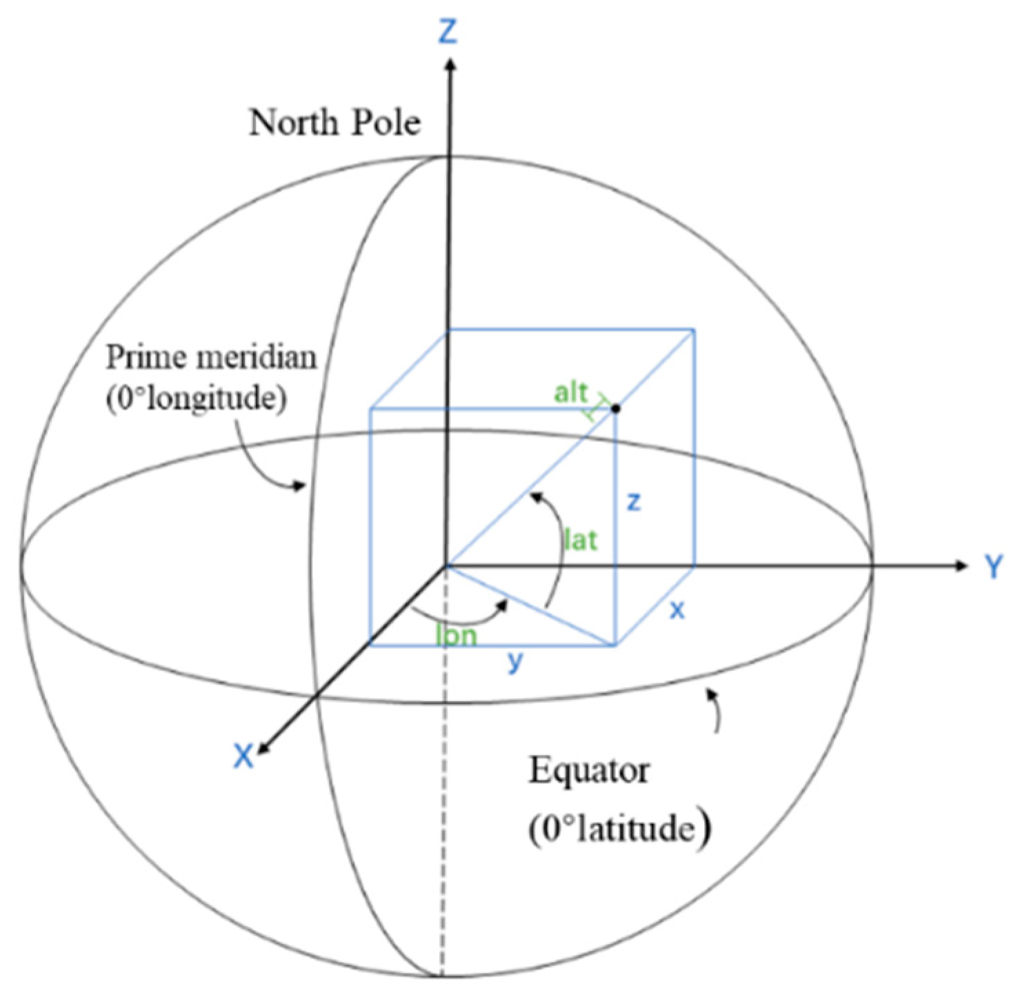
 represents the origin of the measurement coordinate system.
  represents the origin of the project coordinate system.