Article

An Improved Hybrid MRAC–LQR Control Scheme for Robust Quadrotor Altitude and Attitude Regulation

by
Abdelrahman A. Alblooshi
1,*,
Ishaq Hafez
2 and
Rached Dhaouadi
2
1
Mechatronics Graduate Program, College of Engineering, American University of Sharjah, Sharjah 26666, United Arab Emirates
2
Department of Electrical Engineering, College of Engineering, American University of Sharjah, Sharjah 26666, United Arab Emirates
*
Author to whom correspondence should be addressed.
Drones 2025, 9(12), 814; https://doi.org/10.3390/drones9120814
Submission received: 21 October 2025 / Revised: 17 November 2025 / Accepted: 18 November 2025 / Published: 24 November 2025

Highlights

What are the main findings?
  • A cascaded MRAC–LQR control scheme with integral action is proposed to improve the performance of the standard MRAC.
  • MRAC–LQR shows good robustness to disturbances and parameter variation, with a smoother response and faster settling time compared to MRAC–PID, which has large thrust spikes and rotor overspeed risk.
What are the implications of the main findings?
  • The cascaded MRAC–LQR achieves balanced stabilization for different quadrotor regulation scenarios, with faster transients, better disturbance rejection, and moderate control effort.
  • For implementation, integral action in LQR and thrust limiting help keep inputs within limits, while the adaptive branch compensates uncertainties and parameter changes.

Abstract

This paper presents the design and analysis of a hybrid Model Reference Adaptive Controller combined with a Linear Quadratic Regulator (MRAC–LQR) for a quadrotor unmanned aerial vehicle (UAV), addressing challenges posed by nonlinear dynamics, underactuated configurations, and sensitivity to external disturbances. A baseline MRAC scheme is first developed to ensure stable tracking under varying payloads and wind disturbances. The proposed cascaded hybrid MRAC–LQR framework incorporates integral action to improve steady-state accuracy while preserving the original adaptive update laws. Performance is compared to the existing parallel MRAC–LQR and MRAC–PID control schemes. Simulation results on a nonlinear quadrotor model demonstrate that MRAC–LQR significantly enhances tracking accuracy and disturbance rejection. While MRAC–PID achieves slightly lower tracking error at the cost of higher control effort, MRAC–LQR offers smoother transients and greater control efficiency.

1. Introduction

Unmanned aerial vehicles (UAVs) have gained significant interest in recent years due to advances in autonomy and onboard computing. Among these systems, quadrotors have become widely used because of their relatively simple structure, straightforward dynamics, and ability to maneuver in constrained environments. Their reliability and versatility make them suitable for applications across sectors such as agriculture [1], delivery and logistics [2], construction [3], environmental monitoring [4], disaster response and search and rescue [5], and media [6]. This paper focuses on quadrotor control because its dynamics are less complex than those of other UAV platforms, allowing systematic development and testing of advanced control strategies.
Designing a quadrotor controller is challenging because the four rotors must simultaneously regulate altitude and the roll, pitch, and yaw angles and because modest payload changes or wind disturbances can significantly affect stability [7,8]. Fixed-gain controllers such as PID or LQR perform adequately near a nominal operating point but require retuning when conditions change, which motivates adaptive and nonlinear designs. Beyond MRAC, widely used nonlinear paradigms that explicitly reject or compensate nonlinear terms include backstepping and sliding mode control in [9,10] and quadrotor-focused developments such as [11].
Recent studies increasingly favor adaptive controllers over fixed-gain schemes for quadrotors. For altitude regulation, Noordin [12] demonstrated that an adaptive PID (APID) and its fuzzy extension (APID-FC) reduced rotor usage and decreased altitude integral squared error (ISE) by approximately 45% compared with a tuned PID, with APID-FC also suppressing chattering. Model-Reference Adaptive Control (MRAC) has been widely adopted due to its ability to adjust gains online and handle system uncertainties. Jurado [13] applied a decentralized MRAC to roll, pitch, and yaw. Decentralized means each controller is designed separately for each degree of freedom (DOF): one loop per axis with its own reference model, error, and adaptation law, using only local measurements and no cross-channel feedback. Couplings are treated as disturbances, while altitude was PID controlled and the controller maintained tracking under Gaussian noise, impulse disturbances, and 20% mass-inertia variations. Selfridge and Tao [14,15] extended MRAC from a linearized model to the full nonlinear plant using only position and heading feedback. Flight tests by Ristevski [16] confirmed that a centralized MRAC outperformed a tuned PID when payload and wind conditions varied. In parallel, backstepping and sliding mode controllers have also been reported to achieve robust tracking under modeling errors and disturbances by canceling nominal nonlinear couplings and rejecting matched uncertainties [17,18]. In backstepping, the recursive Lyapunov construction cancels coupling terms at each step, and adaptive or integral terms handle residual disturbances [17]. In sliding mode control, a properly chosen manifold enforces invariance to matched uncertainties, with second-order variants used to suppress chattering while retaining finite time convergence [18]. For quadrotors, recent results report full 6 DOF trajectory tracking under external disturbances with adaptive integral backstepping plus terminal sliding mode and strict Lyapunov stability with reduced reaching time using adaptive super twisting sliding mode [17,18].
To further improve transient response and reduce steady-state error, several studies integrated fixed-gain PID or PI loops within MRAC, forming the MRAC–PID family. Ghaffar et al. [19] switched from PID during take-off to an integral-augmented MRAC during cruise, halving oscillations and accelerating convergence. Khan [20] inserted a PI stage into the MRAC error path to attenuate measurement noise, while Gil [21] reported that cascading MRAC with PID, regardless of order, reduced mean squared error (MSE) by 70–75% on a first-order plant. Another approach replaces the fixed-gain loop with an optimal Linear Quadratic Regulator (LQR), forming the MRAC–LQR hybrid. Lee [22] combined LQR with MRAC on a quadrotor and achieved significant root mean square error (RMSE) reductions under parameter drift and motor faults. Raaja et al. [23] used LQR-generated trajectories as MRAC references on a two-degree-of-freedom helicopter to maintain tracking during aggressive manoeuvres. Alia [24] integrated MRAC with an LQR tuned for the quadrotor’s nominal mass; when a payload doubled the mass, the adaptive branch eliminated the steady-state error that the fixed-gain LQR could not.
Building on these approaches, this paper develops a cascaded hybrid MRAC–LQR controller with integral action for a fully nonlinear quadrotor and benchmarks it against both the MRAC–PID configuration and the standalone MRAC. The objective is to achieve faster transient response, reduced steady-state error, and optimized control effort under identical scenarios. The main contributions of this work are summarized as follows:
  • Formulation of a cascaded hybrid MRAC–LQR with integral action on a nonlinear quadrotor model, extending prior MRAC studies that relied on linearized dynamics.
  • A unified benchmark against standalone MRAC and MRAC–PID under identical command profiles, wind disturbances, and mass variations to enable a fair comparison.
  • Consistent tuning of all adaptive learning rates and PID gains via a single optimization procedure, ensuring uniform evaluation across controllers.
The results show that combining MRAC with an integral-augmented LQR enhances transient response, improves disturbance rejection, and reduces steady-state error while maintaining reasonable control effort.
The remainder of this paper is organized as follows. Section 2 describes the quadrotor dynamic model and parameter identification. Section 3 presents the MRAC formulation, including the Lyapunov-based adaptive laws and decentralized structure for altitude and attitude control. The hybrid MRAC–LQR and MRAC–PID schemes are detailed in Section 4. Section 5 outlines the simulation framework, parameter tuning, and test scenarios. Section 6 reports the simulation results, including tracking performance and control input behavior. Section 7 analyzes the results, presents an alternative MRAC–LQR method for further comparison, and discusses practical implementation considerations. Section 8 concludes this paper with directions for future work.

2. Quadrotor System Modeling

Accurate modeling of quadrotor dynamics is based on the Newton Euler formulation [11,25,26]. The resulting 6 DOF nonlinear model captures translational and rotational dynamics. For control design, these dynamics are decoupled into four second-order subsystems: altitude and the three attitude angles, following the approach in [13].
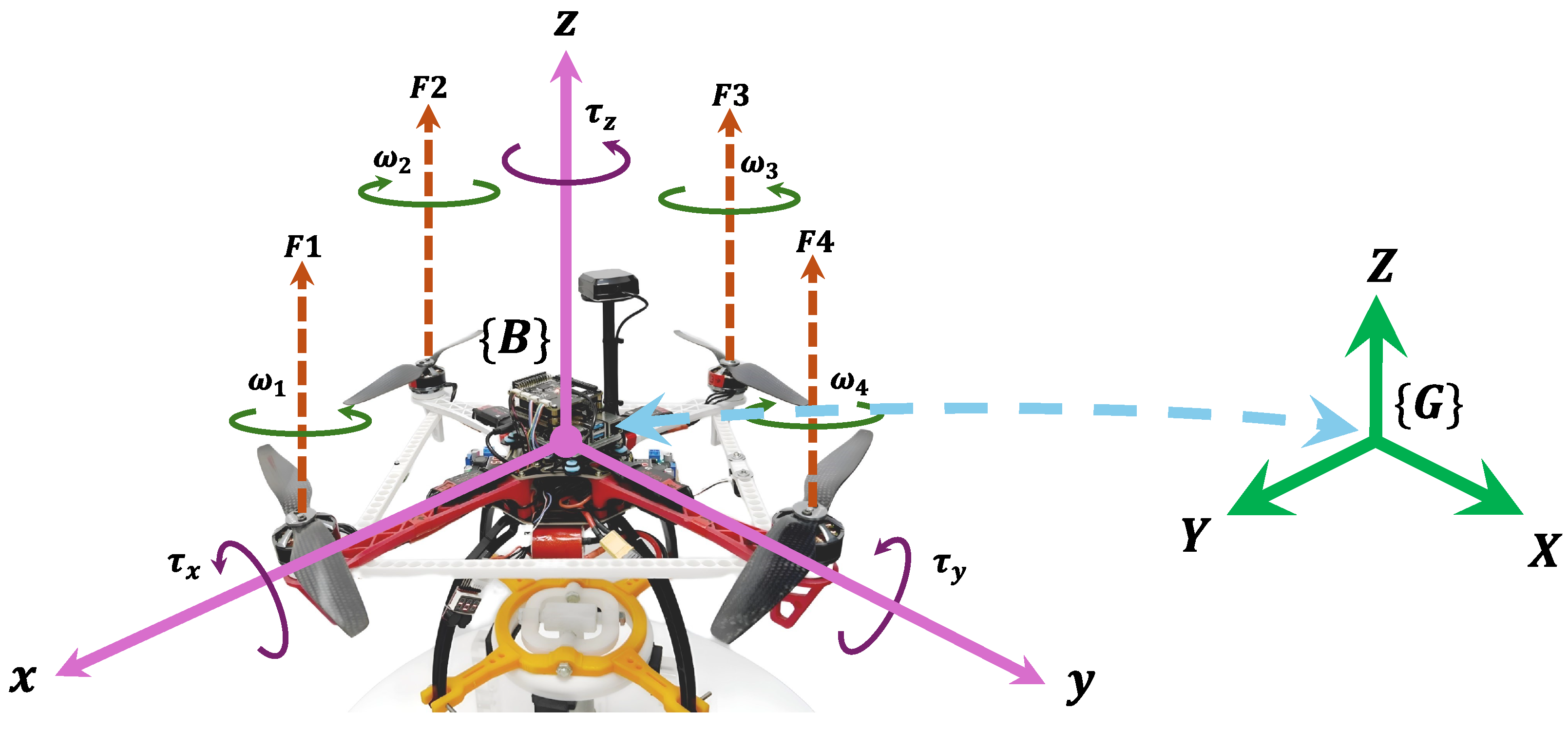
The quadrotor is modeled as a rigid, symmetric body with its center of gravity located at the origin of the body-fixed frame { B } , as shown in Figure 1. Its orientation relative to the inertial frame { G } is described by the Euler angles ϕ (roll), θ (pitch), and ψ (yaw). Ground effect and higher-order aerodynamic drag are neglected. The pitch angle θ determines the rotation of the quadrotor around the y-axis, the roll angle ϕ around the x-axis, and the yaw angle ψ around the z-axis. The model is linearized around hover conditions using the small-angle assumption.
Define the body angular velocity vector as ω b = [ p q r ] , where p, q, and r are the roll, pitch, and yaw rates about the body axes x, y, and z. The inertia matrix is I b = diag ( I x , I y , I z ) . The Euler-angle rates are related to the body rates by
ϕ ˙ θ ˙ ψ ˙ = W ( ϕ , θ ) ω b , W ( ϕ , θ ) = 1 sin ϕ tan θ cos ϕ tan θ 0 cos ϕ sin ϕ 0 sin ϕ sec θ cos ϕ sec θ .
The translational motion in the inertial frame { G } is [11,25,26,27]:
m X ¨ = F g + F T + F d ,
where m is the mass, X = [ x , y , z ] is the position vector, F g = [ 0 , 0 , m g ] represents the gravitational force, F T is the total thrust generated by the four rotors, and F d = D X ˙ denotes the linear aerodynamic drag, with D = diag ( K d x , K d y , K d z ) containing the drag coefficients, all expressed in the translational axes of { G } .
The total thrust f t produced by the rotors is given by [11,25,26,27]:
f t = K T i = 1 4 ω i 2 ,
where, K T is the thrust coefficient and ω i are the rotor angular speeds.
The rotational dynamics are obtained from Euler’s rigid-body equations. The control torques resulting from differential rotor thrust and drag are shown in Figure 1 [11,25,26,27]:
τ m = τ x τ y τ z = L K T ( ω 4 2 ω 2 2 ) L K T ( ω 3 2 ω 1 2 ) K d ( ω 2 2 + ω 4 2 ω 3 2 ω 1 2 ) ,
where, L is the arm length and K d is the drag torque coefficient. The gyroscopic torques induced by the spinning rotors are [11,25,26,27]:
τ g = I r θ ˙ Ω I r ϕ ˙ Ω 0 , Ω = ω 2 + ω 4 ω 3 ω 1 ,
where I r is the rotor inertia. The total angular motion is then described by [11,25,26,27]:
I b ω ˙ b + ω b × ( I b ω b ) = τ m + τ g + τ d .
For controller development, the dynamics of the controlled degrees of freedom are expressed in simplified form under the small-angle hover assumption. In this case, the kinematic relation η ˙ = W ( ϕ , θ ) ω b reduces to η ˙ ω b , implying ϕ ˙ p , θ ˙ q , and ψ ˙ r . The following attitude equations are derived using this approximation, while the translational model retains the exact trigonometric terms [13,25]:
ϕ ¨ = I y I z I x θ ˙ ψ ˙ + τ x I x + τ w x I x τ g y I x ,
θ ¨ = I z I x I y ϕ ˙ ψ ˙ + τ y I y + τ w y I y τ g x I y ,
ψ ¨ = I x I y I z ϕ ˙ θ ˙ + τ z I z + τ w z I z ,
x ¨ = 1 m f t cos ϕ sin θ cos ψ + sin ϕ sin ψ K d x x ˙ + f w x ,
y ¨ = 1 m f t cos ϕ sin θ sin ψ sin ϕ cos ψ K d y y ˙ + f w y ,
z ¨ = 1 m f t cos ϕ cos θ K d z z ˙ + f w z m g .
where, ϕ ˙ , θ ˙ , and ψ ˙ are the angular rates; τ x , τ y , and τ z are the control torques; and τ w x , τ w y , and τ w z are wind disturbance torques. The gyroscopic coupling terms are τ g x = J r ϕ ˙ Ω and τ g y = J r θ ˙ Ω . The altitude dynamics (11) include the total thrust f t , gravitational acceleration g, and any vertical force f w z . The disturbance terms f w x , f w y , and f w z act along the inertial axes. This study focuses on altitude z and attitude ( ϕ , θ , ψ ) regulation.

3. Model Reference Adaptive Controller

3.1. Overview

The Model Reference Adaptive Control (MRAC) scheme developed in this work regulates the altitude and attitude of the quadrotor. Each controlled degree of freedom, namely altitude z and the attitude angles ( ϕ , θ , ψ ) , is governed by an adaptive law designed to ensure that each subsystem follows a second-order reference model. The altitude controller adapts to uncertainties in mass, thrust, and gravitational disturbances, while the attitude controllers compensate for inertial asymmetries, gyroscopic effects, and aerodynamic coupling.

3.2. MRAC Framework

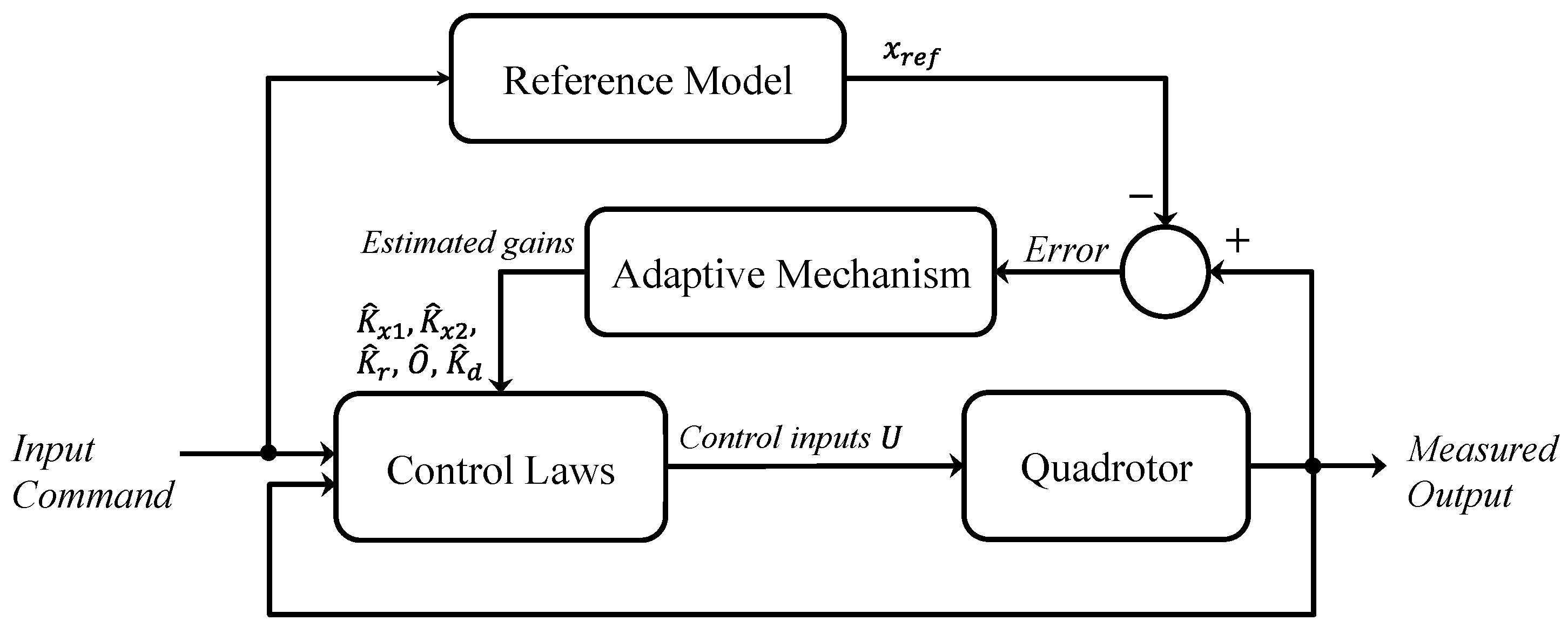
The MRAC framework is derived using Lyapunov stability theory [28], guaranteeing that the tracking error converges to zero in the presence of modeling uncertainties and external disturbances. By continuously adapting the control gains based on the real-time system response, the scheme maintains stability and accurate tracking for altitude and attitude channels. The overall MRAC structure is shown in Figure 2.
The derivation of the MRAC scheme presented in this section follows the formulations in [13,19,29,30], which form the basis for the simulation results described later. The quadrotor is modeled as a multi-input multi-output (MIMO) nonlinear system with matched uncertainties and additive disturbances. Its dynamics are expressed as:
x ˙ = A x + B Λ u + f ( x ) + B Λ d ,
where, x R n is the system state, u R m is the control input, A is an unknown constant state matrix, B is a known input matrix, Λ R m × m is an unknown diagonal matrix with positive diagonal entries, d R m is a constant disturbance, and f ( x ) represents a matched nonlinear uncertainty defined as:
f ( x ) = Θ Φ ( x ) ,
with Θ R N × m an unknown constant matrix and Φ ( x ) R N a known basis function (regressor) [29].

3.2.1. Reference Model

The reference model for the MRAC scheme is expressed in state-space form as:
x ˙ ref = A ref x ref + B ref r ( t )
where, A ref is a stable system matrix with all eigenvalues in the Left Half Plane, B ref is the reference input matrix, and r ( t ) is the command signal representing the desired trajectory.
Define the state error e x : = x x ref . For second-order systems, the tracking error typically includes both the state and its derivative and can be written as:
e = x x ref x ˙ x ˙ ref = e x e ˙ x .

3.2.2. Adaptive Control Laws

Assuming perfect knowledge of A and Λ , an ideal control input with a state-feedback and feedforward structure can be designed [30]:
u = K x x + K r r ( t ) Θ Φ ( x ) K d ,
where, K x and K r are the ideal feedback and feedforward gains, respectively, and K d compensates for matched disturbances. The ideal gains satisfy the matching conditions [30]:
A + B Λ K x = A ref , B Λ K r = B ref .
where K x and K r are the ideal constant gain matrices that achieve exact model following under the matching conditions. When the system parameters are unknown, the controller is implemented using adaptive parameter estimates:
u = K ^ x x + K ^ r r ( t ) Θ ^ Φ ( x ) K ^ d ,
where, K ^ x , K ^ r , Θ ^ , and K ^ d are the adaptive estimates. Substituting (18) into (12) and using (14) yields the tracking error dynamics:
e ˙ x = A ref e x + B Λ K ˜ x x + K ˜ r r ( t ) Θ ˜ Φ ( x ) K ˜ d ,
with the parameter estimation errors defined as:
K ˜ x = K ^ x K x , K ˜ r = K ^ r K r , Θ ˜ = Θ ^ Θ , K ˜ d = K ^ d K d .

3.3. Lyapunov-Based Stability and Adaptive Law Derivation

To ensure closed-loop stability, a Lyapunov function candidate is selected as [13,19]:
V = e P e + tr K ˜ x Γ x 1 K ˜ x + K ˜ r Γ r 1 K ˜ r + Θ ˜ Γ Θ 1 Θ ˜ + K ˜ d Γ d 1 K ˜ d Λ
where, P = P > 0 is chosen to satisfy the Lyapunov equation:
P A ref + A ref P = Q , Q = Q > 0 .
The matrix P determines the shape of the Lyapunov function, while Q specifies the convergence rate. The operator tr ( · ) denotes the trace. Differentiating V along the trajectories gives:
V ˙ = e ˙ P e + e P e ˙ + 2 tr K ˜ x Γ x 1 K ^ ˙ x + K ˜ r Γ r 1 K ^ ˙ r + Θ ˜ Γ Θ 1 Θ ^ ˙ + K ˜ d Γ d 1 K ^ ˙ d Λ .
Substituting (19) into (22) yields:
V ˙ = A ref e + B Λ ( K ˜ x x + K ˜ r r Θ ˜ Φ ( x ) K ˜ d ) P e + e P A ref e + B Λ ( K ˜ x x + K ˜ r r Θ ˜ Φ ( x ) K ˜ d ) + 2 tr K ˜ x Γ x 1 K ^ ˙ x + K ˜ r Γ r 1 K ^ ˙ r + Θ ˜ Γ Θ 1 Θ ^ ˙ + K ˜ d Γ d 1 K ^ ˙ d Λ .
Grouping terms and simplifying gives:
V ˙ = e Q e + 2 e P B Λ K ˜ x x + 2 e P B Λ K ˜ r r 2 e P B Λ Θ ˜ Φ ( x ) + 2 e P B Λ K ˜ d + 2 tr K ˜ x Γ x 1 K ^ ˙ x Λ + 2 tr K ˜ r Γ r 1 K ^ ˙ r Λ 2 tr Θ ˜ Γ Θ 1 Θ ^ ˙ Λ 2 tr K ˜ d Γ d 1 K ^ ˙ d Λ .
Applying the cyclic property of the trace operator, this can be written as:
V ˙ = e Q e + 2 tr K ˜ x [ Γ x 1 K ^ ˙ x + x e P B ] Λ + 2 tr K ˜ r [ Γ r 1 K ^ ˙ r + r e P B ] Λ + 2 tr Θ ˜ [ Γ Θ 1 Θ ^ ˙ Φ ( x ) e P B ] Λ + 2 tr K ˜ d [ Γ d 1 K ^ ˙ d e P B ] Λ .
To guarantee negative semi-definiteness of V ˙ , choose the adaptive update laws to cancel each trace term:
K ^ ˙ x = Γ x x e P B ,
K ^ ˙ r = Γ r r e P B ,
Θ ^ ˙ = Γ Θ Φ ( x ) e P B ,
K ^ ˙ d = Γ d e P B .
Substituting these into (25) yields:
V ˙ = e Q e 0 .
Thus, V ( t ) is nonincreasing, ensuring that the tracking error e ( t ) is globally stable and that all parameter estimation errors remain bounded. Differentiating (30) gives:
V ¨ = 2 e Q e ˙ .
Since e ˙ is bounded and Q is positive definite, it follows that V ¨ is bounded, which implies that V ˙ is uniformly continuous.

3.4. Decentralized MRAC Formulation for Quadcopter Model

For each controlled degree of freedom (attitude and altitude), the system is modeled as a second-order reference model. The reference dynamics are given by:
x ˙ ref x ¨ ref = A ref x ref x ˙ ref + B ref x desired ,
where the reference model matrices are defined as:
A ref = 0 1 ω n 2 2 ζ ω n , B ref = 0 ω n 2 .
Following [13], the nonlinear quadrotor dynamics can be expressed in a decentralized structure by defining the states:
x 1 = ϕ , x 5 = ψ , x 2 = ϕ ˙ , x 6 = ψ ˙ , x 3 = θ , x 7 = z , x 4 = θ ˙ , x 8 = z ˙ .
Accordingly, each attitude and altitude channel is represented as an individual second-order subsystem. These subsystems are expressed as:
a ˙ 1 = x 2 I y I z I x x 4 x 6 + τ x I x + τ w x I x ,
a ˙ 2 = x 4 I z I x I y x 2 x 6 + τ y I y + τ w y I y ,
a ˙ 3 = x 6 I x I y I z x 2 x 4 + τ z I z + τ w z I z ,
a ˙ 4 = x 8 1 m f t cos ( x 1 ) cos ( x 3 ) + f w z m g .
The state vectors for each channel are:
a 1 = x 1 x 2 = ϕ ϕ ˙ , a 2 = x 3 x 4 = θ θ ˙ , a 3 = x 5 x 6 = ψ ψ ˙ , a 4 = x 7 x 8 = z z ˙ .
The corresponding system matrices, nonlinear terms, and disturbance inputs for each subsystem are summarized as:
Roll subsystem ( i = 1 ):
A 1 = 0 1 0 0 , B 1 = 0 1 , Λ 1 = 1 I x , O 1 = I y I z , Φ 1 ( x ) = x 4 x 6 , u 1 = τ x , d 1 = τ w x .
Pitch subsystem ( i = 2 ):
A 2 = 0 1 0 0 , B 2 = 0 1 , Λ 2 = 1 I y , O 2 = I z I x , Φ 2 ( x ) = x 2 x 6 , u 2 = τ y , d 2 = τ w y .
Yaw subsystem ( i = 3 ):
A 3 = 0 1 0 0 , B 3 = 0 1 , Λ 3 = 1 I z , O 3 = I x I y , Φ 3 ( x ) = x 2 x 4 , u 3 = τ z , d 3 = τ w z .
Altitude subsystem ( i = 4 ):
A 4 = 0 1 0 0 , B 4 = 0 1 , Λ 4 = 1 m cos ( x 1 ) cos ( x 3 ) , u 4 = f t , d 4 = m g + f w z .

3.5. Attitude and Altitude Control Law

Each attitude axis is modeled as a second-order subsystem and controlled using the MRAC framework described in (18). To separate matched nonlinear uncertainties from the general adaptive term Θ ^ , the notation O ^ is introduced. The control inputs for roll, pitch, and yaw are expressed as:
u 2 = K ^ ϕ 1 ϕ + K ^ ϕ 2 ϕ ˙ + K ^ ϕ r ϕ desired O ^ ϕ ( θ ˙ ψ ˙ ) K ^ ϕ d ,
u 3 = K ^ θ 1 θ + K ^ θ 2 θ ˙ + K ^ θ r θ desired O ^ θ ( ϕ ˙ ψ ˙ ) K ^ θ d ,
u 4 = K ^ ψ 1 ψ + K ^ ψ 2 ψ ˙ + K ^ ψ r ψ desired O ^ ψ ( ϕ ˙ θ ˙ ) K ^ ψ d ,
where, K ^ x 1 , K ^ x 2 , and K ^ x r ( x { ϕ , θ , ψ } ) are the adaptive feedback and feedforward gains for angle, angular rate, and reference command, respectively. The terms O ^ x estimate cross-axis coupling effects, while K ^ x d compensates for external disturbances such as wind forces and gyroscopic torques. The altitude control law follows the same structure:
u 1 = K ^ z 1 z + K ^ z 2 z ˙ + K ^ z r z desired K ^ z d ,
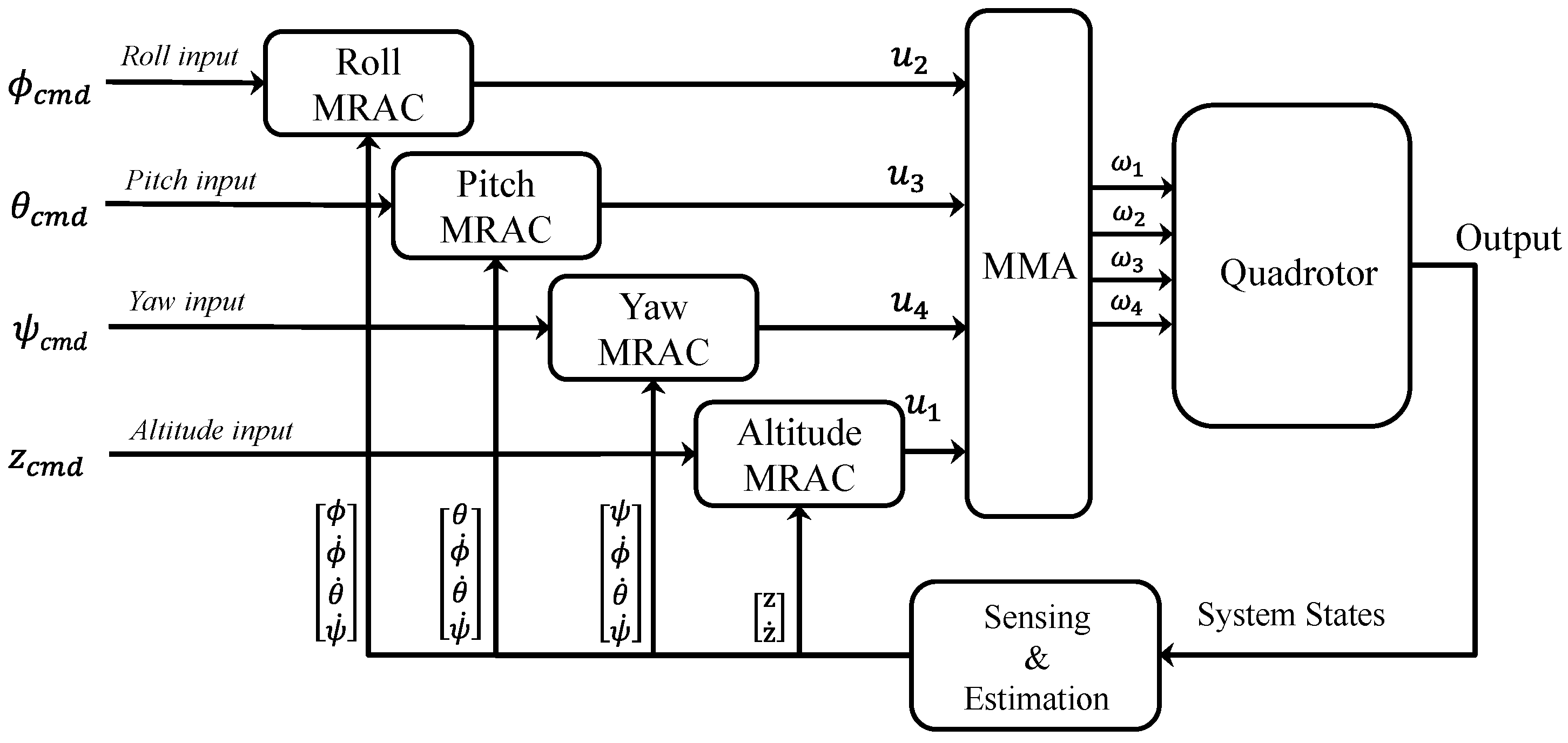
where, K ^ z 1 , K ^ z 2 , and K ^ z r are the adaptive gains for altitude, vertical velocity, and reference command, respectively. The term K ^ z d compensates for vertical disturbances, including gravity and wind. Figure 3 shows the overall MRAC-based control architecture for the quadrotor. Four independent MRAC controllers generate axis-specific control signals u 1 , u 2 , u 3 , u 4 based on the commanded and measured states. These control signals are processed by the Mixer and Motor Allocation (MMA) module, which converts them into motor angular velocities ω 1 , ω 2 , ω 3 , ω 4 . The quadrotor dynamics produce the motion response, and the resulting states are measured and fed back through the sensing and estimation block to close the control loop.
Although each MRAC controller is designed for a single degree of freedom, cross-axis coupling effects that arise during aggressive maneuvers or strong disturbances are compensated through the adaptive terms O ^ x in the control laws. These terms estimate and counteract dynamic interactions such as gyroscopic and inertial coupling (e.g., roll–yaw or pitch–yaw effects) using the measured angular rates. By continuously adapting O ^ x through the update laws described in Section 3.2.2 and Section 3.3, the MRAC framework preserves stability and accurate tracking under dynamic coupling while maintaining a decentralized structure, allowing each axis to reject disturbances independently in real time.

3.6. Adaptive Mechanism

Using the Lyapunov-based formulation, the adaptive update laws adjust the controller gains for each channel to ensure that the tracking error converges to zero. For each attitude and altitude subsystem, let P denote a positive-definite solution to the Lyapunov equation in (21), and let B represent the input matrix as defined in the state-space form in Section 3.4. The update laws for the individual subsystems are as follows:
(a)
Roll subsystem: The tracking error is:
e ϕ = ϕ ϕ ref ϕ ˙ ϕ ˙ ref .
The adaptive feedback gain K ^ ϕ , feedforward gain K ^ ϕ r , uncertainty estimation O ^ ϕ , and disturbance compensation K ^ ϕ d are updated as:
K ^ ˙ ϕ = γ ϕ ϕ ϕ ˙ e ϕ P B ,
K ^ ˙ ϕ r = γ ϕ r ϕ desired e ϕ P B ,
O ^ ˙ ϕ = γ ϕ O ( θ ˙ ψ ˙ ) e ϕ P B ,
K ^ ˙ ϕ d = γ ϕ d e ϕ P B .
(b)
Pitch subsystem: The tracking error is:
e θ = θ θ ref θ ˙ θ ˙ ref .
The adaptive feedback gain K ^ θ , feedforward gain K ^ θ r , uncertainty estimation O ^ θ , and disturbance compensation K ^ θ d are updated as:
K ^ ˙ θ = γ θ θ θ ˙ e θ P B ,
K ^ ˙ θ r = γ θ r θ desired e θ P B ,
O ^ ˙ θ = γ θ O ( ϕ ˙ ψ ˙ ) e θ P B ,
K ^ ˙ θ d = γ θ d e θ P B .
(c)
Yaw subsystem: The tracking error is:
e ψ = ψ ψ ref ψ ˙ ψ ˙ ref .
The adaptive feedback, feedforward, and disturbance compensation terms, along with the uncertainty estimate O ^ ψ for cross-coupling, are updated as:
K ^ ˙ ψ = γ ψ ψ ψ ˙ e ψ P B ,
K ^ ˙ ψ r = γ ψ r ψ desired e ψ P B ,
O ^ ˙ ψ = γ ψ O ( ϕ ˙ θ ˙ ) e ψ P B ,
K ^ ˙ ψ d = γ ψ d e ψ P B .
(d)
Altitude subsystem: The tracking error is:
e z = z z ref z ˙ z ˙ ref .
The adaptive feedback gain K ^ z , reference tracking gain K ^ z r , and disturbance term K ^ z d are updated as:
K ^ ˙ z = γ z z z ˙ e z P B ,
K ^ ˙ z r = γ z r z desired e z P B ,
K ^ ˙ z d = γ z d e z P B .
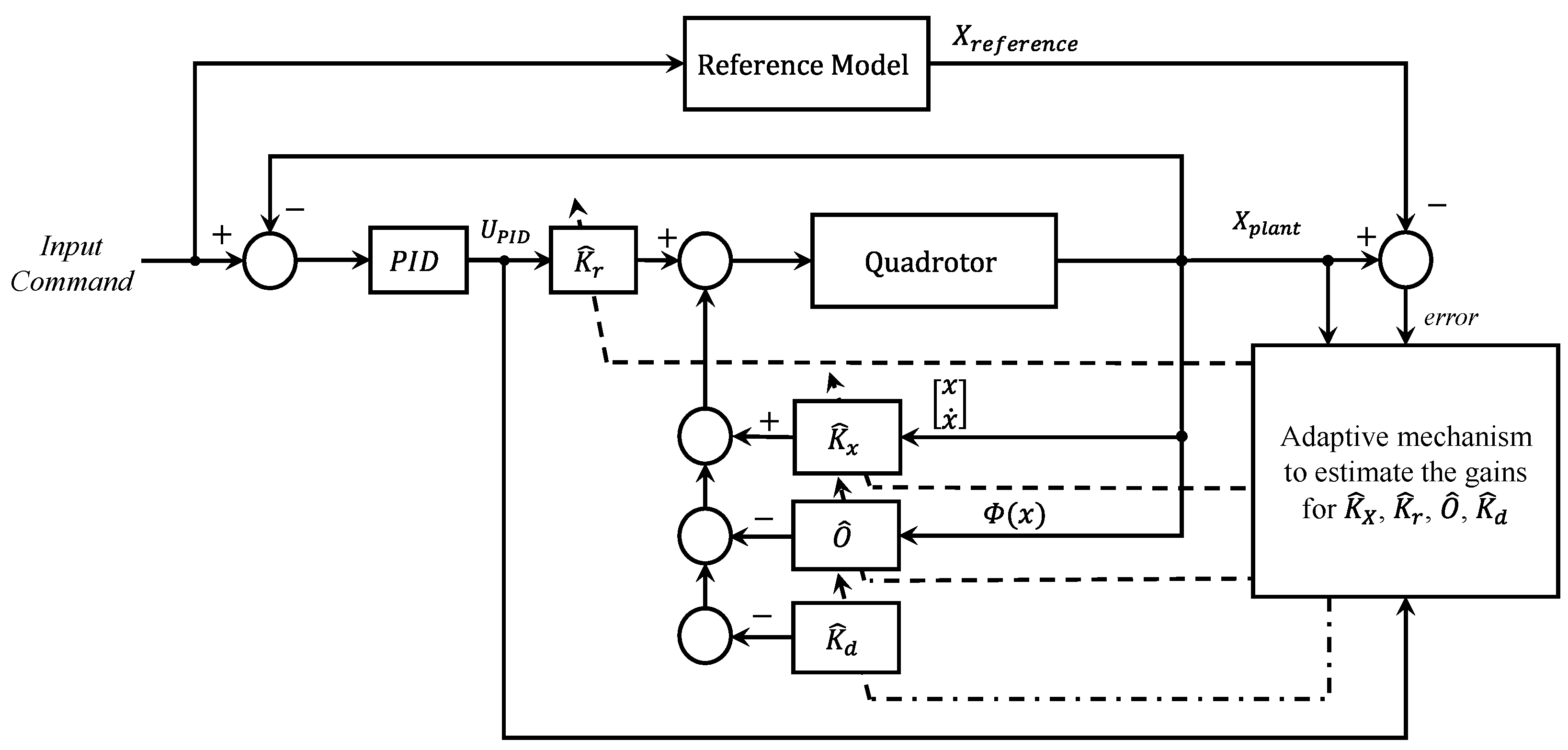
In all subsystems, γ represent the learning rates for each adaptive gain. These update laws guarantee convergence of the tracking error while keeping all parameter estimates bounded. Figure 4 shows the generalized MRAC controller block diagram for the quadrotor.

4. Cascaded Hybrid MRAC–LQR with Integral Action Scheme

4.1. Linear Quadratic Regulator with Integral Action

Integrating an optimal Linear Quadratic Regulator (LQR) with MRAC can improve tracking performance, as demonstrated in several studies [22,23,24]. Before presenting the combined MRAC–LQR scheme, the LQR design with integral action is briefly reviewed.
The LQR is an optimal control approach that, given a linearized state-space model, computes a feedback control law to drive the system states to zero while minimizing a quadratic performance index [24]. For the nominal linear time-invariant system:
x ˙ = A x + B u , y = C x ,
the infinite-horizon quadratic cost functional to be minimized is [24]:
J = 0 x Q x + u R u d t ,
where the symmetric positive semi-definite matrix Q and positive definite matrix R penalize the state deviation and control effort, respectively. To eliminate steady-state error when tracking a reference r ( t ) , integral action is incorporated [24]. The integrator state is defined as:
i ˙ = r ( t ) y = r ( t ) C x .
Augmenting the original state with i gives [24]:
x ˙ i ˙ = A 0 C 0 x i + B 0 u + 0 I m r ,
where I m R m × m is the identity matrix corresponding to the dimension of the command input. The state-feedback control law is expressed as:
u = K p x K i i ,
where K p and K i are the proportional and integral gain matrices, respectively, obtained by solving the LQR problem for the augmented system in (65). The matrix K p has as many columns as the number of original states n, and K i matches the dimension of the integrator states m. The combined LQR gain is given by:
K LQR = K p K i = R 1 B P ,
where the symmetric positive-definite matrix P solves the algebraic Riccati equation [31]:
A P + P A + Q P B R 1 B P = 0 .

4.2. LQR Controller for the Linearized Quadrotor Dynamics

To compute the gains for the LQR controller, a linearized state-space model of the quadrotor is used. Following [32], the small-angle approximation is adopted, assuming that external forces are negligible during hover. This simplification implies that translational and rotational velocities are small, and the equilibrium state vector and control inputs are zero, except for u 1 , which represents thrust and must balance gravity as u 1 = m g . Higher-order nonlinear terms are neglected to simplify the control design. Under these assumptions, the linearized equations of motion are:
ϕ ¨ = u 2 I x , θ ¨ = u 3 I y , ψ ¨ = u 4 I z , z ¨ = u 1 m g m ,
where u 1 = f t , u 2 = τ x , u 3 = τ y , and u 4 = τ z  [31]. To eliminate steady-state error, an integrator is added for each channel by integrating the tracking error [31]:
i ϕ = ( ϕ cmd ϕ ) d t , i θ = ( θ cmd θ ) d t , i ψ = ( ψ cmd ψ ) d t , i z = ( z cmd z ) d t .
Each channel is represented as an augmented three-state system, where the augmented state is ξ = [ x ; x ˙ ; i ] . The state-space models for each channel are:
(a)
Roll channel:
ϕ ˙ ϕ ¨ i ˙ ϕ ξ ˙ ϕ = 0 1 0 0 0 0 1 0 0 A aug , ϕ ϕ ϕ ˙ i ϕ ξ ϕ + 0 1 / I x 0 B aug , ϕ u 2 + 0 0 1 B cmd , ϕ ϕ cmd .
(b)
Pitch channel:
θ ˙ θ ¨ i ˙ θ ξ ˙ θ = 0 1 0 0 0 0 1 0 0 A aug , θ θ θ ˙ i θ ξ θ + 0 1 / I y 0 B aug , θ u 3 + 0 0 1 B cmd , θ θ cmd .
(c)
Yaw channel:
ψ ˙ ψ ¨ i ˙ ψ ξ ˙ ψ = 0 1 0 0 0 0 1 0 0 A aug , ψ ψ ψ ˙ i ψ ξ ψ + 0 1 / I z 0 B aug , ψ u 4 + 0 0 1 B cmd , ψ ψ cmd .
(d)
Altitude channel:
z ˙ z ¨ i ˙ z ξ ˙ z = 0 1 0 0 0 0 1 0 0 A aug , z z z ˙ i z ξ z + 0 1 / m 0 B aug , z ( u 1 m g ) + 0 0 1 B cmd , z z cmd .
Each augmented model follows the general state structure ξ = [ x ; x ˙ ; i ] , where x is the physical variable, x ˙ is its rate, and i is the integral of the tracking error. The optimal feedback gains for each channel are computed using MATLAB’s built-in LQR solver [33]:
K LQR = lqr ( A aug , B aug , Q , R ) ,
The weighting matrix Q = diag ( Q pos , Q vel , Q int ) penalizes position deviation, velocity, and integral error. The scalar R > 0 limits control effort: a larger R yields smoother but slower responses, whereas a smaller R delivers faster control at the expense of higher actuator demand and potential overshoot.

4.3. Updated Control Law for Hybrid MRAC–LQR

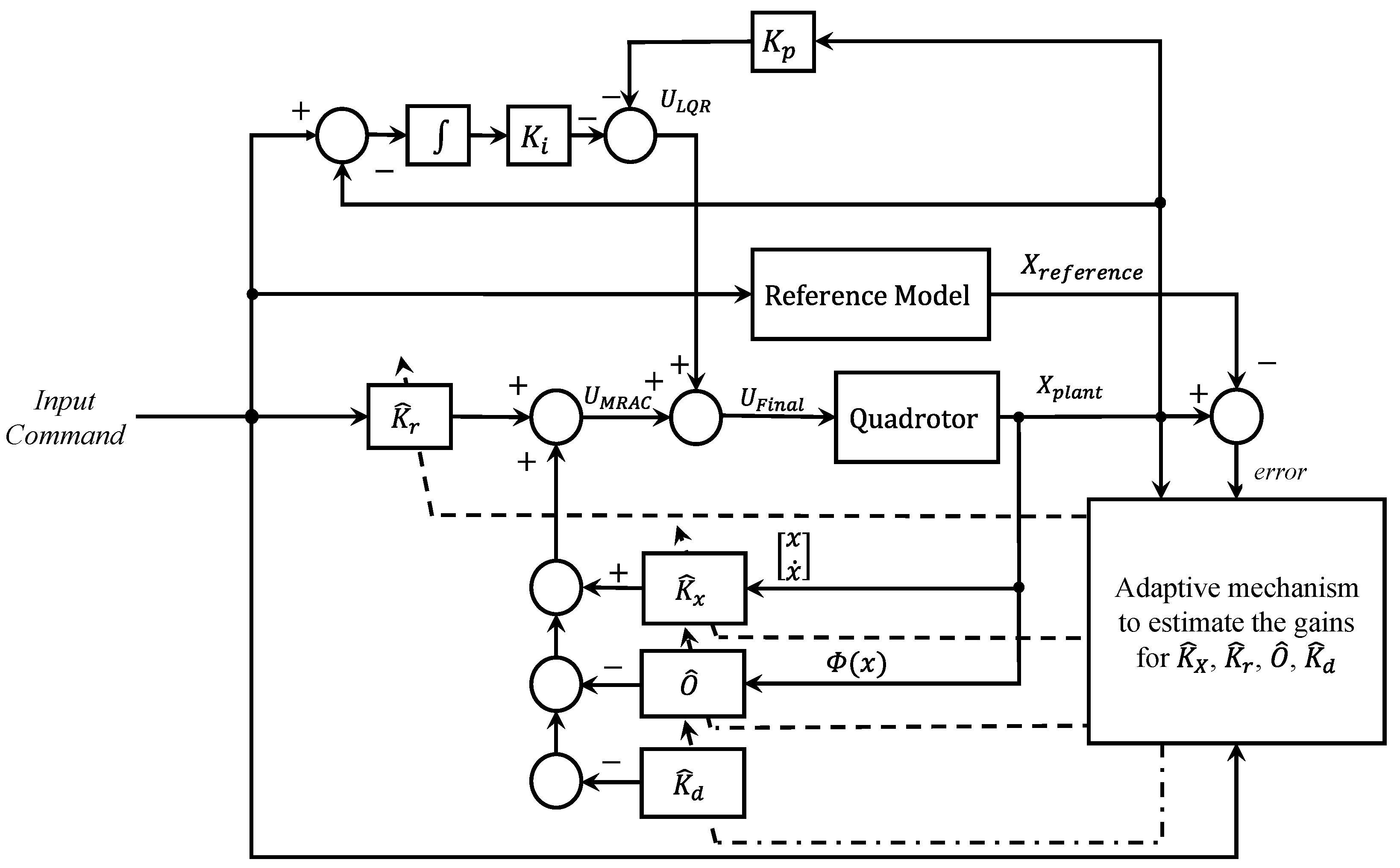
Figure 5 illustrates how the LQR output, U LQR , is incorporated as a feedforward command within the MRAC scheme, following the same structure used in the MRAC–PID configuration. The tracking error is processed by the LQR controller, and its output replaces the standard reference input in the MRAC control law. In this configuration, U LQR is applied both as the control input to the system and as the signal driving the adaptive update of the MRAC parameters. The LQR control outputs for each channel are:
U LQR ϕ = K p ϕ ϕ ϕ ˙ K ϕ i ϕ cmd ϕ d t ,
U LQR θ = K p θ θ θ ˙ K θ i θ cmd θ d t ,
U LQR ψ = K p ψ ψ ψ ˙ K ψ i ψ cmd ψ d t ,
U LQR z = K p z z z ˙ K z i z cmd z d t .
The MRAC control laws for the four channels are then updated as:
u 2 = K ^ ϕ 1 ϕ + K ^ ϕ 2 ϕ ˙ + K ^ ϕ r U LQR ϕ O ^ ϕ ( θ ˙ ψ ˙ ) K ^ ϕ d ,
u 3 = K ^ θ 1 θ + K ^ θ 2 θ ˙ + K ^ θ r U LQR θ O ^ θ ( ϕ ˙ ψ ˙ ) K ^ θ d ,
u 4 = K ^ ψ 1 ψ + K ^ ψ 2 ψ ˙ + K ^ ψ r U LQR ψ O ^ ψ ( ϕ ˙ θ ˙ ) K ^ ψ d ,
u 1 = K ^ z 1 z + K ^ z 2 z ˙ + K ^ z r U LQR z K ^ z d .
As a result of this modification, the adaptive update laws for the feedforward gains are expressed as:
K ^ ˙ ϕ r = γ ϕ r U LQR ϕ e ϕ P B ,
K ^ ˙ θ r = γ θ r U LQR θ e θ P B ,
K ^ ˙ ψ r = γ ψ r U LQR ψ e ψ P B ,
K ^ ˙ z r = γ z r U LQR z e z P B .

4.4. Hybrid MRAC−PID Controller Scheme

As shown in prior studies [19,20,21], incorporating a PID controller within the inner loop of an MRAC framework and embedding it into the adaptive mechanism can improve performance. Figure 6 illustrates the integration of the PID controller into the MRAC scheme. In this configuration, the error between the commanded input and the quadrotor output is first processed by the PID controller. The PID output, U PID , replaces the reference trajectory in the MRAC adaptation mechanism. The control inputs for roll, pitch, yaw, and altitude are then expressed as:
u 2 = K ^ ϕ 1 ϕ + K ^ ϕ 2 ϕ ˙ + K ^ ϕ r U PID ϕ O ^ ϕ ( θ ˙ ψ ˙ ) K ^ ϕ d ,
u 3 = K ^ θ 1 θ + K ^ θ 2 θ ˙ + K ^ θ r U PID θ O ^ θ ( ϕ ˙ ψ ˙ ) K ^ θ d ,
u 4 = K ^ ψ 1 ψ + K ^ ψ 2 ψ ˙ + K ^ ψ r U PID ψ O ^ ψ ( ϕ ˙ θ ˙ ) K ^ ψ d ,
u 1 = K ^ z 1 z + K ^ z 2 z ˙ + K ^ z r U PID z K ^ z d .
The feedforward adaptation laws are modified by replacing the desired reference input with the PID-controlled signal U PID :
K ^ ˙ ϕ r = γ ϕ r U PID ϕ e ϕ P B ,
K ^ ˙ θ r = γ θ r U PID θ e θ P B ,
K ^ ˙ ψ r = γ ψ r U PID ψ e ψ P B ,
K ^ ˙ z r = γ z r U PID z e z P B .
The remaining adaptive update laws for K ^ ˙ x , O ^ ˙ x , and K ^ ˙ x d are identical to those in the standard MRAC formulation. This allows the PID correction to influence both the control action and the adaptive mechanism, improving transient response while retaining the robustness characteristics of MRAC.

5. Simulation Framework

The simulation was carried out in MATLAB to evaluate the performance of the MRAC-based controllers for the altitude and attitude channels, following the decentralized structure described in Section 3.4. Each control loop was initialized with the identified quadrotor parameters and updated in real time according to the adaptive laws. All controllers were executed with a fixed discrete sampling period of T s = 0.005 s (200 Hz). At each sample t k , the reference model was numerically integrated over the interval [ t k , t k + 1 ] , while the adaptive and control laws were updated using the measured states at t k . The same T s was used in the standalone MRAC, MRAC–PID, and cascaded MRAC–LQR to ensure consistent performance comparison. The reference trajectories were generated and passed through the respective reference models to produce the desired model states. These were then used to compute the adaptive gains and control inputs for the three MRAC configurations. The full nonlinear quadrotor dynamics were integrated at each time step, and the state and control histories were recorded for post-processing and performance evaluation. The overall simulation procedure for the MRAC-based quadrotor control framework is summarized in Algorithm 1.
Algorithm 1 Simulation framework for MRAC-based quadrotor control
Require: Quadrotor parameters ( I x , I y , I z , m , g , b , d , l ) , adaptive learning rates Γ , reference model matrices ( A ref , B ref ) , simulation duration t final , and sampling period T s .
Ensure: Time histories of reference trajectories, adaptive gains, control inputs, system states, and tracking errors.
1:
Initialize quadrotor model and MRAC parameters.
2:
Set initial system state x ( 0 ) , reference model state x ref ( 0 ) , and adaptive gains K ^ ( 0 ) .
3:
Specify input command mode and compute initial desired reference.
4:
for each time step n = 1 : N 1  do
5:
    Update desired commands ( ϕ cmd , θ cmd , ψ cmd , z cmd ) .
6:
    Integrate reference model dynamics x ref over [ t n , t n + 1 ] using ode45.
7:
    Apply scheduled wind disturbances ( f w x , f w y , f w z ) and mass variation m ( t ) .
8:
    Update adaptive parameters K ^ x , K ^ r , O ^ x , K ^ d using the adaptive laws.
9:
    Compute control inputs u = ( u ϕ , u θ , u ψ , u z ) .
10:
   Map control inputs to rotor speeds ω = ( ω 1 , ω 2 , ω 3 , ω 4 ) .
11:
   Integrate plant dynamics x over [ t n , t n + 1 ] under control inputs and disturbances.
12:
   Store x , x ref , K ^ , u , ω for post-processing.
13:
end for
14:
Compute MSE for roll, pitch, yaw, and altitude tracking.

5.1. Parameter Identification for Simulation

For accurate simulation of quadrotor dynamics, the physical parameters were identified using standard methods validated in prior works [34,35]. The total mass of the quadrotor was measured directly, and the bifilar pendulum method was used to estimate the rotational inertias about the roll, pitch, and yaw axes. The moments of inertia were computed using the relation:
I x , y , z = w T osc 2 D 2 16 π 2 L
where w = m g is the total weight, T osc is the oscillation period, D is the rope spacing, and L is the suspension length. The quadrotor model parameters used in the simulations are summarized in Table 1.

5.2. Controller Gains and Learning Rates Optimization

The MRAC framework includes fifteen adaptive learning-rate constants γ , which govern how fast the adaptive gains respond to the tracking error. These learning rates must be carefully tuned to ensure both rapid adaptation and stable performance across the altitude and attitude axes. Before tuning, a lower bound for the learning rates γ was obtained from Lyapunov stability, ensuring the Lyapunov function derivative remains negative definite and the error dynamics remain stable.
The Nelder–Mead direct search algorithm [36] was used to minimize the MSE across the four control axes. The Nelder–Mead method is a derivative-free, simplex-based algorithm that converges reliably for smooth, low-dimensional problems such as the fifteen-parameter learning-rate tuning performed here [36]. Although it does not guarantee a global optimum, multiple random initializations were tested to confirm that the solutions were consistent and provided stable closed-loop behavior across all simulation scenarios. Alternative global optimization methods, including metaheuristic algorithms, were considered. However, these approaches require a significantly larger number of function evaluations, each involving full nonlinear dynamic simulations, which leads to prohibitive computational costs when tuning the MRAC, MRAC–PID, and MRAC–LQR controllers. Since the optimized parameters exhibited consistent performance under command changes, wind disturbances, and mass variation, Nelder–Mead was selected as the most computationally efficient and reliable approach for this study. The same optimized learning-rate constants γ were applied uniformly to all three controllers (MRAC, MRAC–PID, and MRAC–LQR) to ensure a fair basis for comparison. The final learning-rate values used in the simulations are summarized in Table 2.
Similarly, the twelve PID gains used in the hybrid MRAC–PID controller were optimized using the Nelder–Mead algorithm. With the MRAC learning rates fixed at their values from Table 2, the PID parameters were tuned to minimize the same MSE-based cost function. The final optimized gains used in the simulations are presented in Table 3.
It is important to note that the resulting gains correspond to a local optimum. The performance of the Nelder–Mead algorithm, as implemented in MATLAB’s fminsearch function, is inherently sensitive to the initial parameter values and stopping conditions. These stopping conditions include TolX, which specifies the minimum change in parameter values between iterations, and TolFun, which specifies the minimum change in the objective function value. The optimization also terminates when the maximum number of iterations is reached. Despite these limitations, the obtained gains yielded consistent and robust performance across all tested scenarios and were therefore retained for subsequent analysis.
The optimized γ values and PID gains reported in Table 2 and Table 3 were selected solely by minimizing the overall MSE across all test cases. No rotor-speed or thrust constraints were imposed during the optimization. The resulting gains provide fast adaptation and robust performance under the modeled disturbances and mass variations.

5.3. LQR Optimal Gains

To tune the MRAC–LQR controller, optimal state-feedback gains were computed for both the attitude and altitude channels using the linearized quadrotor model described in Section 4.2. The weighting matrices Q and R were selected to shape the closed-loop response, with larger penalties assigned to the integral error to improve steady-state performance.

5.3.1. Attitude Channels

Q int = 1000 , Q pos = 100 , Q vel = 1 , R = 1
These weights emphasize integral action to eliminate steady-state error while applying moderate penalties on position and velocity deviations to ensure stability without excessive control effort.

5.3.2. Altitude Channel

For the altitude channel, larger penalties were required due to the constant influence of gravity. This ensures minimal deviation from the altitude setpoint even under persistent disturbances.
Q int , z = 10 000 , Q pos , z = 5 000 , Q vel , z = 100 , R z = 1
The control effort penalty R was kept at 1 for both the attitude and altitude channels to allow moderate actuation without overly aggressive responses. Placing these weights along the diagonal of Q allowed MATLAB’s solver to compute the optimal gains by solving the Riccati equation.

5.4. Command Steps, Wind Disturbances, and Parameter Changes

The simulation applies the piecewise-constant command profile summarized in Table 4. Every 20 s, the reference commands are updated: each attitude angle (roll, pitch, and yaw) is increased by 10 , while the altitude is first raised by 0.5 m and then doubled at the subsequent step.
A wind disturbance is introduced at t = 60 s , with the magnitude varied twice to evaluate disturbance rejection, as summarized in Table 5. Identical forces act along the x, y, and z body axes, and the disturbance levels are intentionally set high to test each controller’s robustness.
At t = 100 s , the quadrotor mass is reduced by 0.5 kg (from 2.29 kg to 1.79 kg) to evaluate the controllers’ response to sudden parameter variation.
Aerodynamic coupling and mass variation are explicitly modeled in the simulation to assess robustness. Cross-axis aerodynamic effects, including inertial and gyroscopic coupling, are incorporated using the nonlinear interaction terms in the dynamic model and are compensated by the adaptive O ^ x terms in the control laws. These effects are most pronounced during the command steps and wind disturbances, representing conditions typical of aggressive maneuvers. Mass variation is introduced as a sudden change at t = 100 s , simulating events such as payload release. Wind disturbances are modeled as piecewise-constant forces along all three axes (Table 5), requiring the adaptive terms to readjust as conditions evolve. These modeling choices ensure that the simulation represents realistic flight conditions, including cross-axis loads, payload changes, and gust disturbances. The adaptive update laws are tested under these conditions to confirm their ability to maintain stability and accurate tracking as the system dynamics vary in real time.

6. Results

This section demonstrates a comparative analysis of the three different types of MRAC controllers: standalone MRAC, MRAC augmented with PID, and MRAC augmented with LQR.

6.1. Altitude Responses

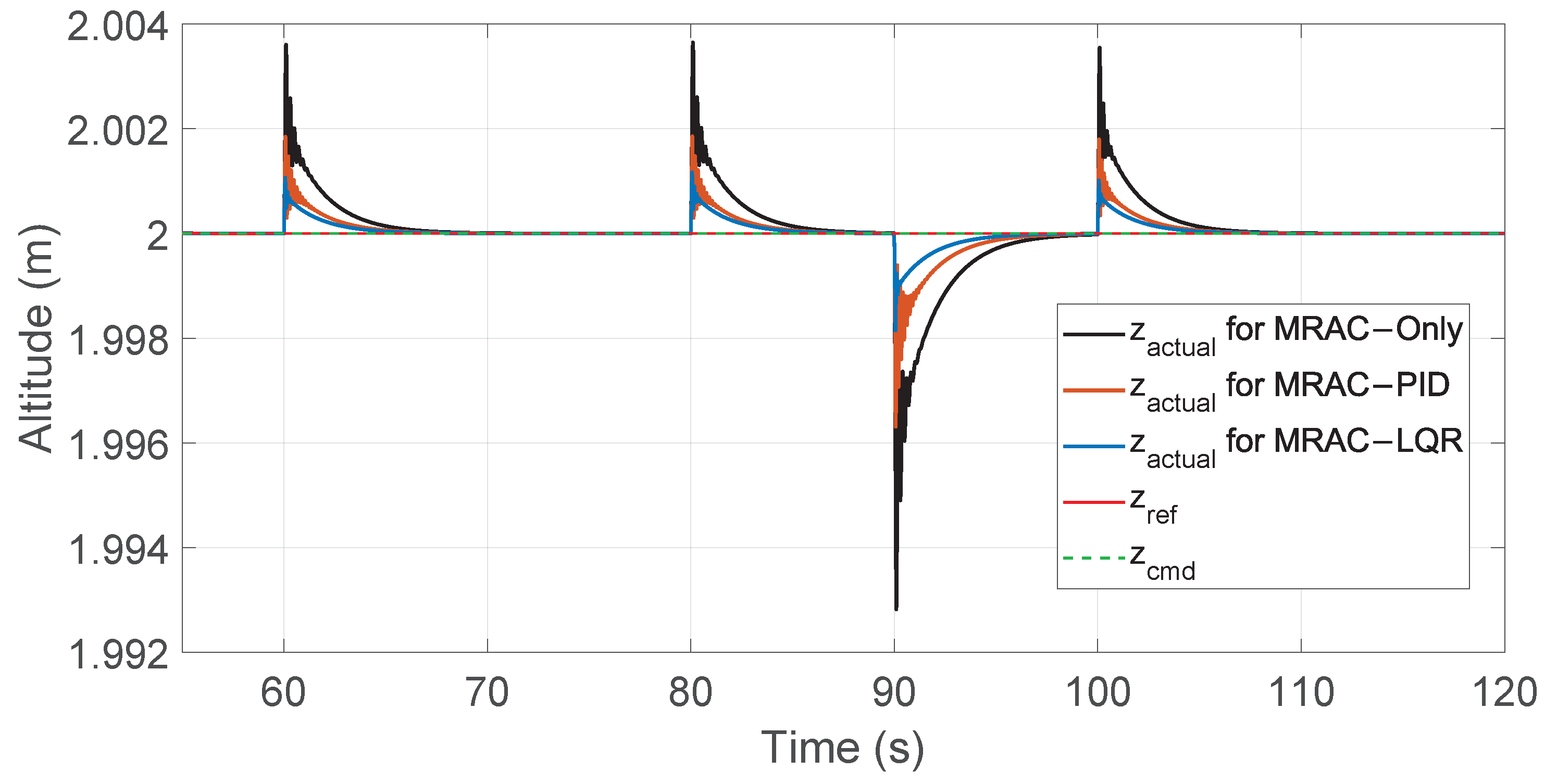
Figure 7 shows that all controllers track the output of the reference model as required. The key difference appears in the zoomed section between 55 s and 120 s (Figure 8), where the differences between the reactions of each controller are demonstrated. It can be observed that the standalone MRAC controller exhibited the highest spikes when disturbances were applied to the system, followed by the MRAC–PID, and finally the MRAC–LQR.
Referring to the altitude tracking in Figure 7, at the start of the simulation, MRAC–LQR had the lowest tracking error, whereas the other methods experienced significant spikes in error. However, all three methods converged to zero around 9 s. Furthermore, when the step command was modified at 20 s and 40 s, the MRAC–PID had the fastest response to the command changes, adjusting the error quicker than the other two controllers. However, it showed substantial oscillations compared to the MRAC and MRAC–LQR results.
Moreover, in the zoomed section during disturbances and mass changes, the MRAC–LQR exhibited the smallest variations among the three controllers, followed by MRAC–PID, and lastly, the standalone MRAC. It is important to note that all three controllers showed their highest tracking errors during step changes. Furthermore, among all disturbance scenarios, the largest error occurred when the 10 N wind force was fully removed, because the adapted gains had to be readjusted to the appropriate values for undisturbed conditions.
A full comparison between the error peaks of the three controllers and the MSE values is presented in Section 7. Figure 9 shows the corresponding altitude tracking errors for standalone MRAC, MRAC–PID, and MRAC–LQR.

6.2. Attitude Response

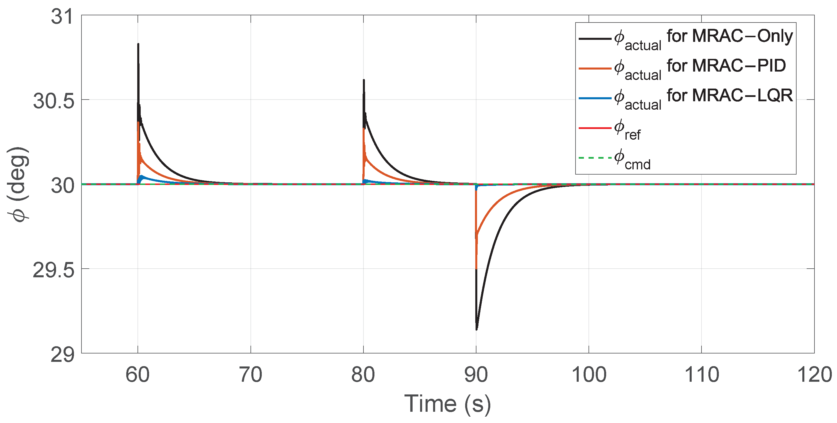
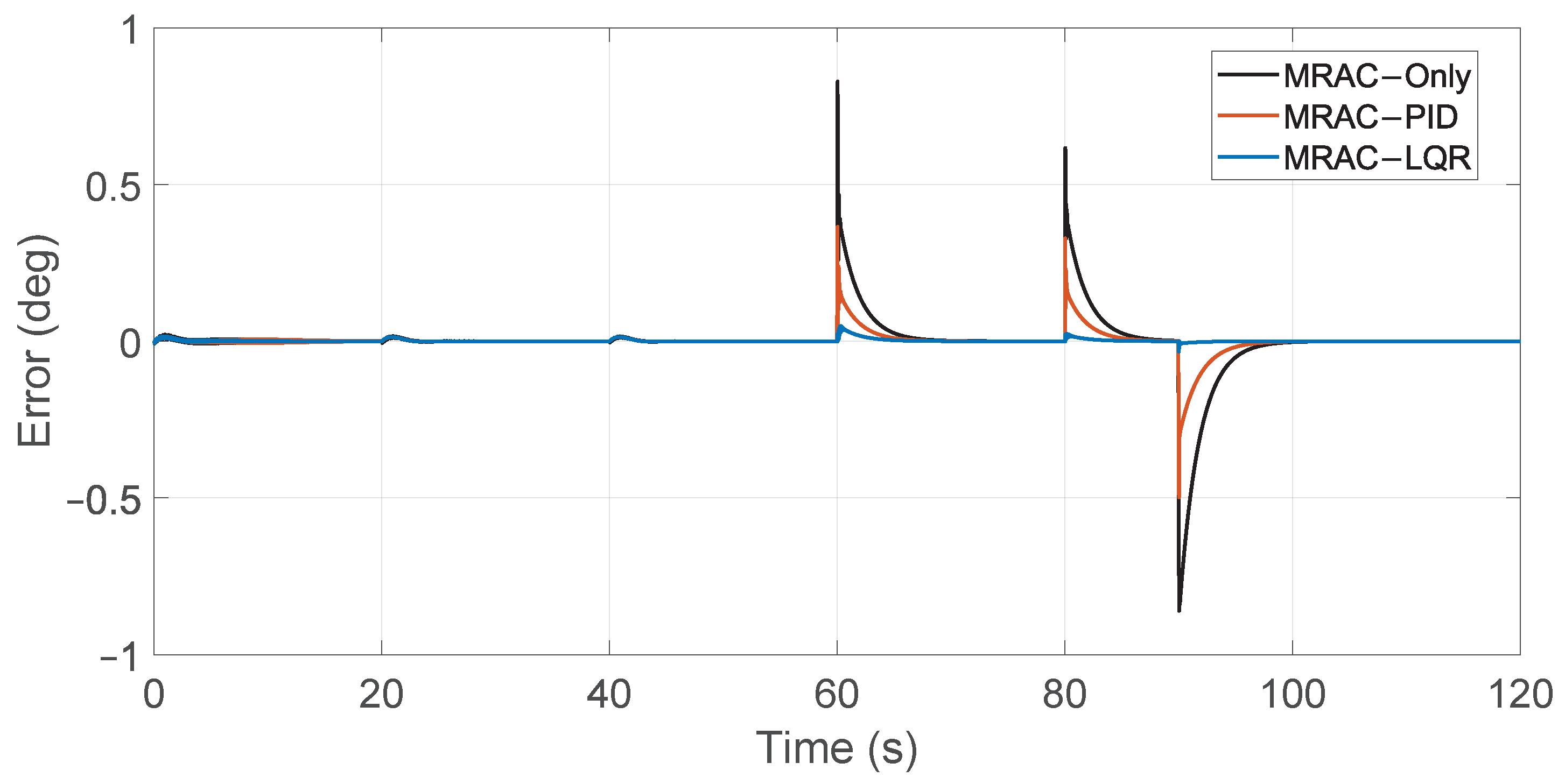
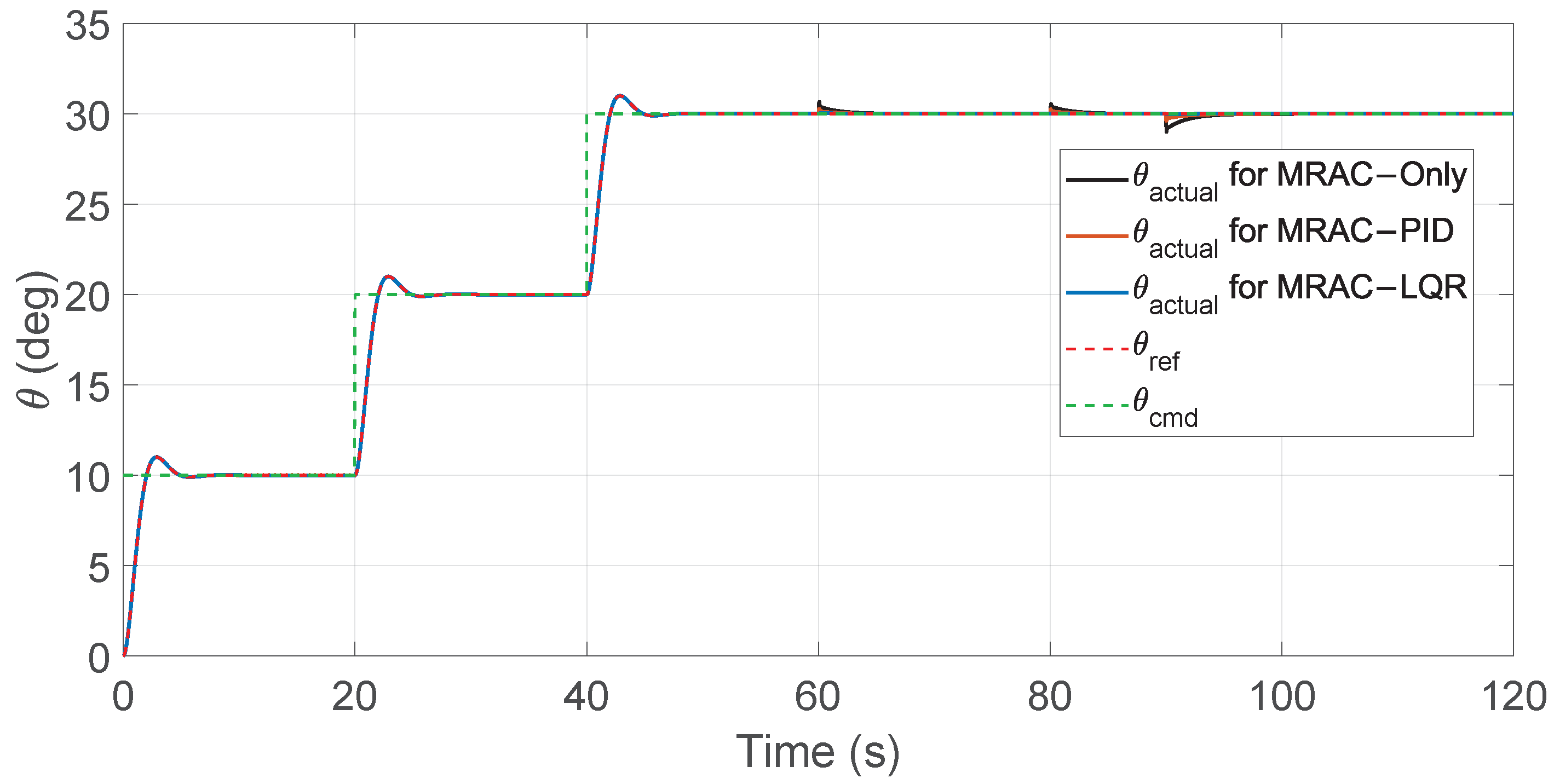
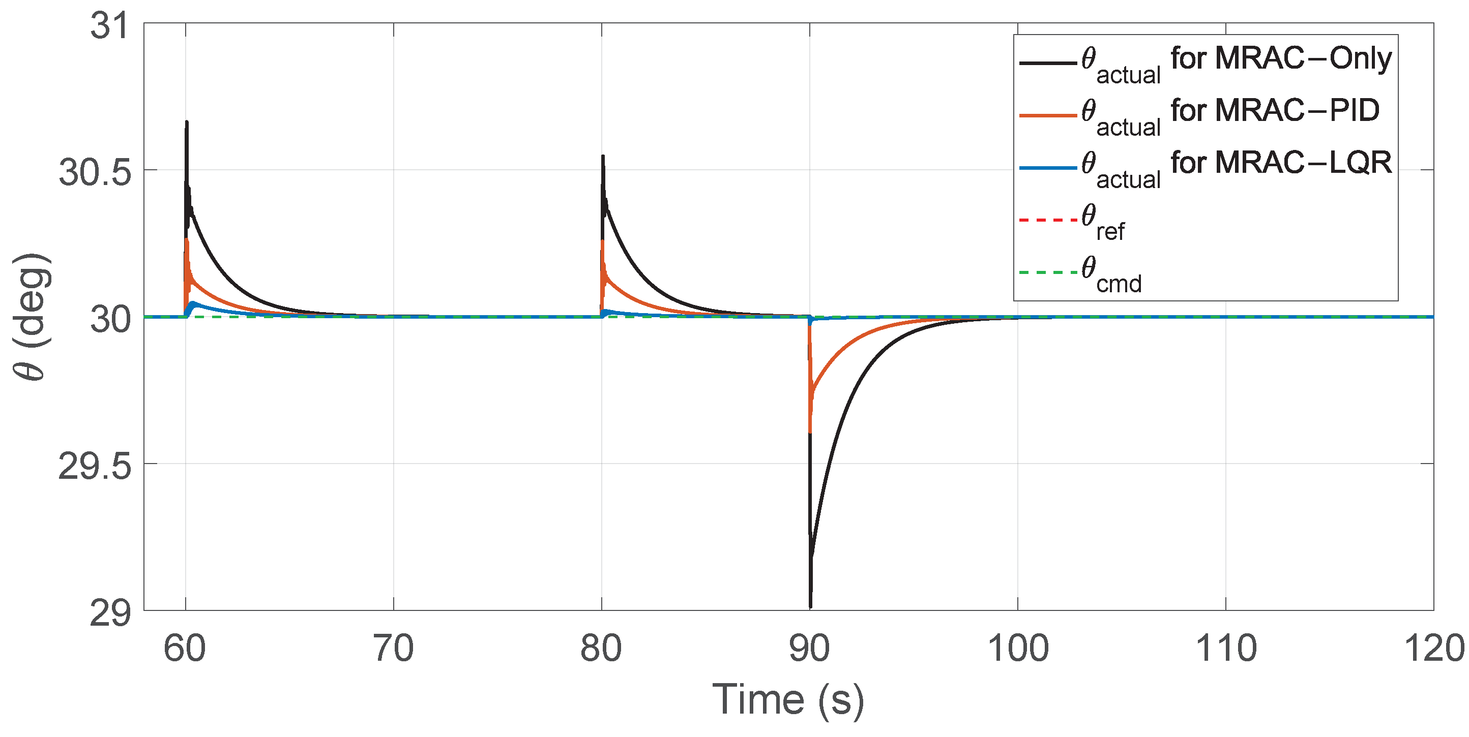
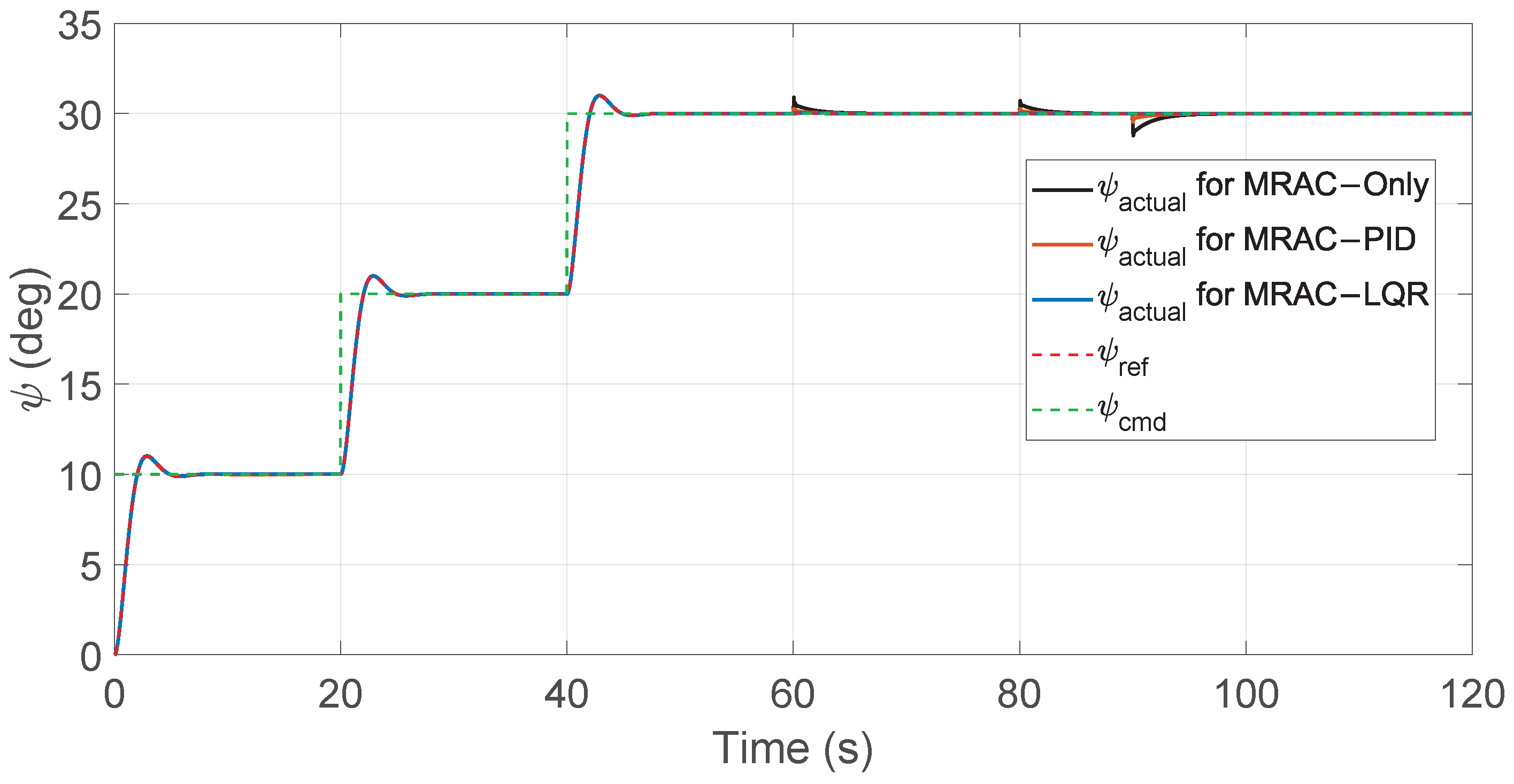
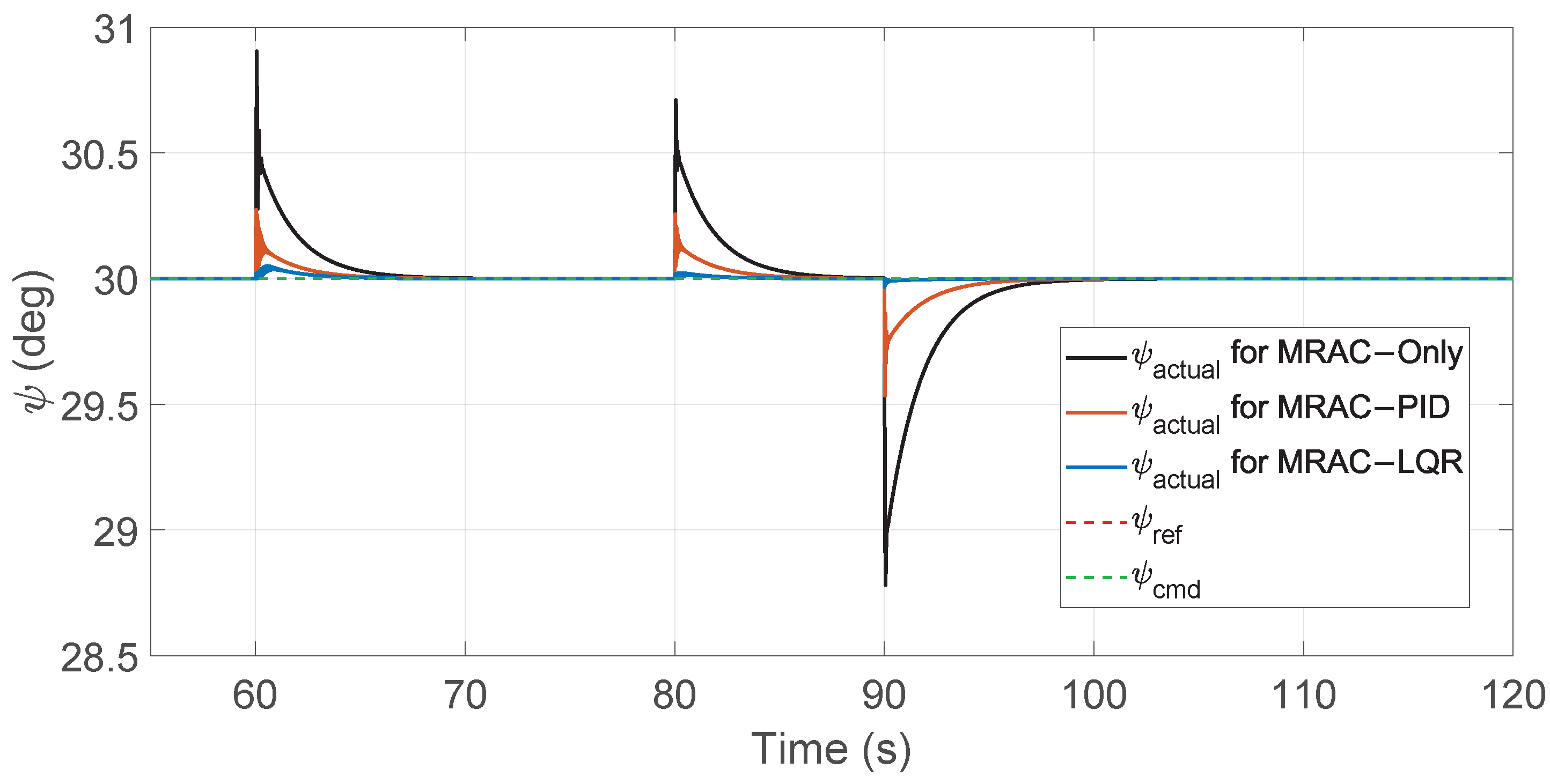
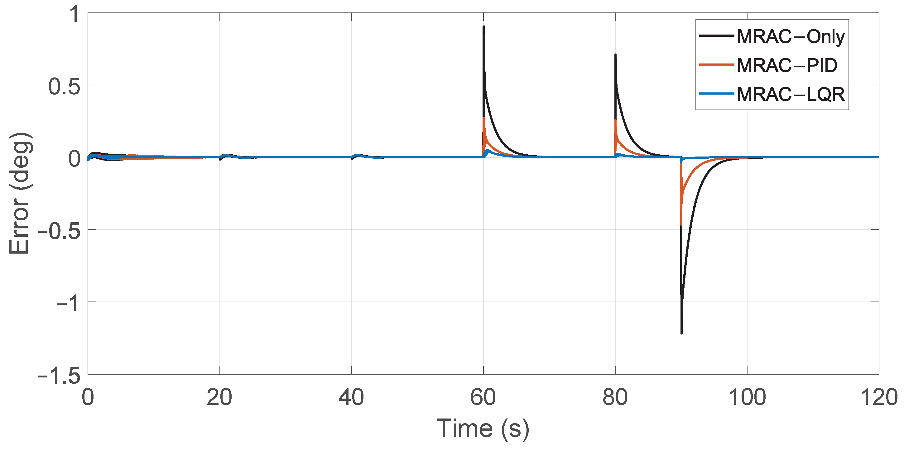
Similarly, for the attitude responses, all the implemented schemes of MRAC successfully tracked the reference model. The roll responses are shown in Figure 10 and Figure 11, with the corresponding roll tracking errors in Figure 12. The pitch responses are shown in Figure 13 and Figure 14, with the corresponding pitch tracking errors in Figure 15. The yaw responses are shown in Figure 16 and Figure 17, with the corresponding yaw tracking errors in Figure 18. From the zoomed views in Figure 11, Figure 14 and Figure 17, it can be observed that MRAC–LQR provided the best tracking performance, with minimal deviations when disturbances were applied at 60 s and 80 s, and again when the disturbances were fully removed at 90 s.
Furthermore, the tracking errors presented in Figure 12, Figure 15 and Figure 18 indicate that the attitude tracking errors during changes in the command inputs were limited to around 0 . 1 only, unlike in the case of the altitude, where it had larger deviation whenever the command changed. Moreover, it can be observed that the largest errors occurred when the wind force was totally removed at 90 s. This significant error is due to the MRAC adapting its gains based on the continuous disturbances applied at 60 s and 80 s. Likewise, as in the altitude case, the sudden drop from 10 N to zero caused a spike because the adaptive gains had previously been adjusted to compensate for the 10 N disturbance. Therefore, the MRAC had to make significant changes to the gain values to operate perfectly under disturbance-free conditions.
A comparison of peak errors and MSE values for all three variations of the MRAC controller for attitude is summarized in Section 7.

6.3. Controller Input Smoothness and Peaks

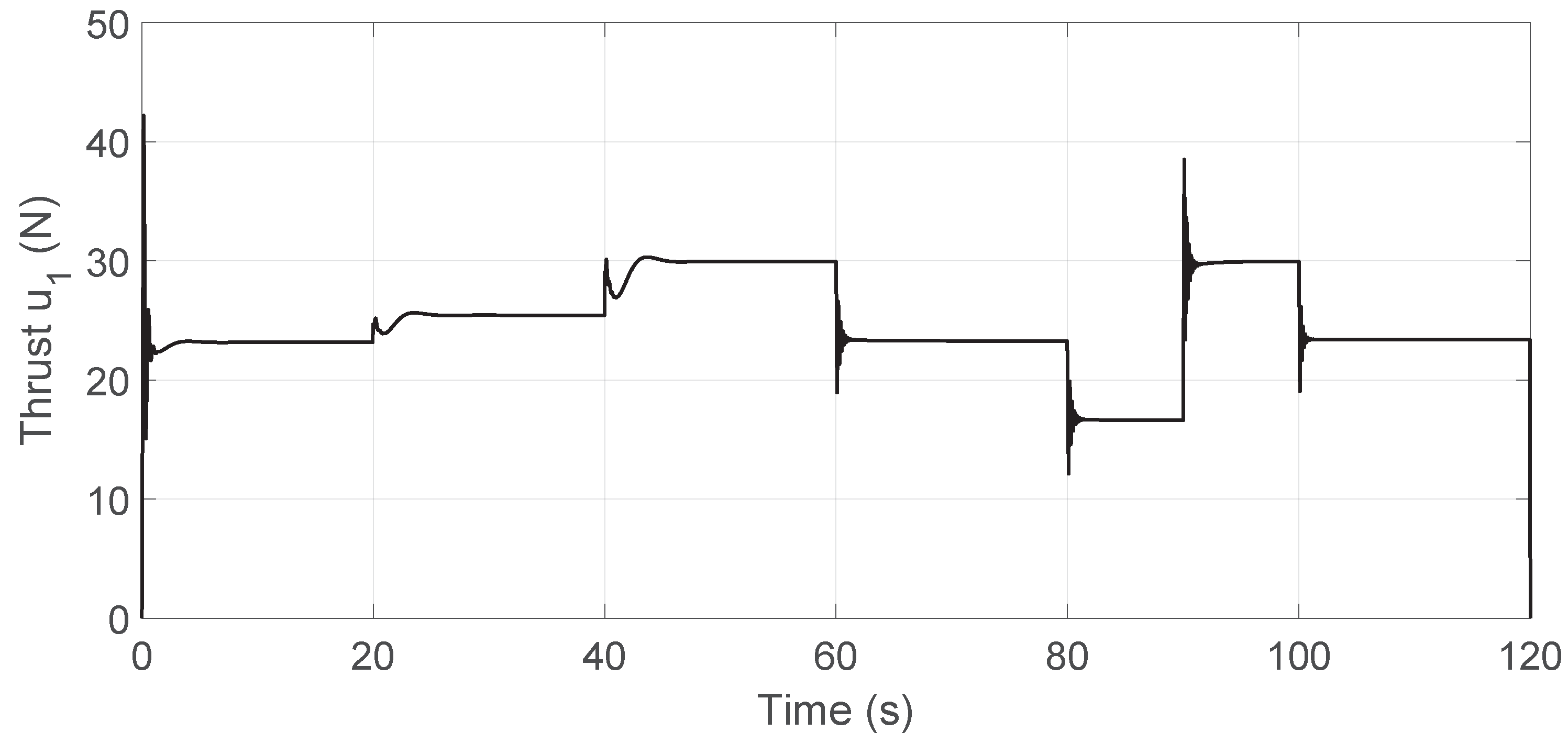
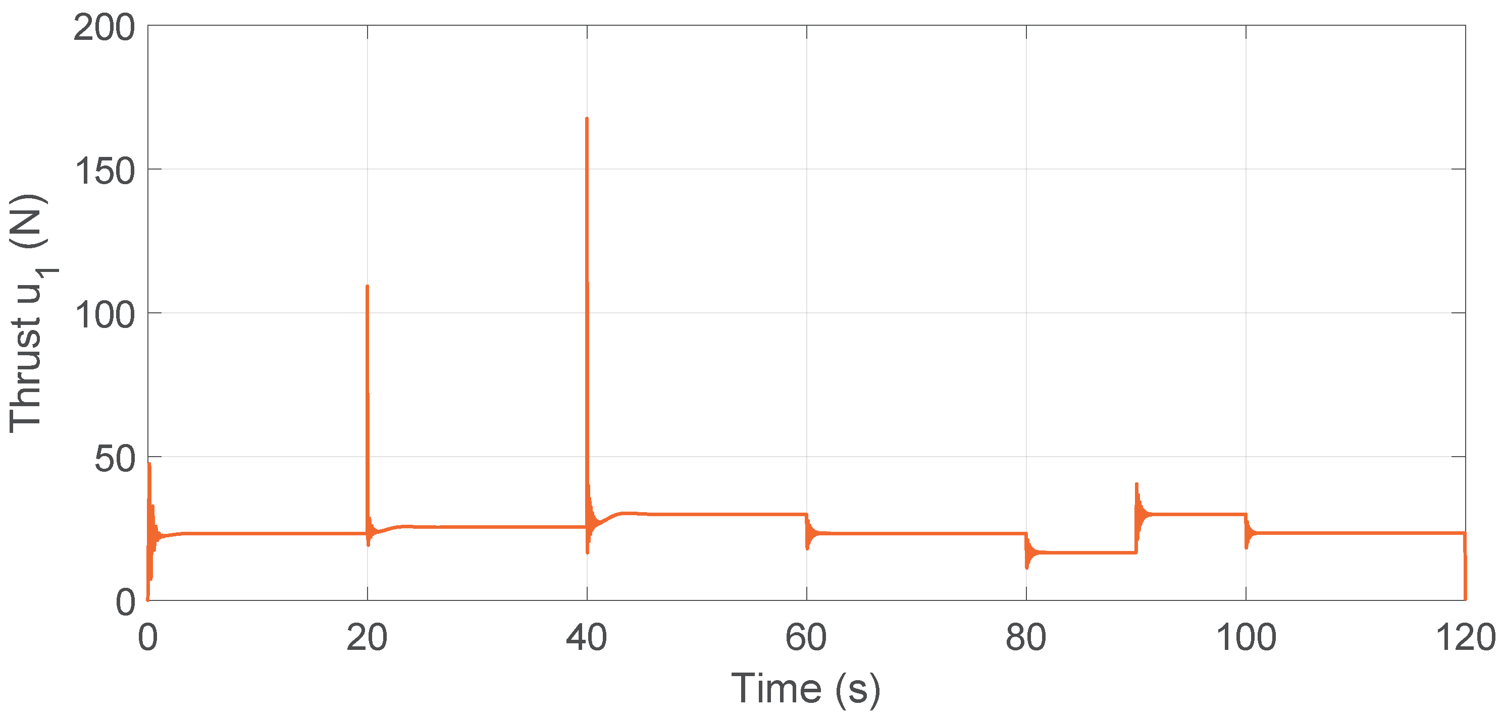
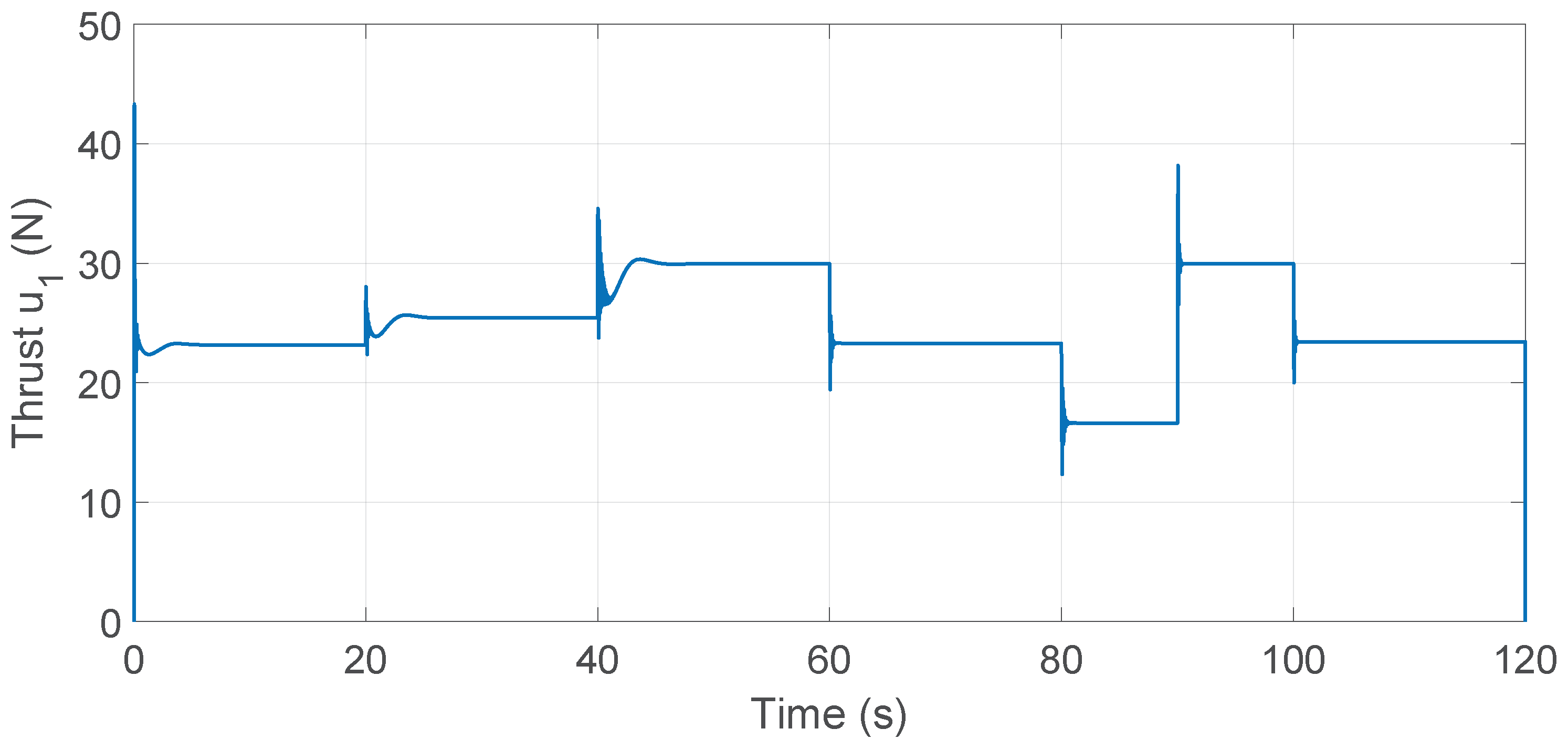
Another important comparison involves the control inputs since the rotor speed is directly related to the collective thrust u 1 required to sustain the quadrotor’s altitude. As shown in Figure 19, Figure 20, Figure 21 and Figure 22, all three controllers increase thrust immediately to counter gravity and achieve the first altitude setpoint then adjust dynamically to accommodate subsequent step commands, wind disturbances, and mass changes.
Figure 19 shows that the thrust input u 1 for the standalone MRAC reached approximately 42.2 N at the start, which was its maximum value. In contrast, for the MRAC–PID controller (Figure 20), the initial thrust was higher at 47.1 N, and a significantly larger spike occurred at 40 s when the altitude command was increased to 2 m, peaking at 167.6 N. For the MRAC–LQR controller (Figure 22), the thrust also peaked around 42.2 N at the start, similar to the standalone MRAC, but exhibited sharper oscillations between events compared with the smoother response of the standalone MRAC.
These results indicate that, among the three configurations, the MRAC–PID controller has the highest risk of actuator saturation due to its extreme thrust peaks. Such peaks could lead to instability, degraded tracking performance, or complete control loss if the motors are driven beyond their physical limits.
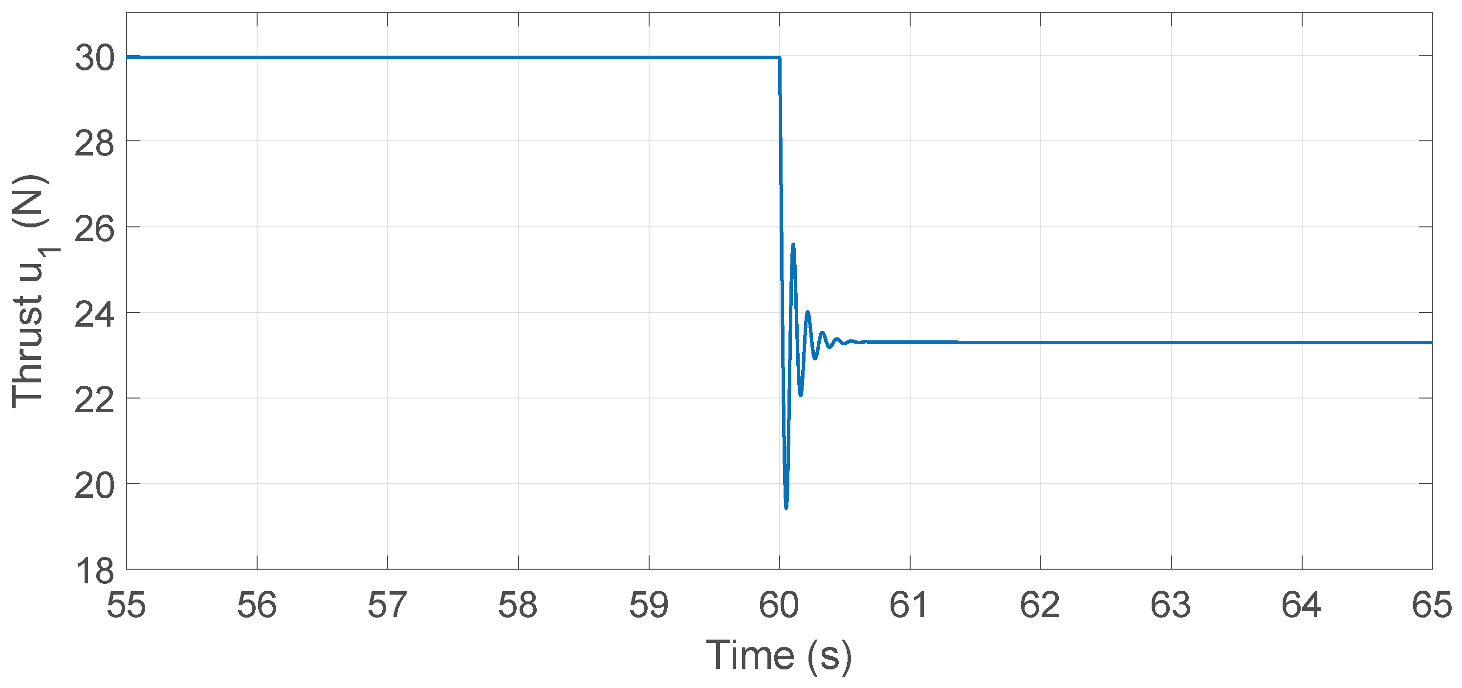
As shown in Figure 21 and Figure 23, a closer inspection of the thrust input u 1 around t = 60 s highlights the transient response differences among the controllers. The MRAC–PID exhibits larger oscillations in response to disturbance, whereas the cascaded MRAC–LQR achieves faster settling with smaller oscillations, demonstrating improved transient behavior of the cascaded design during thrust adjustments.

6.4. Rotor Speed Comparison

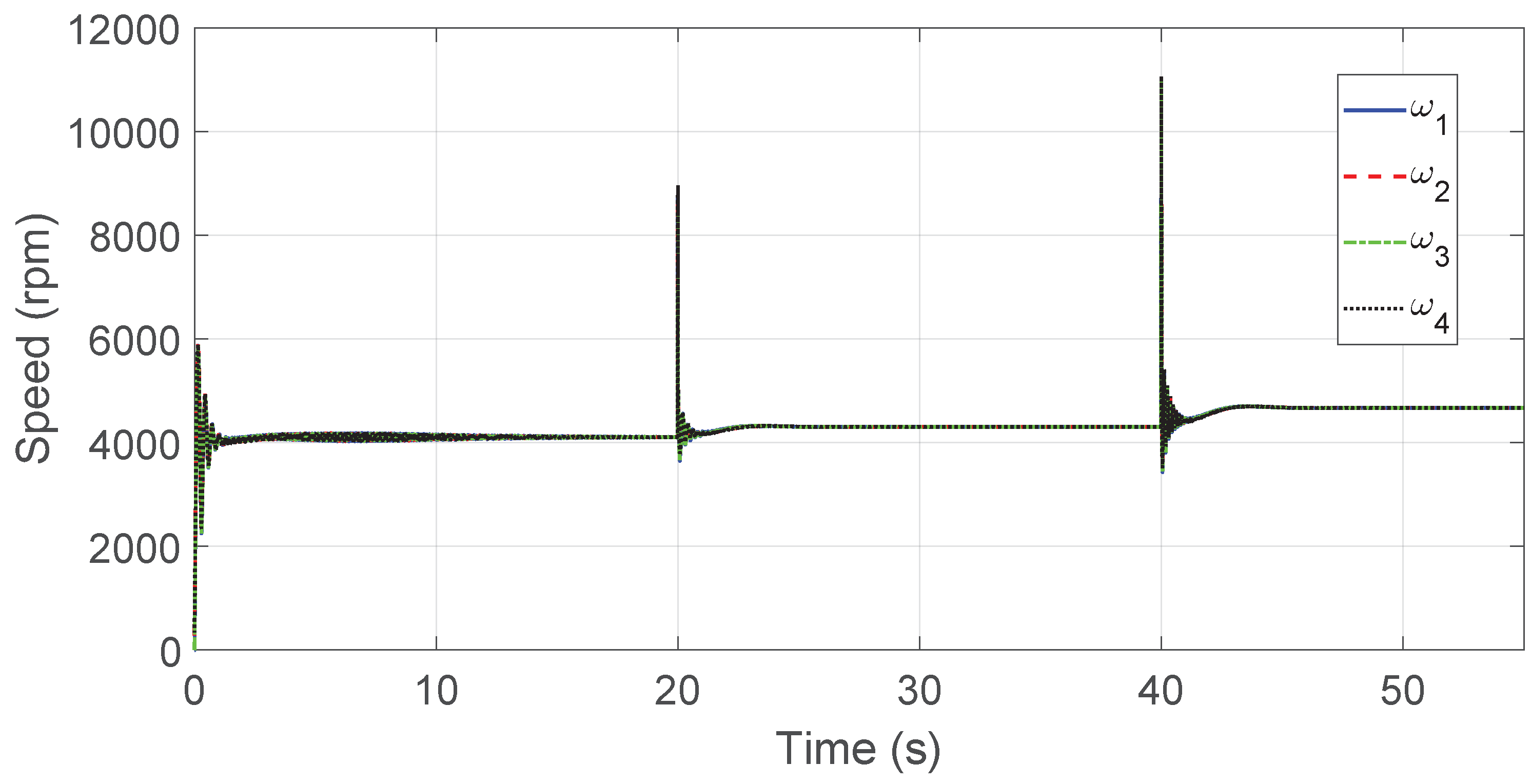
Using RCbenchmark [37], the maximum measured rotor speed was approximately 700 rad / s , equivalent to about 6700 RPM . The rotor-mixing equations in (96)–(99) were used to compute the individual motor speeds from the total thrust u 1 and the attitude control inputs u 2 , u 3 , and u 4 . Under the three altitude step inputs, all controllers commanded progressively higher rotor speeds, as shown in Figure 24, Figure 25 and Figure 26.
ω 1 2 = u 1 4 K T u 3 2 K T L u 4 4 K d ,
ω 2 2 = u 1 4 K T u 2 2 K T L + u 4 4 K d ,
ω 3 2 = u 1 4 K T + u 3 2 K T L u 4 4 K d ,
ω 4 2 = u 1 4 K T + u 2 2 K T L + u 4 4 K d .
For the MRAC and MRAC–LQR controllers, rotor speeds peaked at approximately 5000 RPM during the 2 m step input. This is within the 6700 RPM hardware limit, indicating that both controllers operate safely under high-demand conditions. Although MRAC–LQR exhibits additional oscillations due to the LQR feedforward term, its rotor speeds remain below the measured limit. In contrast, the MRAC–PID controller produced significant overshoot, with rotor speeds exceeding 11 , 000 RPM . This is far above the maximum safe operating limit and introduces a risk of motor saturation, excessive power draw, or structural damage due to overspeeding. Overall, from the perspective of rotor-speed constraints, MRAC and MRAC–LQR are both within acceptable bounds, whereas MRAC–PID exceeds the limits and would require gain tuning or additional constraints to ensure safe operation.

6.5. Thrust Saturation Strategy

In the final controller implementation, only the collective thrust channel U 1 will be subject to saturation, enforcing its output to remain within the verified 0–45 N range while the attitude torque commands U 2 , U 3 , U 4 pass through unchanged. This saturation is applied immediately before the rotor-mixing step as follows:
U ˜ 1 = sat U 1 , 0 , 45 N ,
where U ˜ 1 is the bounded thrust command. The saturated value U ˜ 1 , together with the original U 2 , U 3 , U 4 , is then converted to motor angular velocities via (96)–(99). This single-channel limiter ensures that motor thrust remains within the rotor capability while preserving the dynamic response characteristics demonstrated in simulation.

6.6. Computational Burden

The proposed cascaded MRAC–LQR controller does not introduce significant additional computational effort compared with a standard MRAC structure. The online calculations consist mainly of vector–matrix multiplications for the adaptive update law and evaluation of the fixed LQR feedback term, both of which are lightweight operations for real-time implementation. All simulations were performed in MATLAB 2024b on a workstation equipped with an Intel Xeon E3-1220 v5 CPU (3.0 GHz) and 40 GB RAM. As a representative measure, a 10 s nonlinear simulation with the cascaded MRAC–LQR controller required approximately 0.0509 s of CPU time, indicating that the controller can be run comfortably in real time. Since the Riccati equation is solved offline and no iterative optimization is performed during operation, the computational requirements remain similar to those of the MRAC–PID and parallel MRAC–LQR baselines used for comparison.

6.7. Robustness

The simulation scenarios were designed to evaluate the robustness of each controller under realistic and challenging operating conditions. The introduction of large step-wise wind forces (Table 5), as well as the sudden 0.5 kg mass change at t = 100 s, forces the adaptive laws to readjust while the system dynamics change abruptly. These disturbances were applied along all three body axes to introduce cross-coupling effects and to test the controllers under both matched and unmatched uncertainties. As shown in Figure 7, Figure 8, Figure 9, Figure 10, Figure 11, Figure 12, Figure 13, Figure 14, Figure 15, Figure 16, Figure 17 and Figure 18, all controllers maintain stable tracking behavior under these demanding conditions, with the cascaded MRAC–LQR exhibiting the smallest transient deviations. These results demonstrate that the proposed controller provides strong robustness to both external disturbances and rapid variations in system parameters.

6.8. Sensitivity of the MRAC Update Parameters

The learning-rate constants γ used in the MRAC update laws were optimized using the Nelder–Mead search method, as described in Section 5.2. Although these values are fixed for all simulations, the test scenarios introduce conditions where the ideal adaptive gains would temporarily differ, such as the sudden 0.5 kg mass drop and the abrupt changes in wind forces (Table 5). These changes effectively create a mismatch between the actual learning rates and the values that would be optimal at each moment. As shown in the transient responses (Figure 7 and Figure 8), the cascaded MRAC–LQR remains stable and shows the smallest deviations during these events. This indicates that the controller is not overly sensitive to moderate mismatch in the adaptive parameters and can maintain reliable tracking even when the system dynamics change suddenly.

7. Discussion

All simulations used the same identified quadrotor model parameters (Table 1), including mass, moments of inertia, thrust and drag coefficients, and rotor arm length. The same command profile (Table 4), wind disturbance schedule (Table 5), and mass variation test were applied to each controller. By keeping these conditions identical across all runs, only the adaptive learning-rate values γ and the controller structures influenced the observed performance. This setup ensures a fair basis for comparing the MSE and peak error metrics presented in this section.

7.1. MSE Comparison for MRAC Controllers

The MSE for each controller variation was computed over the full simulation as:
MSE = 1 N i = 1 N x system x ref 2 .
where x plant is the simulated state and x ref is the corresponding reference model state. The calculated MSE values are summarized in Table 6.
The hybrid MRAC–PID improved performance relative to the standalone MRAC by reducing the altitude MSE from 2.48 × 10 5 to 7.76 × 10 6 , corresponding to
2.48 × 10 5 7.76 × 10 6 2.48 × 10 5 × 100 % 68.7 % .
The corresponding reductions were 86.1% for roll, 89% for pitch, and 93% for yaw. The cascaded MRAC–LQR achieved the largest improvement, reducing the altitude MSE from 2.48 × 10 5 to 1.16 × 10 6 , a reduction of approximately 95.3%. The roll, pitch, and yaw MSE were reduced by 99.7%, 99.7%, and 99.8%, respectively. These results confirm that integrating PID or LQR with MRAC enhances tracking accuracy. Among the three, the cascaded MRAC–LQR delivered the greatest overall improvement in both tracking performance and MSE.

7.2. Altitude and Attitude Peak Error Analysis

Table 7, Table 8, Table 9 and Table 10 summarize the peak tracking errors of each controller under different test conditions, including command changes, wind disturbances, and parameter variations. All three MRAC configurations rejected disturbances effectively and maintained low tracking errors; however, the MRAC–LQR consistently achieved the smallest deviations, demonstrating the highest robustness among the three. A notable observation from Table 7, Table 8, Table 9 and Table 10 is that at the start of the simulation, MRAC–LQR exhibited significantly smaller tracking errors than both the standalone MRAC and the MRAC–PID. This result confirms that the LQR component improves the system’s initial response, enabling faster acquisition of altitude and attitude. It also shows that the LQR mitigates the effect of the early adaptation phase, as the standalone MRAC starts with all adaptive gains set to zero, which causes an initial error spike, whereas the LQR provides immediate correction while the MRAC gains converge. Table 11 summarizes the average performance improvements of the MRAC–PID and MRAC–LQR controllers relative to the standalone MRAC.

7.3. Alternative MRAC–LQR Scheme: Parallel Combination

Several existing studies have explored MRAC–LQR combinations with different structural arrangements. A commonly used configuration runs MRAC and a fixed-gain LQR in parallel, with their control signals summed to form the plant input. In this structure, both controllers respond directly to the commanded input but operate on different principles. The LQR uses the error between the plant output and the command input, while the MRAC uses the error between the plant output and a reference model. The MRAC ensures robustness to parameter variations and unmodeled dynamics, whereas the LQR provides optimal regulation around a nominal linear model. This parallel MRAC–LQR structure has been applied to quadrotor systems by Lee [22] and later extended by Alia [24], showing improved tracking and disturbance rejection relative to standalone MRAC. Figure 27 shows a generic parallel configuration. The input command is sent to both the MRAC and LQR controllers. The outputs U LQR and U MRAC are summed and applied to the plant.

7.3.1. Tracking Performance of the Parallel MRAC–LQR Controller

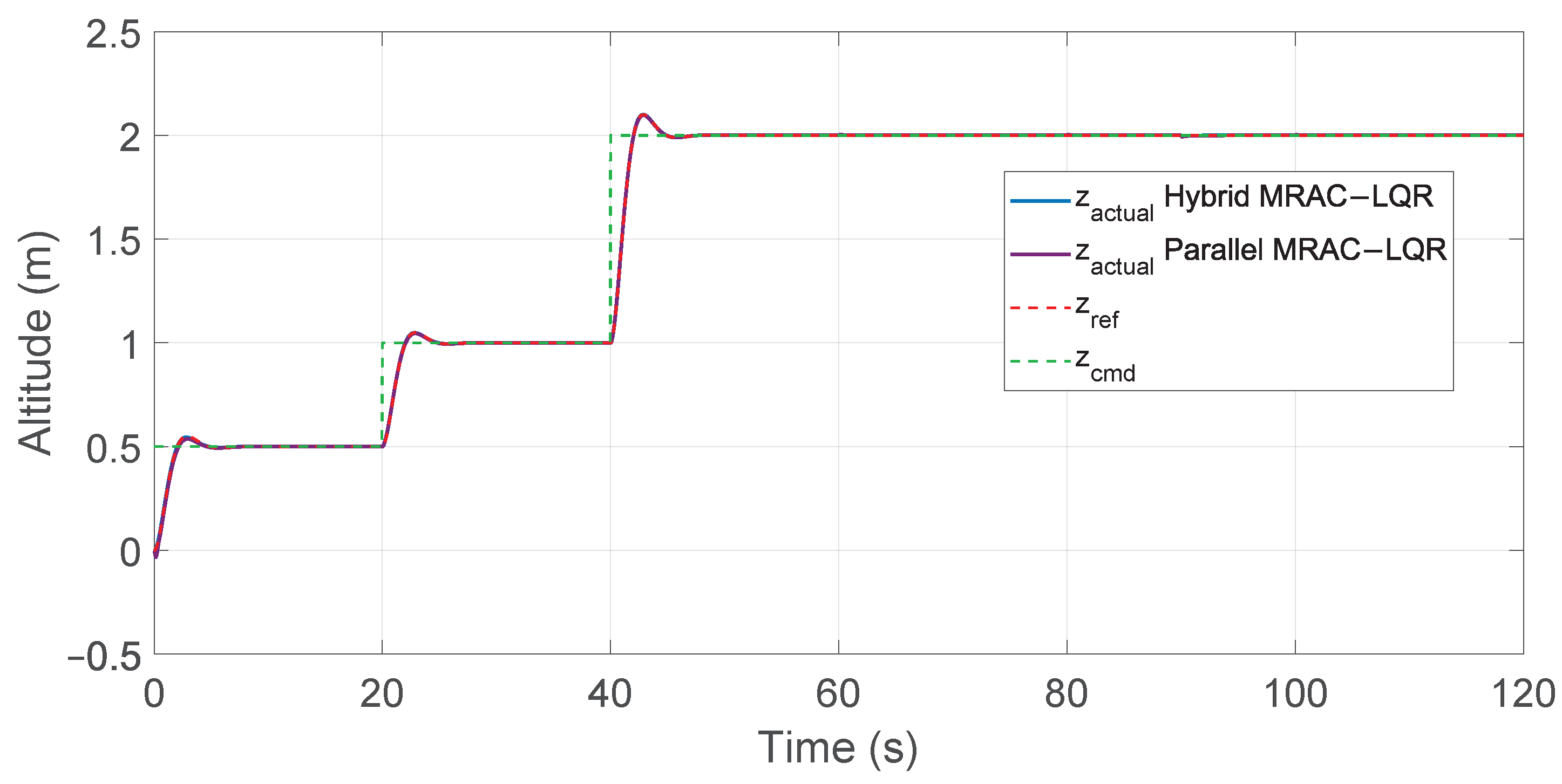
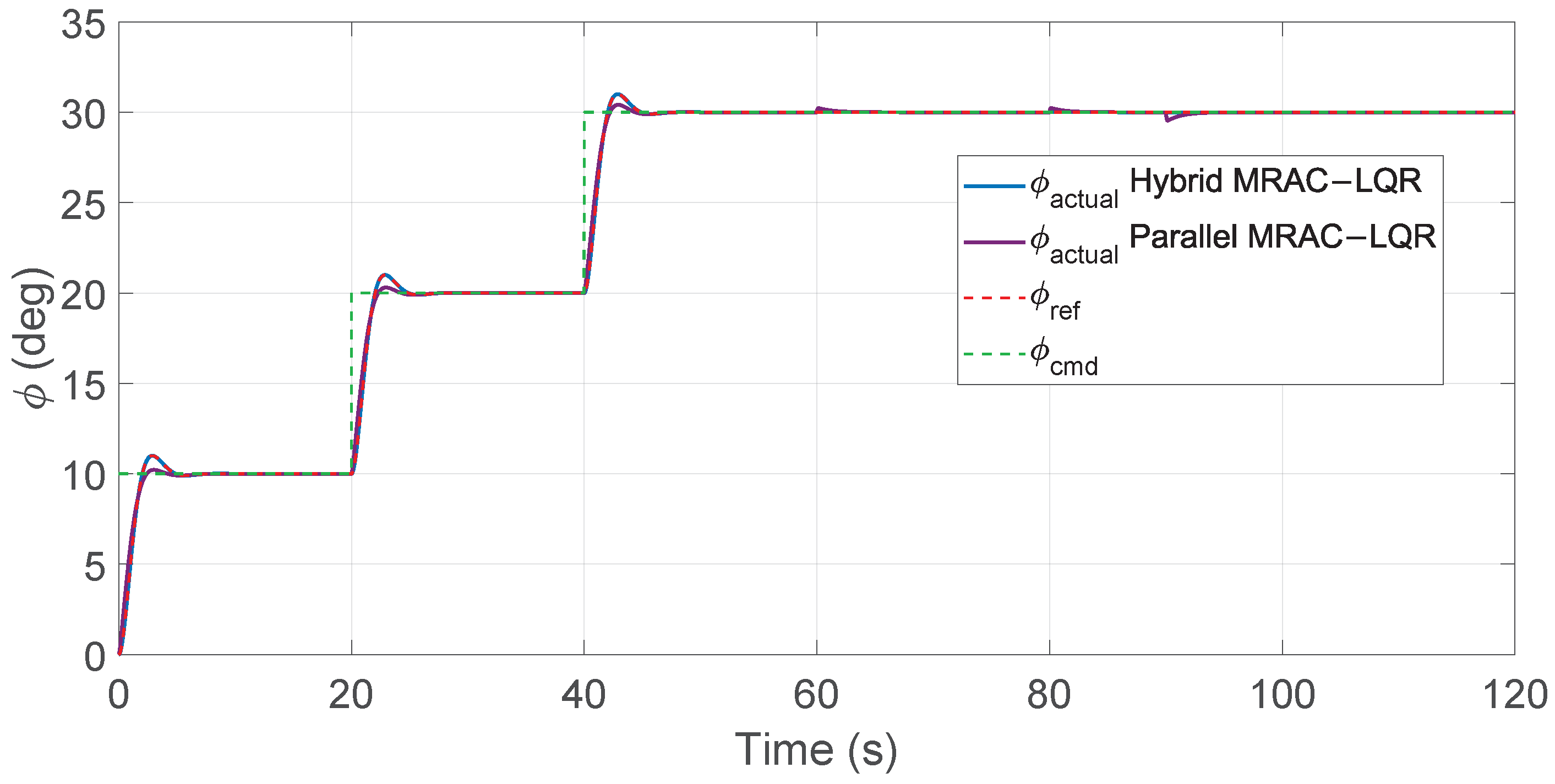
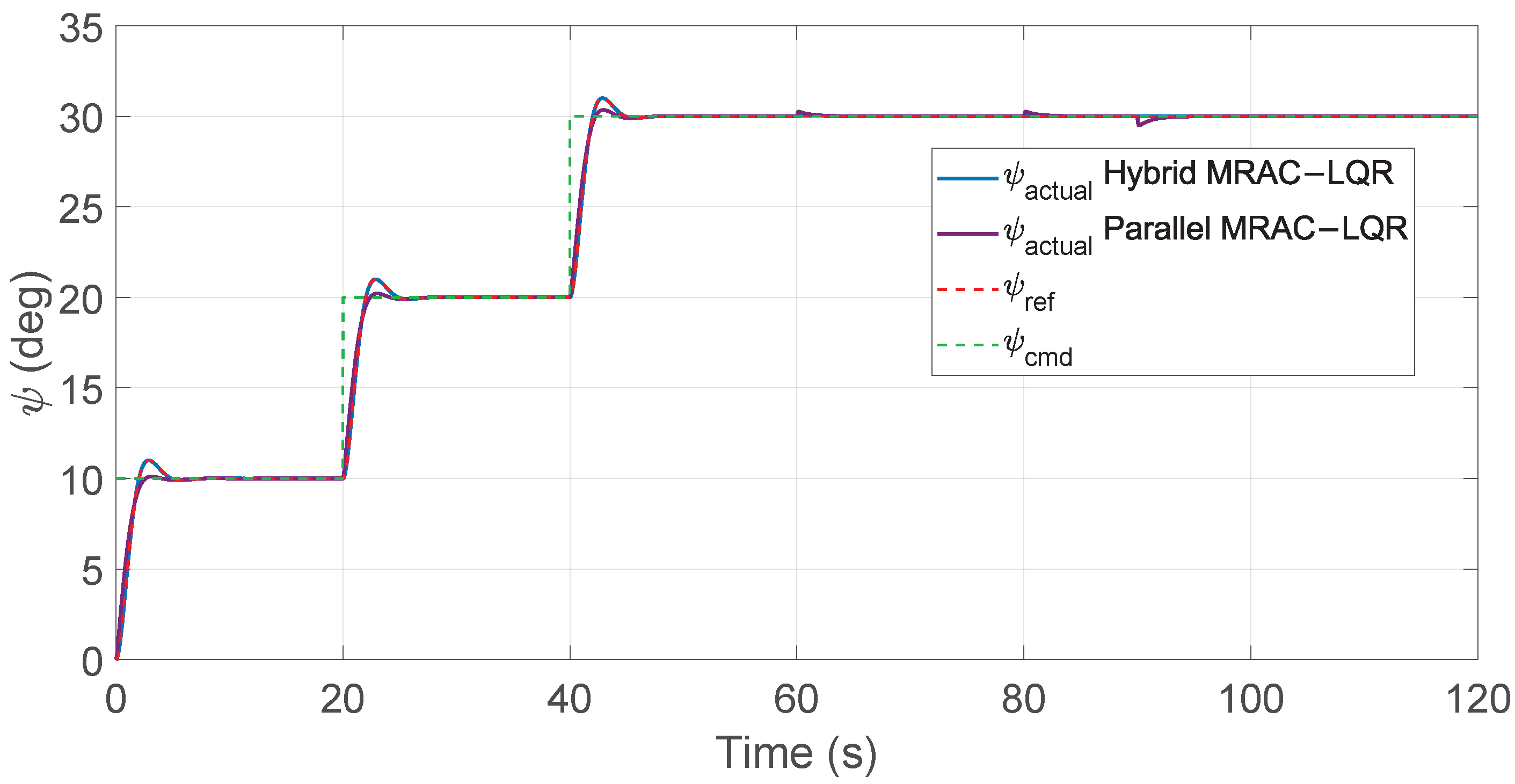
To assess the performance of the parallel architecture, the same command profile and disturbance timeline used in the cascaded hybrid MRAC–LQR simulations were applied. The altitude, roll, pitch, and yaw tracking results are shown in Figure 28, Figure 29, Figure 30 and Figure 31. The corresponding zoomed transient responses are given in Figure 32, Figure 33, Figure 34 and Figure 35, while the disturbance-rejection behavior is highlighted in Figure 36, Figure 37, Figure 38 and Figure 39, where both MRAC–LQR schemes are presented for comparison. These include the hybrid configuration proposed in this paper and the parallel variant adopted from the literature.
In the parallel scheme, the plant trajectory does not necessarily follow the reference model, since the LQR feedback is not involved in the model-following adaptation loop. As a result, the LQR controller regulates the nominal dynamics independently, while the MRAC compensates for uncertainties and disturbances. The response of the parallel scheme tends to remain closer to the input command. However, as summarized in Table 12 and Table 13, it exhibits larger peak deviations during wind disturbances and mass variation, indicating reduced robustness compared to the hybrid configuration.

7.3.2. Disturbance Robustness Comparison of MRAC–LQR Architectures

A direct mean-squared error (MSE) comparison between the two MRAC–LQR architectures is not meaningful, since they use different reference signals for error computation. The cascaded hybrid MRAC–LQR presented in this paper computes the tracking error with respect to a reference model, while the parallel MRAC–LQR computes the error relative to the input command. Due to this mismatch in error definitions, a unified MSE metric cannot be used. Instead, disturbance rejection is assessed based on the peak deviations observed during wind disturbances (5 N and 10 N) and 0.5 kg quadrotor mass drop. The evaluation spans the interval from 60 to 120 s, as summarized in Table 12 and Table 13.
The results show that the cascaded hybrid MRAC–LQR consistently yields smaller peak deviations across all test scenarios, indicating superior disturbance rejection and faster recovery. This improvement is attributed to the integration of the LQR loop within the MRAC architecture, allowing the adaptive mechanism to respond more effectively to changes in system dynamics. In contrast, the parallel architecture applies LQR and MRAC outputs independently, without mutual coupling, which limits its effectiveness to time-varying uncertainties and external disturbances.

8. Conclusions

This work evaluated Model Reference Adaptive Control (MRAC) and its two hybrid schemes, MRAC–PID and MRAC–LQR, for quadrotor stabilization under command changes, wind disturbances, and sudden mass variation. The standalone MRAC maintained low MSE and tracking error across all test conditions.
Both hybrids reduced peak errors and MSE under identical conditions. The MRAC–PID controller produced lower tracking error but introduced sharp spikes in the control input, increasing the risk of actuator saturation. In contrast, MRAC–LQR generated smoother control inputs, faster tracking, and improved disturbance rejection. Quantitatively, MRAC–PID reduced altitude MSE by 68.7%, roll by 86.1%, pitch by 89%, and yaw by 93% compared with the standalone MRAC. MRAC–LQR provided the greatest improvement, reducing altitude MSE by 95.3% and roll, pitch, and yaw MSE by 99.7%, 99.7%, and 99.8%, respectively. These gains were achieved with moderate control effort and robustness to disturbances and parameter variations. Additionally, a parallel MRAC–LQR that sums MRAC and LQR outputs was implemented for comparison. It tracked acceptably but showed larger peak deviations and weaker disturbance rejection than the cascaded MRAC–LQR. Therefore, the proposed controller demonstrates the most balanced and reliable performance. The outer LQR loop provides fast nominal response, while the inner MRAC loop adaptively compensates for nonlinearities, modeling uncertainties, and external disturbances, yielding superior overall performance for quadrotor stabilization.
In the next phase, the hybrid controllers will undergo hardware in the loop (HIL) testing and flight trials on a laboratory-built quadrotor. These experiments will validate the adaptive controller under sensor noise, actuator limits, and latency and confirm performance beyond simulation. This platform will also benchmark the MRAC–LQR scheme against MRAC and MRAC–PID under identical conditions. Future work will compare optimization methods to further improve the hybrid MRAC framework.

Author Contributions

Conceptualization, A.A.A. and I.H.; methodology, A.A.A.; software, A.A.A.; validation, A.A.A., I.H. and R.D.; formal analysis, A.A.A.; investigation, A.A.A.; resources, A.A.A. and R.D.; data curation, A.A.A.; writing—original draft preparation, A.A.A.; writing—review and editing, A.A.A., I.H. and R.D.; visualization, A.A.A. and R.D.; supervision, R.D.; project administration, R.D. All authors have read and agreed to the published version of the manuscript.

Funding

The work in this paper was supported by the American University of Sharjah. This paper represents the opinions of the authors and does not mean to represent the position or opinions of the American University of Sharjah.

Data Availability Statement

The original contributions presented in this study are included in this article. Further inquiries can be directed to the corresponding author.

Conflicts of Interest

The authors declare no conflicts of interest.

Abbreviations

The following abbreviations are used in this manuscript:
MRACModel Reference Adaptive Control
LQRLinear Quadratic Regulator
PIDProportional-Integral-Derivative
MSEMean Squared Error
UAVUnmanned Aerial Vehicle
MIMOMultiple-Input Multiple-Output

References

  1. Husain, S.M.A.; Ahmad, S.Y.; Aziz, A.; Sohail, S.S. Drone for Agriculture: A way forward. In Proceedings of the 2022 International Conference on Data Analytics for Business and Industry (ICDABI), Sakhir, Bahrain, 25–26 October 2022; pp. 580–586. [Google Scholar] [CrossRef]
  2. Garg, V.; Niranjan, S.; Prybutok, V.; Pohlen, T.; Gligor, D. Drones in last-mile delivery: A systematic review on Efficiency, Accessibility, and Sustainability. Transp. Res. Part D Transp. Environ. 2023, 123, 103831. [Google Scholar] [CrossRef]
  3. Mahajan, A. Applications of Drone Technology in Construction Industry: A Study 2012-2021. Int. J. Eng. Adv. Technol. 2021, 11, 224–239. [Google Scholar] [CrossRef]
  4. Ya’acob, N.; Zolkapli, M.; Johari, J.; Yusof, A.L.; Sarnin, S.S.; Asmadinar, A.Z. UAV environment monitoring system. In Proceedings of the 2017 International Conference on Electrical, Electronics and System Engineering (ICEESE), Kanazawa, Japan, 9–10 November 2017; pp. 105–109. [Google Scholar] [CrossRef]
  5. Ataei, A.; Paschalidis, I.C. Quadrotor deployment for emergency response in smart cities: A robust MPC approach. In Proceedings of the 2015 54th IEEE Conference on Decision and Control (CDC), Osaka, Japan, 15–18 December 2015; pp. 5130–5135. [Google Scholar] [CrossRef]
  6. Tilak, G. Drones and media industry. RUDN J. Stud. Lit. Journal. 2020, 25, 360–366. [Google Scholar] [CrossRef]
  7. Shauqee, M.N.; Rajendran, P.; Mohd Suhadis, N. Quadrotor Controller Design Techniques and Applications Review. INCAS Bull. 2021, 13, 179–194. [Google Scholar] [CrossRef]
  8. SONUGÜR, G. A Review of quadrotor UAV: Control and SLAM methodologies ranging from conventional to innovative approaches. Robot. Auton. Syst. 2023, 161, 104342. [Google Scholar] [CrossRef]
  9. Krstić, M.; Kanellakopoulos, I.; Kokotović, P.V. Nonlinear and Adaptive Control Design; John Wiley & Sons: New York, NY, USA, 1995. [Google Scholar]
  10. Utkin, V.I. Sliding Modes in Control and Optimization; Springer: Berlin/Heidelberg, Germany, 1992. [Google Scholar]
  11. Bouabdallah, S. Design and Control of Quadrotors with Application to Autonomous Flying. Ph.D. Thesis, École Polytechnique Fédérale de Lausanne (EPFL), Lausanne, Switzerland, 2007. [Google Scholar] [CrossRef]
  12. Noordin, A.; Basri, A.; Mohamed, Z. Real-Time Implementation of an Adaptive PID Controller for the Quadrotor MAV Embedded Flight Control System. Aerospace 2023, 10, 59. [Google Scholar] [CrossRef]
  13. Jurado, F.; Lopez, S.; Dzul, A.; Rodríguez-Cortes, H. Decentralized direct MRAC for attitude control of a quadrotor UAV. In Proceedings of the 2017 14th International Conference on Electrical Engineering, Computing Science and Automatic Control (CCE), Mexico City, Mexico, 20–22 October 2017; pp. 1–6. [Google Scholar] [CrossRef]
  14. Selfridge, J.M.; Tao, G. A multivariable adaptive controller for a quadrotor with guaranteed matching conditions. In Proceedings of the 2014 American Control Conference (ACC), Portland, OR, USA, 4–6 June 2014; pp. 1–6. [Google Scholar] [CrossRef]
  15. Selfridge, J.M.; Tao, G. Multivariable output feedback MRAC for a quadrotor UAV. In Proceedings of the 2016 American Control Conference (ACC), Boston, MA, USA, 6–8 July 2016; pp. 492–499. [Google Scholar] [CrossRef]
  16. Ristevski, S.; Koru, A.T.; Yucelen, T.; Dogan, K.M.; Muse, J.A. Experimental results of a quadrotor UAV with a model reference adaptive controller in the presence of unmodeled dynamics. In Proceedings of the AIAA SCITECH 2022 Forum, San Diego, CA, USA, 3–7 January 2022; pp. 1–11. [Google Scholar] [CrossRef]
  17. Jiao, S.; Wang, J.; Hua, Y.; Zhuang, Y.; Yu, X. Trajectory-Tracking Control for Quadrotors Using an Adaptive Integral Terminal Sliding Mode under External Disturbances. Drones 2024, 8, 67. [Google Scholar] [CrossRef]
  18. Ahn, H.; Hu, M.; Chung, Y.; You, K. Sliding-Mode Control for Flight Stability of Quadrotor Drone Using Adaptive Super-Twisting Reaching Law. Drones 2023, 7, 522. [Google Scholar] [CrossRef]
  19. Ghaffar, A.F.A.; Richardson, T.; Greatwood, C. A combined model reference adaptive control law for multirotor UAVs. IET Control Theory Appl. 2021, 15, 601–610. [Google Scholar] [CrossRef]
  20. Khan, M.A.A.; Swamy, M.S. Modified MRAC based on Lyapunov theory for improved controller efficiency. In Proceedings of the 2016 International Conference on Automatic Control and Dynamic Optimization Techniques (ICACDOT), Pune, India, 9–10 September 2016; pp. 989–995. [Google Scholar] [CrossRef]
  21. Gil, J.D.; Pataro, I.M.; Guzmán, J.; Berenguel, M. On the hybrid MRAC–PID control: A comparison study. IFAC-PapersOnLine 2024, 58, 37–42. [Google Scholar] [CrossRef]
  22. Lee, D.; Jang, K.; Lee, S.; Kim, L.; Bang, H. Closed-Loop MRAC Augmented LQR with Integral Action for Quadrotor UAV under the Uncertainties. In Proceedings of the 2022 CEAS EuroGNC Conference, Berlin, Germany, 3–5 May 2022. CEAS-GNC-2022-002. [Google Scholar]
  23. Ganapathy Subramanian, R.; Elumalai, V.K. Robust MRAC augmented baseline LQR for tracking control of 2 DoF helicopter. Robot. Auton. Syst. 2016, 86, 70–77. [Google Scholar] [CrossRef]
  24. Ghaffar, A.A.; Richardson, T. Model Reference Adaptive Control and LQR Control for Quadrotor with Parametric Uncertainties. Int. J. Mech. Mechatronics Eng. 2015, 9, 244–250. [Google Scholar]
  25. Sabatino, F. Quadrotor Control: Modeling, Nonlinear Control Design, and Simulation. Master’s Thesis, School of Electrical Engineering, KTH Royal Institute of Technology, Stockholm, Sweden, 2015. [Google Scholar]
  26. Luukkonen, T. Modelling and Control of Quadcopter. In Independent Research Project in Applied Mathematics; School of Science, Aalto University: Espoo, Finland, 2011. [Google Scholar]
  27. Hafez, I.; Dhaouadi, R. Hybrid Particle Swarm Optimization with Quasi-Newton Local Search for Quadrotor Altitude and Attitude Control. In Proceedings of the 2024 8th International Conference on Robotics and Automation Sciences (ICRAS), Tokyo, Japan, 21–23 June 2024; pp. 161–166. [Google Scholar] [CrossRef]
  28. Khalil, H.K. Nonlinear Systems, 3rd ed.; Prentice Hall: Upper Saddle River, NJ, USA, 2002. [Google Scholar]
  29. Tao, G. Adaptive Control Design and Analysis; John Wiley & Sons, Inc.: New York, NY, USA, 2003. [Google Scholar] [CrossRef]
  30. Lavretsky, E.; Wise, K.A. State Feedback Direct Model Reference Adaptive Control. In Robust and Adaptive Control: With Aerospace Applications; Springer International Publishing: Cham, Switherland, 2024; pp. 413–444. [Google Scholar] [CrossRef]
  31. Martins, L.; Cardeira, C.; Oliveira, P. Linear Quadratic Regulator for Trajectory Tracking of a Quadrotor. IFAC-PapersOnLine 2019, 52, 176–181. [Google Scholar] [CrossRef]
  32. Rinaldi, M.; Primatesta, S.; Guglieri, G. A Comparative Study for Control of Quadrotor UAVs. Appl. Sci. 2023, 13, 3464. [Google Scholar] [CrossRef]
  33. MathWorks. MATLAB and Simulink Release 2024a; The MathWorks, Inc.: Natick, MA, USA, 2024. [Google Scholar]
  34. Mustapa, Z.; Saat, S.; Husin, S.H.; Zaid, T. Quadcopter physical parameter identification and altitude system analysis. In Proceedings of the 2014 IEEE Symposium on Industrial Electronics & Applications (ISIEA), Kota Kinabalu, Malaysia, 28 September–1 October 2014; pp. 130–135. [Google Scholar] [CrossRef]
  35. Mechali, O.; Iqbal, J.; Xie, X.; Xu, L.; Senouci, A. Robust Finite-Time Trajectory Tracking Control of Quadrotor Aircraft via Terminal Sliding Mode-Based Active Antidisturbance Approach: A PIL Experiment. Int. J. Aerosp. Eng. 2021, 2021, 5522379. [Google Scholar] [CrossRef]
  36. Singer, S.; Nelder, J. Nelder-Mead algorithm. Scholarpedia 2009, 4, 2928. [Google Scholar] [CrossRef]
  37. Tyto Robotics. RCbenchmark Software; Tyto Robotics Inc.: Gatineau, QC, Canada, 2025. [Google Scholar]
Figure 1. Quadrotor body-fixed frame { B } relative to the inertial frame { G } .
Drones 09 00814 g001
Figure 2. MRAC block diagram.
Drones 09 00814 g002
Figure 3. MRAC-based control architecture for quadrotor altitude and attitude regulation.
Drones 09 00814 g003
Figure 4. Generalized MRAC controller for the quadrotor. Solid arrows indicate the signal flow, and dashed arrows represent the adaptation mechanism of the controller gains.
Drones 09 00814 g004
Figure 5. Block diagram of the cascaded MRAC–LQR controller. Solid arrows indicate the signal flow, and dashed arrows represent the adaptation mechanism of the controller gains.
Drones 09 00814 g005
Figure 6. Block diagram of the cascaded MRAC–PID controller. Solid arrows indicate the signal flow, and dashed arrows represent the adaptation mechanism of the controller gains.
Drones 09 00814 g006
Figure 7. Altitude tracking responses for standalone MRAC, MRAC–PID, and MRAC–LQR controllers.
Drones 09 00814 g007
Figure 8. Zoomed view of altitude responses between 55 s and 120 s illustrating disturbances and mass changes.
Drones 09 00814 g008
Figure 9. Altitude tracking errors for standalone MRAC, MRAC–PID, and MRAC–LQR controllers.
Drones 09 00814 g009
Figure 10. Roll angle tracking performance for MRAC controllers.
Drones 09 00814 g010
Figure 11. Zoomed view of roll angle tracking showing disturbance periods.
Drones 09 00814 g011
Figure 12. Roll angle tracking errors for MRAC controllers.
Drones 09 00814 g012
Figure 13. Pitch angle tracking performance for MRAC controllers.
Drones 09 00814 g013
Figure 14. Zoomed view of pitch angle tracking showing disturbance periods.
Drones 09 00814 g014
Figure 15. Pitch angle tracking errors for MRAC controllers.
Drones 09 00814 g015
Figure 16. Yaw angle tracking performance for MRAC controllers.
Drones 09 00814 g016
Figure 17. Zoomed view of yaw angle tracking showing disturbance periods.
Drones 09 00814 g017
Figure 18. Yaw angle tracking errors for MRAC controllers.
Drones 09 00814 g018
Figure 19. Control input u 1 for standalone MRAC.
Drones 09 00814 g019
Figure 20. Control input u 1 for MRAC–PID.
Drones 09 00814 g020
Figure 21. Zoomed view of the MRAC–PID thrust input u 1 around t = 60 s .
Drones 09 00814 g021
Figure 22. Control input u 1 for MRAC–LQR.
Drones 09 00814 g022
Figure 23. Zoomed view of the MRAC–LQR thrust input u 1 around t = 60 s .
Drones 09 00814 g023
Figure 24. Rotor speed for standalone MRAC under step inputs.
Drones 09 00814 g024
Figure 25. Rotor speed for MRAC–PID under step inputs.
Drones 09 00814 g025
Figure 26. Rotor speed for MRAC–LQR under step inputs.
Drones 09 00814 g026
Figure 27. Parallel MRAC–LQR: LQR and MRAC run in parallel on the same command, and their outputs are summed to form the plant input. Solid arrows indicate the signal flow, and dashed arrows represent the adaptive update signals from the adaptation mechanism to the controller gains.
Drones 09 00814 g027
Figure 28. Altitude tracking performance for hybrid and parallel MRAC–LQR controllers.
Drones 09 00814 g028
Figure 29. Roll angle tracking performance for hybrid and parallel MRAC–LQR controllers.
Drones 09 00814 g029
Figure 30. Pitch angle tracking performance for hybrid and parallel MRAC–LQR controllers.
Drones 09 00814 g030
Figure 31. Yaw angle tracking performance for hybrid and parallel MRAC–LQR controllers.
Drones 09 00814 g031
Figure 32. Zoomed view of transient response in altitude tracking for hybrid and parallel MRAC–LQR controllers.
Drones 09 00814 g032
Figure 33. Zoomed view of transient response in roll tracking for hybrid and parallel MRAC–LQR controllers.
Drones 09 00814 g033
Figure 34. Zoomed view of transient response in pitch tracking for hybrid and parallel MRAC–LQR controllers.
Drones 09 00814 g034
Figure 35. Zoomed view of transient response in yaw tracking for hybrid and parallel MRAC–LQR controllers.
Drones 09 00814 g035
Figure 36. Zoomed view of disturbance rejection in altitude tracking for hybrid and parallel MRAC–LQR controllers.
Drones 09 00814 g036
Figure 37. Zoomed view of disturbance rejection in roll tracking for hybrid and parallel MRAC–LQR controllers.
Drones 09 00814 g037
Figure 38. Zoomed view of disturbance rejection in pitch tracking for hybrid and parallel MRAC–LQR controllers.
Drones 09 00814 g038
Figure 39. Zoomed view of disturbance rejection in yaw tracking for hybrid and parallel MRAC–LQR controllers.
Drones 09 00814 g039
Table 1. Quadrotor model parameters used in simulation.
ParameterSymbolValue
Roll moment of inertia I x 0.02057 kg · m 2
Pitch moment of inertia I y 0.02097 kg · m 2
Yaw moment of inertia I z 0.03660 kg · m 2
Rotor inertia I p 0.01000 kg · m 2
Massm 2.29 kg
Gravityg 9.81 m / s 2
Thrust coefficient K T 3.13 × 10 5 N · s 2
Drag coefficient K d 7.50 × 10 7 N · m · s 2
Translational drag coeff. x K d x 2 × 10 4 N s m 1
Translational drag coeff. y K d y 3 × 10 4 N s m 1
Translational drag coeff. z K d z 5 × 10 4 N s m 1
Rotor arm lengthL 0.23 m
Table 2. Optimized MRAC learning-rate constants γ for altitude and attitude axes.
Axis γ γ r γ O γ d
Altitude 9.998 × 10 3 2.618 × 10 3 9.998 × 10 3
Roll 2144.08 I 2 × 2 3428.55 1001.87 1616.87
Pitch 1947.45 I 2 × 2 4228.72 1073.51 1549.09
Yaw 2073.74 I 2 × 2 3601.84 3357.13 1015.91
Table 3. Optimized PID gains used in the MRAC–PID controller.
Axis k p k i k d
Roll 10.81 2.96 0.0466
Pitch 16.00 3.00 0.0418
Yaw 6.72 3.34 0.0551
Altitude 0.0057 0.798 0.0050
Table 4. Command inputs applied to the nonlinear quadrotor model.
Time Interval (s)z (m) ϕ ( ) θ ( ) ψ ( )
0–200.50101010
20–401.00202020
40–1202.00303030
Table 5. Wind-force profile used in all tests.
Time Interval (s) f wx = f wy = f wz (N)Description
60–805Mild wind
80–9010Strong wind
90–1200No wind
Table 6. MSE values for the MRAC controllers.
ControllerAltitudeRollPitchYaw
MRAC 2.48 × 10 5 8.41 × 10 3 7.91 × 10 3 1.27 × 10 2
MRAC–PID 7.76 × 10 6 1.17 × 10 3 8.70 × 10 4 8.90 × 10 4
MRAC–LQR 1.16 × 10 6 2.56 × 10 5 2.60 × 10 5 3.13 × 10 5
Table 7. Altitude peak deviation comparison for MRAC controllers.
Time (s)Command/DisturbanceMRAC (m)MRAC–PID (m)MRAC–LQR (m)
0–20Command = 0.5 m0.07830.05180.0085
20–40Command = 1 m0.00740.00660.0053
40–60Command = 2 m0.00590.00430.0036
60–80Wind force = 5 N0.00360.00180.0011
80–90Wind force = 10 N0.00360.00190.0012
90–100Wind force removed0.00720.00370.0019
100–1200.5 g mass reduction0.00350.00180.0010
Table 8. Roll peak deviation comparison for MRAC controllers.
Time (s)Command/DisturbanceMRAC (°)MRAC–PID (°)MRAC–LQR (°)
0–20Command = 10°0.01980.01440.0142
20–40Command = 20°0.01550.01370.0138
40–60Command = 30°0.01490.01370.0137
60–80Wind force = 5 N0.72460.31810.0470
80–90Wind force = 10 N0.56040.28420.0219
90–120Wind force removed0.94650.47930.0313
Table 9. Pitch peak deviation comparison for MRAC controllers.
Time (s)Command/DisturbanceMRAC (°)MRAC–PID (°)MRAC–LQR (°)
0–20Command = 10°0.02050.01380.0141
20–40Command = 20°0.01580.01560.0137
40–60Command = 30°0.01510.01390.0136
60–80Wind force = 5 N0.71900.27960.0469
80–90Wind force = 10 N0.56060.25780.0196
90–120Wind force removed0.94810.42960.0268
Table 10. Yaw peak deviation comparison for MRAC controllers.
Time (s)Command/DisturbanceMRAC (°)MRAC–PID (°)MRAC–LQR (°)
0–20Command = 10°0.03120.01690.0168
20–40Command = 20°0.01870.01420.0138
40–60Command = 30°0.01640.01390.0137
60–80Wind force = 5 N0.88720.27380.0508
80–90Wind force = 10 N0.69890.25510.0224
90–120Wind force removed1.23330.46590.0335
Table 11. Summary of average tracking improvements for MRAC variants under different test conditions.
ChannelMRAC–PID Improvement (%)MRAC–LQR Improvement (%)
Altitude38.0362.52
Roll86.0999.70
Pitch89.0099.67
Yaw92.9999.75
Table 12. Altitude peak deviation: cascaded MRAC–LQR vs. parallel MRAC–LQR.
Time (s)Cascaded MRAC–LQR (m)Parallel MRAC–LQR (m)
60–80 s (5 N wind)0.00110.00346
80–90 s (10 N wind)0.00120.00347
90–100 s (disturbance removed)0.00190.00688
100–120 s (mass change)0.00100.00248
Table 13. Attitude peak deviation: cascaded MRAC–LQR vs. parallel MRAC–LQR.
Channel60–80 s (5 N Wind)80–90 s (10 N Wind)90–120 s (Disturbance Removed)
CascadedParallelCascadedParallelCascadedParallel
Roll0.04700.2340.02190.2350.03130.461
Pitch0.04690.2240.01960.2240.02680.454
Yaw0.05080.2560.02240.2560.03350.512
Disclaimer/Publisher’s Note: The statements, opinions and data contained in all publications are solely those of the individual author(s) and contributor(s) and not of MDPI and/or the editor(s). MDPI and/or the editor(s) disclaim responsibility for any injury to people or property resulting from any ideas, methods, instructions or products referred to in the content.