Highlights
What are the main findings?
- A new structural form of a hybrid aerial underwater vehicle with coaxial dual-propeller propulsion has been proposed.
- The hydrodynamic characteristics and navigation stability of the new structure UAUV during the process of entering and exiting water under various conditions were discussed.
What are the implications of the main findings?
- The coaxial twin propeller structure has advantages over the commonly used fixed-wing, multi-rotor, and biomimetic types, such as lower water loading and higher stability.
Abstract
This paper addresses the structural adaptability and dynamic stability challenges faced by unmanned aerial underwater vehicle (UAUV) during the transition between air and water. To overcome these issues, this paper innovatively proposes a UAUV that uses coaxial twin propellers for propulsion and conducts a detailed overall structural design and subsystem design for it. Accurate prediction of the kinematic characteristics of UAUV during cross-domain motion is of great significance for the design of high-performance UAUVs. Therefore, a numerical simulation method for UAUV cross-domain motion based on the STAR CCM+ (version 202402) software, the volume of fluid (VOF) method, and the dynamic fluid body interaction (DFBI) module was established. The results showed that when the water-entry speed is small, as the water-entry angle increases, the UAUV’s movement trajectory will exhibit continuous undulating motion. Moreover, during the water-exit process, the smaller the water-exit speed and angle, the greater the change in attitude. The analysis of the dynamic characteristics of cavitation during the UAUV’s water-entry process reveals that the premature rupture of the cavities is detrimental to the UAUV’s movement along the initial entry direction. During the process of the UAUV’s exit from the water, the detachment of water adhering to the UAUV surface will cause certain disturbances to its attitude. The findings of this study provide key theoretical insights and technical references for optimizing the structural design of UAUVs.
1. Introduction
The need for more convenient and flexible methods to observe the sea–air boundary layer has driven the development of novel platforms for enhanced oceanic and atmospheric exploration [1]. Unmanned aerial underwater vehicles (UAUVs), a class of multi-domain robots capable of operation in both air and water, have thus been developed. The advent of UAUVs has overcome the traditional limitation of unmanned aerial vehicles (UAVs) and unmanned underwater vehicles (UUVs) being confined to a single domain [2,3,4]. These platforms are capable of agile flight, maneuverable underwater cruising, and repeated water–surface transitions. A single UAUV can accomplish the mission of simultaneous aerial, surface, and underwater sensing within a targeted area. This multi-domain endurance enables diverse applications in military and civilian sectors, including scientific research, resource exploration, and public safety [5,6,7].
Currently, the global research and development of UAUVs remains in a nascent stage. A pivotal challenge is the determination of the system implementation strategy, which encompasses the fundamental question of optimal design configuration and the corresponding technical methodologies [8]. Predominant implementation schemes predominantly adapt designs from fixed-wing [9,10], multi-rotor [11,12], or bio-inspired [13,14] architectures. Each configuration presents a distinct set of performance trade-offs [15]. The fixed-wing scheme modifies conventional unmanned aerial vehicles by integrating underwater navigation capabilities to achieve multi-domain mobility, while the overall configuration is primarily optimized for aerodynamic performance. Researchers [16] at Imperial College London, UK, developed the “AquaMAV” (Figure 1a), a propeller-driven vehicle inspired by the jetting mechanism of flying squids. Water entry is achieved via a splashdown maneuver: the wings are folded in flight, the propellers are stopped, and the vehicle enters the water nose-first. A single foldable propeller provides propulsion for both aerial and underwater locomotion. The “Eagle Ray” (Figure 1b), developed by the University of North Carolina, has a length of approximately 1.4 m, a wingspan of 1.5 m, and a mass of 5.7 kg [17]. A single servo motor powers both its aerial and underwater propulsion systems. Its water-entry and water-exit process comprises four stages: (1) propeller-driven approach to the water surface; (2) water intake into the fuselage to achieve buoyancy-controlled uprighting, followed by propeller-powered emergence; (3) ascent to altitude and jettisoning of ballast water to transition to level flight; and (4) mission execution and splashdown. The “Longbow Ⅱ” (Figure 1c), developed by Harbin Engineering University, utilizes a folding-wing configuration for rapid media transition [18]. It achieves stable flight and covert underwater navigation through fully autonomous decision-making. Although the fixed-wing configuration offers excellent aerodynamic efficiency, enabling low-power, high-speed flight, it suffers from poor low-speed maneuverability and an inherent inability to hover. Consequently, media transitions necessitate high-speed maneuvers (e.g., high-angle dives or surface breaches). These maneuvers subject the vehicle to significant hydrodynamic damping and impact loads, thereby imposing stringent demands on structural integrity, propulsion systems, and control robustness [19,20]. In contrast, the rotary-wing configuration inherits the superior maneuverability of conventional multi-rotor UAVs, characterized by stable low-speed flight, vertical take-off and landing (VTOL), and stationary hovering capabilities [21]. This VTOL capability is exceptionally suited for operations in complex and confined environments. Moreover, utilizing a vertical trajectory for media transition ensures a smooth, reliable, and low-impact water-entry and water-exit process. This capability is critical for any platform required to repeatedly traverse the air–water interface to execute cross-domain missions [22]. The “TJ-Flying Fish” (Figure 1d), a water-air cross-domain vehicle co-developed by Tongji University and The Chinese University of Hong Kong, serves as a crucial communication bridge between aerial and underwater unmanned systems, thereby enhancing data integration and sharing [23]. It is also suited for independent deployment in cross-domain exploration, remote sensing, and disaster rescue operations. Beihang University’s HAAV (Figure 1e) employs redundant bionic “Lei Fish” suction cups for energy-efficient adhesion to complex surfaces, including curved, rough, irregular, and bio-fouled substrates [24]. Additionally, its self-adaptive deforming blades enable stable and rapid media transitions (0.35 s), with a full water-entry-to-exit cycle completed in 2.9 s. Shanghai Jiao Tong University’s “Nezha III” (Figure 1f) incorporates a lightweight, high-pressure pneumatic buoyancy control system [25]. This system significantly extends underwater mission endurance and enhances operational autonomy. However, rotary-wing configurations are inherently limited by disadvantages such as low flight speed and high energy consumption, which severely constrain their operational range [26]. Concurrently, significant research efforts have been directed toward bionic approaches, exploring biological mechanisms and design principles derived from animals adapted to both aquatic and terrestrial environments to propose novel biomimetic solutions [27]. For instance, Beihang University has developed a soft-bodied “squid-like” prototype (Figure 1g) that utilizes high-pressure CO2 gas expulsion to achieve underwater jet propulsion and self-launching [28]. Its lateral fins are flexible and deformable, achieving motion through a wave-driven actuator. Similarly, the “flying fish”(Figure 1h) developed by the Massachusetts Institute of Technology (MIT) features an innovative design; however, its propulsion mechanism currently exhibits limitations, resulting in insufficient underwater velocity for effective task completion [29]. Harvard University’s micro-robot “RoboBee”(Figure 1i) employs piezoelectric actuators to drive flapping wings for multi-media transition between air and water. The fluid dynamics analysis of flapping wings conducted in this study is applicable not only at insect scales but also across a broad spectrum, from millimeter-sized insects to meter-sized fish and birds [30]. Despite their unique locomotion strategies, these biomimetic platforms are typically small scale, which consequently limits their payload capacity and overall mobility. Furthermore, their small size makes them highly susceptible to disturbances in complex marine environments. Surface winds and wave splashes can induce significant operational interference, potentially leading to platform loss [31].
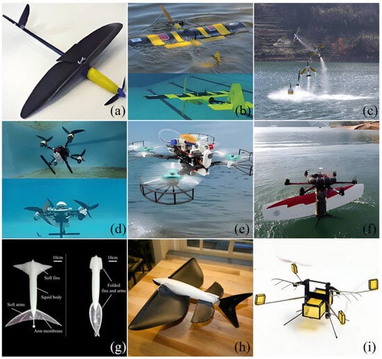
Figure 1.
Examples of multiple UAUV prototype models. (a) “AquaMAV”; (b) “Eagle Ray”; (c) “Longbow Ⅱ”; (d) “TJ-Flying Fish”; (e) Beihang University’s HAAV; (f) Shanghai Jiao Tong University’s “Nezha III”; (g) soft-bodied “squid-like” prototype; (h) “flying fish”; (i) Harvard University’s micro-robot “RoboBee”.
For UAUVs, the most challenging aspect involves the cross-media transition process during water exit and entry. The motion of an object across the air–water interface induces complex multiphase flow phenomena [32,33]. Advances in computational fluid dynamics (CFD) and substantial increases in computational power have enabled the numerical simulation of three-dimensional water-entry and water-exit problems. Consequently, the hydrodynamic analysis of UAUVs can benefit from established numerical methodologies developed for studying water-exit dynamics in other three-dimensional contexts. The water entry of hemispheres and cones was investigated by Wang et al. [34] using an Arbitrary Lagrangian–Eulerian (ALE) algorithm. A numerical procedure based on the finite volume method (FVM) was introduced by Jiang et al. [35] using the commercial software ANSYS Fluent to study the transient behavior of a super-cavitating flow past a cylindrical projectile crossing the air–water interface. The open-source FVM package OpenFOAM was utilized by Ma et al. [36] to simulate the large-amplitude motions of structures impacting water waves. The water entry of vertical and inclined cylinders was numerically studied by Derakhshanian et al. [37]. They demonstrated that the ALE algorithm in ABAQUS could reliably solve the associated fluid–structure interaction problems and accurately predict impact forces and moments, even under conditions of high entry velocity and large entry angle. A constrained interpolation profile (CIP)-based finite difference method was developed by Wen et al. [38] to address three-dimensional water entry problems, which involved capturing breaking free surfaces and air bubbles through a parallel algorithm and an interface-capturing scheme. A meshless method combining the adaptive particle refinement (APR) and smoothed particle hydrodynamics (SPH) methods was presented by Sun et al. [39] for simulating the water entry of two-dimensional and three-dimensional cylinders. These numerical approaches have also been employed to elucidate the sinking characteristics and underlying mechanisms of rigid cylinders in a surrounding fluid. The two-dimensional motion of a freely settling or rising submerged circular cylinder in an infinite fluid at a low Reynolds number (Re < 188) was numerically investigated by Namkoong et al. [40]. Computational fluid dynamics (CFD) was applied by Madjid et al. [41] to resolve the drag characteristics and secondary motions of large-sized cylinders falling in a quiescent fluid at moderate Reynolds numbers.
While there is a diverse range of structural designs for hybrid aerial–underwater vehicles, each is associated with specific limitations. To overcome these constraints, a novel structural design has been developed, innovatively proposed, and established as the research object in this study. A numerical methodology has been established to conduct a quantitative analysis of the hydrodynamic characteristics during the cross-medium process, thereby identifying the optimal operational state of the UAUV. Subsequently, the influences of velocity and entry angle on the operational characteristics have been compared through an analysis of the vortex dynamics illustrated by vector diagrams. The remainder of this paper is organized as follows. Section 2 introduces the internal structure and operational states of the proposed UAUV and explains the simplified model utilized for the computational process. The mathematical formulations for the computational fluid dynamics (CFD) analysis are detailed in Section 3. The configuration and verification of the computational model within the commercial CFD software STAR-CCM+ are described in Section 4. The numerical results and a detailed analysis of the cross-medium process are presented in Section 5. Finally, the conclusions drawn from this study are summarized in Section 6. A novel structure for UAUVs is introduced in this study, establishing a design direction distinct from conventional models. The feasibility of this structure has been verified through detailed simulation analysis. This exploration contributes to enriching the configuration framework for cross-media platforms while providing a theoretical foundation and a practical solution for the optimized design of subsequent high-performance vehicles.
2. Research Model
2.1. Structural Design
The subject of this investigation is a hybrid aerial–underwater vehicle (UAUV) that was independently designed and manufactured. A schematic of its geometric model is presented in Figure 2, and the detailed characteristics of the research model are presented in Table 1. It should be noted that the weight of UAUV is equal to the buoyancy. The UAUV comprises several key subsystems: the main airframe, a propulsion system, a vector steering system, a flight control and energy system, a center of gravity adjustment, and a buoyancy regulation system. The primary airframe features a cylindrical morphology to minimize hydrodynamic and aerodynamic drag during water entry and exit. To facilitate attitude control, the center of gravity adjustment and buoyancy regulation systems are positioned proximally within the central portion of the airframe. This arrangement ensures that the centers of buoyancy and gravity are aligned along the same vertical axis. The propulsion system is mounted atop the vehicle to provide thrust for both aerial flight and underwater locomotion. The vector steering system is actuated by multiple servo motors, enabling multi-degree-of-freedom propulsion. The flight control and energy system, which constitutes a relatively heavy subsystem, is installed at the base of the airframe to lower the center of gravity and enhance stability.
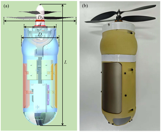
Figure 2.
A schematic of a geometric model. (a) Physical model; (b) Physical device.

Table 1.
Detailed characteristics of the research model.
The internal structure of UAUV mainly consists of five parts. The design principles and specific schemes of each system are shown in Figure 3.
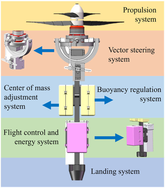
Figure 3.
Schematic diagram of the internal structure of UAUV.
- (1)
- Propulsion system
An integrated motor compartment has been adopted for the propulsion system, which incorporates two traditionally separate brushless motors into a single modular, coaxial drive unit. These two counter-rotating motors have been connected to independent inner and outer transmission shafts. The opposite ends of these shafts are coupled to two pairs of rotors, thereby enabling the upper and lower rotor pairs to spin in opposite directions. This coaxial dual-rotor assembly is mounted atop the fuselage, where it simultaneously generates thrust and counter-torque. In comparison to traditional helicopter or rotary-wing layouts, this configuration offers a significantly more compact form factor, reducing its circumferential footprint. Yaw control is achieved by utilizing the counter-torque vector through differential speed adjustments of the upper and lower rotors. This capability confers excellent maneuverability and motion performance upon the UAUV across a diverse range of environments and mission profiles.
- (2)
- Vector steering system
An innovative dual servo-actuated ball hinge-linkage transmission mechanism has been developed for thrust vector control. In this mechanism, ball hinges serve as pivotal joints for motion conversion. Planar motion inputs from two servo motors are transformed into spatial vector thrust via an asymmetric linkage assembly. The two servo-driven linkage mechanisms facilitate independent control over the pitch and roll axes of the dual-rotor propulsion system. Consequently, vector-based steering maneuvers are achieved by generating a relative angular displacement between the coaxial drive module and the fuselage.
- (3)
- Flight control and energy system
The avionics and flight control systems have been centrally integrated onto the underside of the fuselage. Furthermore, the battery pack has been positioned at the lowest point to deliberately lower the center of gravity. This configuration has been implemented to optimize the overall weight distribution, thereby enhancing vehicle stability during the critical water-entry and water-exit phases.
- (4)
- Center of mass adjustment and buoyancy regulation system
The center of gravity and buoyancy adjustment system has been designed to achieve dynamic control through the coordinated operation of centrally located retractable weights and a micro water pump. The relative position of the center of buoyancy and center of gravity is precisely regulated by the axial movement of these weights in conjunction with the intake or discharge of water from a dedicated compartment. During underwater navigation, the retraction of the weights lowers the center of gravity below the center of buoyancy. The resulting restoring moment induces a pitch rotation that stabilizes the vehicle in a horizontal attitude. For aerial flight, the weights are extended and the water tank is emptied. This raises the center of gravity until it is nearly coincident with the center of buoyancy, thereby ensuring flight stability. Furthermore, during the medium-transition process, the position of the weights and the resultant buoyancy distribution can be adjusted in real time. This enables a smooth pitch attitude transition by leveraging the coupled effects of hydrodynamic forces and gravitational moments. The core principle of this system lies in the active management of the relative center of buoyancy–center of gravity position, integrated with buoyancy control, to achieve self-stabilizing nonlinear regulation in a dual-medium environment.
- (5)
- Landing system
A four-legged landing gear assembly has been incorporated to provide impact buffering during landing events. This system, which consists of a conical central base and four adjustable support legs, has been designed to overcome the unidirectional load limitations inherent to traditional rigid frameworks. Furthermore, this configuration ensures environmental adaptability, dynamic stability, and durability during cross-media operations, while simultaneously maintaining a compact structural profile.
2.2. Working Conditions
The working conditions of the UAUV, as illustrated in Figure 4, comprise twelve distinct scenarios. The transition between each mode requires efficient coordination among its internal systems, as detailed below:
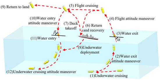
Figure 4.
Schematic diagram of different working conditions.
(1) Underwater cruising: Propulsion has been supplied by the propulsion system to maintain cruising status. The vector steering system has been employed to adjust the heading direction. The flight control and energy system has provided continuous power and ensured operational functionality. The center of mass adjustment and buoyancy regulation systems have been coordinated to stabilize the vehicle’s attitude by modulating the center of gravity and buoyancy force.
(2) Water-exit attitude maneuver: The vector steering system has been activated to alter the vehicle’s attitude. The center of mass adjustment and buoyancy regulation systems have been regulated concurrently to prepare an optimal posture for water exit. Throughout this process, the flight control and energy system has delivered precise control and power support to ensure adjustment accuracy.
(3) Water exit: The propulsion system has continuously provided thrust for ascent. The vector steering system has assisted in maintaining direction during emergence. The center of mass and buoyancy regulation systems have been fine-tuned to facilitate a successful exit. The flight control and energy system has guaranteed control and energy throughout the entire process.
(4) Flight attitude maneuver: The flight control and energy system has taken the leading role in aerial maneuvering. The vector steering system has adjusted the aerial attitude, while the center of mass adjustment system has stabilized the vehicle by regulating its center of gravity, preparing it for subsequent aerial operations.
(5) Flight cruising: The propulsion system has generated thrust for aerial travel. The flight control and energy system has managed flight control and ensured energy supply. The vector steering system has aided in course adjustment, and the center of mass adjustment system has maintained stability to ensure smooth cruising.
(6) Return and recovery: The propulsion system has provided thrust for return. The flight control and energy system has handled navigation and power management during the return. The vector steering system has steered the return course, and the center of mass and buoyancy regulation systems have prepared the vehicle’s attitude for potential surface or underwater recovery.
(7) Deck takeoff: The propulsion system has delivered take-off thrust for launch from the deck. The flight control and energy system has secured control and energy for the take-off process. The vector steering system has assisted in directing attitude at launch, and the center of mass adjustment system has stabilized the vehicle to ensure a successful take-off.
(8) Underwater deployment: The propulsion system has driven the vehicle to the deployment zone. The flight control and energy system has overseen control and energy management during deployment. The vector steering system has adjusted the heading, and the center of mass and buoyancy regulation systems have modulated attitude and buoyancy to ensure precise deployment.
(9) Return to land: The propulsion system has powered the return to land. The flight control and energy system has safeguarded control and energy supply during the return. The vector steering system has corrected the return trajectory, and the center of mass adjustment system has sustained stability for a successful landing.
(10) Water-entry attitude maneuver: The vector steering system has oriented the vehicle for water entry. The center of mass and buoyancy regulation systems have been adjusted in concert with the flight control and energy system to achieve the desired pre-entry attitude.
(11) Water entry: The propulsion system has impelled the vehicle toward and into the water. The flight control and energy system has administered control and energy management during entry. The vector steering system has guided the direction of entry, and the center of mass and buoyancy regulation systems have managed attitude and buoyancy for a successful immersion.
(12) Underwater cruising attitude maneuver: The propulsion system has sustained underwater propulsion. The flight control and energy system has governed control and energy for attitude recovery. The vector steering system has realigned the vehicle, and the center of mass and buoyancy regulation systems have been calibrated to restore a stable underwater cruising attitude.
2.3. Analysis Framework
The water-entry and water-exit process represents one of the most complex and critical phases in the mission profile of a hybrid aerial-undersea vehicle (UAUV). The stability of this transient process and the structural integrity of the vehicle are paramount to mission success. The water-entry angle is a critical parameter governing the vehicle’s interaction with the air–water interface. An excessively shallow angle can induce planing instability, leading to severe pitch and roll oscillations; conversely, an excessively steep angle causes intense water impact (or slamming), generating extreme instantaneous loads. The vehicle’s velocity at the moment of impact directly dictates the kinetic energy involved. A high-impact velocity amplifies these adverse effects, potentially leading to a loss of attitude control (e.g., bouncing or tumbling) and posing a severe risk of structural overload. This can result in permanent deformation or damage to the hull, internal components, and support structures. Therefore, accurately quantifying the influence of water-entry angle and velocity on the hydrodynamic characteristics—such as impact load, wetted area variation, cavity dynamics, and center of pressure drift—is a fundamental prerequisite for predicting motion stability, assessing structural loads and fatigue life, and ultimately achieving a controllable and reliable cross-medium vehicle design. Consequently, this study investigates the influence mechanisms of water-entry angle and velocity on the hydrodynamic performance of UAUVs through systematic numerical simulation and theoretical analysis. The findings aim to provide a critical theoretical foundation and empirical data for optimizing hull design and control strategies.
To simulate the aforementioned complex transient process using CFD, the geometric model has been reasonably simplified. The main body has been simplified to a fundamental cylindrical profile, while the key wing sections have been retained. The simplified model is shown in Figure 5. Fx and Fz respectively represent the lateral force and the axial force. Vx and Vz respectively represent the lateral velocity and axial velocity. wy is the angular velocity and My is the hydrodynamic moment. θ is used to represent the attack angle.
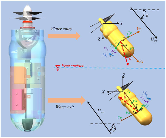
Figure 5.
Simplified model of UAUV.
This simplification strategy has been adopted based on two primary considerations:
First, to capture the core physical phenomena. The paramount hydrodynamic characteristics during water-entry and water-exit—such as cavity generation and collapse, impact load distribution and magnitude, and free-surface deformation and fragmentation—are predominantly governed by the macroscopic body shape and the lift-generating effect of the wings. Consequently, internal complexities such as vectoring steering mechanisms, servos, and battery packs have been omitted from the model. Although these components can introduce local flow complexities, their influence on the global flow dynamics and macroscopic loads is considered a second-order effect. Their omission significantly reduces the computational mesh count, mitigates numerical singularities, and enhances simulation efficiency and stability.
Second, to ensure the clarity of the underlying physical mechanisms. This study is designed to isolate and quantify the influence of the two core variables—water-entry angle and velocity—on the fundamental hydrodynamic characteristics. The simplified geometry effectively avoids confounding interference from minor geometric features, thereby enabling a clearer revelation of the intrinsic relationship between water-entry kinematics (angle and velocity) and the dynamic response. This approach facilitates the derivation of more generalizable and instructive conclusions, thereby laying a robust foundation for subsequent detailed engineering design and optimization.
3. Mathematical Formulation
A viscous computational fluid dynamics (CFD) approach was employed to investigate the hydrodynamic characteristics and underlying flow mechanisms during both water-entry and water-exit phases of the UAUV. The numerical framework encompassed the governing equations, turbulence modeling, and solver configurations.
3.1. Governing Equations
All fluid flows adhere to the laws of conservation of mass, momentum, and energy. The computational framework has been implemented for three-dimensional, implicitly unsteady, two-phase flow comprising water and air. The flow field temperature was assumed constant in this work; heat exchange and thermal energy variations were neglected. The governing continuity and momentum equations have been adopted [42].
where ρm and μm are the mixture density and the mixture dynamic viscosity, respectively. Their expressions are as follows:
where the subscripts w and a denote the water and air phases, respectively. P is the pressure and gi are the components of gravitational acceleration. μt is the turbulent viscosity. ui and uj are the local fluid mass velocity components. μ is the kinetic viscosity coefficient.
3.2. Turbulence Model
The closure of the Reynolds-averaged Navier–Stokes (RANS) equations necessitates the use of turbulence models. Among the widely adopted two-equation models in engineering practice are the standard k-ε, RNG k-ε, realizable k-ε, standard k-ω, and Shear Stress Transport (SST) k-ω models. For the present study, the SST k-ω model was selected. This model, proposed by Menter et al. [43], has been extensively validated in industrial applications. Its hybrid formulation blends the respective advantages of the k-ω and k-ε models through a blending function. It preserves the accuracy and stability of the k-ω formulation in near-wall regions while maintaining the computational economy of the k-ε model in free-stream regions. The SST k-ω model can be used as a flow application without extra damping functions and is able to capture flow separation. The governing transport equations for turbulent kinetic energy (k) and specific dissipation rate (ω) were defined as follows:
where Γk and Γω are the diffusion rates of k and ω, respectively; Gk and Gω are turbulent kinetic energy production terms; Yk and Yω represent dissipative sources; and Sk and Sω are source terms.
The numerical simulations were conducted employing the commercial CFD software STAR-CCM+. The SIMPLEC algorithm was employed for pressure–velocity coupling to enhance convergence and computational stability in transient simulations. The finite volume method (FVM) was utilized to discretize the governing equations. Pressure interpolation was handled with the PRESTO scheme. A second-order upwind scheme was adopted for the convection terms, while a second-order central difference scheme was applied to the diffusion terms. The transient term was discretized using a first-order implicit method, and the gradients were computed based on the least squares cell-based method. Finally, the Geo-Reconstruct scheme was used to resolve the volume fraction transport equation. Other related settings can be referred to in Zhang et al. [44].
3.3. Volume-of-Fluid Multiphase Model
The flow dynamics generated by the UAUV’s inflow and outflow constitute a typical gas–liquid two-phase flow problem. To capture the interfacial characteristics, the algebraic volume of fluid (VOF) method with an artificial compression term was employed. This method offers superior mass conservation properties. The VOF model was introduced to accurately capture free surface dynamics; its core mechanism involves interface tracking through the solution of a volume fraction transport equation. Furthermore, the HRIC (High Resolution Interface Capture) technology was utilized to enhance the prediction accuracy of free surface changes. The phase volume fraction αi was defined as:
where V denotes the volume of a grid cell, and Vᵢ represents the volume occupied by phase i within that cell. For a system of N phases, the sum of all phase volume fractions within any given cell must satisfy the following constraint:
Combining Equations (7) and (8), the governing equation for the water volume fraction can be described as follows:
where ui represents the velocity vector. The volume fractions of water and air are denoted by αw(x, y, z, t) and αg(x, y, z, t), respectively. The value of αw in any computational cell defines its phase content as follows:
- A value of αw = 1 indicates a cell completely filled with water;
- αw = 0 signifies a cell containing exclusively air;
- Any intermediate value (0 < αw < 1) corresponds to a cell containing a gas–liquid interface.
3.4. 6-DOF Motion Solver
The motion posture of the UAUV varies significantly with its velocity under different operating conditions. Consequently, artificially imposed constraints on pitch and trim cannot accurately represent the actual motion of the hybrid aerial underwater vehicle. To improve the numerical rigor and predictive accuracy, the Dynamic Fluid–Body Interaction (DFBI) model in STAR-CCM+ was employed. This model simulates the coupled fluid–structure interaction and solves the six-degree-of-freedom (6-DoF) rigid body motion equations.
The origin of the reference coordinate system was defined at the center of mass of the UAUV. The governing equations for the 6-DoF motion are as follows:
where p, q and r are angular velocity components, and Ii (i = x, y, z) is the component of the moment of inertia.
The hydrodynamic behavior of the UAUV is analogous to an unmanned aerial vehicle (UAV) in the air and an unmanned underwater vehicle (UUV) in water. This study focuses on the water-entry and water-exit phases of the UAUV, with particular emphasis on the rapidity of the transition and its implications for hydrodynamic resistance and propulsive efficiency. The key parameters investigated include the water-entry/exit angle, velocity, mass properties, center of gravity coordinates, and moment of inertia. Accordingly, within the DFBI framework, motions were permitted along the body-fixed x-axis and z-axis, as well as rotation about the y-axis. Motions along the y-axis and rotations about the x-axis and z-axis were constrained. This configuration established a numerically efficient framework specifically for simulating the water-to-air cross-domain transition.
4. Numerical Settings and Verification
The STAR-CCM+ (version 202402) was used for numerical simulation in this work. Specific numerical methods are described below.
4.1. Computational Domain and Grid Division
The computational domain and boundary conditions for the numerical simulation of the UAUV flow field with a free surface are shown in Figure 6. Given the structural complexity of the UAUV, the computational domain was partitioned into two distinct domains: an overset region encompassing the vehicle and its moving components, and a stationary far-field region containing the surrounding flow. The computational domain for the water-entry simulation is illustrated in Figure 6a. All relevant dimensions are non-dimensionalized by the diameter (D) of UAUV. The far-field domain is a cuboid domain with dimensions of 20D × 30D × 23D (X × Y × Z), replicating the dimensions of the experimental water tank. The distance from the undisturbed free surface to the domain bottom is 5D. The top boundary was set as a velocity inlet, while the other five boundaries were defined as no-slip walls. The overset region is cylindrical with a diameter of 5D and envelops the main body of the UAUV. The UAUV surface was modeled as a no-slip wall. The overset interface was defined to facilitate motion and data exchange between the static far-field and moving overset grids. The orientation of the overset region’s motion was prescribed according to the water-entry angle β. The computational domain for water-exit, shown in Figure 6b, shares an identical far-field setup with the water-entry case. The distance from the free surface to the bottom is 12D. The motion direction of the overset region was similarly prescribed by the water-exit angle β. The initial speed at which the UAUV enters water from the air is defined as Uaw, and the initial speed at which it enters the air from water is defined as Uwa.
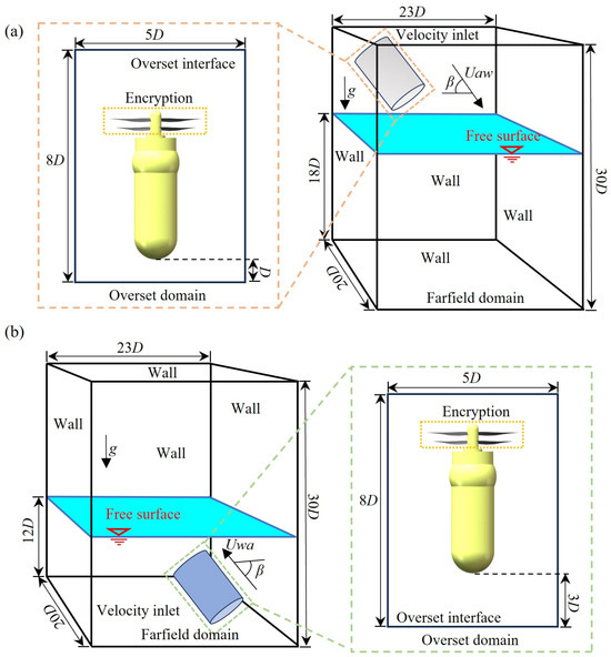
Figure 6.
Diagram of computational domain and boundary conditions. (a) water-entry process; (b) water-exit process.
The accuracy of complex flow field simulations is highly dependent on grid quality. To ensure accurate data transfer between the overset and far-field domains, their grid sizes were maintained at a comparable scale. The built-in meshing tools in STAR-CCM+ were utilized to discretize the computational domain. To enhance the resolution of non-uniform flow features and the free surface interface, mesh refinement was applied to the no-slip walls and in critical regions, including the free surface, motion curve and propulsion system. Anisotropic refinement was achieved using a trim mesh technique. A representative grid configuration for the β = 50° condition is illustrated in Figure 7. Simulations for other water-entry and water-exit angles were conducted by rotating the overset domain accordingly. Furthermore, prismatic boundary layers were generated on the UAUV surfaces to resolve the near-wall flow and satisfy the resolution requirements of the SST k-ω turbulence model. The wall resolution was controlled by adjusting the thickness of the first grid layer to achieve a target y+ value suitable for the selected turbulence model. The reference equation is as follows:
where y represents the distance from the first grid cell centroid to the wall, and τw denotes the wall shear stress. A robust, automatic prismatic layer mesher was employed to resolve the boundary layer and facilitate the use of an all-y+ wall treatment. This hybrid approach was selected to accommodate complex flow geometries and velocity gradients where maintaining a purely low or high y+ value is challenging. It automatically applies a low-Reynolds-number treatment (resolving the viscous sublayer) on fine meshes and switches to a wall-function-based treatment on coarser meshes.
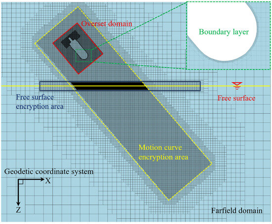
Figure 7.
Meshing of the computational domain.
Previous studies have demonstrated that maintaining a y+ value between 30 and 300 yields optimal accuracy for resistance predictions when employing the SST k-ω model for surface craft [45]. Accordingly, the first-layer grid thickness was set to 2.1 × 10⁻⁴ m, and six prismatic layers with a growth rate of 1.2 were generated. This configuration ensured that the dimensionless wall distance y+ was predominantly maintained within the target range of 30–300 across most of the UAUV’s wetted surface during the simulations.
4.2. Verification of Grid Independence
The accuracy of numerical simulation’s results is highly dependent on the quality of the computational mesh. A grid independence study was conducted to eliminate the influence of mesh size on the solution. The verification condition selects β = 50 and a speed Uaw = 8 m/s. Five grid resolutions for the computational domain and the grid details for each resolution are shown in Table 2. The grids were uniformly refined based on a refinement ratio (rg), which was defined as a function of the total cell count. The reference equation is as follows:
where Nfine and Ncoarse indicate the total number of cells in the adjacent scale grids, while d represents the problem’s dimensionality (d = 3).

Table 2.
Parameters of the grids with different resolutions.
Figure 8 compares the lateral displacement (along the X-axis of the geodetic coordinate system) and vertical displacement (along the Z-axis of the geodetic coordinate system) predicted by the five grid resolutions. The data in the figure indicate that the positive direction of the axis is positive. The results show close agreement across all resolutions, with only minor numerical discrepancies observed. The solution demonstrates excellent monotonic convergence, with an overall error of less than 4% for the medium grid resolution compared to the finer. Based on this analysis, the medium-resolution grid was selected for all subsequent simulations of the UAUV’s water-entry and water-exit processes, offering an optimal balance between predictive accuracy and computational cost.
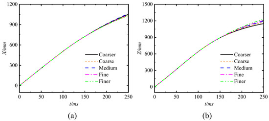
Figure 8.
Comparison of the displacement using five mesh resolutions. (a) Lateral displacement (along X-axis of the geodetic coordinate system); (b) Vertical displacement (along Z-axis of the geodetic coordinate system).
4.3. Validation of the Numerical Model
To validate the accuracy of the numerical model, the parameter variations during the sinking process of a negatively buoyant cylinder have been compared and analyzed, following the methodology and conditions described in Xiang et al. [42]. The cylinder dimensions were set to a diameter of 20 mm and a length of 100 mm. Following this strategy, the computational domain was created and discretized into three distinct mesh configurations with varying resolutions. These meshes were designated in order of increasing refinement as coarse (Nt = 1.652 × 10⁶), medium (Nt = 2.855 × 10⁶), and fine (Nt = 4.933 × 10⁶). “Nt” represents the total number of grids. The simulation results have been compared against the experimental data reported by Lyu et al. [46], specifically by plotting the temporal evolution of the lateral displacement (Y). A comparison of the results is presented in Figure 9. It is noteworthy that the water-entry process is defined as commencing from the initial contact between the cylinder and the water surface and concluding when the cylinder is completely submerged (i.e., it has traversed a vertical distance equal to its own diameter, at an entry angle β = 90°). The subsequent motion is referred to as the sinking process. To maintain consistency with Lyu et al. [46], the time t = 0 ms corresponds to the instant marking the end of the water-entry process and the commencement of the sinking process. As shown in Figure 9, the temporal trends of the lateral displacement predicted by all three mesh configurations exhibit substantial agreement with the experimental measurements. The discrepancy between the simulated and experimental results gradually diminishes with increasing mesh refinement. While a significant discrepancy is observed for the coarse mesh, the results obtained from the medium and fine meshes demonstrate minor differences and are in close agreement with each other. Considering computational economy, the medium mesh was selected for all subsequent simulations. This outcome confirms that the mesh strategy employed in this study ensures a reliable balance between computational cost and solution accuracy, demonstrating good convergence in both spatial and temporal resolution.
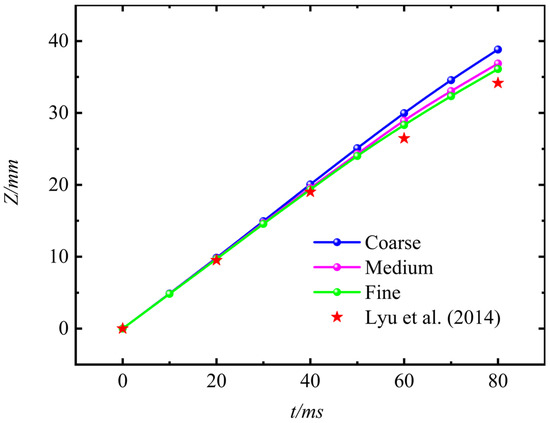
Figure 9.
Comparison of vertical displacement–time curve using different element sizes and time step during sinking process [46].
5. Analysis of the Process of the UAUV Entering Water from the Air
Unlike traditional underwater unmanned vehicles and airborne drones, UAUV involves cross-domain motion from water to air and vice versa. Due to the significant differences in density and dynamic viscosity coefficients between air and water, transient impact loads are generated during the cross-fluid medium motion of the object. This has a significant impact on its safe, efficient and stable cross-medium motion. Accurate prediction of the mechanical and kinematic characteristics of UAUV during cross-fluid motion, and obtaining the evolution mechanism of its mechanical characteristics by analyzing the flow field characteristics, are of great significance for the design of high-performance UAUVs. This section conducts a numerical simulation and analysis of the processes of water entering air and air entering water for UAUV from different angles and speeds. Considering the actual application scenarios of UAUV, the angles for water entering air and air entering water are set at 50°, 70°, and 90°, while the speed for air entering water is set at 1 m/s, 4 m/s, and 8 m/s, and the speed for water entering air is set at 4 m/s and 8 m/s.
5.1. The Influence of the Entry Angle on the UAUV’s Water-Entry Process
5.1.1. Motion Trajectory
Figure 10 shows the trajectory of the UAUV’s center of mass as it moves from the air into the water with different Uaw and different β. The dotted lines of different colors in the figure represent the trajectories of the center of mass of the UAUV as it enters the water from the air at different β. The solid dots of the same color on the dotted lines indicate the position of the center of mass of the UAUV when the nose just touches the water surface. As can be seen from the figure, when Uaw is small, when the aircraft enters the water at an oblique angle, the motion trajectory of the UAUV will fluctuate when entering the water at an oblique angle, and the amplitude of the fluctuation gradually increases as Uaw decreases. When Uaw is 8 m/s, when the UAUV moves from the air to the water with different β, its trajectory is almost always a straight line. This indicates that increasing the Uaw helps to improve the stability of the UAUV’s trajectory when moving from the air to the water. It is worth noting that when Uaw is 4 m/s, after the aircraft enters the water at an oblique angle, its trajectory will experience a slight downward curve followed by a slight upward rise. When Uaw is 1 m/s, when the UAUV enters the water at an oblique angle, its trajectory will experience multiple consecutive ascents and descents, and the overall movement will show unstable fluctuations.
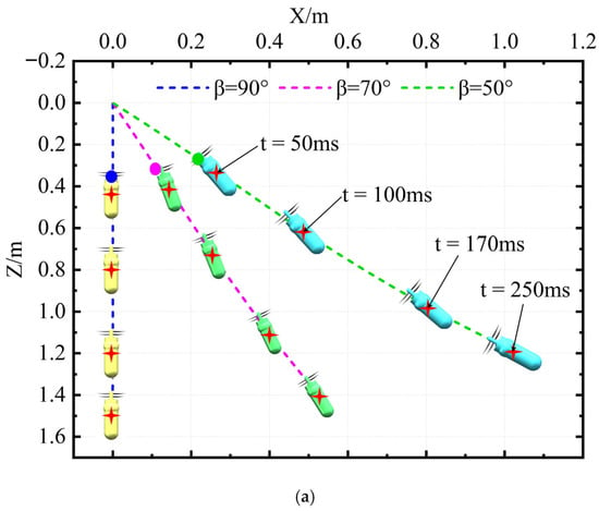
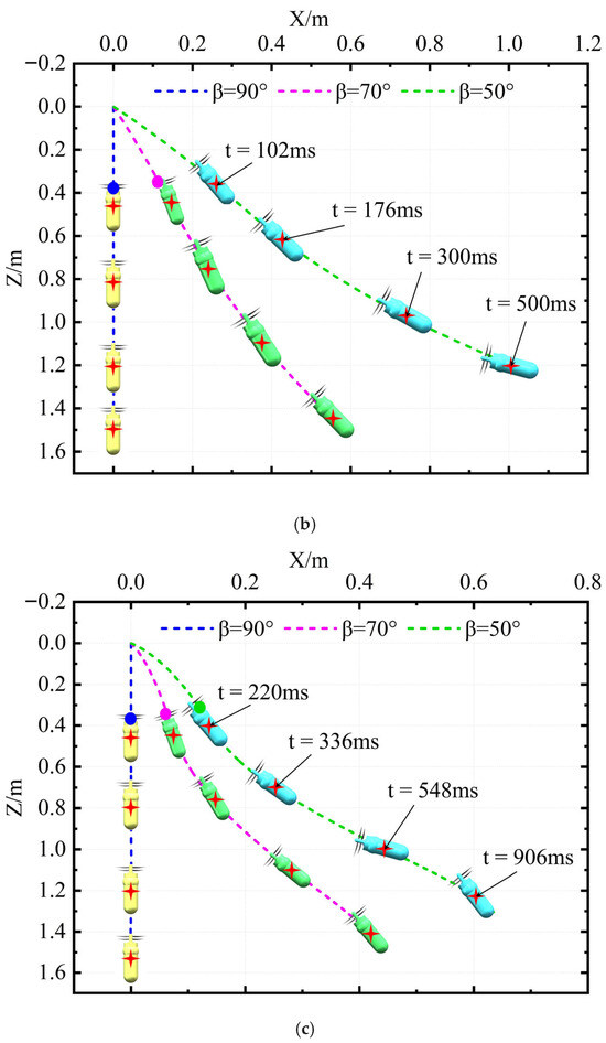
Figure 10.
The motion trajectory of the UAUV for air entering water: (a) Uaw = 8 m/s; (b) Uaw = 4 m/s; (c) Uaw = 1 m/s.
5.1.2. Attack Angle
Figure 11
shows the attack angle θ of the UAUV as it moves from the air into the water with different Uaw and different β. As can be seen from the figure, when the UAUV is perpendicular to the water surface and enters the water from the air, as the Uaw increases, θ will increase slightly and the rate of increase will also show an increasing trend. However, the overall increase in amplitude is still relatively small and has little impact on the water-entry process. When the UAUV enters the water at an inclined angle, at different Uaw, the θ shows a linearly increasing trend in the initial stage of the water-entry process, and the rate of increase increases as Uaw decreases. Interestingly, when the UAUV enters the water at an inclined angle, as Uaw decreases, θ increases to a certain value and then begins to decrease rapidly.

Figure 11.
The attack angle of the UAUV for air entering water: (a) Uaw = 8 m/s; (b) Uaw = 4 m/s; (c) Uaw = 1 m/s.
5.1.3. Motion Velocity
Figure 12 presents the curves of the axial velocity Vz and lateral velocity Vx of the UAUV in the body-fixed coordinate system. It can be seen that when Uaw is the same, the Vz of the UAUV all have the same changing trend, indicating that the influence of the entry angle on the changing trend of the Vz of UAUV can be ignored. Before entering the water, UAUV needs to fall a certain distance in the air. Due to the relatively small air resistance, during this process, Vz accelerates under the effect of gravity, and the Vz shows a linear increasing trend. After the UAUV touches the water surface, a slight oscillation occurs. When the Uaw is small, after the UAUV enters the water, Vz will increase slightly and then decrease rapidly. This is because the UAUV’s gravity is greater than the water’s buoyancy. Before the UAUV enters the water, the amplitudes of the Vx under different parameters all show a linearly increasing trend. When Uaw is relatively small, after the UAUV enters the water, the amplitude of the Vx shows a linearly decreasing trend and gradually approaches zero. As the Uaw increases, after the UAUV enters the water, the amplitude of Vx shows a slight decrease and then tends to a constant value. However, as the Uaw value continues to increase, the amplitude of Vx first decreases slightly and then gradually increases, indicating that the increase in Uaw has a significant impact on the lateral velocity of the UAUV.

Figure 12.
The motion velocity of the UAUV in the body-fixed coordinate system: (a) Uaw = 8 m/s; (b) Uaw = 4 m/s; (c) Uaw = 1 m/s.
5.1.4. Angular Velocity
The angular velocity ωy of the UAUV during the process of entering water from the air is shown in Figure 13. As can be seen from the figure, ωy is always equal to zero before the UAUV enters the water. When the UAUV enters the water perpendicularly to the water surface, ωy remains close to zero, indicating that the entry of the UAUV into the water is stable. As β decreases, that is, the angle between UAUV and the water surface gradually decreases, the rate at which ωy increases after UAUV enters the water gradually increases, and there is a sudden decrease after UAUV completely enters the water. Subsequently, UAUV continues to move in the water. When the value of Uaw was the same, regardless of the value of β, ωy always showed the same trend. When Uaw is small, ωy increases to its maximum value and then decreases rapidly. That is, the UAUV’s upward movement gradually decreases and then gradually increases in the negative direction, indicating that the UAUV starts to perform a downward movement. As Uaw increases, the UAUV always performs an upward movement after entering the water, and the speed of this upward movement increases rapidly with the increase of Uaw. This indicates that when the UAUV enters the water at an angle to the water surface, increasing Uaw can help the UAUV quickly passively transform from a tilted state to a horizontal state, which is beneficial for the UAUV to quickly change to a horizontal navigation state but not conducive to rapid diving.

Figure 13.
The angular velocity of the UAUV in the body-fixed coordinate system: (a) Uaw = 8 m/s; (b) Uaw = 4 m/s; (c) Uaw = 1 m/s.
5.1.5. Hydrodynamic Force
Figure 14 shows the variation process of the axial force Fz of the UAUV. From the figure, it can be seen that when the UAUV contacts the water surface, a transient high load will be generated in the opposite direction of its movement. The amplitude of this load is not much related to the angle of entering the water but is significantly affected by the speed of entering the water. Subsequently, the amplitude of Fz decreases rapidly. When Uaw is the same, Fz shows a similar trend of change under different β. When UAUV moves in the air without contacting the water surface, Fz is generated by the gravity of UAUV. When UAUV contacts the water surface, Fz undergoes a significant jump increase in the negative z-axis direction, followed by a significant jump decrease. Then, as UAUV continues to enter the water, Fz first increases slowly in the negative z-axis direction and then increases sharply. After UAUV completely enters the water, the amplitude of the Fz gradually decreases to zero.

Figure 14.
The axis force of the UAUV in the body-fixed coordinate system: (a) Uaw = 8 m/s; (b) Uaw = 4 m/s; (c) Uaw = 1 m/s.
Figure 15 presents the time-history curve of the UAUV’s lateral force Fx. From the figure, it can be seen that the trend of Fx changes similarly under the same Uaw. After the UAUV enters the water, it all increases in the negative direction. As Uaw increases, Fx will tend to a non-zero value after a period of time and will not be affected by β. When Uaw is small, Fx will tend to zero.

Figure 15.
The lateral force of the UAUV in the body-fixed coordinate system: (a) Uaw = 8 m/s; (b) Uaw = 4 m/s; (c) Uaw = 1 m/s.
5.1.6. Hydrodynamic Moment
The hydrodynamic moment My of the UAUV during the water-entry process is shown in
Figure 16. As can be seen from the figure, during the process of the UAUV transitioning from air to water, there will be frequent oscillations. However, the average value of the oscillations is greater than zero, causing the aircraft to undergo an upward movement. After the aircraft completely submerges in water, when Uaw is small, My will change slowly in the negative direction. As Uaw increases, My will change slowly in the positive direction.

Figure 16.
The hydrodynamic torque of the UAUV in the body-fixed coordinate system: (a) Uaw = 8 m/s; (b) Uaw = 4 m/s; (c) Uaw = 1 m/s.
5.2. The Influence of the Entry Speed on the UAUV’s Water-Entry Process
Since the UAUV enters water at an angle perpendicular to the water surface, its trajectory is not affected by the entry speed and remains approximately a vertical line; therefore, we only analyze the situation where the UAUV enters water at an angle to the water surface.
5.2.1. Motion Trajectory
Figure 17 shows the trajectories of the UAUV as it enters water from the air at a constant β at different Uaw. As can be seen from the figure, when β is constant, as Uaw increases, the trajectory of the UAUV’s entry into the water gradually changes from multiple consecutive fluctuations to a single fluctuation and eventually approaches a straight line. When Uaw is greater than 4 m/s, the motion trajectory of the UAUV gradually becomes stable.
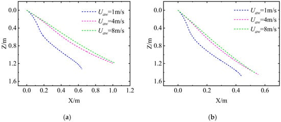
Figure 17.
The motion trajectory of the UAUV for air entering water: (a) β = 50°; (b) β = 70°.
5.2.2. Attack Angle
Figure 18 shows the attack angle θ of the UAUV as it moves from the air into the water with different Uaw. As can be seen from the figure, when Uaw is small, the θ increases from zero to a maximum value and then decreases to negative. As the Uaw increases, θ keeps increasing and the rate of increase gradually increases. The variation trend of θ indicates that when the UAUV enters the water at an angle to the water surface, when Uaw is small, the entry process of the UAUV is unstable. As Uaw increases, the θ keeps increasing, that is, it keeps performing an upward movement.
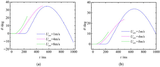
Figure 18.
The attack angle of the UAUV for air entering water: (a) β = 50°; (b) β = 70°.
5.2.3. Motion Velocity
Figure 19 presents the curves of the axial velocity Vz and lateral velocity Vx of the UAUV in the body-fixed coordinate system. As can be seen from the figure, when β is constant, the axial velocity Vz of the UAUV before entering the water shows a linearly increasing trend. This is due to the effect of its own gravity. Although the UAUV entered the water at the same height, the different initial velocities Uaw resulted in different times for the UAUV to enter the water, which in turn affected the time during which Vz increased linearly. When UAUV enters the water, Vz decreases rapidly in a nonlinear manner and eventually stabilizes at a certain value. As Uaw increases, the rate of decrease becomes even faster. Interestingly, the trend of Vz over time shows similarities. Especially when β is 50°, the variation curves of Vz under different Uaw values almost overlap, indicating that when β is the same, the trend of the axial velocity of the UAUV is similar. As can be seen from the figure, the smaller the Uaw is, the faster the Vx decreases after the UAUV enters the water. When Uaw is 8 m/s, Vx still shows an increasing trend after the UAUV enters the water.
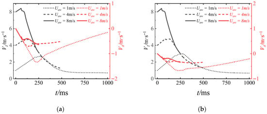
Figure 19.
The motion velocity of the UAUV in the body-fixed coordinate system: (a) β = 50°; (b) β = 70°.
5.2.4. Angular Velocity
The angular velocity ωy of the UAUV during the process of entering water from the air is shown in Figure 20. As can be seen from the figure, ωy is always equal to zero before the UAUV enters the water. When the UAUV touches the water surface, ωy increases rapidly, indicating that the UAUV is performing an upward movement. After the UAUV completely enters the water, there will be small fluctuations in ωy, and subsequently, the trend of ωy will be significantly influenced by Uaw. As can be seen from the figure, when Uaw is less than or equal to 4 m/s, ωy first increases to its maximum value and then undergoes a small jump, followed by a rapid decrease. However, when Uaw is 8 m/s, ωy increases to its maximum value and then undergoes a small jump before continuing to increase. The trend of ωy indicates that when UAUV is inclined towards the water surface and enters the water, the influence of Uaw on the increasing rate of ωy is not significant, but it has a significant impact on the decreasing trend of ωy after it reaches its maximum value. That is, the larger Uaw is, the more gradual the decreasing trend of ωy will be.
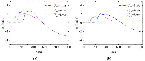
Figure 20.
The angular velocity of the UAUV in the body-fixed coordinate system: (a) β = 50°; (b) β = 70°.
It is noteworthy that if the angular velocity around the y-axis (ωy) is not zero when the UAUV enters the water (i.e., there is unexpected rotation), it will have a significant negative impact on the water-entry stability and subsequent motion of the UAUV: First, ωy ≠ 0 will disrupt the stable variation trend of the attack angle θ (refer to Section 5.1.2), causing θ to deviate from the design threshold. This further imbalances the coupling relationship between the axial velocity Vz and the lateral velocity Vx (Section 5.1.3), changing the trajectory from a gentle curve to irregular undulations. Especially when Uaw is small (1~4 m/s), this fluctuation will overlap with the trajectory oscillation caused by velocity, intensifying the risk of attitude loss. Second, non-zero ωy will lead to asymmetric distribution of hydrodynamic loads on the fuselage surface, increasing the fluctuation amplitude of the axial force Fz in the negative z-axis direction and causing high-frequency jumps in the lateral force Fx (Section 5.1.5). Furthermore, it will destroy the balance of the hydrodynamic moment My, triggering a vicious cycle of “rotation-moment imbalance” and imposing higher requirements on the structural strength of the fuselage and the differential speed adjustment capability of the propulsion system.
5.2.5. Hydrodynamic Force
Figure 21 shows the variation process of the axial force Fz of the UAUV. From the figure, it can be seen that when the UAUV contacts the water surface, a transient high load will be generated in the opposite direction of its movement. The amplitude of this load is significantly affected by the speed of entering the water. As Uaw decreased, the amplitude of Fz decreased to zero and then continued to increase in the direction of the UAUV’s movement, thereby generating a propulsive force that would cause the UAUV to enter the water. During the process of the UAUV entering the water, in addition to being subjected to the transient impact loads generated by the water, it is also affected by the net buoyancy force produced by the water. When Uaw is large, the UAUV enters the water more quickly. The net buoyancy force acting on it can quickly counteract its gravity. Therefore, when Uaw is small, the buoyancy force acting on the UAUV cannot quickly counteract its gravity, so the Fz will increase in the direction of entering the water. As time progresses, the UAUV completely submerges in the water. Due to the influence of the axial velocity, in addition to the net buoyancy generated by the water, the UAUV also receives the hydrodynamic force exerted by the fluid. This force is opposite to the direction of motion, so Fz will rapidly increase in the negative direction and then slowly decrease after reaching its maximum value.
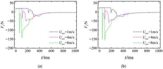
Figure 21.
The axis force of the UAUV in the body-fixed coordinate system: (a) β = 50°; (b) β = 70°.
Figure 22 presents the time–history curve of the UAUV’s lateral force Fx. As can be seen from the figure, the trend of Fx is similar to that of Fz. After the UAUV touches the water surface, there is a significant jump in the value of Fx in the negative direction of the x-axis. However, unlike Fz, Fx will exhibit multiple rapid amplitude jumps again. But the overall trend of the amplitude is constantly increasing and eventually slowly decreases to zero. As Uaw increases, the degree of amplitude jump of Fx keeps increasing, and the overall change trend is similar.
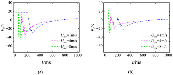
Figure 22.
The lateral force of the UAUV in the body-fixed coordinate system: (a) Uaw = 8 m/s; (b) Uaw = 4 m/s.
5.2.6. Hydrodynamic Moment
The hydrodynamic moment My of the UAUV during the water-entry process is shown in
Figure 23. As can be seen from the figure, during the process of the UAUV entry into the water, My will exhibit high-frequency and large-amplitude oscillations. As the value of Uaw decreases, the amplitude of the oscillations of My gradually decreases and the oscillation period gradually increases. After the UAUV is completely submerged, My gradually approaches zero.
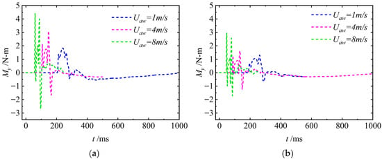
Figure 23.
The hydrodynamic torque of the UAUV in the body-fixed coordinate system: (a) Uaw = 8 m/s; (b) Uaw = 4 m/s.
5.3. Cavity Evolution and Jet Formation
The cavity evolutions at water-entry angles of β = 50°, 70°, and 90° are selected as examples to illustrate the typical characteristics of cavity formation with the UAUV motion. Figure 24 and Figure 25 show the cavity evolution and two-phase diagram with these entry angles during water entry with Uaw = 8 m/s. For ease of analysis, we define that when looking forward along the spiral, the left-hand side is the left side of the UAUV, and the right-hand side is the right side of the UAUV.
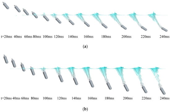
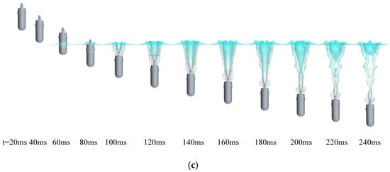
Figure 24.
Cavity evolution of the water entry at different water-entry angles: (a) β = 50°; (b) β = 70°; (c) β = 90°.
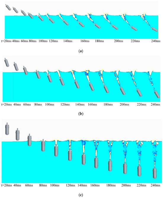
Figure 25.
The two-dimensional two-phase diagram of water and air during the water-entry process of the UAUV: (a) β = 50°; (b) β = 70°; (c) β = 90°.
As can be seen from Figure 24a and Figure 25a, when the UAUV enters the water at an angle, the right side of the UAUV’s head is the first to come into contact with the water surface. Under the effect of high pressure, the water surface spreads out and splashes in all directions, creating an asymmetric cavity at the front of the UAUV, with a smaller cavity in the left backflow region and a larger cavity in the right incident flow region. As the UAUV continued to submerge, the cavities did not form at the front of the UAUV but remained connected to the rear of the UAUV. They also created two layers of cavities on the outer surface of the UAUV and on the propeller shaft, with these nested cavities gradually being elongated and expanded under the UAUV’s movement, reaching their maximum size at t = 140 ms. Subsequently, under the pressure of the water, the cavities connected to the UAUV’s tail were rapidly compressed and collapsed, separating from the UAUV’s tail. This caused the rear of the UAUV to lose the accompanying buoyancy from the cavities rapidly, disrupting the balance of the fluid hydrodynamic and static forces acting on the UAUV, and thus resulting in the UAUV rotating counterclockwise.
When water-entry angle β = 70° in Figure 24b and Figure 25b increases, since the axial speed of the UAUV is the same (i.e., the entry speed Uaw), the vertical velocity component of the UAUV will also increase. The volume of the cavities generated on the UAUV’s outer surface and the propeller shaft will also become larger. Eventually, after 160 ms, they begin to contract and slowly break under the action of the static pressure of the fluid. This results in the continuous action of the accompanying buoyancy generated by the cavities on the UAUV lasting longer. Therefore, the counter-clockwise rotation angle of the UAUV is smaller compared to when the water-entry angle is 50°.
The vertical velocity of the UAUV is further increased when β rises to 90° in Figure 24c and Figure 25c. The liquid is more strongly affected by the transient impact of the UAUV, resulting in larger cavities. Compared to β = 70°, the cavities start to be subjected to the static pressure of the fluid at t = 160 ms and gradually shrink. Eventually, the cavities generated on the UAUV’s outer surface and the propeller shaft merge together to form two interlaced long strip-shaped air ducts.
5.4. Pressure Contours
Figure 26
presents the pressure contours of the UAUV’s surface when it enters with a water-entry speed of 8 m/s and a water-entry angle of 50°. It can be seen from
Figure 26
that when t = 60 ms, the right front of the UAUV’s nose touches the water surface. Under the instantaneous impact of the water surface, a high-intensity, high-pressure region is generated at the right front of the UAUV’s nose. By comparing the changes in the pressure contours on the UAUV’s surface during the entire water-entry process in Figure 26, it can be seen that the intensity of the high-pressure region generated at this time is at its maximum. Due to the large intensity of this high-pressure zone, it generates a large hydrodynamic force acting on the UAUV. Moreover, since this high-pressure zone is located at the right front of the UAUV’s nose, the hydrodynamic force it generates has a component along the negative z-axis and the positive x-axis, and the contribution along the z-axis is greater than that along the x-axis. Combined with the influence of the UAUV’s gravity, Fz at this time shows a large negative value (Figure 14) while Fx is a small negative value (Figure 15). As the UAUV continues to enter the water (t = 80 ms), the intensity of this high-pressure region rapidly decreases, which causes the hydrodynamic force acting on the UAUV to rapidly decrease, resulting in a rapid decrease in the amplitude of Fz (Figure 14). It is worth noting that while the intensity of this high-pressure region decreases, its position moves towards the center of the UAUV’s nose. This causes the contribution of the hydrodynamic force generated by the high-pressure region along the z-axis to increase, and thus the amplitude of Fz continues to increase in the negative z-direction (Figure 14). When t > 100 ms, the intensity of the high-pressure region generated at the UAUV’s nose continues to decrease, and its position remains at the center of the UAUV’s nose. Therefore, the amplitude of Fz continues to decrease (Figure 14). Since the high-pressure region is located at the center of the UAUV’s nose, the contribution of the hydrodynamic force it generates along the x-axis is almost zero.
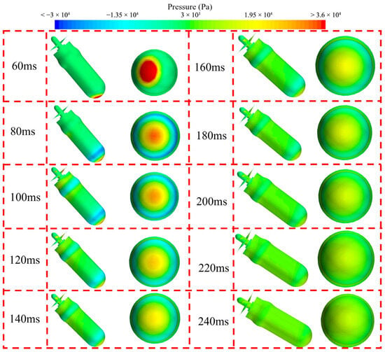
Figure 26.
The pressure contours of the UAUV’s surface during the water-entry process.
Figure 27 presents the pressure contours of the lower and upper surfaces of the four blades of the two propellers during the UAUV’s water-entry process. It can be seen from the figure that when the propellers are in the air, the pressures on both the upper and lower surfaces are close to zero. After the propellers touch the water surface, a high-intensity high-pressure region forms in the middle of the lower surfaces of the two blades of propeller #1 near the blade tips, and a similar high-pressure region also forms in the middle of the lower surfaces of the two blades of propeller #2 near the blade tips, but the intensity of this high-pressure area is significantly weaker than that of propeller #1. As the UAUV continues to enter the water, the intensity and area of the high-pressure regions on the lower surfaces of the two propellers rapidly decrease and eventually stabilize. During the UAUV’s water-entry process, a high-intensity, low-pressure region forms on the upper surfaces of the two propellers, which gradually disappears as the UAUV continues to enter the water. By comparing the changes in the pressure contours of the upper and lower surfaces of the two propellers, it can be seen that when the UAUV is completely submerged and its motion stabilizes, the pressure on the upper surfaces of the two propellers is slightly higher than that on the lower surfaces. At this time, the pressure difference between the upper and lower surfaces of the two propellers will generate a downward hydrodynamic force, promoting the UAUV’s submersion.
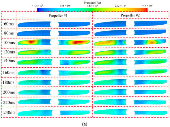
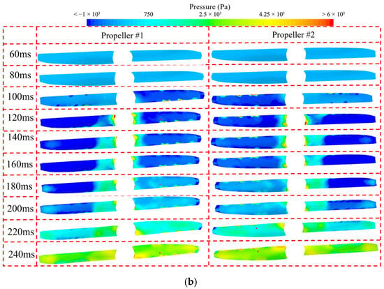
Figure 27.
The pressure contours of the two propellers during the water-entry process: (a) the lower surfaces; (b) the upper surfaces.
6. Analysis of the Process of the UAUV Entering the Air from the Water
The motion performance and hydrodynamic performance of the UAUV during the water-exit process directly affect whether it can achieve rapid, efficient, and stable water exit. Considering the actual application scenarios of UAUV, the angles for water entering air are set at 50°, 70°, and 90°, and the speed for water entering air is set at 4 m/s and 8 m/s.
6.1. The Influence of the Entry Angle on the UAUV’s Water-Exit Process
6.1.1. Motion Trajectory
Figure 28 shows the trajectory of the UAUV’s center of mass as it moves from the water into the air with different β. The dotted lines of different colors in the figure represent the trajectories of the center of mass of the UAUV. The solid dots of the same color on the dotted lines indicate the position of the center of mass of the UAUV when the nose just touches the water surface. As can be seen from the figure, when the UAUV exits the water in an inclined position relative to the water surface, its trajectory is a parabola, and its attitude changes significantly during the movement. When Uwa = 8 m/s, the UAUV’s trajectory is always a straight line before exiting the water. After the UAUV exits the water, its trajectory is significantly affected by β. As β increases, the curvature of the trajectory after the UAUV exits the water becomes smaller. When β equals 90°, it will again become a straight line. In addition, there will be a certain drop after the UAUV exits the water, which is due to the difference in density between water and air, causing the net buoyancy of the UAUV under the action of the fluid to significantly decrease after exiting the water, and thus resulting in a drop in its trajectory under the action of gravity. When Uwa = 4 m/s, the trajectory of the UAUV is similar to that of Uwa = 8 m/s. The difference is that the attitude of the UAUV will be significantly affected.
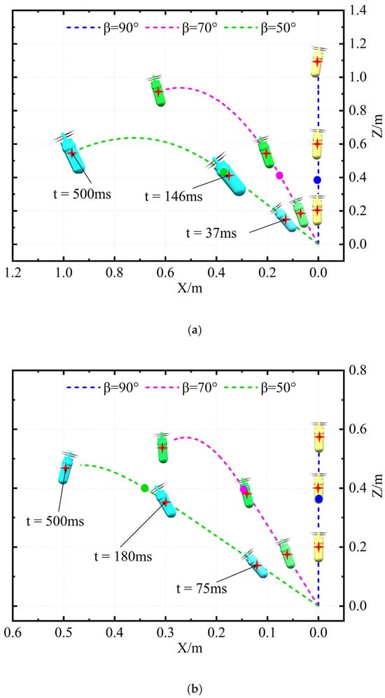
Figure 28.
The motion trajectory of the UAUV for air entering water: (a) Uwa = 8 m/s; (b) Uwa = 4 m/s.
6.1.2. Attack Angle
Figure 29
shows the attack angle θ of the UAUV as it moves from the water into the air with different β. It can be seen that during vertical water entry, for both Uwa = 8 m/s and Uwa = 4 m/s, the variation in θ is relatively small, exerting a limited influence on the emergence posture. As Uwa decreases, the variation trend of θ is slightly modulated; however, the overall trend remains stable. When the vehicle pitches upward for emergence, the attack angle θ exhibits an increasing trend. The rate of change of θ increases markedly with decreasing Uwa. For a given Uwa, the variation amplitude of θ becomes more pronounced at smaller β. This indicates that during the emergence process, the concurrent effect of β and Uwa governs the evolution of the angle of attack: a larger β combined with a smaller Uwa leads to a more dynamic variation in θ.
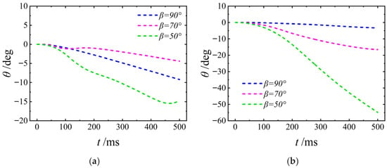
Figure 29.
The attack angle of the UAUV for water entering air: (a) Uwa = 8 m/s; (b) Uwa = 4 m/s.
6.1.3. Motion Velocity
Figure 30
presents the curves of the axial velocity Vz and lateral velocity Vx of the UAUV in the body-fixed coordinate system. It indicates that for a given Uwa, the Vz curves for different β values exhibit a consistent trend, suggesting that the initial inclination angle has a negligible influence on the trend of Vz. During the water-exit process, the Vz exhibits slight oscillations upon water surface contact. Because air resistance is significantly lower than water resistance, the post-exit evolution of Vz is predominantly governed by gravity, resulting in a distinctive velocity adjustment characteristic. For a fixed β, the magnitude of the lateral velocity Vx increases with Uwa. Under constant Uwa conditions, the variation amplitude of Vx increases as β decreases. This occurs because the β determines the geometry of the wetted surface between the vehicle and the fluid.
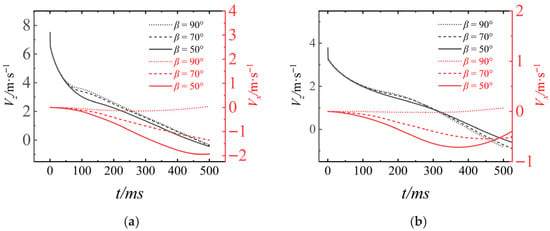
Figure 30.
The motion velocity of the UAUV in the body-fixed coordinate system: (a) Uwa = 8 m/s; (b) Uwa = 4 m/s.
6.1.4. Angular Velocity
The angular velocity ωy of the UAUV during the process of entering water from the air is shown in
Figure 31. As shown in the figure, the angular velocity ωy stabilizes as Uwa increases. At β = 90°, the ωy remains nearly constant. For β = 50°, the more inclined entry attitude induces a substantial hydrodynamic moment during the later stage, resulting in a significant increase in angular velocity. Lower Uwa leads to more pronounced angular velocity fluctuations due to hydrodynamic effects. At β = 50°, the ωy undergoes a sharp decrease followed by a subsequent increase. At β = 70°, a brief negative fluctuation is observed before a gradual recovery. At β = 90°, the ωy remains relatively stable, as mentioned previously. This behavior is attributed to the combined effect of β and Uwa. The β dictates the geometry of the wetted surface, while Uwa governs the magnitude and rate of the hydrodynamic forces. Together, these factors determine the resultant hydrodynamic moment, which ultimately dictates the distinct ωy responses.
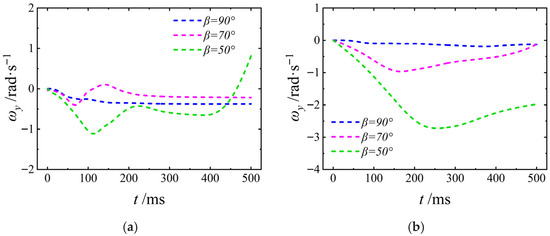
Figure 31.
The angular velocity of the UAUV in the body-fixed coordinate system: (a) Uwa = 8 m/s; (b) Uwa = 4 m/s.
6.1.5. Hydrodynamic Force
Figure 32
shows the variation process of the axial force Fz of the UAUV. As shown in the figure, a larger Uwa results in a more pronounced initial negative drop in axial force Fz, which is then followed by recovery and stabilization. At β = 50°, the more inclined entry posture leads to a greater initial component of the hydrodynamic impact force along the axial direction. Conversely, a smaller Uwa corresponds to a reduced amplitude in the initial axial force variation. Furthermore, the overall magnitude of Fz is lower across all tested angles under these conditions. This phenomenon occurs because Uwa governs the kinetic energy of the incoming flow and consequently the impact intensity, while β influences the geometry of interaction between the flow and the vehicle’s axial direction. In combination, these parameters cause the axial hydrodynamic forces to undergo a significant transient change due to the initial impact, which is followed by a gradual stabilization as the flow field develops around UAUV and its attitude adjusts.
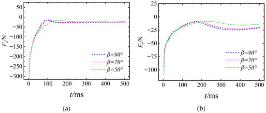
Figure 32.
The axis force of the UAUV in the body-fixed coordinate system: (a) Uwa = 8 m/s; (b) Uwa = 4 m/s.
Figure 33 presents the time–history curve of the UAUV’s lateral force Fx. It demonstrates that a larger Uwa corresponds to a more intense initial fluctuation in the vertical force. Conversely, a smaller Uwa results in a more gradual overall change and a reduced fluctuation amplitude of the vertical force across all inclination angles. This behavior occurs because Uwa governs the intensity of the hydrodynamic impact, while β influences the geometry of the interaction between the fluid and the vehicle along the vertical axis. Under their combined influence, a high Uwa leads to an intense hydrodynamic impact, thereby producing a significant initial change in the vertical force. Subsequently, the force stabilizes gradually as the UAUV’s attitude adjusts and the surrounding flow field develops. Conversely, at a low Uwa, the available fluid kinetic energy is lower, resulting in a more gradual evolution of the lateral force Fx.
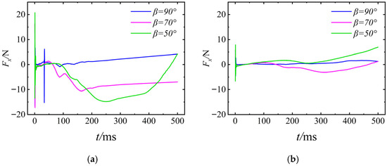
Figure 33.
The lateral force of the UAUV in the body-fixed coordinate system: (a) Uwa = 8 m/s; (b) Uwa = 4 m/s.
6.1.6. Hydrodynamic Moment
The hydrodynamic moment My of the UAUV during the water-entry process is shown in
Figure 34. It can be seen that a larger Uwa corresponds to a more pronounced initial fluctuation in hydrodynamic moment My. At β = 90°, the My remains relatively stable. Conversely, a lower Uwa results in a more gradual overall change in My, accompanied by a reduced fluctuation amplitude across all inclination angles β. This behavior is attributed to the fact that Uwa governs the kinetic energy of the incoming flow and thus the impact intensity, while β dictates the contact geometry and the resulting hydrodynamic pressure distribution. Under a high Uwa condition, the intense impact induces a prominent initial dynamic variation in My. During small-angle immersion (low β), the UAUV’s attitude adjustment is more complex, and the flow field and associated pressure distribution evolve more substantially throughout the process. Conversely, under low Uwa conditions, the weaker fluid impact results in a more gradual dynamic variation in the My.
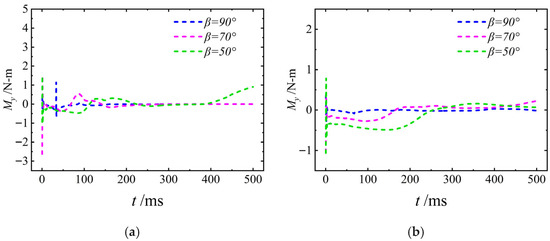
Figure 34.
The hydrodynamic torque of the UAUV in the body-fixed coordinate system: (a) Uwa = 8 m/s; (b) Uwa = 4 m/s.
6.2. Cavity Evolution and Jet Formation
The cavity evolutions at water-exit angles of β = 50°, 70°, and 90° are selected as examples to illustrate the typical characteristics of cavity formation with the UAUV motion. Figure 35 and Figure 36 show the cavity evolution and two-phase diagram with these entry angles during water exit with Uwa = 8 m/s. For ease of analysis, we define the position of the UAUV in the figure as follows: our left-hand side is the left side of the UAUV, and our right-hand side is the right side of the UAUV. From the figure, it can be seen that when the UAUV emerges from the water, the right side of the propeller shaft and the right side of the propeller blades will first come into contact with the water surface, causing a gradually rising water mound to form on the water surface. As the HUAV continues to emerge from the water, this water mound keeps expanding. Under the action of the propeller, this water mound will break apart. As the UAUV continues to emerge from the water, its body along with the surrounding water will produce splashing water droplets. After the UAUV completely emerges from the water, the water droplets will fall back onto the water surface under the force of gravity, forming splashing water surfaces.
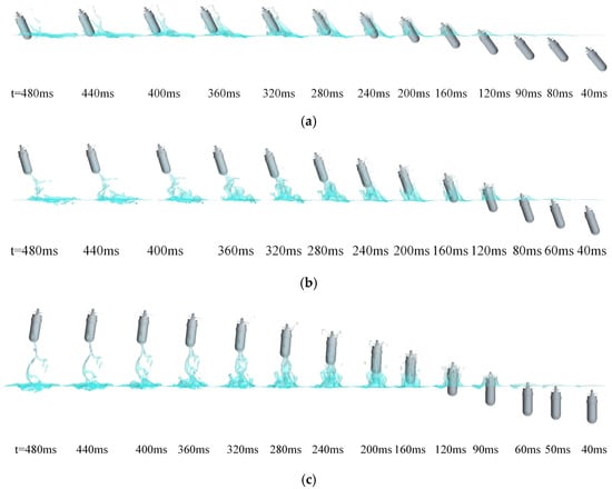
Figure 35.
Cavity evolution of the water entry at different water-exit angles: (a) β = 50°; (b) β = 70°; (c) β = 90°.
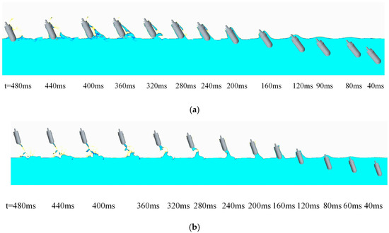

Figure 36.
The two-dimensional two-phase diagram of water and air during the water-exit process of the UAUV: (a) β = 50°; (b) β = 70°; (c) β = 90°.
When β is 50°, the right blade of the propeller on the UAUV starts to hit the water surface during the water-exit process (t = 90 ms). Immediately after that, the right front side of the propeller shaft and the right front side of the UAUV’s hull also come into contact (t = 120 ms). This causes the fluid particles near them to gain kinetic energy and splash outward during the impact, leading to the expansion of the cavity (t = 120 ms). The extent of the cavity expansion is related to the impact force received by the fluid particles. Since the UAUV impacts the water surface at an inclined angle, the fluid particles on the right front side of the UAUV receive a greater impact force than those on the left side. The external area on the left front side of the UAUV is in the backflow region, where the fluid particles receive a smaller velocity perpendicular to the wall and encounter greater resistance when extending to the upper-left direction. Therefore, a smaller opening cavity is formed in this specific region (t = 120 ms). Under the impact on the right front side of the UAUV, the fluid particles near the right exit jet zone gain more kinetic energy from the UAUV’s extrusion, thereby generating more obvious splashes and open cavity over the water surface (t = 160 ms). As the cavity expanded and its volume increased, eventually it could no longer continue to expand under the influence of gravity, and was thus broken through by the UAUV, forming splashing liquid droplets surrounding the UAUV (t = 240 ms). After that, the UAUV broke through the water surface, and the splashing droplets produced by it rose to a certain height under the influence of inertia, then fell back to the water surface under the force of gravity, forming a violent spray of water. When β is equal to 70° and 90°, the evolution process of the cavity is similar to that when β is equal to 50°. No further description will be provided.
6.3. Pressure Contours
Figure 37 shows the pressure contours of the UAUV when the Uwa is 8 m/s and the β is 50°. From the figure, it can be seen that when the UAUV starts to move, a high-intensity high-pressure area will be generated at the head of the propeller shaft and the upper surface of the UAUV’s hull. This is because the rapid movement of the UAUV causes a transient rapid compression of the surrounding fluid, resulting in a high-pressure area on the surface where it interacts with the fluid. This high-pressure area generates a large hydrodynamic force. Since the upper surface of the UAUV is perpendicular to the x-axis, this hydrodynamic force only contributes in the x-axis direction. At this time, Fx shows a relatively large negative value along the x-axis. Additionally, at this moment, the surface of the UAUV’s hull is covered by low-pressure and high-pressure areas, so Fz experiences significant fluctuations. As the UAUV moves, the intensity of this high-pressure area gradually decreases, and thus the amplitude of Fx also gradually decreases. When the UAUV completely emerges from the water, the pressure on the UAUV’s surface is almost zero. At this time, Fx and Fz are all generated by the component of the UAUV’s gravity, and thus tend to a constant value.
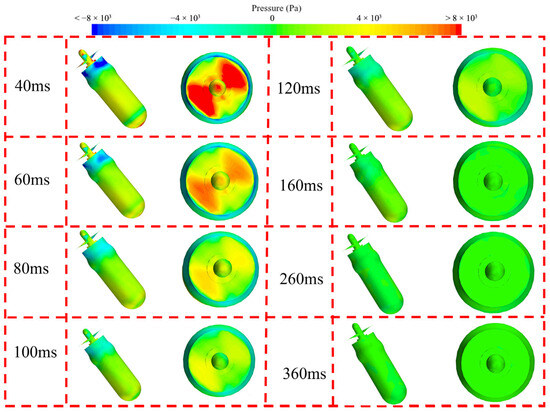
Figure 37.
The pressure contours of the UAUV’s surface during the water-exit process.
This work focuses on introducing a new type of UAUV that differs from traditional structures and elaborates on its internal design and working conditions. A numerical simulation method is proposed to analyze the submersion and emergence processes of the new structure, and to determine the mechanism of the influence on the hydrodynamic characteristics. However, the computational model in this paper is simplified and only preliminary numerical calculations are conducted, resulting in limitations in the research. Further studies will be carried out in the future on aspects such as the attitude control of the propulsion system self-navigation and the cross-media operation of the vector steering system.
7. Conclusions
This paper proposes an innovative unmanned aerial–underwater vehicle (UAUV) propelled by coaxial twin propellers, with its overall architecture and subsystem designs systematically elaborated. Due to the significant differences in density and dynamic viscosity between air and water, transient impact loads are inevitably encountered by the UAUV during cross-media motion. To address this, a numerical simulation framework suitable for cross-domain motion of the UAUV was established and validated using STAR-CCM+, incorporating the VOF multiphase model, the DFBI six-degree-of-freedom coupling method, and the SST k-ω turbulence model. This model effectively captures the evolution of the air–water interface, rigid-body motion response, and turbulent flow characteristics during water-entry and water-exit processes.
Numerical simulations and analyses were conducted on the cross-domain transitions of the UAUV—from water to air and from air to water—under varying attack angles and velocities. Key findings include the following: When the water-entry speed Uaw is relatively high, the UAUV’s entry trajectory is approximately linear. However, when the Uaw is low, as water-entry angle β increases, the UAUV’s movement trajectory will exhibit continuous undulating motion. The attack angle θ, when Uaw is large, remains in an increasing trend as β decreases. But when Uaw is small, θ first increases and then decreases, indicating that the UAUV’s motion is unstable at a lower entry speed. When the UAUV is performing a water-exit movement, if it is inclined with respect to the water surface, its movement trajectory will be parabolic. Moreover, during the water-exit process, its attitude will undergo significant changes. The smaller the water-exit speed and angle, the greater the change in attitude. Even so, it may cause the direction of the UAUV’s attitude angle to deviate. Cavitation evolution and liquid splashing patterns observed during both entry and exit processes further corroborate the above dynamic behaviors.
This paper innovatively proposes a UAUV based on coaxial twin-propeller propulsion. Compared with the traditional configuration, it has strong potential in terms of rapid, efficient, and highly stable cross-domain movement. The findings of this study provide key theoretical insights and technical references for optimizing the structural design of UAUVs.
Author Contributions
Conceptualization, Y.F. and Q.G.; methodology, J.W., Y.F., and H.J.; software, J.W., Y.F., G.Z., Q.G., H.J., and Z.Z.; validation, J.W. and Y.F.; formal analysis, J.W., Y.F. and G.Z.; investigation, J.W., Y.F., and G.Z.; resources, Y.F.; data curation, J.W., Y.F., G.Z., Q.G., H.J., and Z.Z.; writing—original draft preparation, Y.F. and G.Z.; writing—review and editing, Y.F.; visualization, J.W.; supervision, Y.F.; project administration, Y.F.; funding acquisition, Y.F. All authors have read and agreed to the published version of the manuscript.
Funding
This research was funded by the Hunan Provincial Natural Science Foundation of China, grant number 2023JJ40669; the National Undergraduate Innovation and Entrepreneurship Training Program, grant number S202390002050; the National Natural Science Foundation of China, grant number 52201387; Research Project Funding of National University of Defense Technology of China, grant number ZK22-60; and the National Key Laboratory Foundation, grant number WDZC20245250309.
Data Availability Statement
The datasets used and analyzed during the current study are available from the corresponding author on reasonable request.
Conflicts of Interest
The authors declare no conflicts of interest.
References
- Huang, T.; Lei, Q.; Guo, S.; Li, C.; Ma, G.; Sun, H.; Peng, S. YingLong-I: A Hybrid Aerial Underwater Vehicle Using Integrated Coaxial Counter-Rotating Propulsion. IEEE Robot. Autom. Lett. 2025, 10, 9352–9359. [Google Scholar] [CrossRef]
- Li, C.; Guo, S. Characteristic evaluation via multi-sensor information fusion strategy for spherical underwater robots. Inf. Fusion 2023, 95, 199–214. [Google Scholar] [CrossRef]
- Li, A.; Guo, S.; Li, C. An Improved Motion Strategy with Uncertainty Perception for the Underwater Robot Based on Thrust Allocation Model. IEEE Robot. Autom. Lett. 2025, 10, 64–71. [Google Scholar] [CrossRef]
- Lu, D.; Xiong, C.; Zhou, H.; Lyu, C.; Hu, R.; Yu, C.; Zeng, Z.; Lian, L. Design, fabrication, and characterization of a multimodal hybrid aerial underwater vehicle. Ocean Eng. 2020, 219, 108324. [Google Scholar] [CrossRef]
- Wagter, C.; Ruijsink, R.; Smeur, E.; Hecke, K.; Tienen, F.; Horst, E.; Remes, B. Design, control, and visual navigation of the DelftaCopter VTOL tail-sitter UAV. J. Field Robot. 2018, 35, 937–960. [Google Scholar] [CrossRef]
- Kimball, P.; Clark, B.; Scully, M.; Richmond, K.; Flesher, C.; Lindzey, L.; Harman, J.; Huffstutler, K.; Lawrence, J.; Lelievre, S.; et al. The ARTEMIS under-ice AUV docking system. J. Field Robot. 2018, 35, 299–308. [Google Scholar] [CrossRef]
- Lyu, C.; Lu, D.; Xiong, C.; Hu, R.; Jin, Y.; Wang, J.; Zeng, Z.; Lian, L. Toward a gliding hybrid aerial underwater vehicle: Design, fabrication, and experiments. J. Field Robot. 2022, 39, 543–556. [Google Scholar] [CrossRef]
- William, S.; Warren, W.; Mark, A.; Matthew, B.; Kara, P. Dynamic Modeling of Passively Draining Structures for Aerial–Aquatic Unmanned Vehicles. IEEE J. Ocean. Eng. 2020, 45, 840–850. [Google Scholar]
- Kollmorgen. Sea Sentry Organic Submarine Launched UAV; Kollmorgen Corporation: Radford, VA, USA, 2009. [Google Scholar]
- Weisshaar, T. Morphing UAUV systems: Historical perspectives and future challenges. J. UAUV 2013, 50, 337–353. [Google Scholar]
- Eubank, R.; Atkins, E. Autonomous Guidance and Control of the Flying Fish Ocean Surveillance Platform; American Institute of Aeronautics and Astronautics: Reston, VA, USA, 2009. [Google Scholar]
- Liang, J.; Yao, G.; Wang, T.; Yang, X.; Zhao, W.; Song, G.; Zhang, Y. Wing load investigation of the plunge-diving locomotion of a gannet Morus inspired submersible UAUV. Sci. China (Technol. Sci.) 2014, 57, 156–168. [Google Scholar]
- Wang, T.; Yang, X.; Liang, J.; Yao, G.; Zhao, W. CFD based investigation on the impact acceleration when a gannet impacts with water during plunge diving. Bioinspir. Biomim. 2013, 8, 036006. [Google Scholar] [CrossRef]
- Stewart, W.; Weisler, W.; MacLeod, M.; Powers, T.; Defreitas, A.; Gritter, R.; Anderson, M.; Peters, K.; Gopalarathnam, A.; Bryant, M. Design and demonstration of a seabird-inspired fixed-wing hybrid UAV-UUV system. Bioinspir. Biomim. 2018, 13, 056013. [Google Scholar] [CrossRef]
- Sun, Y.; Liu, X.; Cao, K.; Shen, H.; Li, Q.; Chen, G.; Xi, J.; Ji, A. Design and Theoretical Research on Aerial-Aquatic Vehicles: A Review. J. Bionic Eng. 2023, 6, 2512–2541. [Google Scholar] [CrossRef]
- Kova, M.; Siddall, R. Launching the AquaMAV: Bioinspired design for aerial–aquatic robotic platforms. Bioinspir. Biomim. 2014, 9, 031001. [Google Scholar]
- Beber, I.; Hazard, S.; Puerto, D.; Ernesto, H. Spatial ecology and philopatric tendencies of whitespotted eagle ray, Aetobatus narinari, in Cozumel, Mexico. Environ. Biol. Fishes 2025, 108, 591–609. [Google Scholar] [CrossRef]
- Li, Z.; Zhang, W.; Huang, X.; Ye, X.; Chen, Y.; Jiang, Q. Water-exit dynamics and system identification for a hybrid aerial underwater vehicle. Eng. Appl. Comput. Fluid Mech. 2025, 19, 1994–2060. [Google Scholar] [CrossRef]
- Muhammed, C.; Adib, A.; Kabita, A.; Damian, G. A hybrid method based on logic predictive controller for flexible hybrid microgrid with plug-and-play capabilities. Appl. Energy 2024, 359, 122752. [Google Scholar]
- Zhou, H.; Wei, Z.; Hu, W. Hydrodynamic performance and maneuverability design for a compound eVTOL configuration based unmanned aerial underwater vehicle. Ocean Eng. 2025, 319, 120210. [Google Scholar] [CrossRef]
- Da, R.; Evald, P.; Drews, P.; Neto, A.; Horn, A.; Azzolin, R.; Botelho, S. A Comparative Study on Sigma-Point Kalman Filters for Trajectory Estimation of Hybrid Aerial-Aquatic Vehicles. In Proceedings of the IEEE International Conference on Intelligent Robots and Systems, Madrid, Spain, 1–5 October 2018; pp. 7460–7465. [Google Scholar]
- Lu, D.; Xiong, C.; Lyu, B.Z.; Zeng, Z.; Lian, L. Multi-mode hybrid aerial underwater vehicle with extended endurance. In Proceedings of the 2018 Oceans—MTS/IEEE Kobe Techno-Oceans, OTO, Kobe, Japan, 28–31 May 2018; pp. 1–7. [Google Scholar]
- Liu, X.; Dou, M.; Yan, R.; Huang, D.; Gao, S.; Wang, B.; Cui, J.; Ren, Q.; Dou, L.; Gao, Z.; et al. TJ-FlyingFish: An Unmanned Morphable Aerial-Aquatic Vehicle System. Unmanned Syst. 2024, 12, 409–428. [Google Scholar] [CrossRef]
- Yao, G.; Li, Y.; Zhang, H.; Jiang, Y.; Wang, T.; Sun, F.; Yang, X. Review of hybrid aquatic-aerial vehicle (HAAV): Classifications, current status, applications, challenges and technology perspectives. Prog. Aerosp. Sci. 2023, 139, 100902. [Google Scholar] [CrossRef]
- Jin, Y.; Zeng, Z.; Lian, L. Nezha-SeaDart: A tail-sitting fixed-wing vertical takeoff and landing hybrid aerial underwater vehicle. J. Field Robot. 2025, 42, 137–152. [Google Scholar] [CrossRef]
- Yu, H.; Ben, M. Survey on the Development of Aerial–Aquatic Hybrid Vehicles. Unmanned Syst. 2021, 9, 263–282. [Google Scholar]
- Lock, R.; Burgess, S.; Vaidyanathan, R. Multi-modal locomotion: From animal to application. Bioinspir. Biomim. 2014, 9, 011001. [Google Scholar] [CrossRef]
- Xu, T.; Luo, Y.; Hou, Z.; Huang, Q.; Pan, G. Hydrodynamics of jet-flapping combinatorial propulsion in a squid-like swimmer: A study on different coordination modes. Phys. Fluids 2025, 37, 061909. [Google Scholar] [CrossRef]
- Eubank, R.; Bradley, J.; Atkins, E. Energy-aware multiflight planning for an unattended seaplane: Flying fish. J. Aerosp. Inf. Syst. 2017, 14, 73–91. [Google Scholar] [CrossRef]
- Dario, F.; Robert, J. Science, technology and the future of small autonomous drones. Nature 2015, 521, 460–466. [Google Scholar] [CrossRef]
- Yang, X.; Chen, Y.; Chang, L.; Ariel, A.; Nestor, O. Bee+: A 95-mg Four-Winged Insect-Scale Flying Robot Driven by Twinned Unimorph Actuators. IEEE Robot. Autom. Lett. 2019, 4, 4270–4277. [Google Scholar] [CrossRef]
- Dimitris, P.; George, K.; Spyros, V.; Katerina, M.; Pantelis, V.; Diego, G. A Novel Drone Design Based on a Reconfigurable Unmanned Aerial Vehicle for Wildfire Management. Drones 2024, 8, 203. [Google Scholar] [CrossRef]
- Wei, J.; Sha, Y.; Hu, X.; Yao, J.; Chen, Y. Aerodynamic Numerical Simulation Analysis of Water–Air Two-Phase Flow in Trans-Medium UAUV. Drones 2022, 6, 236. [Google Scholar] [CrossRef]
- Wang, S.; Guedes, S. Numerical study on the water impact of 3D bodies by an explicit finite element method. Ocean Eng. 2014, 78, 73–88. [Google Scholar] [CrossRef]
- Jiang, C.; Shuai, Z.; Zhang, X.; Li, W.; Li, F. Numerical study on the transient behavior of water-entry supercavitating flow around a cylindrical projectile influenced by turbulent drag-reducing additives. Appl. Therm. Eng. 2016, 104, 450–460. [Google Scholar] [CrossRef]
- Ma, Z.; Qian, L.; Marti’nez-Ferrer, P.; Causon, D.; Mingham, C.; Bai, W. An overset mesh based multiphase flow solver for water entry problems. Comput. Fluids 2018, 172, 689–705. [Google Scholar] [CrossRef]
- Derakhshanian, M.; Haghdel, M.; Alishahi, M.; Haghdel, A. Experimental and numerical investigation for a reliable simulation tool for oblique water entry problems. Ocean Eng. 2018, 160, 231–243. [Google Scholar] [CrossRef]
- Peng, W.; Wei, Q. Improved prediction of 3-D water entry with a CIP method and parallel computing. Ocean Eng. 2018, 164, 426–442. [Google Scholar] [CrossRef]
- Sun, P.; Zhang, A.; Salvatore, M.; Furen, M. An accurate and efficient SPH modeling of the water entry of circular cylinders. Appl. Ocean Res. 2018, 72, 60–75. [Google Scholar] [CrossRef]
- Namkoong, K.; Choi, H.; Yoo, J. Numerical Analysis of Two-Dimensional Motion of a Freely Falling Circular Cylinder in an Infinite Fluid. Trans. Korean Soc. Mech. Eng. B 2004, 28, 713–725. [Google Scholar] [CrossRef]
- Madjid, A.; Navid, N.; Pouya, M.; Araz, T. Numerical simulation of vortex-induced vibration of a smooth circular cylinder at the subcritical regime. Proc. Inst. Mech. Eng. Part M J. Eng. Marit. Environ. 2022, 236, 916–937. [Google Scholar]
- Xiang, G.; Wang, S.; Soares, C. Study on the motion of a freely falling horizontal cylinder into water using OpenFOAM. Ocean Eng. 2020, 196, 106811. [Google Scholar] [CrossRef]
- Menter, F.R. A comparison of some recent eddy-viscosity turbulence models. J. Fluids Eng. Trans. ASME 1996, 118, 514–519. [Google Scholar] [CrossRef]
- Zhang, G.; Wang, J.; Feng, Y.; Jin, H.; Ge, Q.; Xu, X.; Li, J. Experimental and numerical investigation on the hydrodynamic performance of an amphibious vehicle under the interaction of traveling mechanism mudguard and waterjet propulsor duct. Ocean Eng. 2025, 340, 122426. [Google Scholar] [CrossRef]
- Feng, Y.; Zhang, G.; Wang, J.; Zhang, Z.; Xu, X. Numerical investigation of the hydrodynamic characteristics of a light high-speed amphibious vehicle in still water under oblique inflow conditions. Phys. Fluids 2025, 37, 047150. [Google Scholar] [CrossRef]
- Lyu, X.; Wei, Z.; Tang, H.; New, T.; Li, H. On the motion of a falling circular cylinder in flows after water entry. In Proceedings of the International conference on experimental mechanics, Hong Kong, China, 7–9 January 2015; p. 9302. [Google Scholar]
Disclaimer/Publisher’s Note: The statements, opinions and data contained in all publications are solely those of the individual author(s) and contributor(s) and not of MDPI and/or the editor(s). MDPI and/or the editor(s) disclaim responsibility for any injury to people or property resulting from any ideas, methods, instructions or products referred to in the content. |
© 2025 by the authors. Licensee MDPI, Basel, Switzerland. This article is an open access article distributed under the terms and conditions of the Creative Commons Attribution (CC BY) license (https://creativecommons.org/licenses/by/4.0/).