Article

Cooperative Path-Following Control for Multi-UAVs Considering GNSS Denial

1
School of Instrumentation and Electronics, North University of China, Taiyuan 030051, China
2
National Key Laboratory of Electromagnetic Space Security, Tianjin 300300, China
*
Authors to whom correspondence should be addressed.
Drones 2025, 9(11), 749; https://doi.org/10.3390/drones9110749
Submission received: 17 September 2025 / Revised: 17 October 2025 / Accepted: 23 October 2025 / Published: 28 October 2025

Highlights

What are the main findings?
  • This study proposes a control framework that decomposes complex collaborative problems into simpler path-tracking and velocity-synchronization subtasks through a virtual arc-length cooperation strategy, significantly reducing controller complexity.
  • This framework integrates an Unknown System Dynamics Estimator (USDE) to compensate for external disturbances in real time. By combining a dynamic event-triggering mechanism with a position observer, it significantly reduces communication load between UAVs.
What is the implication of the main finding?
  • Simulation results validate that even under sustained external wind disturbances, this framework achieves feasible path following and stable formation maintenance, demonstrating its exceptional robustness and control performance.
  • This method provides a practical and theoretically sound solution for deploying autonomous multi-UAV systems in complex, uncertain, and resource-constrained environments.

Abstract

This paper investigates the cooperative path-following control problem for multiple unmanned aerial vehicles (UAVs) under Global Navigation Satellite System (GNSS) denial conditions. To achieve equidistant distribution and uniform velocity motion within the swarm, a distributed control strategy based on Linear Matrix Inequalities (LMI) is proposed. Additionally, a novel virtual arc-length cooperation strategy is introduced, decomposing the formation maintenance problem into two subtasks: path following and velocity synchronization. This approach reduces control complexity and significantly minimizes frequent velocity cooperation issues caused by angular separation errors. To enable online estimation and compensation for model uncertainties and external disturbances, a USDE is incorporated, offering enhanced adaptability to time-varying disturbances. Simultaneously, a dynamic event-triggered mechanism (ETM) is designed to exchange neighbor information only when necessary, substantially reducing communication load. Global consistent ultimately bounded stability of the closed-loop system is rigorously proven using Lyapunov theory. Finally, validation results from the simulation platform demonstrate the proposed method’s certain feasibility and effectiveness in practical applications.

1. Introduction

In recent years, UAVs have emerged as widely used equipment in both military and civilian sectors. Their high flexibility and relatively low cost render them valuable assets in a range of operations, including counter-terrorism reconnaissance [1,2], homeland mapping [3], disaster relief [4], environmental monitoring [5], and aerial photography [6]. In most of these applications, the operational nature of drones involves completing tasks by flying through a series of spatial positions or paths, with or without time constraints. This requirement classifies flight modes into two categories: trajectory tracking [7] and path-following [8]. Trajectory tracking requires the UAV to reach specific locations within predetermined times. Conversely, path-following demands the UAV to align with a geometric path using any feasible velocity curve. Trajectory tracking is generally employed for dynamic target tracking, while path-following is used for UAV tasks including cruising, reconnaissance, obstacle avoidance, and terrain tracking. Thus, the path-following law for UAVs is crucial for replacing pilot maneuvers [9]. Furthermore, in complex environments where GNSS signals are lost or subject to interference, designing an efficient path-following control strategy becomes particularly crucial.
Regarding the issue of path-following control for UAVs, the academic community has conducted extensive and long-standing research. Some of this research originated in the last century [10], and a great deal of meaningful experimentation has been undertaken. Today, there are numerous outstanding works in this field. Wang et al. [11] transformed the path-following problem into an error-tracking control problem by introducing the Frenet coordinate system. A hybrid path-following control law was designed in ref. [12], theoretically proving that even under velocity constraints of fixed-wing UAVs, this control law can drive the path-following error to zero while converging the arc-length distance between UAVs to the desired value. Chen et al. [13] combined a sliding mode controller with S-plane control to design an inner–outer loop control structure, enhancing the accuracy of fixed-wing UAVs in three-dimensional path tracking. Pham et al. [14] proposed a distributed cooperative guidance algorithm using vector field control to manage lateral errors, ensuring robust path tracking. Kim et al. [15] proposed an adaptive control law based on backstepping control. By designing virtual target points and converting heading rate commands into roll angle commands, the UAV achieves asymptotic convergence to the path. An adaptive nonlinear model predictive controller was designed in ref. [16], dynamically adjusting the prediction time domain based on path curvature to enhance tracking accuracy. Xue et al. [17] visually demonstrates the adaptability of path tracking algorithms across different scenarios by comparing the Carrot chasing algorithm with the pure line-of-sight (LOS) pursuit algorithm (PLOS). Notably, most path-following methods are developed under idealized conditions. When confronted with more complex paths, wind disturbance modeling, and real-time constraints, trained models may fail.
In line with the aforementioned approach, UAV path-following algorithms are evolving towards greater intelligence, adaptability, and robustness. Yi et al. [18] formulated the path-following problem as a trajectory stability issue, designing a static state feedback controller based on immersion and invariance techniques to ensure stable motion along the predetermined path. The path-following problem was addressed by transforming it into an ensemble stabilization problem in ref. [19,20]. It employs transversal feedback linearization (TFL) and ensemble stabilization methods to convert system dynamics into a canonical form, facilitating the linearization of transversal dynamics and the partial linearization of tangential dynamics. Zhang et al. [21] proposed a curved path-following method for fixed-wing UAVs by combining the vector field approach with input-to-state stabilization. An adaptive velocity parameter is designed to guide the virtual target point along the path. Xu et al. [22] proposed a Predictive Path-Following Control (PPFC) framework for tiltrotor quadcopters by modelling their dynamics as a fully-actuated system (FAS), thereby transforming the path-following problem into a trajectory tracking problem. To accomplish the parametric path-following task, specific guidance rules and cooperative strategies were formulated in ref. [23,24] by integrating backstepping control with LOS guidance. Lee et al. [25] attained terrain following under wind disturbances by integrating model predictive control with backstepping control using a nonlinear disturbance observer. Nonetheless, certain fundamental limitations exist in many of the aforementioned control approaches. For example, model predictive control and backstepping control rely on accurate system models, whereas addressing constrained optimization problems demands substantial computational resources, particularly for multivariate and complex constraints. While PID controllers exhibit less reliance on the system model, their effectiveness in complex dynamic environments is highly dependent on parameter tuning, which typically necessitates extensive experiments and experience. The adoption of immersion and invariance techniques, with transversal feedback linearization (TFL) and ensemble stabilization methods, is inadequate for ensuring path attraction, resulting in potential deviations of the controlled intelligences from the intended path. Therefore, the development of a novel cooperative path-following control strategy to tackle the above problem remains an outstanding challenge.
However, most previous path-following control strategies were developed at the kinematic level, indicating that these methods cannot ensure the robustness and stability of the system’s performance when confronted with uncertainties. In the development of practical UAV control systems, it is challenging to mitigate uncertainties such as model nonlinearities [26] and adverse external environment disturbances [27], which can significantly affect both the transient response and steady-state performance of the system. To compensate for the uncertainty arising from the environment and the system model, a sliding mode control method based on a USDE for servo mechanisms with indeterminate dynamics and modeling uncertainties was first proposed in [28]. This method involved the construction of an invariant manifold through the introduction of auxiliary variables based on a first-order low-pass filter. This invariant manifold facilitates the design of a USDE with only one tuning parameter (i.e., the time constant of the filter), presenting a simpler structure compared to alternative estimators, and the USDE is used to compensate for the effects of unknown system dynamics, as it can be easily integrated into the control synthesis. Therefore, incorporating a USDE into the path-following controller for perturbation compensation and to ensure the convergence of system stability is a valuable investigation. However, the simultaneous execution of tasks by each UAV would inevitably result in resource wastage due to the frequent updates of the controller. The event-triggered mechanism [29,30,31] ensures the stability and adaptability of the control system while realizing non-periodic sampling. Its core concept is to decide whether to initiate the control task according to the change of the system state, rather than adhering to a fixed time interval. This approach can markedly diminish superfluous signal transmission and the expenditure of computational resources, thus improving the efficiency and performance of the system and triggering the control task when the measurement error of the system state exceeds a certain fixed threshold. An event-triggered strategy proposed in Literature [29] reduces the sampling frequency of the controller and conserves network communication resources, allowing a multi-intelligent body system to track the state of the virtual leader despite system nonlinearities. Lv et al. [30] proposed a neural network control method based on an event-triggered mechanism that reduces unnecessary data transfers, hence conserving communication resources, activated solely when predefined event conditions are met. In ref. [31], an event-triggering condition is defined to avoid the Zeno behavior and reduce communication costs from sensor to observer. Therefore, the design of a controller with a non-periodic state update characteristic while guaranteeing the stable performance of data transmission in cooperative UAV following is a pressing issue in this paper.
This paper investigates the cooperative path-following control problem for multiple UAVs under model uncertainty and external disturbances. To address the two major challenges of high computational complexity and excessive communication load in traditional cooperative control, a distributed control scheme is proposed. First, a virtual arc length cooperation strategy is introduced, decoupling the formation maintenance problem into two independent subtasks: path following and velocity synchronization. This approach not only reduces control complexity but also significantly minimizes frequent velocity cooperation caused by position errors. The controller design, based on LMI theory, ensures high-precision tracking. Second, to enable online estimation and compensation for system uncertainties and external time-varying disturbances, an USDE is designed to enhance the system’s dynamic adaptability and robustness. Finally, to further reduce communication overhead, the dynamic event-triggering mechanism is integrated with the position observer to ensure the UAV exchanges information with neighboring nodes only when necessary. Global consistent ultimately bounded stability of the closed-loop system is proven via Lyapunov theory. Simulation experiments validate that this method achieves precise path following while effectively reducing resource consumption, demonstrating superior overall performance. The main contributions are as follows:
1.
A cooperative control strategy based on virtual arc-length decoupling is proposed. This strategy decomposes the complex multi-UAV collaborative following problem into two simpler subtasks: simpler path tracking and velocity synchronization along the path. Unlike traditional trajectory tracking that requires simultaneous satisfaction of spatial and temporal constraints, this method not only significantly reduces the design complexity of distributed controllers but also enhances the smoothness and stability of the entire formation’s trajectory motion by minimizing unnecessary frequent velocity adjustments.
2.
An integrated control framework combining a USDE with a dynamic event-triggering mechanism is introduced to enhance system robustness and resource efficiency. The USDE guarantees precise command following even under external disturbances; utilizing a position observer, the designed event-triggering mechanism ensures communication occurs only when necessary. This approach reduces network load and avoids resource waste caused by frequent updates to the control system.
The structure of this paper is as follows. Section 2 presents the UAV motion model and control objectives. Section 3 carries out the design of the controller. Section 4 utilizes Lyapunov’s principle to demonstrate the stability of the whole system. Simulation and experimental results are given in Section 5. Section 6 draws the conclusion and outlook.

2. Motion Model and Control Objectives

2.1. Algebraic Graph Theory

In this paper, a directed graph is used to describe the network architecture among N 1 racks of UAVs, denoted as G = ( V , E ) , where V = 1 , 2 , , N 1 represents the vertex set of nodes of the directed graph, and E V × V denotes the set of edges of the directed graph. ( i , j ) denotes that node i is adjacent to j. When ( i , j ) E , a i j = 1 , otherwise, a i j = 0 . Assume that there is no self-loop in the topological graph, i.e., a i i = 0 . The neighbor set of node i is denoted as D i = j a i j = 1 . Let D i denote the cardinality of the set D i . The Laplace matrix L R N × N is defined as follows:
l i j = a i j , j i D i , j = i .
In a UAV system, only the virtual leader UAV can receive the position and velocity signals directly, and the given signals are taken as the outputs of the virtual leader UAV designated as 0. The communication topology between the navigator and the follower is represented by the diagonal array B = d i a g { b 1 , b 2 , , b N 1 } . If the i th UAV can communicate with the navigator, then b i > 0 , otherwise, b i = 0 .

2.2. Input-to-State Stability

Definition 1.
Define a differential system as follows:
x ˙ = ϕ ( t , x , δ ) , x ( 0 ) = x 0 ,
where ϕ : [ 0 , ) × R n × R m R n being segmentally continuous in t and locally Lipschitz in x and δ.
Let Ω : [ 0 , ) × R n R be a continuous and differentiable function such that the following are obtained:
α 1 ( | | x | | ) Ω ( t , x ) α 2 ( | | x | | ) ,
Ω t + Ω x ϕ ( t , x , δ ) Q ( x ) | | x | | ( | | δ | | ) > 0 .
( t , x , δ ) [ 0 , ) × R n × R m ,with α 1 and α 2 being class K functions, Q ( x ) is continuous positive definite on R n . Next, when the input δ is bounded, the system (2) satisfies the input-to-state stable (ISS) principle, where η = α 1 1 α 2 δ . Furthermore, the trajectory of (2) is asymptotically stable when δ asymptotically converges to zero.

2.3. UAV Motion Model

This paper presents a set of UAV systems comprising one virtual leader and four follower UAVs. The virtual leader UAV is assigned a predefined path and global velocity information. Follower UAVs employ path-following tasks in a formation-hold state to maintain cooperative consistency during the mission.
Thus, the kinematics of the ith UAV are described as follows:
x ˙ i = u i cos θ i + v i cos ψ i y ˙ i = u i sin θ i + v i sin ψ i θ ˙ i = ω i ,
where x i , y i , and θ i represent position in the Cartesian coordinate system and heading angle, respectively. u i and ω i denote the forward speed and turn rate of the UAV with u i > 0 , respectively. v i and ψ i are the uncertain wind speed and direction. Hence, u 0 and ω 0 are the position and forward speed of the virtual leader UAV.
The forward speed and turn rate of the UAVs are subject to the following limits:
0 < u min < u i < u max i = 1 , , N 1 ω i < ω max i = 1 , , N 1 ,
Here, u min and u max represent the lower and upper bounds of the UAV’s forward velocity, respectively, while ω max > 0 denotes the maximum allowable turning rate.
Definition 2.
Let Υ = { [ x , y ] T R 2 γ ( x , y ) = 0 } be an implicit curve defined by the virtual leader UAV, where γ ( x , y ) is a continuous and differentiable function. The dynamics of the virtual leader UAV are described as follows:
x ˙ 0 = u 0 cos θ 0 + v 0 cos ψ 0 y ˙ 0 = u 0 sin θ 0 + v 0 sin ψ 0 θ ˙ 0 = ω 0 .
where x 0 , y 0 , and θ 0 are the global position and heading angle guided by the virtual leader UAV, respectively. u 0 and ω 0 are the linear and angular velocities, respectively. Therefore, when the UAVs evolve along the desired path γ 0 , it satisfies γ 0 = γ ( x 0 , y 0 ) = 0 .

2.4. Control Target

The main objective is to develop the path heading control rate and speed control rate of multiple UAVs in a leader-follower configuration to ensure the effective following as well as cooperative flight of the whole system in multi-complex environments, and to achieve: Each UAV labelled as i = 1 , , N 1 is required to follow the expected path information with a uniform forward speed.
(1) Spatial missions: It involves path-following errors as well as heading controlling deviations to ensure that each UAV approximates the path information specified by the virtual leader, satisfying the following:
lim t | e i p | ε 1 , lim t | e i θ | ε 2 , i = 1 , , N 1 ,
where e i p and e i θ denote the path-following error and the heading control deviation, respectively. While ε 1 and ε 2 indicate sufficiently small non-negative constants.
(2) Temporal missions: The objective is to adjust the cooperative behavior on the path by projecting arc lengths, rendering the following:
lim t | e i h | ε 3 , i = 1 , , N 1 .
where e i h represents the cooperative projection arc length error of the ith UAV, and ε 3 is a sufficiently small non-negative constant. It is worth noting that in the absence of uncertainty, each UAV is able to obtain a uniform forward speed l i m t ( s u p | u i u 0 | ) ρ Where sup | · | denotes the supreme boundary, u 0 denotes the virtual leader forward speed, and ρ is a non-negative constant.

3. Controller Design

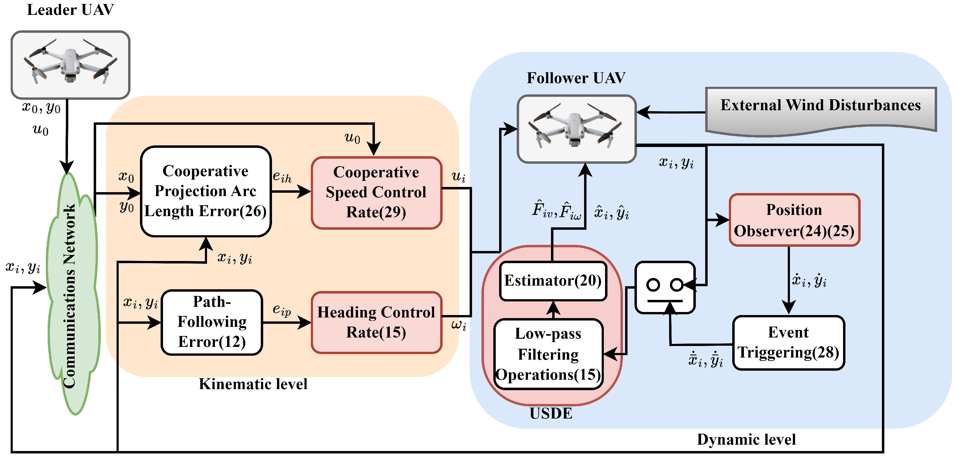
The cooperative following control strategy for UAV clusters with spatio-temporal decoupling characteristics is explored in this section. To mitigate the stringent requirement of the time domain in the traditional trajectory tracking process, both the heading controller and the velocity controller are designed based on the LMI theory to fulfill the tasks at the prescribed spatial and temporal levels, with the projected arc length integrated into the velocity controller. The USDE is introduced into each controller to estimate the system perturbation, and to enhance the system’s perturbation resistance through the amalgamation of an event-triggered mechanism with a position estimator. In this paper, the overall system control block diagram is shown in Figure 1. It illustrates the overall cooperative path-following architecture for the leader–follower UAV system. The leader generates the desired trajectory and reference velocity, while each follower tracks this information through two coordinated control loops: a spatial loop that corrects position and heading errors e p , i , e θ , i , and a temporal loop that adjusts velocity errors ( e h , i ) to maintain formation consistency. A USDE module estimates external disturbances and feeds them forward to enhance robustness, and an observer with a dynamic ETM provides intermittent state updates from neighboring UAVs to reduce communication load. The signal arrows in Figure 1 represent the main information flow—from reference generation, error computation, and disturbance estimation to control output—corresponding respectively to Section 3.1, Section 3.2, Section 3.3 and Section 3.4 for detailed explanation.

3.1. Heading Controller Design

In this subsection the design of developing a high real-time UAV heading controller with spatio-temporal decoupling based on linear matrix inequality theory, specifically designing a UAV heading controller with spatio-temporal decoupling by introducing a composite bias consisting of path-following error and heading control bias.
It can be known that the path of the ith UAV is denoted as γ i = γ ( x i , y i ) , and the path-following error of the ith UAV is e i p = γ i γ 0 s i d = γ i s i d , where γ 0 = 0 , s i d is a user-defined constant, and there is a positive deviation between the evolved path and the desired path when s i d > 0 , and vice versa. γ i x , γ i y are called the first-order partial differentials of γ i , and γ i x x , γ i y y are the second-order partial differentials of γ i . Therefore, the formula for the desired heading angle θ i d of the ith UAV and the angular velocity θ ˙ i d are expressed by the following equations:
θ i d = arctan γ i x / γ i y , if γ i y 0 arctan γ i y / γ i x , if γ i x 0 ,
θ ˙ i d = γ i x γ i x y γ i y γ i x x u i cos θ i + ν i cos ψ i + γ i x γ i y y γ i y γ i x y u i sin θ i + ν i sin ψ i γ i 2 ,
where γ i 2 = γ i x 2 + γ i y 2 . Subsequently, the heading controlling deviation is defined as e i θ = θ i θ i d . Especially, the virtual leader UAV fulfills e 0 θ = 0 . Based on (5), by taking the derivatives of γ i and e i θ , the path-following error dynamics of the ith UAV can be expressed as follows:
e ˙ i θ = ω i θ ˙ i d γ ˙ i = γ i u i sin e i θ + ν i sin ( ψ i θ i d ) ,
To enable the follower UAVs to approximate the preset path, a compound deviation consisting of path-following error and heading control deviation is introduced:
m i = e i θ + arctan ( k i 1 e i p ) ,
Next, using (5) and (12), the derivative of (13) with respect to time can be derived as follows:
m ˙ i = ω i θ ˙ i d + k i 1 γ i u i sin e i θ 1 + k i 1 e i p 2 + k i 1 γ i ν i sin ψ i θ i d 1 + k i 1 e i p 2 ,
For the subsequent derivation, (14) is reformulated as follows:
m ˙ i = ω i + F i ω θ ˙ i d , ν i , ψ i + h i 1 ,
where h i 1 = k i 1 γ i u i sin e i θ / 1 + k i 1 e i p 2 , F i θ ( θ ˙ i d , v i , ψ i ) = θ ˙ i d + k i 1 γ i sin ( ψ i θ i d ) / 1 + k i 1 e i p 2 are unknown terms containing wind disturbances, the heading control rate r that stabilizes the integrated deviation and achieves the spatial subgoal is as follows:
ω i = k i 1 1 + k i 1 e i p 2 γ i u i sin e i θ k i 2 m i F i ω .

3.2. Velocity Controller Design

To force the UAVs to align with the desired trajectory while maintaining a consistent forward speed, the following cooperation projected arc length errors of (17) below are specified for the UAV, which in turn ensures that the cooperative following control system circumvents the risk of collision within the range of the adjustable speed observation.
e i h t = i N i L a i j l i j t s i j l + b i l i 0 t s i 0 l ,
The design rule for the projected arc length is expressed as follows:
l i j ( t ) = x j ( t ) x i ( t ) 1 + γ i x γ i y 2 d x , if γ i y 0 l i j ( t ) = y j ( t ) y i ( t ) 1 + γ i y γ i x 2 d y , if γ i x 0 ,
l i 0 ( t ) = x 0 ( t ) x i ( t ) 1 + γ i x γ i y 2 d x , if γ i y 0 l i 0 ( t ) = y 0 ( t ) y i ( t ) 1 + γ i y γ i x 2 d y , if γ i x 0 ,
where l i j ( t ) and s i j l are the actual and expected projected arc lengths of the i-th UAV and the j-th UAV along the path of the desired curve. Let a i j denote the weight distribution between nodes i and j. If a i j = 1 , then a valid interaction exists; otherwise, a i j = 0 . b i = 1 denotes the information interaction between the following virtual leader UAV. Otherwise, b i = 0 . The triggered co-projected arc length error can be expressed as follows:
e ¯ i h t = j N i L a i j l ^ i j ( t k i ) s i j l + b i l ^ i 0 ( t k i ) s i 0 l ,
where
l ^ i j t k i = x ^ j i t k i x ^ i i t k i 1 + ( γ i x / γ i y ) 2 d x , if γ i y 0 l ^ i 0 t k i = x 0 ( t ) x ^ i i t k i 1 + ( γ i x / γ i y ) 2 d x , if γ i y 0 ,
We satisfy the speed co-regulator for the time task as follows:
u i = u 0 1 σ i tanh ( k i 2 e i h ) G ^ i ν .
where 0 < σ i 1 , k i 2 is an unspecified non-negative constant, and G ^ i v denotes the element of the i-th row of L + B 1 × Δ ^ 1 ν , Δ ^ 2 ν , Δ ^ N ν T .

3.3. USDE Design

In order to estimate the system disturbances caused by external wind disturbances, USDE is introduced in the above-designed heading and speed controllers, respectively, with the following design rules: The derivative of the unknown term F i θ ( θ ˙ i d , v i , ψ i ) is bounded, i.e., sup t 0 F ˙ i θ ƛ , where ƛ is a nonnegative constant. To estimate F i ω ( θ ˙ i d , v i , ψ i ) , apply low-pass filtering operations to m i , ω i and h i 1 , described as follows:
ς i ω m ˙ i f + m i f = m i , m i f 0 = 0 ς i ω ω ˙ i f + ω i f = ω i , ω i f 0 = 0 ς i ω h ˙ i 1 f + h i 1 f = h i 1 , h i 1 f 0 = 0 ,
where ς i ω > 0 is the filtering parameter, m i f , ω i f and h i 1 f are the filtering variables.
Definition 3.
One can define the observation system (15) and the filtering state (23), with the auxiliary variable ξ i designed as ξ i = m i m i f ς i ω ω i f h i 1 f F i ω . Moreover, it is bounded and converges exponentially for fixed ς i ω > 0 with lim κ i ω > 0 lim t { m i m i f ς i ω ω i f h i 1 f F i ω } = 0 . It can be shown that m i m i f ς i ω ω i f h i 1 f F i ω is an invariant manifold of ς i ω 0 .
According to the above theory, the observed F ^ i ω for the designed USDE is F ^ i ω = ( m i m i f ) / ς i ω ω i f h i 1 f . Where F ^ i ω denotes the estimated value of F i ω . Furthermore, the estimation error is defined as e i ω = F i ω F ^ i ω . If Definition 2 holds, then the bounded range of the estimation error e i ω is | e i ω ( t ) | e i ω 2 ( 0 ) e t / κ i ω + ς i ω 2 ƛ i ω 2 1 / 2 . Thus, F ^ i ω F i ω when ς i ω 0 and ƛ i ω 0 .
Inspired by the above, the derivation of (17) yields the following:
e ˙ i h ( t ) = j N i L a i j x ˙ i t 1 + γ i x / γ i y 2 x ˙ j t 1 + γ j x / γ j y 2 + b i x ˙ i t 1 + γ i x / γ i y 2 x ˙ 0 t 1 + γ 0 x / γ 0 y 2 ,
Substituting (5) into (24) yields the following:
e ˙ i h ( t ) = j N i L a i j 1 + γ i x / γ i y 2 u i cos θ i x ˙ j t 1 + γ j x / γ j y 2 + b i 1 + γ i x / γ i y 2 u i cos θ i u 0 cos θ 1 + γ 0 x / γ 0 y 2 + j N i L a i j + b i 1 + γ i x / γ i y 2 v i cos ψ i ,
For the next derivation, (25) is rewritten as e ˙ i h = h i 2 + F i v ( v i , ψ i ) , where h i 2 = j N i L a i j 1 + γ i x γ i y 2 u i cos θ i x ˙ j ( t ) 1 + γ j x γ j y 2 + b i 1 + γ i x γ i γ 2 u i cos θ i 1 + γ o x γ o y 2 u 0 cos θ 0 .
Similar to the previous USDE design, the implementation of low-pass filtering operations on e i h and h i 2 , described as follows:
ς i v e ˙ i h f + e i h f = e i h , e i h f 0 = 0 ς i v h i 2 f + h i 2 f = h i 2 , h i 2 f 0 = 0 .
where ς i v > 0 denotes the filtering parameter, e i h f and h i 2 f are the filtering variables. Therefore, in accordance with the previous rule of ideal invariant manifolds, the estimated USDE of F i v can be designed as F ^ i v = e i h e i h f / ς i v h i 2 f . Where F ^ i v signifies the estimated value of F i v .
For the USDE error dynamics F ^ i v , the boundedness of e i v = F i v F ^ i v can be deduced by e i v t e i v 2 0 e t / ς i v + ς i v 2 ƛ i v 2 1 / 2 . It is remarkable that F ^ i v F i v if and only if ς i v 0 and ƛ i v 0 .
Proof. 
Construct a Lyapunov candidate function for V i e = e i v 2 / 2 , then the time derivative of V i e yields V ˙ i e = e i v e ˙ i v = e i v 2 / ς i v + e i v F ˙ i v e i v 2 / ς i v + e i v 2 / 2 ς i v + ς i v F ˙ i v 2 / 2 V i e / ς i v + ς i v ƛ ^ i v 2 / 2 . By solving V ˙ i e and using Young’s inequality, one can obtain that, then one obtains e i v ( t ) e i v 2 ( 0 ) e t / ς i v + ς i v 2 ƛ i v 2 1 / 2 . Hence it can be shown that the above inference holds. □

3.4. Position Observer Design

To deal with unknown terms caused by wind disturbances and to alleviate the sampling burden, a nonperiodic event-triggered criterion is proposed, which includes a position observer to minimize data transmission loads and facilitate disturbance observations and controller updates in a nonperiodic time series, rather than at prescribed moments. The designed position observer time sequence rule is indicated as follows:
t 1 j = 0 , t k j = Δ arg min q N t t q j t t q j ,
Subsequently, the design guidelines for the position observer are designed as follows:
x ^ i i t = x i t x ^ j i t = x ¯ j ( t k j ) + t t k j x ¯ ˙ j ( t k j ) if γ i y 0 ,
y ^ i i t = y i t y ^ j i t = y ¯ j t k j + t t k j y ¯ ˙ j t k j if γ i x 0 ,
where arg min { · } denotes the minimum set of parameters, while x ^ i i ( t ) , y ^ i i ( t ) and x ^ j i ( t ) , y ^ j i ( t ) denote the position estimates of the ith UAV and the jth UAV, respectively, at moment t. x ¯ j ( t k j ) , y ¯ j ( t k j ) and x ¯ ˙ j ( t k j ) , y ¯ ˙ j ( t k j ) denote the received trigger position of the jth UAV at moment t k j and its derivatives. In the case of γ i y 0 , the triggered co-projected arc length error can be expressed as follows:
e ¯ i h t = j N i L a i j l ^ i j t k i s i j l + b i l ^ i 0 t k i s i 0 l ,
where
l ^ i j t k i = x ^ j i t k i x ^ i i t k i 1 + ( γ i x / γ i y ) 2 d x , if γ i y 0 l ^ i 0 t k i = x 0 ( t ) x ^ i i t k i 1 + ( γ i x / γ i y ) 2 d x , if γ i y 0 ,
Denote e ¯ i h ( t ) as e ¯ i h ( t ) = e i h ( t ) + e i h ι ( t ) + c i ( t ) , where c i ( t ) is defined as the prediction error and e i h ι ( t ) is defined as the trigger error with c i ( t ) = j N i L a i j x ^ j i ( t ) x j ( t ) 1 + γ i x γ i y 2 d x and e i h ι ( t ) = e ¯ i h ( t ) e i h δ ( t ) , where e i h δ ( t ) = j N i L a i j [ l ^ i j ( t ) s i j l ] + b i [ l ^ i 0 ( t ) s i 0 l ] .
To reduce the data transmission load and ensure observation accuracy, transmission intervals are specified through the implementation of an event-triggered mechanism, which allows for perturbed observations and controller updates to occur in a nonperiodic time series rather than at a defined moment. For the i th UAV, if inf k { t k + 1 i t k i } > 0 , the closed-loop system will not exhibit Zeno behavior, indicating that the system will not undergo an infinite number of event triggers within a finite time, with the following event-triggered criteria:
x ¯ i t = x i t k i , t t k i , t k + 1 i x ¯ ˙ i t = x ˙ i t k i , t t k i , t k + 1 i t k + 1 i = inf t : t > t k i e i h ι t 2 τ i 2 e i h κ t 2 μ i .
where inf { · } denotes the infimum boundary; 0 < τ i < 1 denotes the event triggering constant; μ i is the trigger positive threshold; and t k + 1 i denotes the next triggering moment. Upon the violation of the event triggering criterion (32), the event will be activated immediately; the ith UAV will update and send its sampled position information x ¯ i ( t ) and x ¯ ˙ i t to the neighboring UAVs only at the moment of t k + 1 i , otherwise x ¯ i ( t ) , x ¯ ˙ i t will keep the sampled values at the moment of t k i .

4. Stability Analysis

In this section, the ISS principle is used to analyze the boundedness of the whole system, including the boundedness of the heading controller, the velocity controller, and the position observer. The convergence of the heading and speed controllers ensures the realization of the UAS path following rate in both time and space tasks, and the convergence of the position observer proves that the system is able to achieve better disturbance compensation while avoiding much resource waste.

4.1. Heading Controller Feasibility Analysis

To demonstrate that the control purpose of the spatial mission can be achieved, the heading and path deviations are analyzed for convergence. Substituting (16) into (14) gives m ˙ i = k i 2 m i + e i ω . Revisiting Definition 2 ensures that m i is bounded. It is worth noting that when e i ω 0 , m i converges asymptotically with e i θ = arctan k i 1 e i p . The derivative of e i p is expressed as follows:
e ˙ i p = γ i u i sin arctan ( k i 1 γ i ) + γ i v i sin ψ i θ i d = γ i u i k i 1 γ i / 1 + k i 1 γ i 2 + γ i v i sin ψ i θ i d ,
Consider a Lyapunov function for V 1 = 1 / 2 e i p 2 . The derivative is extracted to give the following:
V ˙ 1 = γ i u i k i 1 e i p 2 / 1 + k i 1 e i p 2 + γ i e i p v i sin ψ i θ i d k i 1 u i e i p 2 γ i / 1 + k i 1 e i p 2 + γ i e i p v i sin ψ i θ i d ,
Since e i p / 1 + k i 1 e i p 2 v i sin ψ i θ i d / k i 1 u i κ , this implies the following:
V ˙ 1 1 κ k i 1 u i e i p 2 γ i / 1 + k i 1 e i p 2 ,
where 0 < κ < 1 . Consequently, it is possible to obtain the following:
e i p max ϖ i 1 γ i ( 0 ) , t , φ i 1 v i w sin ( ψ i θ i d ) .
where ϖ i 1 is a K L function and φ i 1 s = s s k i 1 v i κ k i 1 v i κ . Therefore, it can be shown that the control objective of the spatial mission (8) is achieved.

4.2. Velocity Controller Feasibility Analysis

Inspired by the above verification theory, further derivation of (17) is next derived as follows:
e ˙ i h = j N i L a i j 1 + γ i x + γ i y 2 u i cos θ i + v i cos ψ i 1 + γ j x + γ j y 2 u j cos θ j + v j cos ψ j + b i 1 + γ i x + γ i y 2 u i cos θ i + v i cos ψ i 1 + γ 0 x + γ 0 y 2 u 0 cos θ 0 ,
According to Definition 1, since the virtual leader UAV always moves along the pre-evolutionary path, the heading angle satisfies θ 0 = arctan γ 0 x / γ o y , and thus (37) can be rewritten as follows:
e ˙ i h = j N i L a i j γ i / γ i y u i cos θ i d + e i θ + v i cos ψ i γ j / γ j y u j cos θ j d + e j θ + v j cos ψ j + b i γ i / γ i y u i cos θ i d + e i θ + v i cos ψ i u 0 ,
Define E H = e 1 h , e 2 h , , e N h T with the following:
Υ = u 1 cos ( θ 1 d + e 1 θ ) γ 1 / γ 1 y + v 1 cos ψ 1 γ 1 / γ 1 y u 0 u 2 cos ( θ 2 d + e 3 θ ) γ 2 / γ 2 y + v 2 cos ψ 2 γ 2 / γ 2 y u 0 u N cos ( θ N d + e N θ ) γ N / γ N y + v N cos ψ N γ N / γ N y u 0 ,
Next, the differential of E H is modified as follows:
E ˙ H = L + B Υ ,
According to (12), cos e i θ + θ i d can be expressed as follows:
cos θ i d + e i θ = cos e i θ γ i y / γ i + sin e i θ γ i x / γ i = γ i y / γ i + cos e i θ 1 γ i y / γ i + sin e i θ γ i x / γ i ,
Substituting (41) into (40) yields the following:
E ˙ H = ( L + B ) u 1 + ι 1 u 0 + v 1 cos ψ 1 γ 1 / γ 1 y u 2 + ι 2 u 0 + v 2 cos ψ 2 γ 2 / γ 2 y u N + ι N u 0 + v N cos ψ N γ N / γ N y ,
where ι i = 2 u i sin e i θ e i θ 2 2 sin e i θ e i θ 2 2 + γ i x γ i x γ i y γ i y cos e i θ e i θ 2 2 . Then by Definition 2, substituting (22) into (42), one obtains the following:
E ˙ H = L + B u 0 ζ 1 tanh ( k 12 e 1 h ) u 0 ζ 2 tanh ( k 22 e 2 h ) u 0 ζ N tanh ( k N 2 e N h ) + L + B ι 1 ι 2 ι M + e 1 v e 2 v e N v .
Since ι i and e i v are bounded, according to the above Definition 2 and by revisiting the boundedness of e i v , E H ends up being bounded in agreement with e i θ and e i v . Thus, it can be inferred that e i h can converge to a limited region near the origin, and in the absence of uncertainty, gives lim t u i u 0 = ζ i tanh ( k i 3 e ¯ i h ) ζ i = Δ ε 4 , i.e., implying that the temporal mission (9) is implemented.

4.3. Position Observer Feasibility Analysis

Definition 4.
Define the position error of the UAV as follows:
e i x = x i x ^ i ,
where x i denotes the UAV true position, x ^ i denotes the UAV estimated position, and e i x is the position estimation error.
Let the UAV be subjected to an external wind speed perturbation v i . The actual dynamic equations of the UAV are x ˙ i = u i + v i , and the estimating equation for the observer is x ^ ˙ i = u i + v ^ i , where v ^ i is the perturbation estimated by USDE.
Definition 5.
Define the dynamic equation for the error e i x as follows:
e ˙ i x = x ˙ i x ^ ˙ i = v i v ^ i ,
Design the Lyapunov function as V = 1 / 2 ( e i x ) T e i x , derivation of V gives V ˙ = ( e i x ) T e ˙ i x = ( e i x ) T ( v i v ^ i ) . Consider the USDE estimation error e v = v i v ^ i such that e ˙ v = λ e v , where λ is a non-negative constant used to ensure error convergence. Therefore, it can be obtained that V ˙ = ( e i x ) T e v . According to Young’s inequality V ˙ λ V , by Lyapunov’s theorem the system is asymptotically stable, i.e., the position estimation error e i x converges to zero.
Next, to demonstrate that the proposed event-triggering mechanism does not exhibit Zeno behavior, it is preceded by the following theorem.
Theorem 1.
Considering the system following error (17) as well as the control input (22), for the i th UAV, it can be calculated that a positive lower bound T i exists on the interval between any two consecutive triggering times t k + 1 i t k i , which satisfies:
t i = Δ min { t k + 1 i t k i } T i ,
Since e i h ( t ) is bounded and e i h δ ( t ) = e i l ( t ) + c i , it follows from (43) that c i is a sufficiently small quantity. If the UAV trigger time is close to the present moment, then e i h δ ˙ ( t ) i h holds, where i h is a positive constant. It follows that e i h ι ( t k i ) = 0 and lim t t k + 1 i e i h ι ( t ) = e i h δ ƛ i h , where ƛ i h is a non-negative constant. The lower bound of the trigger interval is determined by (46), so confirming Theorem 1. According to the definition of the event-triggering criterion, it is obvious that the designed event-triggered control scheme can effectively avoid the occurrence of Zeno behavior.
The above theory proves that the various parts of the control system designed in this paper can work in a coordinated and stable manner. The algorithm flow of the entire control system is given in Table 1 below.

5. Simulation Results and Analysis

In this section, based on a laboratory-grade quadcopter UAV platform, we constructed a system comprising one virtual leader and four follower UAVs numbered N = 1–4 to achieve cooperative path-following tasks. The leader UAV’s flight path is generated by its own dynamic model, i.e., it moves according to the system’s natural dynamics (described by the discretized system matrix). All experiments in this paper were conducted using Matlab/Simulink software. Both “process disturbances” (simulating gusts) and “measurement noise” (simulating sensor errors) were incorporated into the simulations. By employing the LMI toolbox (setlmis, lmivar, lmiterm) to solve for design parameters, the complex controller design problem was transformed into an efficiently solvable convex optimization problem. Subsequently, an H robust controller was designed to address excessive tracking errors under disturbances, enabling the controller to actively suppress disturbances.
To ensure all followers can ultimately track the leader, a directed spanning tree with the leader as its root node transmits the leader’s status information directly or indirectly to each follower via the communication network. This approach simplifies the command chain in the star topology, concentrating task coordination logic at the leader node for easier management and debugging. The communication topology is illustrated in Figure 2.
The closed-loop system and the associated parameter matrix are as follows:
L + B = 5 2 2 0 2 7 2 2 2 2 4 0 0 2 0 2 .
Consider the external wind disturbances [ v i , ψ i ] suffered by each UAV as [ v 1 , ψ 1 ] = [ arctan ( t / 100 ) / 2 , ( π / 7 ) sin ( π t / 300 ) ] , [ v 2 , ψ 2 ] = [ cos ( π t / 100 ) , ( π / 4 ) cos ( π t / 50 ) ] , [ v 3 , ψ 3 ] = [ 2 arctan ( t / 25 ) 0.001 t , ( π / 4 ) sin ( π t / 50 ) ] , [ v 4 , ψ 4 ] = [ sin ( π t / 150 ) , ( π / 5 ) cos ( π t / 50 ) ] . The initial conditions for the position and heading of the pilot and follower are set to [ x 0 , y 0 , θ 0 ] = [ 10 , 10 , 0 ] , [ x 1 , y 1 , θ 1 ] = [ 3 , 3 , 1.6 ] , [ x 2 , y 2 , θ 2 ] = [ 4 , 1 , 1.3 ] , [ x 3 , y 3 , θ 3 ] = [ 0 , 2 , 0.5 ] , [ x 4 , y 4 , θ 4 ] = [ 4 , 8 , 0 ] respectively.
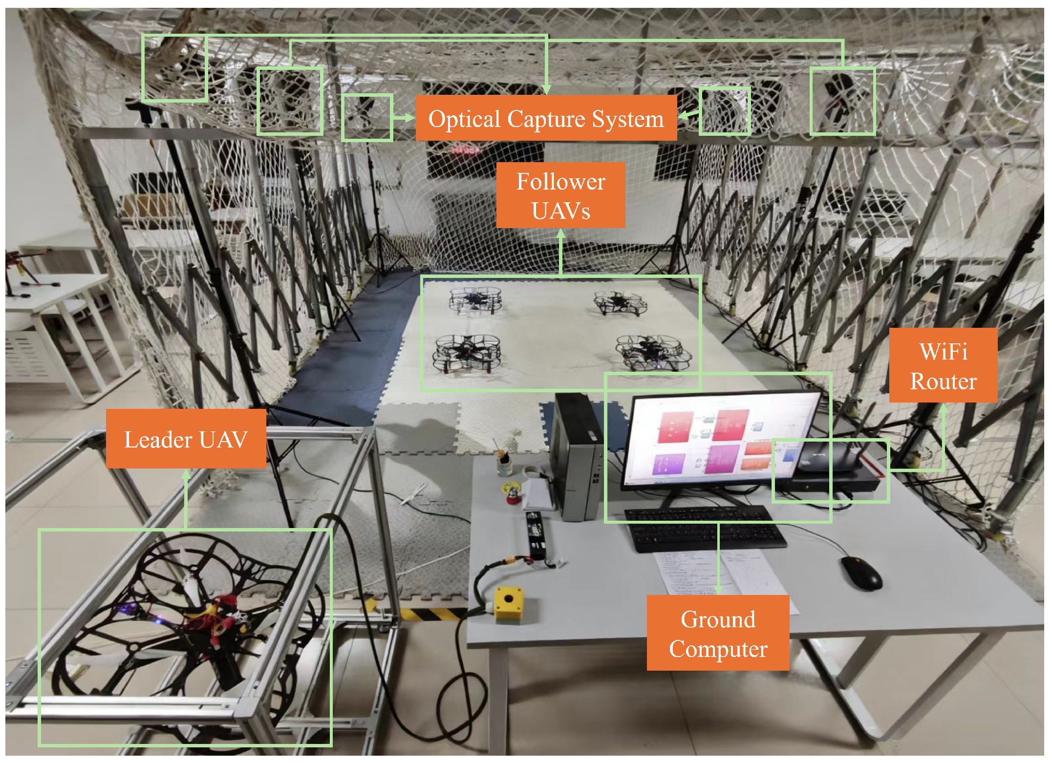
To validate the proposed collaborative control strategy, a small-scale “air-ground integrated” experimental platform was constructed, as shown in Figure 3. The leader aircraft was mounted on a 360° rotatable active pylon and powered by a constant-voltage power supply, enabling it to complete sustained hovering and attitude perturbation tests indoors. The four followers, completely independent of external power supply, took off using their own batteries, forming the “air ring” (Figure 4) around the leader aircraft to form a dynamic five-aircraft formation.
The ground station retains only one edge computing node and one industrial Wi-Fi 6 router, responsible for data aggregation and task injection. The aerial fleet comprises five quadcopters, each equipped with one STM32H7 flight controller (STMicroelectronics, Geneva, Switzerland) core board running the proposed distributed algorithm; a 40 A quad-in-one ESC board for 200 Hz closed-loop motor speed control; and an ESP32-S3 Wi-Fi module (Espressif Systems, Shanghai, China) operating on the 5 GHz band, responsible for receiving “ellipse parameter packets” from the ground and transmitting its own status back.
The positioning system abandons traditional GPS in favor of an external capture array comprising six Vicon infrared cameras. The array uniquely identifies each drone via reflective markers, outputting 6-DoF pose data at 120 Hz with ±5 mm accuracy. This data is aggregated via Gigabit Ethernet to the NUC. After fitting the implicit elliptical trajectory in real-time, the NUC packages only six floating-point values—“ellipse center, major/minor axes, and deflection angle”—and unicasts them at 20 Hz to the five drones. Each drone then uses its onboard IMU and optical flow sensor to locally compute relative pose and update its controller. This creates a star-shaped “ground-to-air” information flow instead of a mesh “drone-to-drone” network, reducing bandwidth requirements and eliminating inter-drone clock synchronization challenges.
Communication logic employs a “chain-triggered” topology: Lead drone → Follower 1 → Follower 2 → Follower 3 → Follower 4 → Follower 1. Each drone subscribes only to broadcast packets from its immediate predecessor to generate its own collaborative correction. Computational load and memory usage scale linearly with formation size, making it highly compatible with current hardware. The control inputs as well as the controller-related parameters are shown in Table 2.
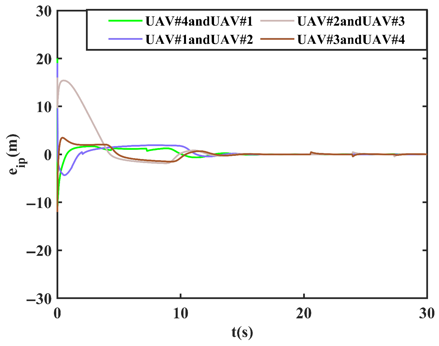
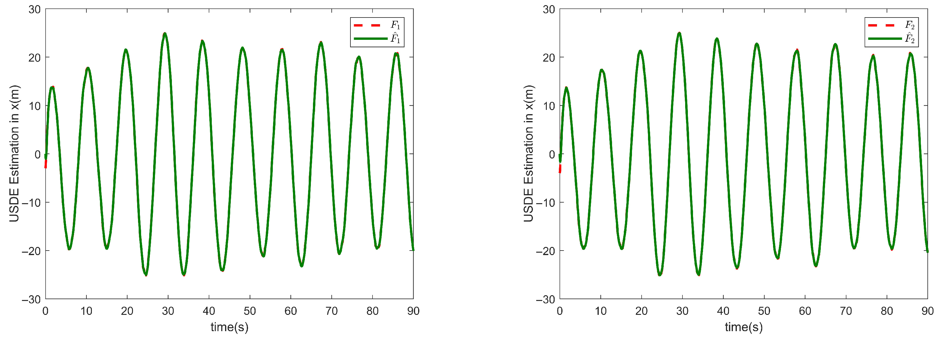
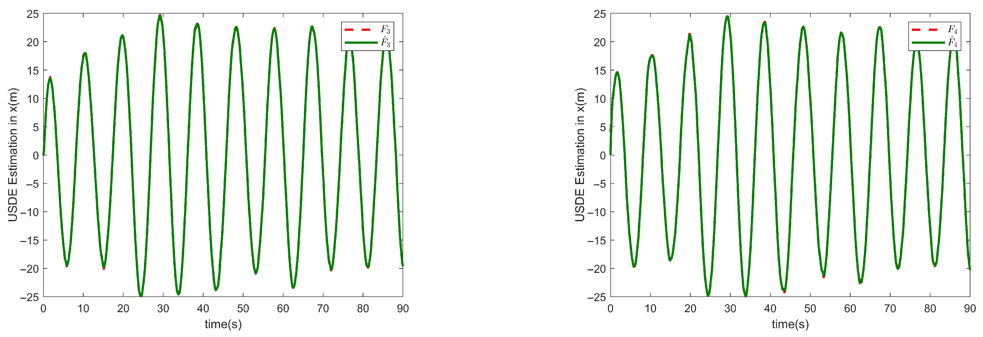
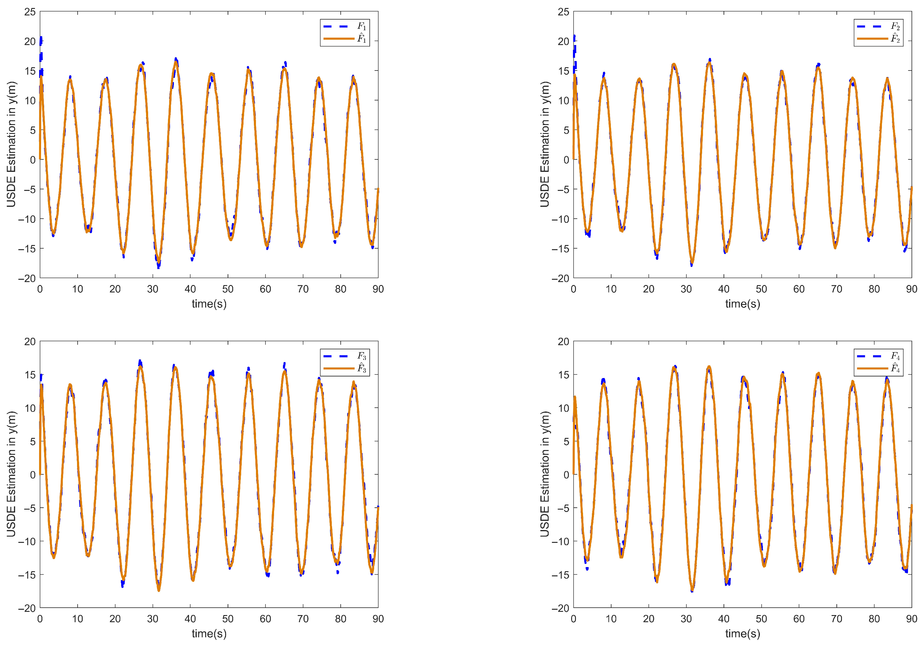
To verify that the control task in this paper can be realized, the simulation results are shown in Figure 5, Figure 6 and Figure 7. The cooperative projected arc-length errors among the four follower UAVs are shown in Figure 5, with the final error converging to near zero, thus proving the realization of the temporal and spatial tasks in the previous section. While Figure 6 and Figure 7 show the estimated state of the four follower UAVs in the x and y directions, respectively, compared to the original state, thanks to the combination of the designed position observer and USDE, which improves the system’s anti-interference capability and can effectively compensate for unknown perturbations, thus verifying the effectiveness of the designed event-triggered-based position observer.
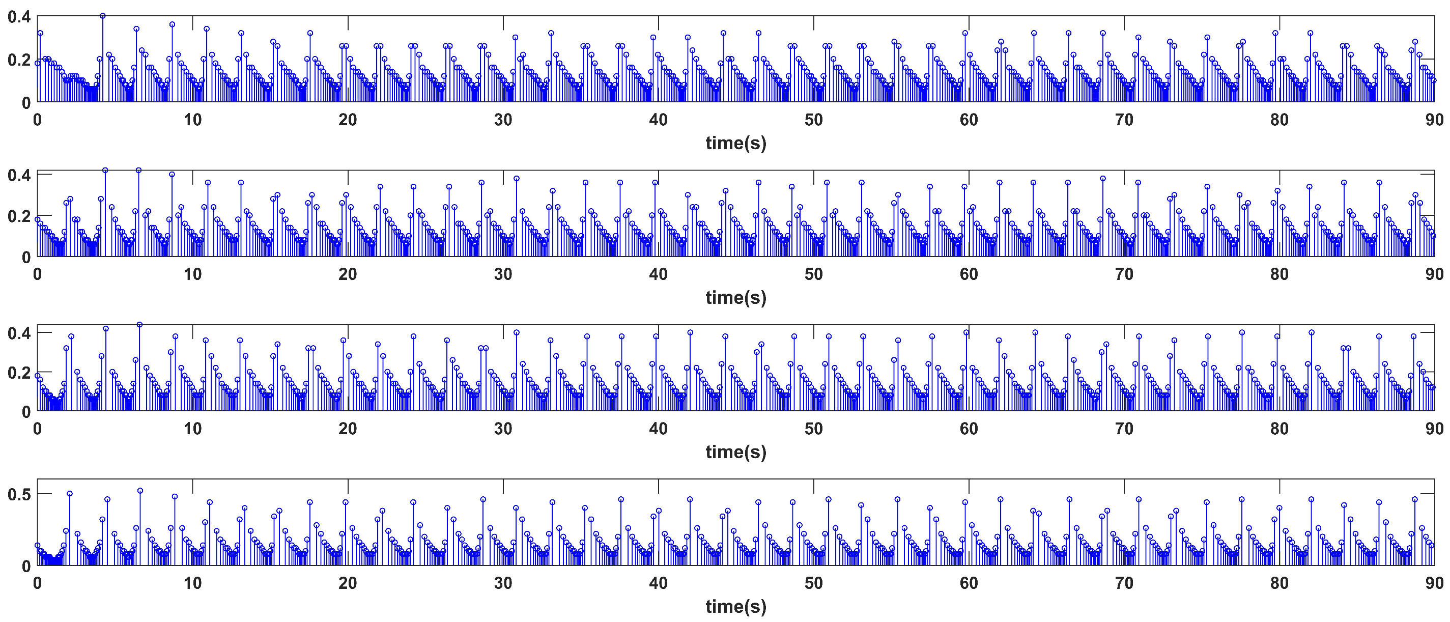
The triggering moments of the system are shown in Figure 8, with the horizontal axis indicating the moment of trigger occurrence and the vertical axis indicating the duration of this trigger. The four follower control signals are updated exclusively when the trigger condition is satisfied. The number of event triggers in the time interval [0, 10 s] are 64, 65, 65, and 69, indicating that no Zeno behavior occurs. The event trigger times for each UAV are shown in Table 3. Therefore, the designed trigger conditions can effectively reduce the demand for communication resources and improve the utilization efficiency of network resources.
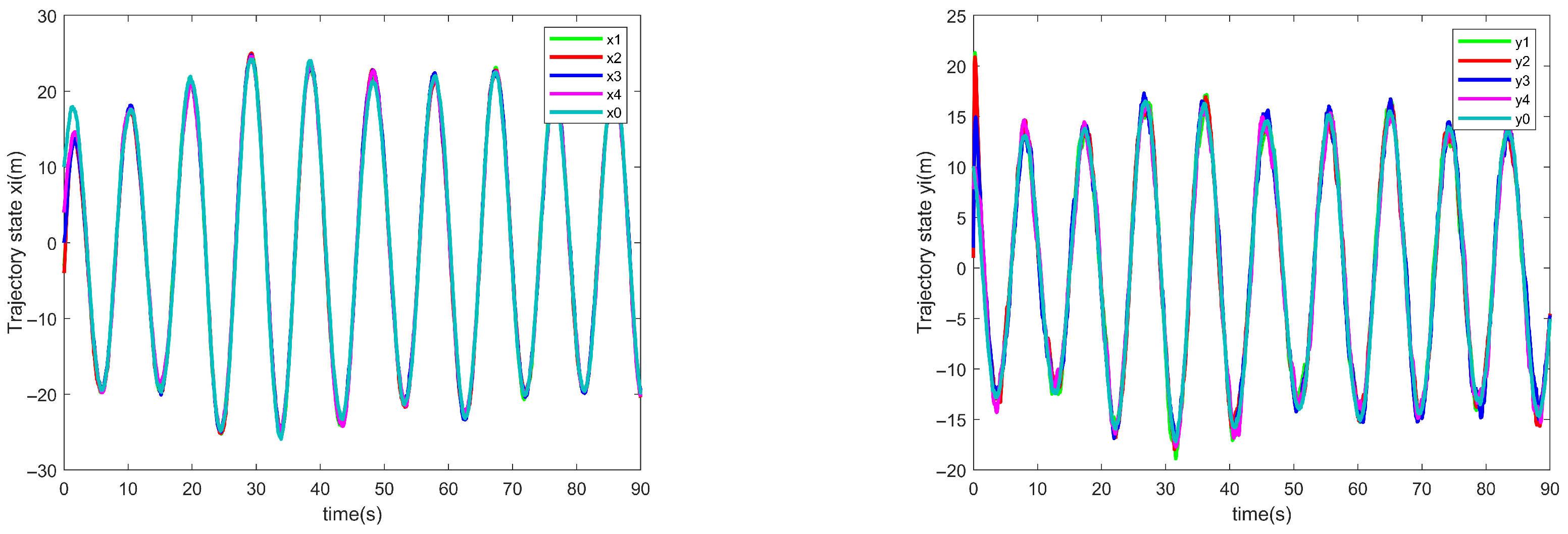
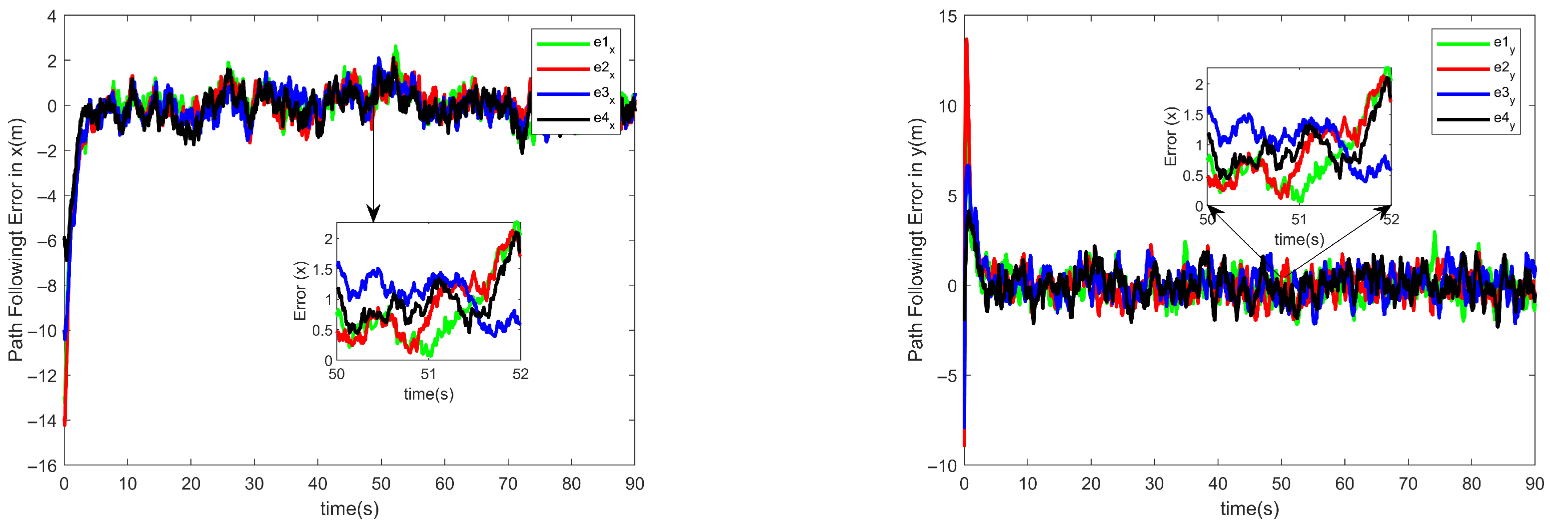
Figure 9 illustrates the path-following effect of the follower UAVs, and it can be seen that the four follower UAVs finally realized the parallel following task along the route planned by the virtual leader. While Figure 10 demonstrates that the proposed control algorithm makes the system maintain good following performance despite external disturbances. The path-following errors of the four follower UAVs converge asymptotically to zero, successfully completing the formation convergence task to maintain cooperative consistency. Figure 11 visually illustrates the linear and angular velocities of each follower. It reveals that under actual disturbances, their dynamic stability during the convergence process exhibits small-scale fluctuations within the range [−1, 1].
The aforementioned experiments demonstrate that the path tracking error for all UAVs converges to within ± 0.3 m within 30 s, validating the proposed controller’s robustness under complex disturbances. The collaborative projection arc length error ultimately converges to ± 0.5 m, indicating that UAVs can fly stably in an approximately equidistant manner to accomplish spatiotemporal collaborative tasks. Integrating the USDE position observer significantly enhances state estimation accuracy, with estimation errors in both x/y directions below 0.2 m, demonstrating excellent adaptability to unknown wind disturbances. The event-triggered mechanism maintained an average trigger interval of approximately 0.15 s, reducing communication frequency by about 70% compared to traditional periodic sampling (20 Hz). No Zeno behavior was observed. Compared to commonly used periodic communication and disturbance-free compensation methods in the literature, this approach demonstrates superior overall performance in convergence speed, communication load, and robustness (see Table 4 for details).

6. Conclusions and Outlook

A cooperative path-following control scheme is developed for multiple UAVs under external wind disturbances. By leveraging spatio-temporal decoupling and LMI theory, the proposed method circumvents the temporal rigidity of traditional trajectory tracking. A projection arc-length method ensures stable path convergence and uniform formation spacing. System resilience is enhanced by a USDE for disturbance rejection, while an event-triggered position observer reduces network resource consumption. The synergistic integration of these components yields a highly stable and efficient control system, with its effectiveness validated by extensive simulations.
Although this study successfully demonstrated the effectiveness of the proposed control framework via simulation, we acknowledge its current limitations. The main limitation is that all tests were conducted in an idealized simulation environment, which does not fully capture the complex challenges of real-world deployment, such as sensor noise, communication delays, and packet loss. Consequently, the current system has only been validated in a static, obstacle-free environment, and its robustness against dynamic obstacles or under unpredictable communication conditions remains untested. Furthermore, the computational feasibility of implementing the algorithm in real-time on resource-constrained onboard hardware requires further evaluation.
Based on these limitations, our future work will focus on two primary objectives to transition the system from theoretical validation to a field-ready solution. First, we plan to conduct experimental validation on a physical multi-UAV testbed and integrate advanced dynamic obstacle avoidance capabilities to enhance the system’s robustness and safety in real, complex environments. Second, we will work on extending the framework to support larger-scale UAV swarm operations. The next step is to develop decentralized cooperation strategies that fully leverage the efficiency of the event-triggered communication mechanism, enabling the swarm to collaborate effectively on complex tasks and thereby unlocking the full potential of our cooperative framework.
Author Contributions

J.Y.: thesis writing and code writing; K.Y.: review and editing and ideas; B.W.: algorithm testing and data curation; D.Z.: formulation or evolution of overarching research goals and aims and methodology; T.L.: review and editing and visualization; C.S.: review and editing and supervision. All authors have read and agreed to the published version of the manuscript.

Funding

This work was supported in part by the Fundamental Research Program of Shanxi Province under Grant (2023030 21211150), in part by the National Key Laboratory of Electromagnetic Space Security (JCKY2025250C004), and in part by the Tianjin Renai College and Tianjin University Teacher Development Fund Cooperation Project under Grant (FZ231002).

Data Availability Statement

The original contributions presented in this study are included in the article. Further inquiries can be directed to the corresponding author.

Conflicts of Interest

The authors declare that they have no known competing financial interests or personal relationships that could have appeared to influence the work reported in this paper.

References

  1. Gromada, K.; Siemiątkowska, B.; Stecz, W.; Płochocki, K.; Woźniak, K. Real-Time Object Detection and Classification by UAV Equipped with SAR. Sensors 2022, 22, 2068. [Google Scholar] [CrossRef]
  2. Chen, Y.; Wang, N.; Hong, H.; Liu, Z.; Miao, Y. Research on Cooperative Surveillance Method of Multi Unmanned Platforms for Regional Surveillance. In Proceedings of the 2024 9th International Conference on Intelligent Computing and Signal Processing (ICSP), Xi’an, China, 19–21 April 2024; pp. 244–250. [Google Scholar] [CrossRef]
  3. Aljohani, M.; Mukkamala, R.; Olariu, S. Autonomous Strike UAVs in Support of Homeland Security Missions: Challenges and Preliminary Solutions. IEEE Access 2024, 12, 90979–90996. [Google Scholar] [CrossRef]
  4. Zhang, C.; Zhou, W.; Qin, W.; Tang, W. A novel UAV path planning approach: Heuristic crossing search and rescue optimization algorithm. Expert Syst. Appl. 2023, 215, 119243. [Google Scholar] [CrossRef]
  5. Ryu, J.H. UAS-based real-time water quality monitoring, sampling, and visualization platform (UASWQP). HardwareX 2022, 11, e00277. [Google Scholar] [CrossRef]
  6. Maier, K.; Nascetti, A.; Li, F.; Ward, P.; Rosqvist, G. Direct photogrammetry with multispectral imagery for UAV-based snow depth estimation. ISPRS J. Photogramm. Remote Sens. 2022, 186, 1–18. [Google Scholar] [CrossRef]
  7. Ma, C.; Wen, X.; Yang, J.; Chao, T. UAV Trajectory Tracking Based on Model Predictive Control. Adv. Guid. Navig. Control 2025, 1354, 269–277. [Google Scholar] [CrossRef]
  8. Yang, Z.; Luo, D.; Guo, Z.; Xu, Y. Adaptive predefined-time path-following control for fixed-wing UAV formations with prescribed performance. Appl. Math. Model. 2025, 147, 116173. [Google Scholar] [CrossRef]
  9. Radoglou-Grammatikis, P.; Sarigiannidis, P.; Lagkas, T.; Moscholios, I. A compilation of UAV applications for precision agriculture. Comput. Netw. 2020, 172, 107148. [Google Scholar] [CrossRef]
  10. Lambert, A.; Hamel, T.; Le Fort-Piat, N. A safe and robust path following planner for wheeled robots. In Proceedings of the 1998 IEEE/RSJ International Conference on Intelligent Robots and Systems. Innovations in Theory, Practice and Applications (Cat. No.98CH36190), Victoria, BC, Canada, 13–17 October 1998; pp. 600–605. [Google Scholar] [CrossRef]
  11. Wang, Y.; Wang, X.; Yu, Y.; Hu, W.; Shen, L. Collision Free Curved Path Following for Small Fixed-Wing UAVs. In Proceedings of the 2021 40th Chinese Control Conference (CCC), Shanghai, China, 26–28 July 2021; pp. 439–444. [Google Scholar] [CrossRef]
  12. Chen, H.; Cong, Y.; Wang, X.; Xu, X.; Shen, L. Coordinated Path-Following Control of Fixed-Wing Unmanned Aerial Vehicles. IEEE Trans. Syst. Man. Cybern. Syst. 2022, 52, 2540–2554. [Google Scholar] [CrossRef]
  13. Chen, P.; Zhang, G.; Li, J.; Chang, Z.; Yan, Q. Path-Following Control of Small Fixed-Wing UAVs under Wind Disturbance. Drones 2023, 7, 253. [Google Scholar] [CrossRef]
  14. Pham, T.V.; Nguyen, T.D. Path-Following Formation of Fixed-Wing UAVs under Communication Delay: A Vector Field Approach. Drones 2024, 8, 237. [Google Scholar] [CrossRef]
  15. Kim, S.; Jung, D. Adaptive Path Guidance Law for a Small Fixed-Wing UAS with Bounded Bank Angle. Drones 2025, 9, 180. [Google Scholar] [CrossRef]
  16. Yang, K.; Kang, Y.; Sukkarieh, S. Adaptive nonlinear model predictive path-following control for a fixed-wing unmanned aerial vehicle. Int. J. Control Autom. Syst. 2013, 11, 65–74. [Google Scholar] [CrossRef]
  17. Xue, J.; Wu, M.; Yang, Z. Path Following Control for Unmanned Aerial Vehicle Based on Carrot Chasing Algorithm and PLOS. In Proceedings of the 2020 IEEE International Conference on Artificial Intelligence and Information Systems (ICAIIS), Dalian, China, 20–22 March 2020; pp. 571–576. [Google Scholar] [CrossRef]
  18. Yi, B.; Ortega, R.; Manchester, I.R.; Siguerdidjane, H. Path following of a class of underactuated mechanical systems via immersion and invariance-based orbital stabilization. Int. J. Robust Nonlinear Control 2020, 30, 8521–8544. [Google Scholar] [CrossRef]
  19. Ahmed, Z.; Xiong, X. Adaptive Impedance Control of Multirotor UAV for Accurate and Robust Path Following. Machines 2024, 12, 868. [Google Scholar] [CrossRef]
  20. Sujit, P.B.; Saripalli, S.; Sousa, J.B. Unmanned aerial vehicle path following: A survey and analysis of algorithms for fixed-wing unmanned aerial vehicless. IEEE Control Syst. Mag. 2014, 34, 42–59. [Google Scholar] [CrossRef]
  21. Zhang, Z.; He, C.; Chen, H.; Zhang, Y.; Wang, H.; Cai, Y.; Chen, L.; Li, H.; Lu, T. Small Fixed-Wing Unmanned Aerial Vehicle Path Following Under Low Altitude Wind Shear Disturbance. IEEE Trans. Intell. Transp. Syst. 2024, 25, 13991–14003. [Google Scholar] [CrossRef]
  22. Xu, L.; Wang, X.; He, P.; Wang, Y. Predictive Path-following Control for Tilt-quadrotor UAV based on Fully-actuated System Approaches. In Proceedings of the 2024 3rd Conference on Fully Actuated System Theory and Applications (FASTA), Shenzhen, China, 10–12 May 2024; pp. 1382–1387. [Google Scholar] [CrossRef]
  23. Ahmed, M.; Subbarao, K. Nonlinear 3-D trajectory guidance for unmanned aerial vehicles. In Proceedings of the 2010 11th International Conference on Control Automation Robotics & Vision, Singapore, 7–10 December 2010; pp. 1923–1927. [Google Scholar] [CrossRef]
  24. Peng, Z.; Liu, L.; Wang, J. Output-feedback flocking control of multiple autonomous surface vehicles based on data-driven adaptive extended state observers. IEEE Trans. Cybern. 2020, 51, 4611–4622. [Google Scholar] [CrossRef] [PubMed]
  25. Lee, J.D.; Kang, M.; Han, S.; Bang, H. Terrain Following of Tiltrotor UAV using MPC and Nonlinear Disturbance Observer-Based Backstepping. In Proceedings of the 2022 22nd International Conference on Control, Automation and Systems (ICCAS), Jeju, Republic of Korea, 27 November–1 December 2022; pp. 852–857. [Google Scholar] [CrossRef]
  26. Ke, G.; Lang, J.; Huang, Z.; Li, Y. Multi-UAV Formation Maintenance with Nonlinear Model Predictive Control Method. Adv. Guid. Navig. Control 2025, 1348, 433–443. [Google Scholar] [CrossRef]
  27. Vera Vaca, C.V.; Di Gennaro, S.; Vaca García, C.C.; Acosta Lúa, C. Nonlinear Mathematical Modeling and Robust Control of UAV Formation Under Parametric Variations and External Disturbances. Mathematics 2025, 13, 1520. [Google Scholar] [CrossRef]
  28. Wang, S.; Tao, L.; Chen, Q.; Na, J.; Ren, X. USDE-based sliding mode control for servo mechanisms with unknown system dynamics. IEEE/ASME Trans. Mechatronics 2020, 25, 1056–1066. [Google Scholar] [CrossRef]
  29. Yao, D.; Li, H.; Lu, R.; Shi, Y. Distributed sliding-mode tracking control of second-order nonlinear multiagent systems: An event-triggered approach. IEEE Trans. Cybern. 2020, 50, 3892–3902. [Google Scholar] [CrossRef]
  30. Lv, M.; Wang, D.; Peng, Z.; Liu, L.; Wang, H. Event-triggered neural network control of autonomous surface vehicles over wireless network. Sci. China Inf. Sci. 2020, 63, 150205. [Google Scholar] [CrossRef]
  31. Liu, L.; Zhang, W.; Wang, D.; Peng, Z. Event-triggered extended state observers design for dynamic positioning vessels subject to unknown sea loads. Ocean Eng. 2020, 209, 107242. [Google Scholar] [CrossRef]
Figure 1. Control framework of the designed program.
Drones 09 00749 g001
Figure 2. Communication topology of UAVs.
Drones 09 00749 g002
Figure 3. “Air-ground integrated” small experimental platform.
Drones 09 00749 g003
Figure 4. Each drone forms an elliptical formation.
Drones 09 00749 g004
Figure 5. Cooperative projected arc-length errors.
Drones 09 00749 g005
Figure 6. Positional (x) observations under USDE.
Drones 09 00749 g006aDrones 09 00749 g006b
Figure 7. Positional (y) observations under USDE.
Drones 09 00749 g007
Figure 8. Trigger moments of UAVs.
Drones 09 00749 g008
Figure 9. Path-following states.
Drones 09 00749 g009
Figure 10. Path-following errors.
Drones 09 00749 g010
Figure 11. Velocity and angular velocity comparison.
Drones 09 00749 g011
Table 1. Multi-UAV following control algorithm.
StepKey Points
1Input:  A , B , C , D , graph matrices L , M , step h, end time T; C 1 = I 2 , D 12 = [ 1 ; 1 ] , B 1 = I 2 , B 2 = B , H index γ ; noise σ d , σ v ; initial states x 0 , x 1 4 , x ^ 1 4 .
2Discretization:  F 1 e A h ;     G 1 0 h e A τ d τ B  (impl.: G 1 = ( F 1 I ) A 1 B if A invertible).
3H-LMI: variables P 0 , Y satisfy A P + P A + B 2 Y + Y B 2 C 1 P + D 12 Y B 1 γ I 0 γ I 0 , P 0 .
4Solution: if infeasible (solver t 0 ), increase γ or D 12 and retry; else obtain P , Y .
5Control gain:  K Y P 1 .
6Observer: choose poles (e.g., 4 , 5 ), G place ( A , C , · ) ; F 2 e ( A G C ) h , G 2 0 h e ( A G C ) τ d τ  (impl.: G 2 = ( F 2 I ) ( A G C ) 1 if invertible).
7Preallocation: time grid t = 0 : h : T ; buffers z 0 , z 1 z 4 , z 1 o z 4 o , E E 1 E E 4 .
8for   k = 0 N 1   do
9   log x 0 , x i , x ^ i ; e i x i x 0 .
10   sample d 0 d 4 N ( 0 , σ d 2 I ) ,     v i N ( 0 , σ v 2 ) .
11   leader: u 0 0 ;     x 0 F 1 x 0 + G 1 u 0 + d 0 .
12   follower control (from M and observer states):
13       u 1 K ( 3 x ^ 1 x ^ 2 x ^ 3 x ^ 0 ) ;
14       u 2 K ( 4 x ^ 2 x ^ 1 x ^ 3 x ^ 4 x ^ 0 ) ;
15       u 3 K ( 2 x ^ 3 x ^ 1 x ^ 2 ) ;     u 4 K ( x ^ 4 x ^ 2 ) .
16   for  i = 1 4  do  y i C x i + v i ; x i F 1 x i + G 1 u i + d i ; x ^ i F 2 x ^ i + G 2 ( B u i + G y i ) ; end for
17end for
18Post-processing (each i): central difference → ( v x , v y ) (choose v i ); ψ unwrap ( atan 2 ( y , x ) ) ; ω i gradient ( ψ , h ) .
19remove mean (after t > 5 s), Butterworth low-pass ( f c 0.45 / 0.90 ), Savitzky–Golay smoothing; normalize and scale by A 13 , A 14 .
20Plotting.
Table 2. Controller parameters.
ParameterValuesParameterValue
u min (m/s)5 k i 1 ( i = 1 , , 4 ) 0.03
u max (m/s)50 k i 2 ( i = 1 , , 4 ) 0.5
u 0 (m/s)20 k i 3 ( i = 1 , , 4 ) 0.06
ω max (rad/s)0.65 ζ i 1 ( i = 1 , , 4 ) 0.31
τ i ( i = 1 , , 4 ) 10 6 ζ i w ( i = 1 , , 4 ) 0.05
μ i ( i = 1 , , 4 ) 10 5 ζ i v ( i = 1 , , 4 ) 0.3
S 1 d , S 3 d 0 S 2 d , S 4 d 20
s 12 l , s 34 l 0 s 13 l , s 24 l 20
Table 3. Event triggering time for each UAV.
Follower UAVsNumber of Event TriggersTrigger Interval Time
UAV#15640.1553
UAV#25800.1529
UAV#35760.1526
UAV#45980.1449
Table 4. Performance comparison with the existing literature methods.
Comparison DimensionProposed MethodRef. [12]Ref. [16]Ref. [25]
GNSS-denial considered
Disturbance compensationUSDENoneMPCNDO
Event-triggered communication
Convergence time (s)∼30∼50∼45∼40
Communication frequency (Hz)6–7202520
Max. arc-length error (m)<0.51.21.00.8
Validation scale (UAVs)4563
Disclaimer/Publisher’s Note: The statements, opinions and data contained in all publications are solely those of the individual author(s) and contributor(s) and not of MDPI and/or the editor(s). MDPI and/or the editor(s) disclaim responsibility for any injury to people or property resulting from any ideas, methods, instructions or products referred to in the content.