Abstract
Directional unmanned aerial vehicle (UAV) ad hoc networks (DUANETs) are widely applied due to their high flexibility, strong anti-interference capability, and high transmission rates. However, within directional networks, complex mutual interference persists, necessitating scheduling of the time slot, power, and main lobe direction for all links to improve the transmission performance of DUANETs. To ensure transmission fairness and the total count of transmitted data packets for the DUANET under dynamic data transmission demands, a scheduling algorithm for the time slot, power, and main lobe direction based on multi-agent deep reinforcement learning (MADRL) is proposed. Specifically, modeling is performed with the links as the core, optimizing the time slot, power, and main lobe direction variables for the fairness-weighted count of transmitted data packets. A decentralized partially observable Markov decision process (Dec-POMDP) is constructed for the problem. To process the observation in Dec-POMDP, an attention mechanism-based observation processing method is proposed to extract observation features of UAVs and their neighbors within the main lobe range, enhancing algorithm performance. The proposed Dec-POMDP and MADRL algorithms enable distributed autonomous decision-making for the resource scheduling of time slots, power, and main lobe directions. Finally, the simulation and analysis are primarily focused on the performance of the proposed algorithm and existing algorithms across varying data packet generation rates, different main lobe gains, and varying main lobe widths. The simulation results show that the proposed attention mechanism-based MADRL algorithm enhances the performance of the MADRL algorithm by 22.17%. The algorithm with the main lobe direction scheduling improves performance by 67.06% compared to the algorithm without the main lobe direction scheduling.
1. Introduction
In current localized conflicts, unmanned aerial vehicles (UAVs) are being equipped for high-risk, high-difficulty tasks such as intelligence reconnaissance, fire strikes, and communication support [1,2]. Due to their high cost-effectiveness, UAVs are gradually becoming a significant force in transforming the nature of warfare. In civilian scenarios, countries frequently suffer from natural disasters. Drones can be used for communication support and reconnaissance in disaster-stricken areas [3]. Compared to single drone operations, drone swarms offer more flexible applications, greater environmental adaptability, and more significant economic advantages [4,5,6]. Due to their strong anti-interference capability [7], high network capacity [8], long-distance communication ability [9,10], and high security advantages [11], directional antennas are increasingly employed in UAV networks for networking to meet the high-rate traffic, safety, and other demands of UAV networks. The spatial resources provided by directional antennas allow for the network to support multiple parallel communication links, meaning that multiple links can occupy the same time slot to enhance network capacity and communication rate [12,13]. However, only by reasonably scheduling the time slot and power can internal network interference be reduced and the spatial reuse capability of directional networks be fully utilized, thus improving the transmission rate of the network. In a directional UAV network (DUANET), in addition to the scheduling of the time slot and power, the scheduling of main lobe directions is a novel feature that determines which part of the spatial resources nodes will use for communication. By main lobe directions scheduling, it is possible to further reduce interference between nodes in the network as well as external interference. In a DUANET, the data transmission demands for multiple links change dynamically. Hence, it is necessary to dynamically schedule the time slot, power, and main lobe direction. Therefore, how to achieve dynamic scheduling communication resources in the time domain, power domain, and spatial domain to meet the dynamic communication demands is a current research challenge.
In order to address the problem of joint link scheduling and power optimization to achieve strong interference avoidance, a near interference-free (NIF) transmission method is proposed in [14]. This paper transforms the formulated optimization problem into an integer convex optimization problem under NIF conditions and proposes a user scheduling and power control scheme. In a directional network, the user scheduling can be regarded as the time slot scheduling. The main lobe direction control, as a unique feature of directional networks, is an unavoidable issue in the study of such networks. A heuristic algorithm that improves network throughput by scheduling spatial resources and allocating power is proposed in [15], but it only considers the application scenario of base stations, not ad hoc networks. The time slot, main lobe direction, and power joint control problem in the DUANET is modeled as a mixed integer nonlinear programming (MINLP) problem in [16]. Furthermore, a dual-based iterative search algorithm (DISA) and a sequential exhausted allocation algorithm (SEAA) are proposed to solve the proposed MINLP problem in [16]. However, in [16], each link occupies at most one time slot within a frame, failing to achieve full reuse of time slots and spatial resources in directional networks. When solving optimization problems using heuristic methods, block coordinate descent (BCD), successive convex approximation (SCA), and other convex optimization methods [14,15,16,17,18,19,20], the algorithms struggle to adapt to a dynamic number of packets in packet buffers and require solving the problem in different states, which cannot ensure real-time resource scheduling. Therefore, reinforcement learning methods that can adapt to dynamic states are intended to be used in this paper.
The study of resource scheduling in wireless communication networks based on reinforcement learning has been ongoing for a long time, particularly in recent years with device-to-device (D2D) issues and vehicle-to-vehicle (V2V) issues in vehicular networks, both of which are self-organizing network resource scheduling studies. Generally, in scenarios with dynamic traffic demands for D2D or V2V links that remain unchanged over a period of time, the goal is to maximize the data transmission volumes for these links through power control. A distributed power and channel resource scheduling method for D2D links is proposed in [21]. Power control schemes in vehicular network scenarios are proposed in [22,23,24] by constructing multiple V2V links with dynamic traffic demand and utilizing multi-agent reinforcement learning algorithms such as IDQN and federated D3QN. However, these studies do not consider scenarios involving directional antennas and transmission fairness among links. Ensuring data transmission fairness among links can guarantee the satisfaction and quality of all links in the network, preventing a few links from continuously monopolizing the transmission. Nonetheless, these studies provide valuable insights for this paper in terms of dynamic traffic demands and network modeling.
In recent years, reinforcement learning algorithms have been applied to directional networks for resource scheduling [25,26,27,28,29,30,31,32,33]. In subsequent discussions, the beamforming control can be regarded as the main lobe direction scheduling. In order to optimize power and beamforming for achieving objectives such as maximizing throughput and energy efficiency in static scenarios, several methods using different reinforcement learning algorithms are proposed in [25,26,27]. A hybrid reinforcement learning algorithm for controlling time-frequency blocks and beamforming is introduced in [28]. This approach schedules time-frequency blocks using D3QN and controls the main lobe direction using TD3, aiming to reduce latency in drone-to-base station communications. However, both D3QN and TD3 require iterative processes to achieve optimal solutions, leading to slow convergence and inaccurate results. For distributed directional network scenarios, directional network resource allocation using multi-agent deep reinforcement learning (MADRL) algorithms are extensively studied in [29,30,31]. By employing various MADRL algorithms to schedule power and beamforming, improvements in network performance metrics are achieved. Nevertheless, these studies do not consider resource scheduling under dynamic traffic demands.
An algorithm based on MADRL is proposed to achieve resource scheduling in directional networks under dynamic traffic demands in [32,33]. For dynamic ground traffic demands, a method based on the QMIX algorithm for multi-satellite beam control is proposed in [32]. In [33], a MADRL algorithm is proposed to schedule the time slot, channel, and main lobe direction, aiming to maximize network throughput and minimize latency. The methods in [32,33] adopt a fixed-dimension observation processing approach using multilayer perceptrons (MLP). Due to the narrow beam communication characteristics of directional antennas, the number of neighboring nodes observed by each node varies, leading to changes in observation dimensions. The methods in [32,33] do not consider the dynamic changes in observation dimensions.
To more flexibly and effectively represent the complex relationships between UAV observations, an attention mechanism is employed to process these observations. In [34], a MADRL algorithm with attention mechanism is proposed to aggregate features from all entities [35]. In [36], a MADRL algorithm based on graph neural network (GNN) observation processing method is proposed to enhance the performance of algorithm [37]. Building on existing research, a QMIX observation processing method based on graph attention network (GAT) is proposed to extract fixed-dimensional dynamic observation features [38], achieving better training performance in this paper. Therefore, this paper proposes a MADRL with a multi-head attention mechanism to achieve joint scheduling of the time slot, power, and main lobe direction in directional UAV networks. In summary, the contributions of this paper are summarized as follows:
- A multi-dimensional resource scheduling (MDRS) optimization problem is constructed to ensure both the total count of transmitted data packets and transmission fairness by scheduling of the time slot, power, and main lobe direction. To balance the total count of transmitted data packets and transmission fairness, the fairness-weighted count of transmitted data packets is defined as the optimization objective [39,40,41].
- To implement real-time distributed multi-dimensional resource scheduling (DMDRS) optimization using MADRL, the MDRS is reformulated as a decentralized partially observable Markov decision process (Dec-POMDP) with dynamic observations.
- To process the dynamic observations within the main lobe, this paper proposes an observation processing method based on a multi-head attention mechanism to replace the MLP of QMIX, thereby enhancing communication performance.
- Finally, based on the constructed Dec-POMDP and multi-head attention mechanism, a DMDRS algorithm based on QMIX with attention mechanism (DMDRS-QMIX-Attn) is proposed. The simulation results show that the DMDRS-QMIX-Attn algorithm improves the fairness-weighted count of transmitted data packets compared with baseline algorithms. Further simulation and analysis verify the effectiveness and advancement of the proposed algorithm under scenarios with different parameters.
To clearly highlight the novelty of this paper, a comparison between related research and this study is shown in the Table 1.

Table 1.
Summary of references.
The remaining parts of this paper are organized as follows. Section 2 introduces the system model and problem formulation. The optimization problem is reformulated into a Dec-POMDP in Section 3. Section 4 describes the attention mechanism and MADRL algorithms. Section 5 presents the simulation and analysis. Section 6 discusses the potential applications and future research work, and Section 7 concludes the paper.
2. System Model and Problem Formulation
2.1. System Model
As shown in Figure 1, we consider that multiple UAVs and a ground control station are deployed within a certain area to construct a directional UAV network. In Figure 1, r and t represent the transmitter and receiver of each link. As indicated in [3], each UAV is equipped with two directional antennas and transceivers operating on different frequency bands, responsible for data communication between UAVs and between UAVs and the ground station. Therefore, the control commands from the ground station will not interfere with the communication among the UAVs. The ground station serves as the center for centralized training of distributed algorithms.
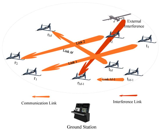
Figure 1.
Communication and interference of the directional UAV ad hoc network.
In this paper, the horizontal direction of data communication is considered to have a narrow beamwidth angle, while the elevation direction has a wide beamwidth angle. It is assumed that covering the nodes in the horizontal direction also achieves coverage in the elevation direction. Therefore, this paper only needs to consider the interference generated by directional coverage in the two-dimensional horizontal direction [3]. Although the topology of UAVs and communication links may change rapidly according to mission requirements, and multiple-hop paths and route forwarding exist in a large-scale scenario, a DUANET consists of specific point-to-point communication links over a period of time from the perspective of the MAC layer [16]. For the sake of generality in research, it is assumed that communication node pairs remain unchanged over a period of time [22,23,24]. It should be noted that in this paper, the meaning of beamwidth is the same as that of main lobe angle.
2.1.1. Directional Communication Model
We assume a directional network consisting of 2M UAVs forming M links in Figure 1. Considering sidelobes of directional antennas [42,43], the transmitter and receiver of the i-th link are and , respectively. The directional antenna gain of is expressed as
where and denote the main lobe pointing direction and communication direction, respectively, at time slot k for , and represents the main lobe angle of the directional antenna. is the directional antenna gain of at time slot k, measured in dB.
In Figure 1, ’s directional antenna gain model is expressed as
where and represent the main lobe pointing direction and the communication direction of the directional antenna, respectively, at during time slot k.
The interference gain from to is given as
where represents the main lobe direction of ’s directional antenna at time slot k, and represents the direction of the line connecting to at time slot k, as shown in Figure 2.

Figure 2.
Main lobe direction and direction of the line connecting to .
In the process of communication, each link’s transmitter and receiver achieve mutual main lobe coverage. During communication, the transmitter of each link will cause interference to the receiver of other links. The receiver ’s relative reception gain with respect to other transmitter is shown as follows:
where denotes the direction of the link from to at time slot k.
The external malicious interference node uses a fixed main lobe width for directional interference in different directions. The external horizontal interference over 360° can be achieved after scans. The relationship between and is given by Equation (5). The direction of the interference node’s main lobe periodically varies, denoted as .
The interference gain of the external interference node on the receiver of link i in the network is given as
where is a constant value, represents the direction of the main lobe centerline of the external interference node at time slot k, and represents the direction from the external interference node to the receiver of link i at time slot k. represents the main lobe angle of the directional antenna employed by the external interference node.
The interference reception gain of to the external interference node is given as
where represents the direction of the main lobe at the receiver of link i, and represents the direction from the receiver of link i to the external interference node.
According to Equations (1)–(4), (6) and (7), the Signal-to-Interference-plus-Noise Ratio (SINR) of the receiver of link i at time slot k is given as
where represents the channel state information (CSI) between the transmitter and receiver of link i at time slot k, represents the CSI from to at time slot k. and represent the transmission power of link i and link j at time slot k, respectively. is the set of all links, is the power spectral density of the additive white Gaussian noise, and is the communication bandwidth. indicates whether link i occupies time slot k. When is 0, it indicates that the time slot k is not occupied by link i, and the SINR is 0. When is 1, the corresponding SINR is obtained based on the power and direction gain according to (8). Therefore, when is 1, the power and main direction scheduling allows for control over both the SINR of the link itself and the SINR of neighboring links, thereby achieving control over the overall network transmission rate. Specifically, is defined as
According to the Jakes channel model [44], small-scale fading can be modeled as a first-order complex Gaussian–Markov process, represented as
where the noise follows a distribution, is . The correlation coefficient in Equation (10) is given by
where represents the zeroth-order Bessel function of the first kind, represents the maximum Doppler frequency, and represents the time interval of each time slot.
Furthermore, at time slot k, the amount of data that can be transmitted is given by
2.1.2. The Model for Data to Be Transmitted
Assuming there are K time slots in one frame, T = {1, 2, 3, …, K} represents the set of all time slots within one frame. The amount of data packets generated by each link at each time slot follows a Poisson distribution with Poisson arrival rate [45]. At time slot k, the probability distribution of the number of data packets generated by link i can be expressed as
where represents the number of data packets generated by link i at time slot k. After data packets are generated, they are placed into the packet buffer. The minimum number and the maximum number of the packets in the packet buffer are 0 and , respectively. The packets in the buffer are transmitted in a first-in-first-out (FIFO) manner. At time slot k, the remaining data packets for communication on link i are , which is given by [41]
where denotes the maximum number of data packets transmitted by link i at time slot k, and is represented as
When , data packets are transmitted by link i at time slot k. Here, denotes the minimum communication rate, represents the size of one data packet, and denotes the floor function.
2.2. Problem Formulation
In summary, by scheduling of the time slots, transmission power, and the main lobe directions for all UAVs, the goal is to maximize the total count of transmitted data packets. To achieve this, the optimization problem for MDRS is defined as
where represents the time slots occupancy for all links, and represents the power for all links in one frame, measured in dBm. represents the main lobe directions at the transmitter and receiver of all links. Maximizing represents maximizing the total count of data packets transmitted in one frame. represents the actual number of data packets transmitted on link i at time slot k [41]. As the number of packets in the packet buffer is less than the maximum transmission capacity , packets are transmitted by link i at time slot k. As is bigger than , packets are transmitted by link i at time slot k. In Equation (17), C1 represents the time slot occupancy constraints, C2 represents power constraints, and C3 and C4 represent the main lobe direction constraints for transmitters and receivers of all links. C5 is the constraint on the minimum number and the maximum number of data packets in the packet buffer. C6 represents the constraint on the minimum communication rate.
Up to time slot k, the total count of transmitted data packets for link i is , and the vector of for all links is . The long-term fairness across different links can be measured using the Jain fairness index [46]. Hence, combined with , the Jain fairness index is defined as
where represents fairness in the count of transmitted data packets for all links. approaching 1 indicates better fairness in the count of transmitted data packets for all links.
To maximize the count of transmitted data packets for all links and consider fairness, combining Equation (18), the optimization objective P1 from Equation (17) is further modified to P2 in (19). The objective can be viewed as maximizing the fairness-weighted count of transmitted data packets, which is given by
Problem P2 is difficult to solve primarily for three reasons: firstly, constraint C1 imposes an integer constraint. Secondly, in the process of maximizing through scheduling of the time slot, power, and main lobe direction, P2 involves a non-convex mixed-integer nonlinear programming problem for the communication rates . Lastly, due to the dynamic number of data packets in a packet buffer across time slots, solving P2 requires considering different states, making real-time algorithmic guarantees challenging. Methods like BCD, SCA, and other convex optimization algorithms [16,17,18,19,20] require a centralized deployment and subsequent policy distribution, leading to delayed decision-making and difficulty adapting to the dynamic number of packets in a packet buffer. Distributed reinforcement learning can enhance the real-time capability decision-making, alleviate computation pressure on individual systems, and adapt to the dynamic state of the system.
To this end, a MADRL algorithm is employed to solve problem (19), obtaining corresponding policies through training to adapt to the dynamic state of the system in this paper. In order to employ MADRL to solve MDRS, the first step is to formulate MDRS as a Dec-POMDP. The state, observation, action, and reward in the Dec-POMDP framework serve as components of the MADRL algorithm, which is used to make action decisions and, thereby, solve the optimization problem.
3. The Dec-POMDP for the MDRS Problem
For the Dec-POMDP, the environment information is described by state. The observation provides partial information about the state, and each agent receives an individual observation for the decentralized execution. Subsequently, each agent selects an action according to the received individual observation. The joint action of all agents results in a transition to the next state. Meanwhile, all agents receive a shared reward . The experience is composed of state, observation, action, and reward, represented by tuple . The experiences are stored in the experience replay buffer for centralized training.
In solving the problem defined in Equation (19), algorithm deployments must be considered. The time slot occupancy and power control are controlled at the transmitter, while the main lobe direction control pertains to both the transmitter and receiver. Therefore, in this paper, each link is regarded as an agent, with the network trained using MADRL deployed at the transmitter of each link for decision-making.
In the MADRL with centralized training and decentralized execution (CTDE), the centralized training is conducted at the ground station depicted in Figure 1. The ground station distributes the trained neural networks to the transmitters of each link for decentralized execution.
3.1. Action of the Dec-POMDP
According to Equation (19), the four-dimensional action space is described as
where , , and represent the power action space, transmitter main lobe direction action space, and receiver main lobe direction action space, respectively. Therefore, , , and are as shown as
where a 0 in and indicates that the main lobe direction is the same as the communication direction. The action space for is the Cartesian product of the action spaces for , , , and ; thus, the size of the action space size is . To further reduce the action space, when link i does not occupy time slot k, both the power and main lobe directions of link i are set to 0. Therefore, the size of the action space is .
The transmitter interferes with the receivers of other links within its main lobe range with the same power. Therefore, each link’s transmitter makes main lobe direction decisions by maximizing the following equation:
where represents the set of receivers of other links within the main lobe range of transmitter i. Therefore, the size of the reinforcement learning action space is reduced to .
3.2. State of the Dec-POMDP
In MADRL based on QMIX [47], global state information is used for centralized training, while during execution, each agent has only observation information. At time slot k, the global state is represented as
where represents the set of channel state information at time slot k. and have the same meaning. and are the same meaning. Based on channel symmetry, and are the same. denotes the set of directional gain among all transmitters and receivers at time slot k. indicates the remaining data packet in packet buffer at each time slot. represents the interference power of external interference on receivers of all links.
3.3. Observation of the Dec-POMDP
An agent can only observe a portion of the global state to decide its action. In practical scenarios, at the transmitter and receiver of link i, only the state information of links within its main lobe and links that cover the transmitter and receiver of link i by the main lobe can be observed. The observations by the transmitter and receiver of link i at time slot k are represented as
where represents the channel state information from the receiver and transmitter of link i to all links whose transmitters and receivers are within the main lobe of link i, as well as to other links whose transmitters and receivers can cover link i’s receiver and transmitter within the main lobe range. is the set of the links that can be observed by link i at time slot k. represents the directional gain from the receiver and transmitter of link i to transmitters and receivers of all links within the main lobe range of link i, as well as to other links whose transmitters and receivers can cover the receiver and transmitter of link i within the main lobe range. and have the same meaning as and , respectively. and indicate the count of transmitted packets and the number of packets in a packet buffer for the link itself and links within the observed range, respectively. denotes the received interference power from the external interference node to receivers of link i and link i’s neighbors. At time slot k, the observations of all links are combined as
3.4. Reward of the Dec-POMDP
For the DUANET, all links strive for a common global goal. The global reward function, which describes the communication performance of all links, is shown as
where is the number of data packets actually transmitted by link i at time slot k, which is shown as
4. Attention Mechanism and MADRL Algorithm
This section primarily introduces the observation processing methods for variable dimension observations and MADRL algorithms. Due to varying numbers of neighboring UAVs observed within different main lobe ranges, the dimensions of the observation to be processed differ. It is necessary to map observed features into vectors of equal length while ensuring essential information is preserved during the dimensional transformation of observation data. To address this, a multi-head attention mechanism to solve this issue is proposed in this paper, ensuring inputs for the MADRL algorithm’s training and execution.
The main goal of this paper is to maximize rewards across the network through collaborative interactions among agents, necessitating the use of fully cooperative reinforcement learning algorithms. Building on the Dec-POMDP framework introduced in the previous section, this section combines the Value-Decomposition Network (VDN) [48], QMIX [47], and the newly proposed QMIX algorithm with the multi-head attention mechanism (QMIX-Attn) to form the DMDRS based on VDN (DMDRS-VDN), DMDRS based on QMIX (DMDRS-QMIX), and DMDRS-QMIX-Attn algorithms to slove the MDRS problem. In this section, we first propose the attention mechanism for observation processing and then introduce VDN, QMIX, and QMIX-Attn.
4.1. Observation Processing Based on Attention Mechanism
Most MADRL algorithms employ MLP [32,33,49,50] to process observation data. However, MLP can only handle fixed-dimensional observations and is not suitable for varying-dimensional observations data within the main lobe range as described in (24). In practice, observation data exhibit certain patterns that can be utilized to extract features and construct equally sized observation vectors. Therefore, a method based on graph attention mechanisms [51] is proposed to extract dynamic dimensional observation features in this paper. In the observation of link i, the initial features of links to self-link and neighboring links are represented by expressions and in the following equation, respectively.
where ∖ represents the set difference operation in mathematics, is the concatenation function, and represents the received interference power from the external interference node to receivers of link i. Based on observed initial features, the weighting coefficient for link i observing link j in time k is given by
where LeakyRelu represents Leaky Relu function [52]. Parameters , , are weights to be trained. Thus, the abstracted features derived from the observations are the weighted sum of the features obtained from other neighboring links for the current link i, which is shown as
where represents non-linear activation function.
To further enhance training stability, the process can be independently repeated as described above, and multiple output results can be combined to form a multi-head attention mechanism [51]. At time slot k, the features of other links obtained by agent i’s observation range are given by
4.2. QMIX Algorithm and QMIX-Attn Algorithm
The VDN algorithm [48] links the global Q-value with local Q-values through value decomposition, overcoming the instability of IQL [53]. The joint action-value function of VDN is . represents the Q-value function of agent i. represents the network policy parameters of agent i. In VDN, maximizing the system’s is equivalent to maximizing each agent’s . Therefore, we can obtain their decentralized policies by maximizing each agent’s individually.
VDN approximates the global Q-value by summing local Q-values , but the addition cannot represent the complexity of and . If the relationship between and is complex, the trained policy may deviate from the optimization goal. Therefore, the QMIX [47] method is proposed to approximate using a neural network, better fitting the relationship between and . It should be noted that when each ’s weight is approximately equal, VDN may slightly outperform QMIX.
Since VDN ignores the global state information available during the training phase, QMIX uses the global state in addition to approximating . To better approximate , QMIX ensures that and each agent’s have the same monotonicity by restricting the parameters in the neural network to be non-negative, thus satisfying (32).
By ensuring that and have the same monotonicity, the argmax operation on is equivalent to the argmax operation on each . The relationship of ’s monotonicity and ’s monotonicity can be expressed as
Combining the multi-head attention mechanism in Section 4.1, the architecture of the QMIX-Attn algorithm is shown in Figure 3. Compared to the QMIX algorithm, the QMIX-Attn algorithm replaces the fully-connected (FC) layer in the Q-network input layer of QMIX with an attention mechanism layer. In Figure 3a, the local Q-network represents for each agent. It computes Q-values for all actions in the action space based on the agent’s observation features processed by the multi-head attention mechanism. Based on these Q-values, the optimal action is determined by using an arbitrary policy.
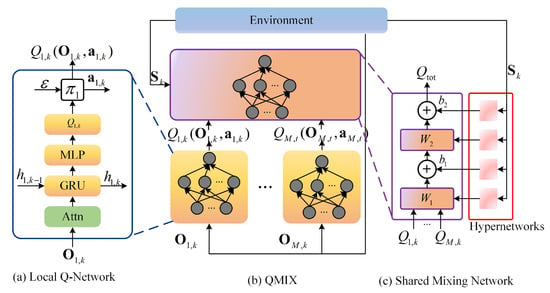
Figure 3.
The architecture of the QMIX algorithm based on the multi-head attention mechanism.
Figure 3c depicts the hypernetworks and the mixing network. Each hypernetwork takes global state information as input and generates the weights of a layer of the mixing network. To ensure the non-negativity of the weights, a linear network with an absolute value activation function is used to ensure that the output is not negative. The bias is treated similarly but without the non-negativity constraint. The bias of the last layer of the mixing network is obtained through a two-layer network with a ReLU activation function for nonlinear mapping.
This paper adopts the CTDE framework. The agent selects an action based on an -greedy policy and interacts with the environment. The training process is divided into epochs, and each epoch consists of episodes, and each episode has steps. At the beginning of each episode, to ensure the generalization capability of the training results, the state space is initialized with an initial state. During time slot k, the tuple representing the interaction between the agent and the environment is stored in the experience replay buffer . Experiences are sampled from and utilized for parameter optimization using stochastic gradient descent (SGD). The DQN approach is adopted for algorithm update, and the cost function is given by
where represents the batch of episodes sampled from the experience replay buffer, and is defined as
Algorithm 1 presents the QMIX-Attn algorithm process. Compared to the QMIX algorithm, the attention mechanism for observation processing is added.
| Algorithm 1 Training process of QMIX-Attn |
|
4.3. Complexity Analysis for QMIX-Attn
Since the training is offline, we focus on the computational complexity during the online execution phase. The computational complexity for each agent during the execution phase primarily depends on the forward computation of the well-trained Q-network. The Q network of each agent consists of an input layer with an attention mechanism module, an output layer with FC layers, and a gated recurrent unit (GRU). The computational complexity of the multi-head attention mechanism is [54], where represents the number of attention heads, and and represent the input and output dimensions of the multi-head attention mechanism, respectively. represents the number of observed neighboring links. The main operations of the FC layer include multiplying the input vector by a weight matrix and adding a bias term. Its computational complexity is [55], where and represent the input and output dimensions of the FC layer, respectively. The computation in the GRU layer requires two matrix multiplications and a series of element-wise operations, including the reset gate, update gate, and hidden state gate. The computational complexity is [56], where and represent the input dimension and hidden state dimension of the GRU layer, respectively. Therefore, the computational complexity of the Q-network is , where and represent the input dimension of the observations and the dimension of observation features based on the multi-head attention mechanism, respectively. denotes the size of the action space.
The main difference between QMIX and QMIX-Attn lies in the input layer of the Q network. The input layer of QMIX is an FC layer, so the computational complexity of the input layer is . and represent the dimensions of the input and output of the input FC layer, respectively. Therefore, the computational complexity of QMIX is . Compared to the QMIX algorithm, the computational complexity of QMIX-Attn is slightly higher.
5. Simulation and Analysis
In this paper, the effectiveness and advancement of the QMIX-Attn algorithm are verified through a comparison of the DMDRS-VDN, DMDRS-QMIX, and DMDRS-QMIX-Attn algorithms. The algorithms were simulated to analyze and validate their performance in scenarios with different parameters. To compare the effectiveness of the main lobe direction scheduling, the main lobe directions of the transmitters and receivers of all links were both 0, with only the time slot and power scheduling, to verify that scheduling the main lobe direction can further improve the fairness-weighted count of transmitted data packets. Consequently, DMDRS-VDN, DMDRS-QMIX, and DMDRS-QMIX-Attn are simplified to DMDRS based on VDN without the main lobe direction scheduling (DMDRS-VDN-ND), DMDRS based on QMIX without the main lobe direction scheduling (DMDRS-QMIX-ND), and DMDRS based on QMIX-Attn without the main lobe direction scheduling (DMDRS-QMIX-Attn-ND), respectively.
5.1. Simulation Scenarios and Algorithm Parameters
5.1.1. Simulation Scenarios
In a DUNET, assume there are 10 links ready to perform data transmission. The 20 UAVs for these 10 links are deployed in a 10 km by 10 km area, forming a fixed topology. Each UAV randomly moves to any position within a circle of radius (0, 40 m, 80 m, 120 m, 160 m, 200 m) centered at its deployment location for broader reconnaissance.
Using the Jakes model to simulate dynamic small-scale fading channels [44], the Doppler frequency was set to 1000 Hz. Large-scale fading was simulated using the path loss formula [57], with the carrier frequency set to 5 GHz. The power spectral density of additive white Gaussian noise (AWGN) was −174 dBm/Hz. The maximum transmission power was 38 dBm, and the minimum transmission power was 5 dBm. The number of power levels D was 9. Both and were 5.
Unless otherwise specified, the main lobe angle of the directional antenna was 20°, the main lobe gain of the directional antenna was 15 dB, and the side lobe gain of the directional antennas was 0 dB. Each data packet size was set to 50 kbits. The maximum number of packet in a packet buffer was 50, the data packet generation rate was 12 packets per time slot, and the minimum communication rate was 22.5 Mbps. The parameter settings are shown in Table 2.

Table 2.
Parameters for the simulation scenarios.
5.1.2. Algorithm Parameters
In this study, each training episode (frame) consisted of 20 steps (time slots), with 20 episodes per epoch. Each algorithm included 10 policy networks for agents, structured as DRQN with a convolutional layer and 256 GRUs. The QMIX algorithm and QMIX-Attn additionally featured a mixer network and hypernetwork. The mixer network comprised a hidden layer with 64 neurons using the ELU activation function. The hypernetwork, responsible for non-negative network weights training for the mixer network, included a hidden layer with 64 neurons and utilized the ReLU activation function.
During the training phase, each agent employd a -greedy policy for exploring the action space. The exploration rate decayed from 0.4 to 0.05 over 10,000 steps, after which it remained constant at 0.05. The discount factor for reinforcement learning was set to 0.98. Network parameters were updated using the RMSprop optimizer [58] with a learning rate of 0.0005. Each time, we sampled a batch of 32 episodes from the experience replay buffer. The target networks were updated every 40 steps. In the observation processing based on multi-head attention mechanisms, the number of heads was 4.
The algorithm parameters are as shown in Table 3. The number of steps in an episode is also the number of slots in a frame.

Table 3.
Parameters for algorithms.
The environment and algorithms for simulation were implemented in Python 3.10.9 and PyTorch 1.12.1.
5.2. Comparison of Different Algorithms
In this section, we mainly compare DMDRS-VDN, DMDRS-QMIX, DMDRS-QMIX-Attn, DMDRS-VDN-ND, DMDRS-QMIX-ND, and DMDRS-QMIX-Attn-ND to validate the performance of different algorithms.
The main optimization goal of this paper is to maximize the fairness-weighted total count of transmitted data packets by scheduling the time slot, power, and main lobe direction. Hence, this section primarily compares the performance of the proposed algorithm and baselines in terms of the fairness-weighted count of transmitted data packets, the fairness index, and the total count of transmitted data packets [39,40]. The calculation method for the fairness-weighted count of transmitted data packets and the total count of transmitted data packets are obtained through the optimization objectives in Equations (17) and (19), respectively. The calculation method for the fairness index is obtained in Equation (18), in which k is 20.
Figure 4 shows the convergence curves of different algorithms in terms of the fairness-weighted count of transmitted data packets, which shows that the QMIX-Attn algorithm obtained the best performance. For processing observations, the self-attention mechanism has an advantage over the MLP encoder due to its use of smaller parameter vectors for training and execution. Essentially, the permutation invariance of QMIX-Attn reduces the dimension of the observation-action space, thus enhancing the algorithm’s performance. Compared to DMDRS-VDN, DMDRS-QMIX performs better due to the stronger fitting characteristics of its mixing network.
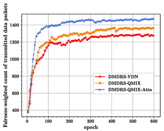
Figure 4.
The convergence curves of different algorithms with the main lobe direction scheduling.
In terms of training efficiency, the proposed QMIX-Attn outperforms the QMIX and VDN algorithms. This is mainly because the attention mechanism extracts more effective features, enabling the algorithm to converge quickly.
Figure 5 shows the convergence curves for different algorithms without the main lobe direction scheduling in terms of the fairness-weighted count of transmitted data packets, where the QMIX-Attn algorithm still performs the best. Comparing Figure 4 and Figure 5, the fairness-weighted count of transmitted data packets with the main lobe direction scheduling is better than that without the main lobe direction scheduling. The main reason is that the main lobe direction scheduling reduces external and internal interference, thus enhancing network transmission performance.
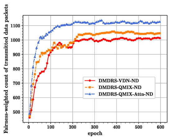
Figure 5.
The convergence curves of different algorithms without the main lobe direction scheduling.
Based on the networks trained with the algorithms from Figure 4 and Figure 5, Figure 6, Figure 7 and Figure 8 show the fairness-weighted count of transmitted data packets, the fairness index, and the total count of transmitted data packets per frame for different algorithms, respectively. In Figure 6, the DMDRS-QMIX-Attn demonstrates the best performance in terms of the fairness-weighted count of transmitted data packets, resulting in better fairness and transmission performance compared to DMDRS-QMIX and DMDRS-VDN. Compared with the algorithms without the main lobe direction scheduling, the algorithms with the main lobe direction scheduling can enhance the DUANET’s fairness and packet transmission performance. The primary reason is that an algorithm with the main lobe direction scheduling can reduce interference from neighboring UAVs and the external interference node, thereby improving the network’s transmission performance.
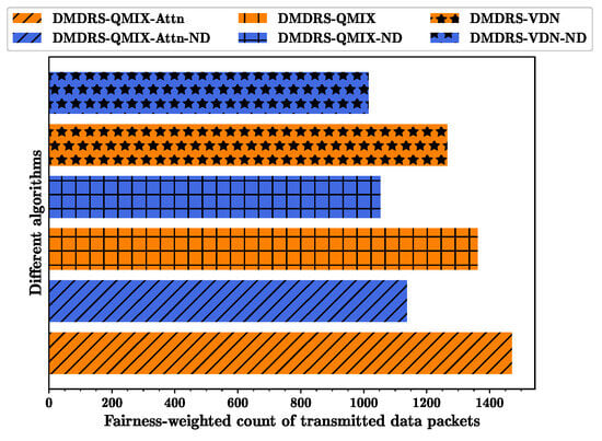
Figure 6.
Fairness-weighted count of transmitted data packets for different algorithms.
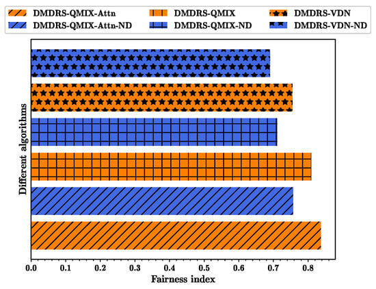
Figure 7.
Fairness index for different algorithms.
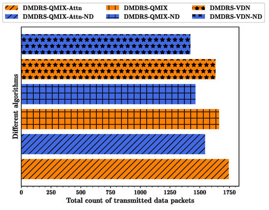
Figure 8.
Total count of transmitted data packets for different algorithms.
5.3. Comparison of Scenarios with Different Parameters
In this section, we mainly verify the superiority of the proposed algorithm under different scenarios. Hence, we conducted a simulation and analysis on scenarios with different data packet generation rates, different main lobe gains, and different main lobe widths. The following simulation results are based on the execution after 600 epochs of training. In order to verify the adaptability and scalability of the proposed algorithm in dynamic environments, the channel environment is randomly generated according to the set parameters, and the number of packets to be transmitted for each link is randomly generated based on a Poisson distribution.
From Figure 4, Figure 5, Figure 6, Figure 7 and Figure 8, DMDRS-QMIX-Attn and DMDRS-QMIX outperform DMDRS-VDN to solve the MDRS problem. For DMDRS algorithms without main direction scheduling, DMDRS-QMIX-Attn-ND outperforms DMDRS-QMIX-ND and DMDRS-VDN-ND. Therefore, we further compare the three algorithms: DMDRS-QMIX-Attn, DMDRS-QMIX, and DMDRS-QMIX-Attn-ND. The comparison between DMDRS-QMIX-Attn and DMDRS-QMIX validates the effectiveness of the proposed attention mechanism, while the comparison between DMDRS-QMIX-Attn and DMDRS-QMIX-Attn-ND validates the advantages of the main lobe direction scheduling.
5.3.1. The Performance with Different Data Packet Generation Rates
First, the impact of different Poisson distribution parameters on the proposed algorithm is considered. The essence of the different Poisson distribution parameters is the different data packet generation rates.
Figure 9, Figure 10 and Figure 11 show the performance of three different metrics under scenarios with different data packet generation rates for various algorithms. As the data packet generation rate increases, the fairness-weighted count of transmitted data packets does not always increase. The main reason is that as the data packet generation rate increases, the fairness index tends to decrease while the total count of transmitted data packets increases. The fairness index and the total count of transmitted data packets jointly affect the fairness-weighted count of transmitted data packets.
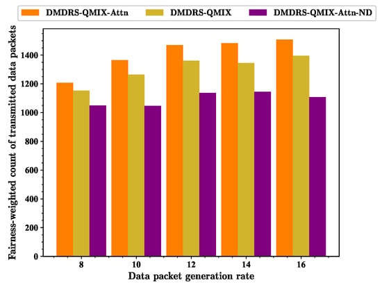
Figure 9.
Fairness-weighted count of transmitted data packets for scenarios with different data packet generation rates.
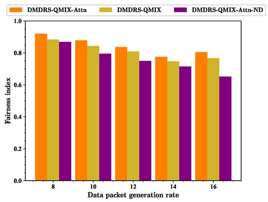
Figure 10.
Fairness index for scenarios with different data packet generation rates.
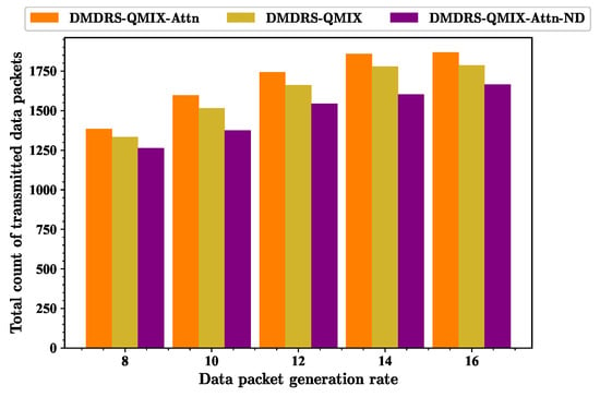
Figure 11.
Total count of transmitted data packets for scenarios with different data packet generation rates.
As the data packet generation rate increases, the fairness index gradually decreases. The fundamental reason for this is that as each link generates more data packets, the algorithm tends to allow links with better interference scenarios to transmit data for the better fairness-weighted count of transmitted data packets, leading to a decline in transmission fairness.
As the data packet generation rate increases, the total count of transmitted data packets of all algorithms shows an upward trend. The proposed attention mechanism for observation processing and the main lobe direction scheduling improves the fairness index and the total count of transmitted data packets with different data packet generation rates.
5.3.2. The Performance with Different Main Lobe Gains
Next, we conducted a simulation and analysis of different algorithms under varying main lobe gains. The performance of three different metrics for different main lobe gains are shown in Figure 12, Figure 13, and Figure 14, respectively. As the main lobe gain increases, three metrics for different algorithms exhibit an upward trend.
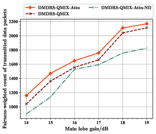
Figure 12.
Fairness-weighted count of transmitted data packets for scenarios with different main lobe gains.
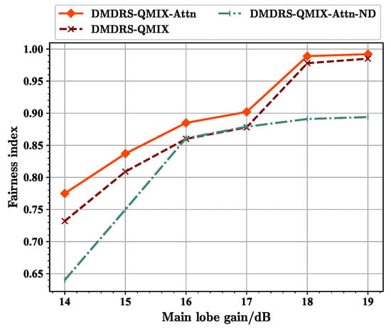
Figure 13.
Fairness index for scenarios with different main lobe gains.
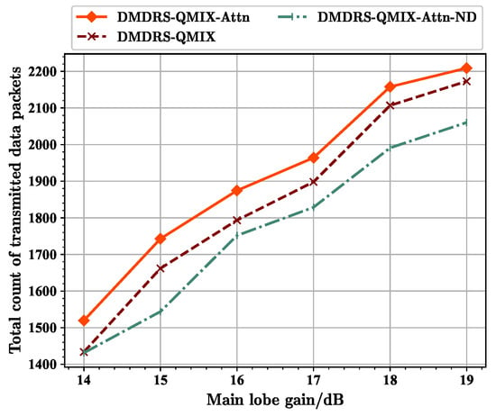
Figure 14.
Total count of transmitted data packets for scenarios with different main lobe gains.
From Figure 12, it can be seen that at 16 dB, the fairness-weighted count of transmitted data packet of the DMDRS-QMIX-Attn-ND algorithm approaches that of the DMDRS-QMIX algorithm. This is related to different main lobe gains. Under the scenario with a gain of 16 dB, the benefit of algorithm with the main lobe direction scheduling is small, resulting in the DMDRS-QMIX-Attn-ND using only the attention mechanism and achieving a performance close to the DMDRS-QMIX algorithm. From Figure 13, it can be seen that at main lobe gains of 16 dB and 17 dB, the fairness index of the DMDRS-QMIX-Attn-ND algorithm is even slightly better than that of the DMDRS-QMIX algorithm. However, from Figure 14, it can be seen that the DMDRS-QMIX algorithm obtained a better performance in terms of the total count of transmitted data packets compared with the DMDRS-QMIX-Attn-ND algorithm. The strategy learned by the DMDRS-QMIX algorithm is to achieve a better performance by increasing the total count of transmitted data packets.
Overall, due to the attention mechanism and main lobe direction scheduling, the DMDRS-QMIX-Attn algorithm obtained a better performance under scenarios with different main lobe gains.
5.3.3. The Performance with Different Main Lobe Widths
Finally, the impact of main lobe beamwidth on network and algorithm performance was examined by varying the main lobe width. Additionally, changing the main lobe beamwidth will alter the number of UAVs observed within the main lobe range. Here, the maximum gain of directional communication remains unchanged, which is 15dB. By varying the main lobe width, the proposed algorithm’s superiority under dynamic numbers of neighboring nodes is further validated.
For the fairness-weighted count of transmitted data packets, it can be seen that the proposed DMDRS-QMIX-Attn performs the best in Figure 15. When the beamwidth is 10°, the fairness-weighted count of transmitted data packets is optimal due to the reduced mutual interference between each link in the DUANET. Additionally, because the observation range is smaller and the number of observed nodes is lower, the performance advantage of the self-attention mechanism in feature extraction is only improved by 3.57%. Thus, the performance improvement in terms of the fairness-weighted count of transmitted data packets of DMDRS-QMIX-Attn based on the attention mechanism is not significant compared to DMDRS-QMIX based on MLP. When the beamwidth is 30°, the mutual interference and external interference among the links in the network increase, leading to a decrease in communication performance. However, since the number of observed nodes increases, the performance advantage of the self-attention mechanism in feature extraction becomes more significant, improving by 22.17%. Therefore, the DMDRS-QMIX-Attn algorithm, based on the attention mechanism, can achieve better performance in terms of the fairness-weighted count of transmitted data packets compared with the DMDRS-QMIX based on MLP.
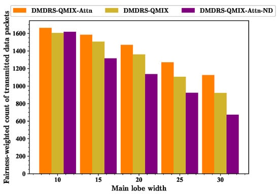
Figure 15.
Fairness-weighted count of transmitted data packets for scenarios with different main lobe widths.
From Figure 6, Figure 7 and Figure 8, it can be seen that the the main lobe direction scheduling can mitigate mutual interference between networks. Combined with Figure 15, it can be further concluded that the main lobe direction scheduling cannot completely avoid internal and external interference in the communication system but can only reduce internal network interference. This is also the reason why narrowing the main lobe width reduces mutual interference between links and external interference, thereby further improving the fairness-weighted count of transmitted data packets of the entire network.
When the main lobe width increases and the mutual interference between links grows, the main lobe direction scheduling for improving the fairness-weighted count of transmitted data packets becomes more significant. At this time, the adjustable range of the main lobe also expands. When the beamwidth is 10°, the DMDRS-QMIX-Attn algorithm only improves the fairness-weighted count of transmitted data packets by 2.78% compared to the DMDRS-QMIX-Attn-ND algorithm. However, when the beamwidth is 30°, the fairness-weighted count of transmitted data packets of DMDRS-QMIX-Attn and DMDRS-QMIX-Attn-ND are 1125.89 and 673.94, respectively. Therefore, we can conclude that the DMDRS-QMIX-Attn algorithm improves the fairness-weighted count of transmitted data packets by 67.06% compared to the DMDRS-QMIX-Attn-ND algorithm under this beamwidth scenario.
Figure 16 shows the fairness index of different algorithms. The DMDRS-QMIX-Attn algorithm is not always optimal in terms of the fairness index. This is mainly because the optimization goal is to maximize the fairness-weighted count of transmitted data packets rather than the fairness index. As shown in Figure 17, DMDRS-QMIX-Attn has the best performance in terms of the total count of transmitted data packets. Therefore, it can be concluded that a better fairness index does not necessarily improve the performance in terms of the fairness-weighted count of transmitted data packets. Combining Figure 9 and Figure 10, it is further demonstrated that the fairness-weighted count of transmitted data packets is jointly determined by the fairness index and the total count of transmitted data packets.
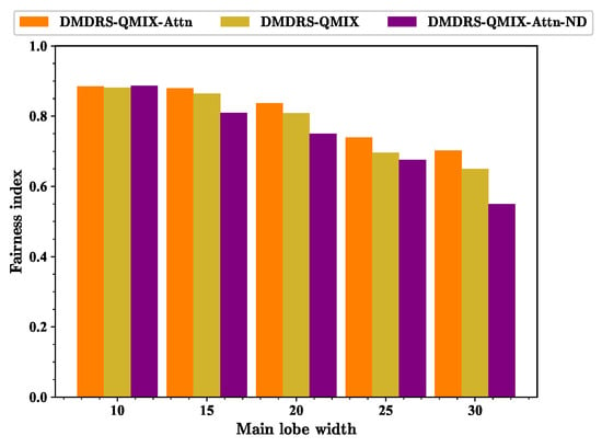
Figure 16.
Fairness index for scenarios with different main lobe widths.
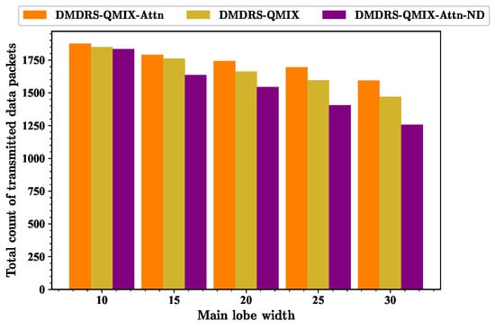
Figure 17.
Total count of transmitted data packets for scenarios with different main lobe widths.
Figure 17 shows the total count of transmitted data packets of different algorithms. As the beamwidth is 30°, the fairness index of DMDRS-QMIX-Attn and DMDRS-QMIX is 0.702 and 0.65, respectively. The performance of DMDRS-QMIX-Attn and DMDRS-QMIX is 1594.2 and 1469.9 in terms of the total count of transmitted data packets, respectively. Therefore, the attention mechanism achieves better performance than MLP. The performance of DMDRS-QMIX-Attn-ND is 0.55 and 1256.9 in terms of the fairness index and the total count of transmitted data packets, respectively. Hence, compared with DMDRS-QMIX-Attn, we can conclude that the scheduling of the time slot, power, and main lobe direction achieves better communication performance than the scheduling of only the time slot and power. For the scenarios with different main lobe widths, DMDRS-QMIX-Attn achieves the best performance of the total count of transmitted data packets. Its performance improvement mainly stems from the algorithm’s attention mechanism and main lobe direction scheduling.
6. Discussion
The proposed algorithm can be applied to various DUANET scenarios, such as collaborative military reconnaissance, earthquake rescue, and communication support in civilian applications. For future applications, we plan to deploy the training phase of the algorithm at a ground station and then deploy the Q-network trained by the ground station at the transmitters to enable autonomous resource scheduling decisions by UAVs. Since MADRL algorithms generally assume clock synchronization, ensuring the synchronization of clocks across all network nodes is crucial in practical applications. However, achieving strict clock synchronization in an engineering application is challenging. Therefore, how to perform resource scheduling with clock errors is a key issue that needs to be addressed for the proposed algorithm in practical engineering. This is a system design issue that involves the coupling of the physical layer, the Media Access Control (MAC) layer, and the proposed algorithm. We plan to adopt a more precise network synchronization algorithm and a MAC layer protocol designed for information exchange to ensure resource scheduling even in the presence of errors.
Next, we will consider using directional antenna models in practical engineering to achieve multi-dimensional resource scheduling for time, frequency, spatial, and power domains. The scheduling of the main lobe direction is related to the granularity of the actual directional antenna, so the action space for the main lobe direction needs to be adjusted according to the actual granularity [3]. Another challenge lies in the fact that reinforcement learning optimization for more dimensions of resources will lead to an excessively large action space, resulting in less effective multi-dimensional resource scheduling. Therefore, addressing the issue of large action spaces in reinforcement learning will be a key challenge for future work.
7. Conclusions
This paper proposes a MADRL algorithm to enhance network transmission performance by joint scheduling of the time slot, power, and main lobe direction in DUANETs. First, The MDRS problem is formulated to maximize the fairness-weighted count of transmitted data packets, which can be reformulated as the Dec-POMDP. Then, an attention mechanism is proposed to handle the dynamic dimensional observations of Dec-POMDP, and a QMIX-Attn algorithm is introduced by combining this attention mechanism with the QMIX algorithm. Finally, VDN, QMIX, and QMIX-Attn are used to solve the constructed Dec-POMDP. Simulation comparisons in various scenarios show that the proposed QMIX-Attn algorithm outperforms both QMIX and VDN algorithms in terms of the fairness-weighted count of transmitted data packets. Compared with algorithms without the main lobe direction scheduling, the proposed algorithm achieves better transmission fairness and total count of transmitted data packets. As the main lobe width increases, the performance of the attention mechanism and main lobe direction scheduling improves further. With a main lobe width of 30°, the attention mechanism and main lobe direction scheduling improve the optimization objectives by 22.17% and 67.06%, respectively.
In the discussion, we address the practical applications, limitations, and challenges of the proposed algorithms. We also provide an outlook on our future work.
Author Contributions
This research was accomplished by all the authors: S.L., H.Z., L.Z., J.W., Z.W. and K.C. conceived the idea, performed the analysis, and designed the scheme; S.L., H.Z. and L.Z. conducted the numerical simulations; S.L., J.W., Z.W. and K.C. co-wrote the manuscript. All authors have read and agreed to the published version of the manuscript.
Funding
This research was funded in part by the National Natural Science Foundation of China, grant No. 62171449, No. 62201584, and No. 62106242, and the National Natural Science Foundation of Hunan Province, China, grant No. 2021JJ40690.
Data Availability Statement
Data are contained within the article.
Conflicts of Interest
Shijie Liang and Junfang Wang are employed by the 54th Research Institute of China Electronics Technology Group Corporation. The remaining authors declare that the research was conducted in the absence of any commercial or financial relationships that could be construed as a potential conflict of interest.
References
- Wang, H.; Zhao, H.; Zhang, J.; Ma, D.; Li, J.; Wei, J. Survey on unmanned aerial vehicle networks: A cyber physical system perspective. IEEE Commun. Surv. Tutor. 2019, 22, 1027–1070. [Google Scholar] [CrossRef]
- Yun, W.J.; Park, S.; Kim, J.; Shin, M.; Jung, S.; Mohaisen, D.A.; Kim, J.H. Cooperative multiagent deep reinforcement learning for reliable surveillance via autonomous multi-UAV control. IEEE Trans. Ind. Inform. 2022, 18, 7086–7096. [Google Scholar] [CrossRef]
- Liang, S.; Zhao, H.; Zhang, J.; Wang, H.; Wei, J.; Wang, J. A Multichannel MAC Protocol without Coordination or Prior Information for Directional Flying Ad hoc Networks. Drones 2023, 7, 691. [Google Scholar] [CrossRef]
- Jan, S.U.; Abbasi, I.A.; Algarni, F. A key agreement scheme for IoD deployment civilian drone. IEEE Access 2019, 9, 149311–149321. [Google Scholar] [CrossRef]
- Arafat, M.Y.; Poudel, S.; Moh, S. Medium access control protocols for flying ad hoc networks: A review. IEEE Sens. J. 2020, 21, 4097–4121. [Google Scholar] [CrossRef]
- Wang, H.; Zhao, H.; Wu, W.; Xiong, J.; Ma, D.; Wei, J. Deployment algorithms of flying base stations: 5G and beyond with UAVs. IEEE Internet Things J. 2019, 6, 10009–10027. [Google Scholar] [CrossRef]
- Coyle, A. Using directional antenna in UAVs to enhance tactical communications. In Proceedings of the IEEE Military Communications and Information Systems Conference (MilCIS), Canberra, ACT, Australia, 13–15 November 2018. [Google Scholar]
- Li, P.; Zhang, C.; Fang, Y. The capacity of wireless ad hoc networks using directional antennas. IEEE Trans. Mob. Comput. 2010, 10, 1374–1387. [Google Scholar] [CrossRef]
- Liu, M.; Wan, Y.; Li, S.; Lewis, F.L.; Fu, S. Learning and uncertainty-exploited directional antenna control for robust long-distance and broad-band aerial communication. IEEE Trans. Veh. Technol. 2019, 69, 593–606. [Google Scholar] [CrossRef]
- Asahi, D.; Sato, G.; Suzuki, T.; Shibata, Y. Long distance wireless disaster information network by automatic directional antenna control method. In Proceedings of the IEEE 13th International Conference on Network-Based Information Systems, Takayama, Japan, 14–16 September 2010. [Google Scholar]
- Xue, Q.; Zhou, P.; Fang, X.; Xiao, M. Performance analysis of interference and eavesdropping immunity in narrow beam mmWave networks. IEEE Access 2018, 6, 67611–67624. [Google Scholar] [CrossRef]
- Zhu, L.; Zhang, J.; Xiao, Z.; Cao, X.; Xia, X.G.; Schober, R. Millimeter-wave full-duplex uav relay: Joint positioning, beamforming, and power control. IEEE J. Sel. Areas Commun. 2020, 38, 2057–2073. [Google Scholar] [CrossRef]
- Xiao, Z.; Zhu, L.; Xia, X.G. UAV communications with millimeter-wave beam forming: Potentials, scenarios, and challenges. China Commun. 2020, 17, 147–166. [Google Scholar] [CrossRef]
- Sha, Z.; Chen, S.; Wang, Z. Near interference-free space-time user scheduling for mmWave cellular network. IEEE Trans. Wirel. Commun. 2022, 21, 6372–6386. [Google Scholar] [CrossRef]
- Shin, K.S.; Jo, O. Joint scheduling and power allocation using non-orthogonal multiple access in directional beam-based WLAN systems. IEEE Trans. Wirel. Commun. 2017, 6, 482–485. [Google Scholar] [CrossRef]
- Wang, H.; Jiang, B.; Zhao, H.; Zhang, J.; Zhou, L.; Ma, D.; Leung, V.C. Joint resource allocation on slot, space and power towards concurrent transmissions in UAV ad hoc networks. IEEE Trans. Wirel. Commun. 2022, 21, 8698–8712. [Google Scholar] [CrossRef]
- Zhang, Z.; Wang, C.; Yu, H.; Wang, M.; Sun, S. Power optimization assisted interference management for D2D communications in mmWave networks. IEEE Access 2018, 6, 50674–50682. [Google Scholar] [CrossRef]
- Samir, M.; Sharafeddine, S.; Assi, C.M.; Nguyen, T.M.; Ghrayeb, A. UAV trajectory planning for data collection from time-constrained IoT devices. IEEE Trans. Wirel. Commun. 2019, 19, 34–46. [Google Scholar] [CrossRef]
- Wu, Q.; Zeng, Y.; Zhang, R.; Ghrayeb, A. Joint trajectory and communication design for multi-UAV enabled wireless networks. IEEE Trans. Wirel. Commun. 2018, 17, 2109–2121. [Google Scholar] [CrossRef]
- Wu, Y.; Yang, W.; Guan, X.; Wu, Q. UAV-enabled relay communication under malicious jamming: Joint trajectory and transmit power optimization. IEEE Trans. Veh. Technol. 2021, 70, 8275–8279. [Google Scholar] [CrossRef]
- Yuan, Y.; Li, Z.; Liu, Z.; Yang, Y.; Guan, X. Double deep Q-network based distributed resource matching algorithm for D2D communication. IEEE Trans. Veh. Technol. 2021, 71, 984–993. [Google Scholar] [CrossRef]
- Qu, N.; Wang, C.; Li, Z.; Liu, F.; Ji, Y. A distributed multi-agent deep reinforcement learning-aided transmission design for dynamic vehicular communication networks. IEEE Trans. Veh. Technol. 2024, 73, 3850–3862. [Google Scholar] [CrossRef]
- Li, X.; Lu, L.; Ni, W.; Jamalipour, A.; Zhang, D.; Du, H. Federated multi-agent deep reinforcement learning for resource allocation of vehicle-to-vehicle communications. IEEE Trans. Veh. Technol. 2022, 71, 8810–8824. [Google Scholar] [CrossRef]
- Zhou, Y.; Yu, F.R.; Ren, M.; Chen, J. Adaptive data transmission and computing for vehicles in the internet-of-intelligence. IEEE Trans. Veh. Technol. 2024, 73, 2533–2548. [Google Scholar] [CrossRef]
- Lu, T.; Zhang, H.; Long, K. Joint beamforming and power control for MIMO-NOMA with deep reinforcement learning. In Proceedings of the IEEE International Conference on Communications, Montreal, QC, Canada, 14–23 June 2021. [Google Scholar]
- Liu, M.; Wang, R.; Xing, Z.; Soto, I. Deep reinforcement learning based dynamic power and beamforming design for time-varying wireless downlink interference channel. In Proceedings of the IEEE Wireless Communications and Networking Conference (WCNC), Austin, TX, USA, 10–13 April 2022. [Google Scholar]
- Liu, Y.; Zhong, R.; Jaber, M. A reinforcement learning approach for energy efficient beamforming in noma systems. In Proceedings of the IEEE Global Communications Conference, Rio de Janeiro, Brazil, 4–8 December 2022. [Google Scholar]
- Li, Y.; Aghvami, A.H. Radio resource management for cellular-connected UAV: A learning approach. IEEE Trans. Commun. 2023, 71, 2784–2800. [Google Scholar] [CrossRef]
- Yu, K.; Zhao, C.; Wu, G.; Lit, G.Y. Distributed two-tier DRL framework for cell-free network: Association, beamforming and power allocation. In Proceedings of the IEEE International Conference on Communications, Rome, Italy, 28 May–1 June 2023. [Google Scholar]
- Chen, H.; Zheng, Z.; Liang, X.; Liu, Y.; Zhao, Y. Beamforming in multi-user MISO cellular networks with deep reinforcement learning. In Proceedings of the IEEE 93rd Vehicular Technology Conference (VTC2021-Spring), Helsinki, Finland, 25–28 April 2021. [Google Scholar]
- Fozi, M.; Sharafat, A.R.; Bennis, M. Fast MIMO beamforming via deep reinforcement learning for high mobility mmWave connectivity. IEEE J. Sel. Areas Commun. 2021, 40, 127–142. [Google Scholar] [CrossRef]
- Lin, Z.; Ni, Z.; Kuang, L.; Jiang, C.; Huang, Z. Satellite-Terrestrial Coordinated Multi-Satellite Beam Hopping Scheduling Based on Multi-Agent Deep Reinforcement Learning. IEEE Trans. Wirel. Commun. 2024, 23, 10091–10103. [Google Scholar] [CrossRef]
- Lin, Z.; Ni, Z.; Kuang, L.; Jiang, C.; Huang, Z. Dynamic beam pattern and bandwidth allocation based on multi-agent deep reinforcement learning for beam hopping satellite systems. IEEE Trans. Veh. Technol. 2022, 71, 3917–3930. [Google Scholar] [CrossRef]
- Yan, C.; Xiang, X.; Wang, C.; Li, F.; Wang, X.; Xu, X.; Shen, L. PASCAL: Population-specific curriculum-based MADRL for collision-free flocking with large-scale fixed-wing UAV swarms. Aerosp. Sci. Technol. 2023, 133, 108091. [Google Scholar] [CrossRef]
- Vaswani, A.; Shazeer, N.; Parmar, N.; Uszkoreit, J.; Jones, L.; Gomez, A.N.; Polosukhin, I. Attention Is All You Need. In Advances in Neural Information Processing Systems; MIT Press: Cambridge, MA, USA, 2017. [Google Scholar]
- Shi, T.; Wang, J.; Wu, Y.; Miranda-Moreno, L.; Sun, L. Efficient connected and automated driving system with multi-agent graph reinforcement learning. arXiv 2020, arXiv:2007.02794. [Google Scholar]
- Battaglia, P.W.; Hamrick, J.B.; Bapst, V.; Sanchez-Gonzalez, A.; Zambaldi, V.; Malinowski, M.; Tacchetti, A.; Raposo, D.; Santoro, A.; Faulkner, R.; et al. Relational inductive biases, deep learning, and graph networks. arXiv 2018, arXiv:1806.01261. [Google Scholar]
- Cao, Z.; Deng, X.; Yue, S.; Jiang, P.; Ren, J.; Gui, J. Dependent task offloading in edge computing using GNN and deep reinforcement learning. IEEE Internet Things J. 2024, 11, 21632–21646. [Google Scholar] [CrossRef]
- Zhou, X.; Xiong, J.; Zhao, H.; Liu, X.; Ren, B.; Zhang, X.; Yin, H. Joint UAV trajectory and communication design with heterogeneous multi-agent reinforcement learning. Sci. China Inf. Sci. 2024, 63, 132302. [Google Scholar] [CrossRef]
- Zhang, X.; Zhao, H.; Wei, J.; Yan, C.; Xiong, J.; Liu, X. Cooperative trajectory design of multiple UAV base stations with heterogeneous graph neural networks. IEEE Trans. Wirel. Commun. 2022, 22, 1495–1509. [Google Scholar] [CrossRef]
- Shi, Z.; Xie, X.; Lu, H.; Yang, H.; Cai, J.; Ding, Z. Deep reinforcement learning-based multidimensional resource management for energy harvesting cognitive NOMA communications. IEEE Trans. Wirel. Commun. 2022, 70, 3110–3125. [Google Scholar] [CrossRef]
- Fan, Y.; Zhang, Z.; Li, H. Message passing based distributed learning for joint resource allocation in millimeter wave heterogeneous networks. IEEE Trans. Wirel. Commun. 2019, 18, 97518–97538. [Google Scholar] [CrossRef]
- Mahmud, M.T.; Rahman, M.O.; Alqahtani, S.A.; Hassan, M.M. Cooperation-based adaptive and reliable MAC design for multichannel directional wireless IoT networks. IEEE Access 2021, 9, 2872–2885. [Google Scholar] [CrossRef]
- Liang, L.; Kim, J.; Jha, S.C.; Sivanesan, K.; Li, G.Y. Spectrum and power allocation for vehicular communications with delayed CSI feedback. IEEE Wirel. Commun. Lett. 2017, 6, 458–461. [Google Scholar] [CrossRef]
- Li, H.; Zhang, J.; Zhao, H.; Ni, Y.; Xiong, J.; Wei, J. Joint optimization on trajectory, computation and communication resources in information freshness sensitive MEC system. IEEE Trans. Veh. Technol. 2024, 73, 4162–4177. [Google Scholar] [CrossRef]
- Jain, R.K.; Chiu, D.M.W.; Hawe, W.R. A Quantitative Measure of Fairness and Discrimination; Eastern Research Laboratory, Digital Equipment Corporation: Hudson, CO, USA, 1984; p. 21. [Google Scholar]
- Rashid, T.; Samvelyan, M.; De Witt, C.S.; Farquhar, G.; Foerster, J.; Whiteson, S. Monotonic value function factorisation for deep multi-agent reinforcement learning. J. Mach. Learn. Res. 2020, 21, 1–51. [Google Scholar]
- Sunehag, P.; Lever, G.; Gruslys, A.; Czarnecki, W.M.; Zambaldi, V.; Jaderberg, M.; Graepel, T. Value-decomposition networks for cooperative multi-agent learning. arXiv 2017, arXiv:1706.05296. [Google Scholar]
- Zhong, R.; Liu, X.; Liu, Y.; Chen, Y. Multi-agent reinforcement learning in NOMA-aided UAV networks for cellular offloading. IEEE Trans. Wirel. Commun. 2021, 21, 1498–1512. [Google Scholar] [CrossRef]
- Ding, R.; Xu, Y.; Gao, F.; Shen, X. Trajectory design and access control for air–ground coordinated communications system with multiagent deep reinforcement learning. IEEE Internet Things J. 2021, 9, 5785–5798. [Google Scholar] [CrossRef]
- Veličković, P.; Cucurull, G.; Casanova, A.; Romero, A.; Lio, P.; Bengio, Y. Graph Attention Networks. In Proceedings of the International Conference on Learning Representations, Vancouver, BC, Canada, 30 April–3 May 2018. [Google Scholar]
- Mastromichalakis, S. A different approach on Leaky ReLU activation function to improve Neural Networks Performance. arXiv 2020, arXiv:2012.07564. [Google Scholar]
- Zhang, S.; Ni, Z.; Kuang, L.; Jiang, C.; Zhao, X. Traffic Priority-Aware Multi-User Distributed Dynamic Spectrum Access: A Multi-Agent Deep RL Approach. IEEE Trans. Cogn. Commun. Netw. 2023, 9, 1454–1471. [Google Scholar] [CrossRef]
- Wijesinghe, A.; Wang, Q. A new perspective on “how graph neural networks go beyond weisfeiler-lehman?”. In Proceedings of the International Conference on Learning Representations, Virtual, 25–29 April 2022. [Google Scholar]
- Goodfellow, I.; Bengio, Y.; Courville, A. Deep Learning; MIT Press: Cambridge, MA, USA, 2016. [Google Scholar]
- Chung, J.; Gulcehre, C.; Cho, K.; Bengio, Y. Empirical evaluation of gated recurrent neural networks on sequence modeling. mpirical evaluation of gated recurrent neural networks on sequence modeling. arXiv 2014, arXiv:1412.3555. [Google Scholar]
- Friis, H.T. A note on a simple transmission formula. Proc. IRE 1946, 34, 254–256. [Google Scholar] [CrossRef]
- Xu, D.; Zhang, S.; Zhang, H.; Mandic, D.P. Convergence of the RMSProp deep learning method with penalty for nonconvex optimization. Neural Netw. 2021, 139, 17–23. [Google Scholar] [CrossRef]
Disclaimer/Publisher’s Note: The statements, opinions and data contained in all publications are solely those of the individual author(s) and contributor(s) and not of MDPI and/or the editor(s). MDPI and/or the editor(s) disclaim responsibility for any injury to people or property resulting from any ideas, methods, instructions or products referred to in the content. |
© 2024 by the authors. Licensee MDPI, Basel, Switzerland. This article is an open access article distributed under the terms and conditions of the Creative Commons Attribution (CC BY) license (https://creativecommons.org/licenses/by/4.0/).