Article

Cross-Correlation Characteristic Measurements and Analysis for Multi-Link A2G Channels Based on a Multi-UAV System

1
The Key Laboratory of Dynamic Cognitive System of Electromagnetic Spectrum Space, College of Electronic and Information Engineering, Nanjing University of Aeronautics and Astronautics, Nanjing 211106, China
2
The Key Laboratory of Dynamic Cognitive System of Electromagnetic Spectrum Space, College of Astronautics, Nanjing University of Aeronautics and Astronautics, Nanjing 210016, China
*
Author to whom correspondence should be addressed.
Drones 2024, 8(8), 416; https://doi.org/10.3390/drones8080416
Submission received: 10 July 2024 / Revised: 19 August 2024 / Accepted: 20 August 2024 / Published: 22 August 2024
(This article belongs to the Special Issue Space–Air–Ground Integrated Networks for 6G)

Abstract

:
With the rapid development of unmanned aerial vehicles (UAVs), UAV-based communications have shown promising application prospects in beyond-fifth-generation (B5G) and sixth-generation (6G) communication. Air-to-ground (A2G) channel characteristics are significant for UAV-based wireless communications. In this paper, a multi-UAV channel measurement system is developed, which can realize cooperative, accurate, and real-time channel measurements. Measurement campaigns are performed in the campus scenario at the 3.6 GHz frequency band. Based on the measurement data, cross-correlation properties of some typical large-scale channel parameters are extracted and analyzed, including the power delay profile (PDP), path loss (PL), and shadow fading (SF). The analysis results reveal that the cross-correlation of PDP remains larger than 0.6 during the whole measurement, and the decorrelation distance is 14.765 m. The cross-correlation of SF is relatively low, and the decorrelation distance is found to be 4.628 m. These results can provide valuable references for optimizing multi-link UAV communications and node placements.

1. Introduction

Due to their flexibility and mobility, UAVs have increasingly been deployed across diverse sectors including cargo transportation, emergency response, and agricultural monitoring [1,2,3,4]. Moreover, UAV communications play an important role in beyond-fifth-generation (B5G) and sixth-generation (6G) communication networks, functioning as aerial base stations or relays [5]. Different from terrestrial channels, the UAV air-to-ground (A2G) channel, which shows obvious non-stationary characteristics [6,7,8,9,10], has attracted great attention from scholars [11,12,13,14,15,16,17].
As the most direct and effective way to observe and analyze channel characteristics, channel measurement in various scenarios has been investigated in recent years [18]. Measurements have been carried out in urban and suburban scenarios, and large-scale/small-scale characteristics under L-band/C-band have been analyzed [19]. In an open campus area, channel measurements were conducted with a hovering UAV and channel characteristics such as the power delay profile (PDP), multipath components (MPCs), K-factors, etc., were analyzed [20]. Other researchers also conducted channel measurement campaigns in hilly scenarios. The effect of different flight trajectories on the channel characteristics was analyzed [21]. It is worth noting that the aforementioned UAV channel measurements only focused on the characteristics of a single A2G link.
In recent years, multi-UAV based communication and radio environment sensing has attracted lots of interest [22,23,24]. For example, multiple UAVs simultaneously serving ground users can effectively improve the communication quality [25,26]. However, there are few studies on multi-UAV channel measurements and multi-link channel characteristics. A multi-UAV cooperative channel model was proposed in [27], and some analysis about the channel characteristics was made based on simulations. UAV-based multi-link channel measurement campaigns were conducted in [28,29], and the cross-correlation characteristics of channel parameters were investigated. However, the measurements were carried out from a hovering UAV to mobile vehicles instead of multiple UAVs. There are few studies on the cross-correlation characteristics of A2G multi-link channels. Moreover, the channel measurement system suitable for a multi-link A2G channel is also lacking. Other researchers mainly focused on the correlation characteristics in terrestrial communications, such as vehicle-to-vehicle (V2V) scenarios. In V2V scenarios, the cross-correlation characteristics between channels have been studied [30,31]. Moreover, the cross-correlation characteristics have been investigated in high-speed railway scenarios [32]. Auto-correlation and cross-correlation of shadow fading (SF) in a subway tunnel scenario were also studied in [33]. These studies are not suitable for UAV-assisted A2G multi-link communication scenarios.
In general, the existing research does not involve multi-UAV cooperative channel measurements, and studies on multi-link A2G channel cross-correlation characteristics are lacking. Therefore, this study aims to fill these gaps. The main contributions and novelties are as follows:
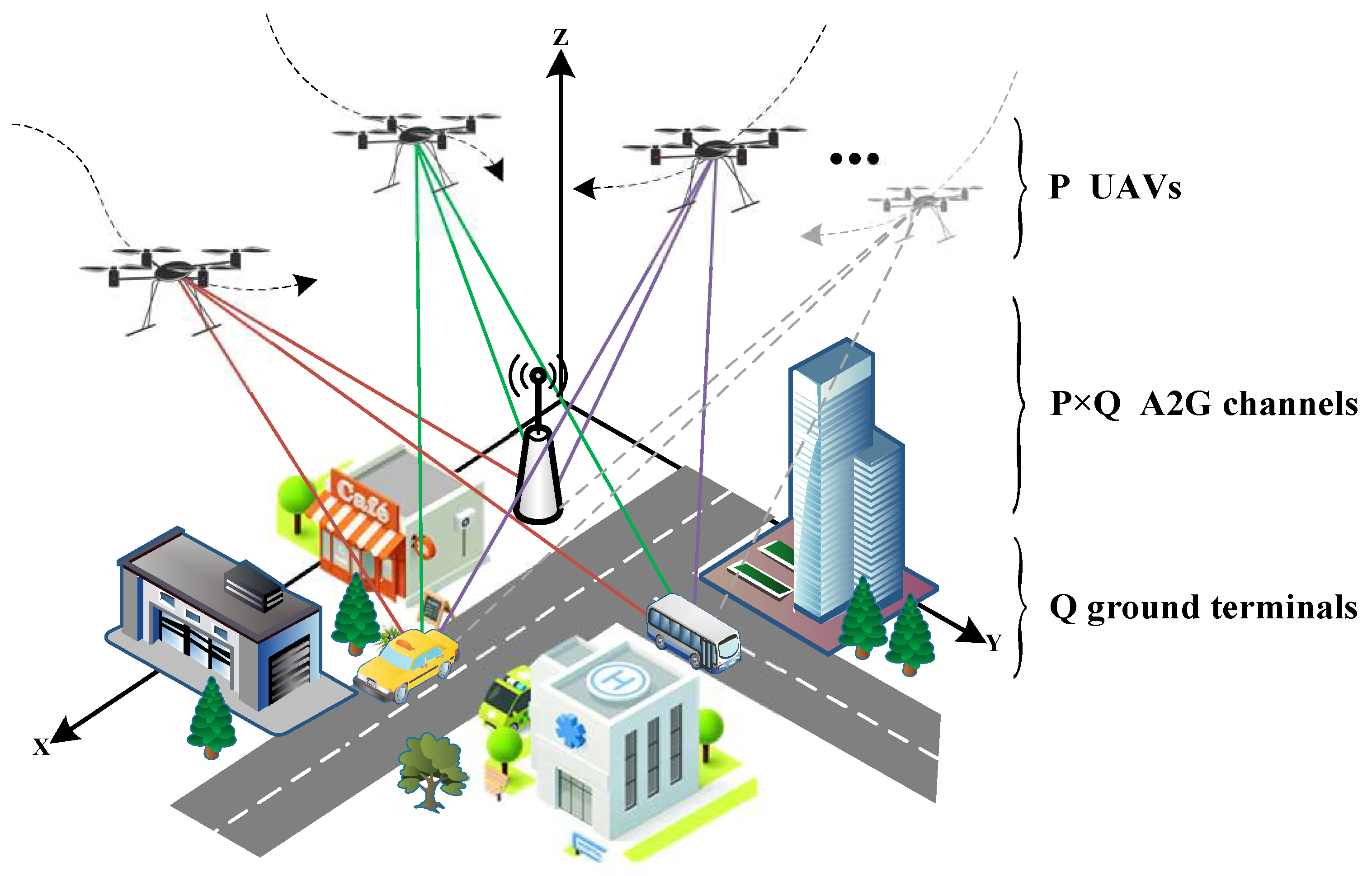
  • A multi-link A2G channel model under urban scenarios is proposed. The channel impulse response (CIR) of each UAV-to-ground link is modeled as spatially variant. A cross-correlation function is adopted to represent the multi-link channel similarity between different spatial positions. And, expressions for the multi-link channel cross-correlation are derived.
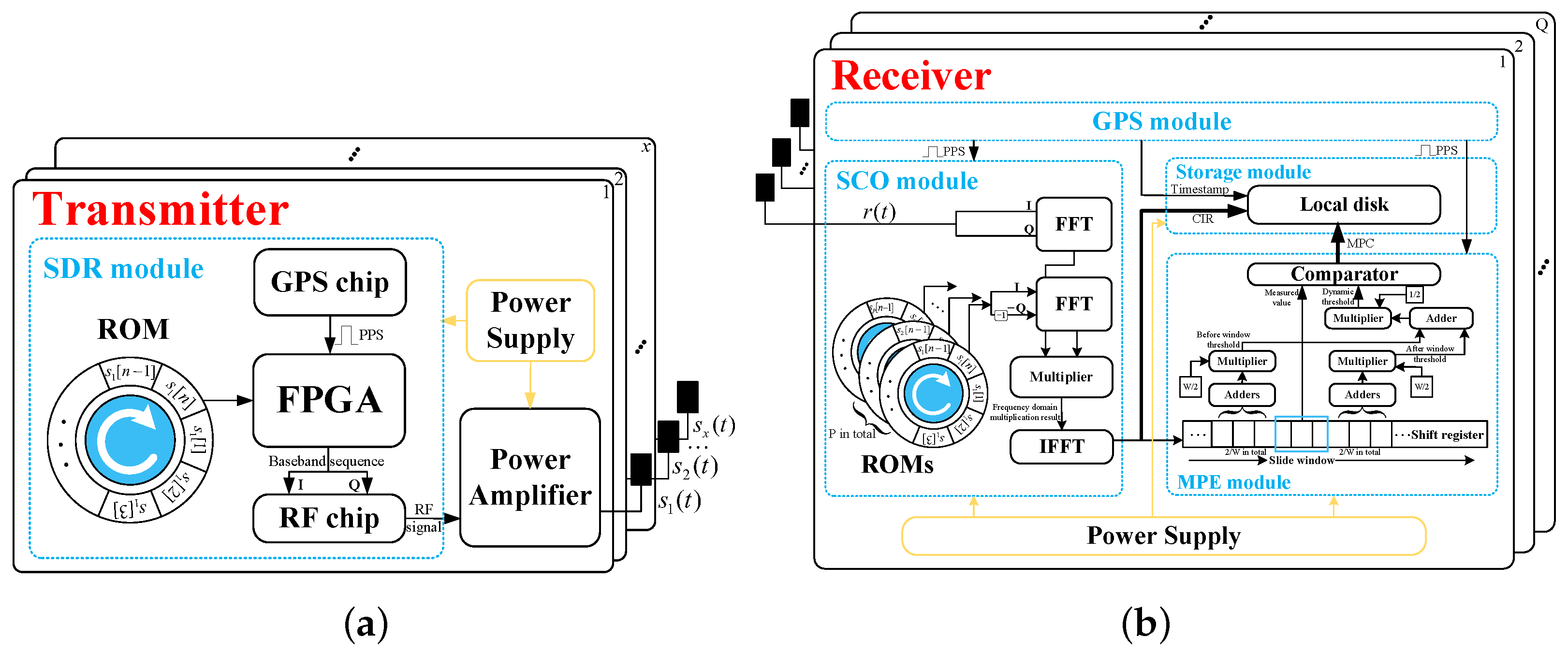
  • A multi-UAV cooperative channel measurement system is developed. In this system, an orthogonal channel measurement signal which can avoid cross-interference between multiple UAVs is specially designed. Some hardware processing algorithms are implemented in a field-programmable gate array (FPGA), which can benefit the accuracy of measurement and reduce the stress of data storage.
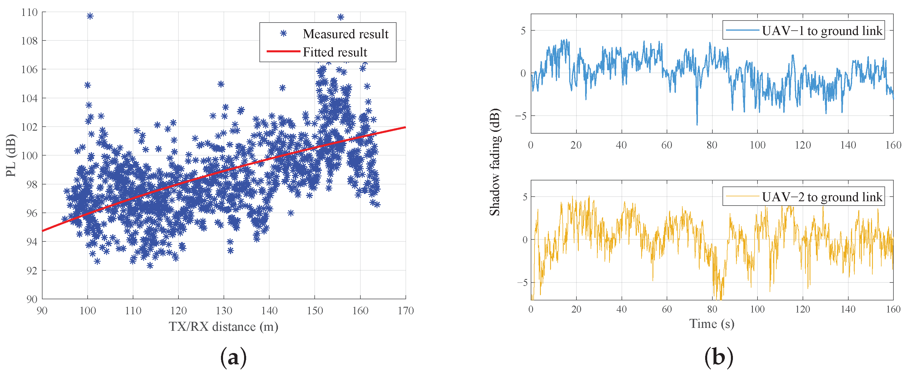
  • Based on the measurement system, a multi-UAV cooperative channel measurement campaign was conducted on a campus at the 3.6 GHz frequency band, and a large number of measurement data were obtained. Based on the measurement data, we analyze the large-scale channel characteristics and the cross-correlation characteristics of channel parameters. The analysis will provide a reference for the design of multi-UAV cooperative communication systems.
The rest of this paper is organized as follows. Section 2 presents the multi-link A2G channel model under an urban scenario. Section 3 introduces the method of multi-UAV cooperative channel measurement, performance evaluation is performed by simulation, and hardware implementation is introduced. In Section 4, a multi-UAV cooperative channel measurement campaign is conducted on the campus, and the large-scale characteristics and cross-correlation characteristics of the channel parameters are analyzed. Finally, conclusions are drawn in Section 5.

2. Multi-Link A2G Channels

Let us consider a low-altitude UAV-aided communication network in an urban scenario, as shown in Figure 1. There are P UAVs communicating with Q ground terminals. These communication nodes move along certain flight trajectories. We set up a three-dimensional (3D) coordinate system, and the time-variant spatial position can be expressed as L ( t ) = { x ( t ) , y ( t ) , z ( t ) } , where x, y, and z represent its coordinates in the 3D space.
Due to different spatial positions, the channel between each UAV-to-ground link is spatially variant. The CIR can be expressed as
h p q ( τ ; L p T , L q R , f , t ) = m = 1 M ( t ) P m ( L p T , L q R , f , t ) δ ( τ τ m ( L p T , L q R , f , t ) )
where h p q ( τ ; L p T , L q R , f , t ) represents the CIR between the p-th TX at position L p T and the q-th ground RX at position L q R at the communication frequency f and time instant t. It is an accumulation of several propagation paths, and M ( t ) denotes the total number of them. P m ( L p T , L q R , f , t ) and τ m ( L p T , L q R , f , t ) denote the time-varying power and delay of each path, respectively, which are determined by L p T , L q R , and f. In a realistic environment, a valid propagation path could be line-of-sight (LoS) or none-LoS (NLoS), i.e., single-, double-, and multiple-bounce paths.
In this paper, we adopt the cross-correlation function to represent the channel similarity between different positions. Let us denote the channel between the p 1 -th UAV and the q 1 -th ground terminal as h m , and the CIR between the p 2 -th UAV and the q 2 -th ground terminal as h n , where p 1 , p 2 ( 1 , P ) , q 1 , q 2 ( 1 , Q ) , and m , n ( 1 , P × Q ) . The PDPs can be expressed as h m 2 and h n 2 , respectively. Thus, the cross-correlation between the PDPs can be expressed as
ρ h m , h n PDP = E [ ( h m 2 h m 2 ¯ ) · ( h n 2 h n 2 ¯ ) ] σ h m 2 · σ h n 2
where E ( · ) represents mathematical expectation, and σ represents standard deviation. In reality, the communication frequency f is usually constant. Therefore, when we study the cross-correlation between two links’ PDPs at the same time t, their cross-correlation values are related to their spatial positions. Understanding the influence of spatial relative distance on the cross-correlation of PDPs will aid in the design of more effective signal processing algorithms to mitigate the effects of multipath propagation, thereby improving the performance of communication systems.
Furthermore, we can obtain the PL, which can be expressed as the accumulation of all path power values as
PL = 10 log 10 ( m = 1 M ( t ) P m ( L p T , L q R , f , t ) )
The PL can be regarded as two parts, namely, the mean value, which represents the overall PL level, and shadowing fluctuations caused by the propagation distance or environmental changes. By removing these mean values, we can obtain the shadowing fluctuations, i.e., SFs. Then, we can obtain the cross-correlation function of shadow fading between channel h m and channel h n as
ρ h m , h n SF = E [ ( S F m S F m ¯ ) · ( S F n S F n ¯ ) ] σ S F m · σ S F n
Analyzing the cross-correlation properties of SF in different channels will help understand the dynamic characteristics of the channels. Based on the decorrelation distance, it will be beneficial to better plan antenna positions and layouts, provide a reference for the application of diverse techniques, and enhance the performance and reliability of communication systems.

3. Multi-UAV Based A2G Channel Measurement System

3.1. Multi-UAV Based Channel Measurement Scheme

Channel measurement is the most accurate way to capture CIR. The overview of the developed multi-UAV cooperative channel measurement system is shown in Figure 2. Multiple UAV transmitters emit specially designed Zadoff–Chu (ZC) sequences cooperatively. Each signal experiences a different wireless propagation process and arrives at the ground RXs. Each ground RX receives signals from multiple UAV transmitters. Then, the CIRs can be extracted from the superimposed received signals by the slide correlation operation (SCO) with local ZC sequence. Finally, based on the measured CIRs, channel characteristics can be further analyzed.

3.2. Implementation of Measurement System

Under the multi-UAV background described in this paper, the process of wireless propagation in Figure 2 can be expressed as
r ( t ) = s ( t ) h P × Q ( τ ; L T , L R , f , t )
where r ( t ) = [ r 1 ( t ) , r 2 ( t ) , , r q ( t ) , , r Q ( t ) ] T represents the vector of the received signal; s ( t ) = [ s 1 ( t ) , s 2 ( t ) , , s p ( t ) , , s P ( t ) ] T represents the vector of the transmitted signal; h P × Q ( τ ; L T , L R , f , t ) is a P × Q matrix, whose element can be expressed as (1), representing the CIR of the p-th UAV and the q-th ground terminal, and ∗ represents the convolution operation.
Therefore, it is vital to extract the CIR of A2G channels by conducting channel measurement. Our channel measurement is based on the time-domain measurement method. It has the advantages of real-time performance and high accuracy, and is a narrow-band pulse measurement scheme that can acquire multipath components (MPCs) without complex data processing. This method obtains CIRs by operating the sliding correlation between the received signal and the standard transmit signal. The signal received by the ground RX is a superposition of multiple transmitted ZC sequences; so, taking obtaining the CIR between the p-th UAV and the q-th ground terminal as an example, the SCO in the ground RX can be expressed as
h p q ( τ ; L T , L R , f , t ) = p = 1 P s p ( t ) h p q ( τ ; L T , L R , f , t ) s p ( t )
where ⊗ represents the SCO. In this way, the CIR between any UAV and ground RX can be obtained from the superposition. Therefore, anti-aliasing performance of the sequence is required. In our previous measurement campaigns, we investigated single-link channel measurements in point-to-point communication cases, such as UAV-to-vehicle, vehicle-to-vehicle, etc. The ZC sequence was selected as the transmitted signal for its good auto-correlation and flat power spectral density [34,35,36]. However, in the multi-UAV application scenario of this paper, multiple UAVs can transmit signals to the ground RXs at the same time; i.e., it is a multi-to-multi communication case. If the signals transmitted by each UAV are consistent, the signals received by the ground terminal are aliased. As a result, the obtained CIRs after SCO are distorted. Therefore, we modified the commonly used ZC sequence, so that it can be applied to multi-UAV cooperative channel measurement without changing its good autocorrelation characteristics. The expression of the ZC sequence is shown as
s n [ l ] = exp ( j π r n l ( l + 1 ) L )
where l = 0 , 1 , , L 1 , and L is the length of the ZC sequence (it must be an odd number); r n is the root index, which is the key to realizing anti-aliasing channel measurement with multiple transmit signals. It should be noted that the value of the root index r n must be smaller than L and prime to L.
To evaluate the performance of measurement sequences and the measurement scheme, we preset three different channels for three pairs of A2G links. The detailed parameters of the simulated channels are listed in Table 1. Three transmitted ZC sequences with root indexes 1, 3, and 5 are used as the signals transmitted by UAVs. After SCO with the cumulative received signal, three CIRs are extracted. We compare the CIRs with the preset channel parameters, as shown in Figure 3.
It can be seen that the three CIRs obtained after SCO have little difference to the preset channel. In terms of multipath power, the obtained multipath power of the three channels is consistent with the preset value, and the difference is very small. We calculate the root mean square error (RMSE) of the SCO results and the preset value, which is 2.3739 dB. In terms of multipath delay, at the sampling rate of 100 MHz, the interval between each sampling point is 1 ns, and the obtained CIRs show that the delay is completely accurate and consistent with the preset channel. The comparison shows that the proposed improved ZC sequence has good anti-aliasing performance in the simulation environment.
It is worth mentioning that taking the ZC sequence of 1024 length as an example, because the root index needs to be mutual prime and less than 1024, the alternative root indexes are 1, 3, 5… 1023, a total of 512. However, in the realistic measurement, the ZC sequences of different root indexes will be summed at the ground RX, the orthogonality is different between different ZC sequences with different root indexes, which directly affects the dynamic range of the measured CIRs. Dynamic range is defined as the ratio of the maximum peak of path power to the maximum floor noise, which can be expressed as
D = max ( p e a k ( h ( τ ) ) ) max p e a k ( h ( τ ) h ( τ ) p e a k ( h ( τ ) )
where max · indicates the operation of finding the maximum value, and p e a k · indicates the operation to find the peak value of all multipath power. Taking two UAVs for collaborative measurement as an example, we set one of the root indexes of the transmitted sequence as 1, and the other one is set as traversing 3, 5, 7… 1023; these two sequences are denoted as sequence-1 and sequence-2, respectively. As shown in Figure 4, the dynamic range of the sequence-1 is affected differently, the mean value of the dynamic range is 87.03 dB, indicating that sequence-2, with different root indexes, does not have much influence on the SCO results of sequence-1, and its dynamic range performance is good in the collaborative measurement of the two UAVs. However, in the worst case, the dynamic range is 24.22 dB, making the NLoS path drowned by the floor noise, seriously affecting the accuracy of multi-UAV channel measurement. In the actual measurement, it is important to choose the appropriate root index.
The hardware architecture of the self-developed aerial TX equipped on each UAV is shown in Figure 5a. It consists of a power supply, power amplifier (PA), antenna, and a software-defined radio (SDR) module with FPGA chip, radio-frequency (RF) chip, and Global Positioning System (GPS) chip. The ZC sequence with specific root indexes is pre-stored in the read-only memory (ROM) of the SDR module in each TX, and the module is triggered by the pulse-per-second (PPS) signal received by the GPS chip. Whenever the PPS trigger signal is received, the FPGA chip outputs the sequence to the RF chip and the RF chip carries the baseband signal to the specified carrier frequency. The PA greatly increases the power of the signal and radiates to the space through the antenna. Based on the Verilog hardware design language (HDL), we implement the TX algorithms on a Xilinx Zynq-7000 chip series FPGA chip of AMD (Santa Clara, CA, USA), manufactured in Taiwan and purchased in China. The 16-bit-wide I/Q sounding sequences are stored in ROM with a depth of 1024. Triggered by the PPS from the GPS chip, the baseband sounding sequences will be outputted to the RF chip through the advanced extensible interface (AXI), up-converted to the specific measurement frequency band, and finally, the PA greatly increases the power of the sequences and radiates to the space through the omnidirectional antenna.
The hardware architecture of the ground RX is shown in Figure 5b. The same as the TX, the RX is triggered by the PPS signal received by the GPS module. Once the antenna receives the signal from the TX, the SCO module in the FPGA starts to work. The module pre-stores the standard ZC sequences, which are consistent with the ones transmitted by each UAV; they are used to perform SCO based on fast Fourier transform (FFT) with the received signal to obtain the time-varying CIRs between the UAVs and the ground RX. Then, the obtained CIRs enter the multipath extraction (MPE) module. We propose a hardware MPE algorithm based on a constant false alarm rate (CFAR) to effectively extract the MPCs in CIRs [37]. Finally, the CIRs, MPCs, and the timestamp are packaged and stored locally by the data storage module. These hardware algorithms can help achieve real-time channel measurement and guarantee the accuracy and efficiency of the measurement [35]. The algorithms at the RX are also based on Verilog HDL, and we implement the algorithms on a Xilinx Kintex-7 410T chip (series FPGA chip of AMD (Santa Clara, CA, USA). It is the core processing unit of the integrated data processing module assembled by National Instruments (NI) and purchased from professional distributors in China). Because of the complexity of the convolution operation, it is difficult to implement in FPGA efficiently. We convert convolution operations in the time domain into multiplication operations in the frequency domain to implement SCO. Then, we need to extract the effective multipath component of CIR. We adopt a dynamic threshold MPE algorithm based on a CFAR method. Based on a sliding window, continuous CIR data are stored in the shift register. The algorithm generates a dynamic threshold based on the CIR data before and after the sliding window, and outputs the threshold value to the comparator, and the samples above this threshold are considered valid MPCs. Finally, the CIR, MPC, and timestamp are transferred to the data storage module via the peripheral component interconnect express (PCIE) bus.

3.3. Channel Characteristics Acquisition

Through the above measurement system, we are able to obtain a large number of measurement data, including CIRs, MPCs, and timestamps. We need to further process the data to obtain the channel characteristics. Firstly, we can obtain the PDP, which is regarded as the squaring of the absolute value of the CIR, and can be described as autocorrelation characteristics. The expression for the PDP can be expressed as
PDP ( τ ; L T , L R , f , t ) = h ( τ ; L T , L R , f , t ) 2 = m = 1 M ( t ) P m ( L T , L R , f , t ) δ ( τ τ m ( L T , L R , f , t ) )
where · denotes the absolute value.
After that, in order to further study the large-scale characteristics of channels, we need to eliminate the effect of small-scale fading by an averaging method. Assuming we are measuring at a sampling rate of r, the interval between each sampling point is 1 / r . Therefore, for a ZC sequence of 1024 in length, the length of the PDP snapshot is also 1024, and occupies 1024 × 1 / r . Next, we average several snapshots, assuming that the number of snapshots being averaged is n, then this represent the large-scale characteristics of the channel at a time interval of n × 1024 × 1 / r . In practice, we need to control the average number of snapshots (which is determined by the carrier frequency, motion speed, etc.), so that the averaged PDPs can represent the large-scale characteristics well.
After obtaining the averaged PDP, we can further obtain the PL. PL is defined as the ratio of transmit power to receive power, which is important for the link budget of UAV communication and is an important parameter to describe the large-scale effect of the propagation channel. In the former part of the paper, we introduce the multipath extraction method by CFAR, so that the PL can be obtained from the multipath as (3). Then, the close-in (CI) model [38] is used to fit the PL values and obtain the shadow fading. The CI model is expressed as
P L CI ( d , f ) = P L FS ( d 0 , f ) + 10 n log 10 ( d d 0 ) + X λ
where P L F S ( d 0 , f ) denotes the free-space PL (FSPL) model at the reference distance d 0 (set as 1 m in this case) and the carrier frequency f, n is the PL exponent (PLE), and d is the link distance. X λ is a random variable used to model the SF, which follows the zero-mean normal distribution with a standard deviation of λ . The FSPL model mentioned above is expressed as
P L FS ( d , f ) = 20 log 10 ( d ) + 20 log 10 ( f ) + 32.45

4. Measurement Results and Analysis
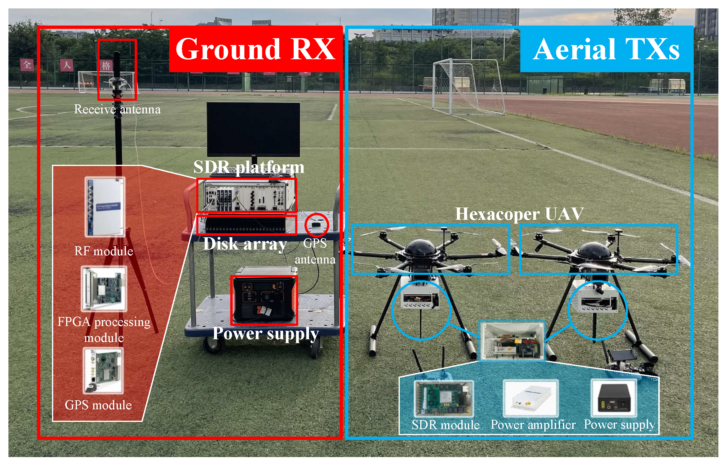
4.1. System Setup

The developed multi-UAV cooperative channel measurement system is shown in Figure 6. Due to the limitation of the experimental conditions, we take two UAV-aided aerial TXs and a ground RX as an example case. However, most of the work in this paper is general for multiple UAVs, such as channel models and hardware frameworks. In order to minimize the influence caused by the inherent structure of the UAV, the aerial TXs were installed vertically below the UAVs, powered individually by lithium batteries. The self-developed SDR module (consisting of FPGA chip, RF chip, and GPS chip) can transmit the measurement signal by the trigger of PPS, with a baseband bandwidth of 61.44 MHz; the PA is adopted with a gain of 42 dB, and the total transmit power is 32 dBm. The ground RX is developed based on the SDR platform (consisting of data process module, RF module, and GPS module). The platform is able to sample data with a bandwidth of 100 MHz; the algorithms run on the FPGA chip in real time. Due to the high speed and continuity of the measurement data, they are stored in a high-performance disk array with a data rate up to 3.6 GB/s and capacity of 24 TB. The RX is also triggered by the PPS. Each TX/RX uses the same omnidirectional antenna, which has an approximately omni-azimuthal pattern and a 120-degree elevation pattern at half-power beam width (HPBW); the antenna gain is 3 dBi at 3.6 GHz. Some system setups can be found in Table 2. More details about the hardware components can also be found in [35].

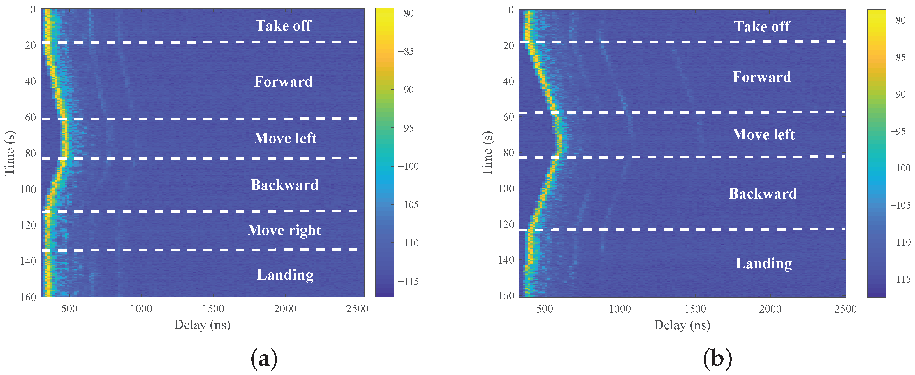
4.2. Measurement Campaigns

The measurement campaign was carried out on the campus, as shown in Figure 7. The scenario contained buildings, playground, roads, and trees. The buildings were between 15 and 40 m in height, with a combination of sparsely distributed tall trees (no more than 4 m) and low shrubs around the buildings. From the height of the buildings and the density of plants in the environment, it is a typical suburban environment.
Considering the potential role that UAVs can play in 5G and joint communication and sensing of 6G in the future, we chose 3.6 GHz, a commonly used communication frequency band for our measurement campaign. It should be mentioned that the research methodology of this paper is general for any frequency band. We only chose 3.6 GHz as an example case. The sampling rate of the TX/RX was 100 MHz, the sequence length of the TXs was 1024, and the root indexes were set to 1 and 3.
During the measurement, two UAVs took off from the playground at the same time, carrying aerial TXs. Each UAV flew along a certain trajectory at a constant speed of 1 m/s. The flight height of UAV-1 was 18 m and that of UAV-2 was 15 m; these remained unchanged throughout the flight. Finally, both UAVs landed at the playground at the same time, completing the entire measurement process. The ground RX was located among the buildings to receive signals from each aerial TX and further processing algorithms, the height of the receive antenna was set at 2 m, and the straight distance between the TX and RX was from 95 to 165 m.

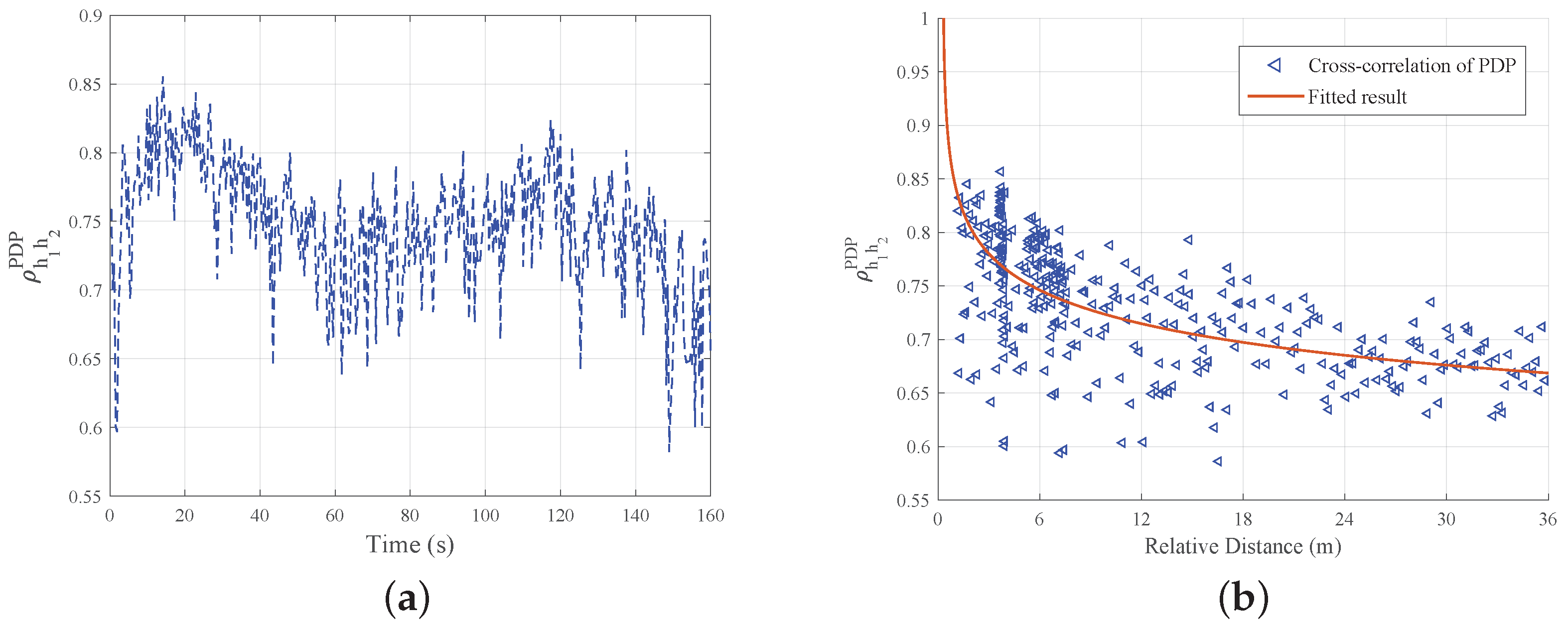
4.3. Channel Cross-Correlation Characteristics

Based on the multi-UAV cooperative channel measurement campaign described in the previous section, we obtained a large number of measurement data, namely, CIRs and MPCs, as well as the corresponding geographical locations and timestamps. We obtained the PDPs by (9), and the interval of each instantaneous PDPs slice was about 16.7 μ s when the sampling rate was set as 61.44 MHz. We averaged instantaneous slices to obtain the average PDPs to eliminate the effect of small-scale effect caused by random factors and noise, and each PDPs slice was an average of 60 consecutive instantaneous PDPs.
The measured time-varying PDPs along the whole trajectories of the two aerial TXs are shown in Figure 8, noting that all antenna gains and cable losses have been eliminated during data processing. As shown, effective multipaths are densely distributed near the main path, the NLoS case occurs throughout the measurement, and obvious birth–death phenomena of multipaths can be observed. For the sake of expression, we divide the trajectories into several stages, namely, take-off, forward, move left, move right, backward, and landing. It can be seen that in the process of take-off/landing, the scattering paths are relatively chaotic, which is in line with the actual scenario, because the flight height in these two stages is low, and the propagation path is blocked. The measured PDPs of UAV-1 are shown in Figure 8a; as the straight distance between the TX and RX is from 95 m to 130 m, the theoretical absolute path delay is about 316.67∼433.33 ns. It can be found that the measured path delay values are in good agreement with the theoretical ones. Two obvious scattering paths can be observed in the whole measurement process. According to the estimation of relative delay with the main path, the propagation distances of these two scattering paths are about 85 m and 150 m, which are speculated to be the scattering paths caused by the reflections of surrounding buildings. As for UAV-2, the measured PDP is shown in Figure 8b, the measured path delay values are also comparable to the theoretical values. Similar to the case of UAV-1, we are able to observe a scattering path, which arises during the TX move forward stage and gradually disappears after the TX move left stage.
Because of the particularity of multi-UAV collaborative channel measurement, the measurement signals from different UAVs are affected by the similar wireless propagation environment, resulting in the correlation of each communication link at the large scale. We apply each time-varying PDP snapshot in (2), and obtain the cross-correlation coefficient of the PDP between two links, as is shown in Figure 9.
It can be found from Figure 9a that there is a high correlation between the two measured PDPs, with a mean value of 0.7458. According to the changing trend in the cross-correlation coefficient, we can indicate that when two UAVs are in a similar flight phase, namely, when the relative spatial position of the two UAVs is basically constant, the cross-correlation values appear constant or rising, but when the UAVs are in different flight phases, such as moving in two different directions, the correlation coefficient decreases or experiences large fluctuations. In existing studies, the relationship between cross-correlation and relative distance between multi-link PDPs has not been widely discussed; we further analyze the relationship as shown in Figure 9b. It can be found that when the relative distance between two UAVs is smaller than about 8 m, the cross-correlation value remains mainly at a high level (around 0.75∼0.8), and shows a downward trend when the relative distance between two UAVs becomes larger. In order to quantitatively describe the relationship between them, we used an exponential fitting model, expressed as
ρ ( Δ d ) = a · Δ d b
where Δd represents the relative distance, a and b denote the model parameters, and are fitted to be 0.8572 and −0.0598, respectively. It can be indicated that when the cross-correlation value reduced to 0.707 (i.e., 3 dB), the corresponding relative distance was 14.765 m, which is denoted as the decorrelation distance of c.
Next, we obtain the measured PL values using (3), and the CI model is used to fit the measured PL according to (10) and (11). The fitting results are shown in Figure 10a; the fitted PLE n is 2.618. Compared with the values of the PLE, n ranges from 2.2 to 2.9 in [28] and ranges from 2.64 to 2.76 in [39], which are similar to the value in our measurements. Based on these, we further obtained the SF of the two A2G links by subtracting the measured PL values from the fitted values of the CI model. The SFs of the two links are shown in Figure 10b.
The cross-correlation of SFs are important for the power control and positioning design of UAV-assisted multi-link communication systems. According to the stationary interval, we define a sliding window used to divide the SF into several consecutive slices, and calculate the cross-correlation coefficient between the slices corresponding to two links. As shown in Figure 11a, compared with the PDP the cross-correlation values of the SF are relatively small, and the mean value is 0.2665. In addition, the values of the cross-correlation experience large fluctuations, we believe that, though the multi-UAV cooperative channel measurement is performed simultaneously, the obstacles randomly appearing in the measurement may be different and have a large impact on the SFs of different links. As for the cross-correlation of SFs with respect to the relative distance in Figure 11b, a downward trend can be observed when the relative distance increases. A single-exponential model is established to model the cross-correlation of SFs, which is given as
ρ exp ( Δ d ) = exp ( Δ d d c o r )
where d c o r represents the decorrelation distance, d c o r = d ( 1 / e ) is used to evaluate the decorrelation distance at which ρ drops to 1 / e , and we find it is 4.628 m in our measurement.
From our analysis results, it can be found that the cross-correlation between PDPs remains at a high level, which is a remarkable feature. The cross-correlation between SFs is relatively insignificant, partial anti-correlation can also be observed; we believe that, though the cooperative channel measurement is performed simultaneously in the same scenario, the obstacles randomly appearing may differ and have a large impact on the SF of the two links. These findings can provide important references for the design of future UAV-assisted wireless communication systems.

5. Conclusions

In this paper, we have established a multi-link A2G channel model of multi-UAV-to-ground communication, introduced a method of multi-UAV cooperative channel measurement, verified the feasibility, and evaluated the measurement performance in a simulation environment. We have developed a multi-UAV channel measurement system according to the proposed measurement scheme. Then, as a typical case of multi-UAV cooperative channel measurement system, two aerial TXs and a ground RX have been used to conduct channel measurement on a campus at 3.6 GHz to investigate the large-scale characteristics of the two UAVs to ground channels, including PDP, PL, and SF. The cross-correlation of the PDP and SF are obtained. The decorrelation distance is found to be 14.765 m for the PDP, and 4.628 m for SF. These findings can be used to optimize the communication efficiency of multi-UAV-to-ground communication systems, path planning of multi-UAV cooperative communication, and channel modeling of multi-link communication. In the future, we plan to build more air TXs and ground RXs to carry out multi-UAV channel measurement. Moreover, we plan to improve the integration of TX/RX to facilitate its deployment, and realize channel measurement campaigns in different application scenarios. These improvements will help us obtain more valuable channel characteristics.

Author Contributions

Conceptualization, X.Y. and Q.Z.; funding acquisition, Q.Z. and X.C.; investigation, K.M. and X.Y.; methodology, X.Y. and K.M.; software, H.L. (Hangang Li) and H.L. (Hanpeng Li); data acquisition, X.Y., H.L. (Hangang Li) and H.L. (Hanpeng Li); supervision, Q.Z., X.C. and W.Z.; validation, B.H.; writing—original draft, X.Y. and Q.Z.; writing—review and editing, X.Y., H.L. (Hanpeng Li) and K.M.; visualization, X.Y.; supervision, Q.Z. All authors have read and agreed to the published version of the manuscript.

Funding

This work was supported in part by the National Natural Science Foundation of China under No. 62271250 and No. U23B2005, in part by the Key Technologies R&D Program of Jiangsu (Prospective and Key Technologies for Industry) under Nos. BE2022067, and BE2022067-3, BE2022067-1.

Data Availability Statement

The datasets collected and generated in this study are available upon request to the corresponding author.

Acknowledgments

We would like to express our sincere thanks to all the editors, reviewers and staff who participated in the review of this article.

Conflicts of Interest

The authors declare no conflicts of interest.

References

  1. Hayat, S.; Yanmaz, E.; Muzaffar, R. Survey on Unmanned Aerial Vehicle Networks for Civil Applications: A Communications Viewpoint. IEEE Commun. Surv. Tutor. 2016, 18, 2624–2661. [Google Scholar] [CrossRef]
  2. Silvagni, M.; Tonoli, A.; Zenerino, E.; Chiaberge, M. Multipurpose UAV for Search and Rescue Operations in Mountain Avalanche Events. Geomat. Nat. Hazards Risk 2016, 8, 18–333. [Google Scholar] [CrossRef]
  3. Mozaffari, M.; Saad, W.; Bennis, M.; Nam, Y.H.; Debbah, M. A Tutorial on UAVs for Wireless Networks: Applications, Challenges, and Open Problems. IEEE Commun. Surv. Tutor. 2019, 21, 2334–2360. [Google Scholar] [CrossRef]
  4. Pan, J.; Ye, N.; Yu, H.; Hong, T.; AI-Rubaye, S.; Mumtaz, S.; AI-Dulaimi, A.; Chih-Lin, I. AI-Driven Blind Signature Classification for IoT Connectivity: A Deep Learning Approach. IEEE Trans. Wirel. Commun. 2022, 21, 6033–6047. [Google Scholar] [CrossRef]
  5. You, X.; Wang, C.X.; Huang, J.; Gao, X.; Zhang, Z.; Wang, M.; Huang, Y.; Zhang, C.; Jiang, Y.; Wang, J.; et al. Towards 6G Wireless Communication Networks: Vision, Enabling Technologies, and New Paradigm Shifts. Sci. China Inf. Sci. 2021, 64, 1–74. [Google Scholar] [CrossRef]
  6. Jiang, H.; Zhang, Z.; Wang, C.-X.; Zhang, J.; Dang, J.; Wu, L.; Zhang, H. A Novel 3D UAV Channel Model for A2G Communication Environments Using AoD and AoA Estimation Algorithms. IEEE Trans. Commun. 2020, 68, 7232–7246. [Google Scholar] [CrossRef]
  7. Mao, K.; Zhu, Q.; Song, M.; Li, H.; Ning, B.; Pedersen, G.F.; Fan, W. Machine Learning-based 3D Channel Modeling for U2V mmWave Communications. IEEE Int. Things J. 2022, 9, 17592–17607. [Google Scholar] [CrossRef]
  8. Hua, B.; Zhou, T.; Zhu, Q.; Mao, K.; Bao, J.; Zhong, W. A Realistic 3D Non-stationary Channel Model for UAV-to-vehicle Communications Incorporating Fuselage Posture. China Commun. 2023, 20, 277–290. [Google Scholar] [CrossRef]
  9. Zeng, L.; Liao, X.; Xie, W.; Ma, Z.; Xiong, B.; Jiang, H. UAV-to-Ground Channel Modeling: (Quasi-)Closed-Form Channel Statistics and Manual Parameter Estimation. China Commun. 2024. early access. [Google Scholar] [CrossRef]
  10. Ni, H.; Zhu, Q.; Hua, B.; Mao, K.; Pan, Y.; Ali, F.; Zhong, W.; Chen, X. Path Loss and Shadowing for UAV-to-Ground UWB Channels Incorporating the Effects of Built-Up Areas and Airframe. IEEE Intell. Transp. Syst. 2024. early access. [Google Scholar] [CrossRef]
  11. Jiang, H.; Zeng, Z.; Wu, L.; Dang, J. Three-Dimensional Geometry-Based UAV-MIMO Channel Modeling for A2G Communication Environments. IEEE Commun. Lett. 2018, 22, 1438–1441. [Google Scholar] [CrossRef]
  12. Na, Z.; Liu, Y.; Shi, J.; Liu, C.; Gao, Z. UAV-Supported Clustered NOMA for 6G-Enabled Internet of Things: Trajectory Planning and Resource Allocation. IEEE Int. Things J. 2021, 8, 15041–15048. [Google Scholar] [CrossRef]
  13. Ma, Z.; Ai, B.; He, R.; Mi, H.; Yang, M.; Wang, N.; Zhong, Z.; Fan, W. Modeling and Analysis of MIMO Multipath Channels with Aerial Intelligent Reflecting Surface. J. Select. Areas Commun. 2022, 40, 3027–3040. [Google Scholar] [CrossRef]
  14. Shi, M.; Yang, K.; Niyato, D.; Yuan, H.; Zhou, H.; Xu, Z. The Meta Distribution of SINR in UAV-Assisted Cellular Networks. IEEE Trans. Commun. 2023, 71, 1193–1206. [Google Scholar] [CrossRef]
  15. Jiang, H.; Xiong, B.; Zhang, H.; Basar, E. Physics-based 3D End-to-End Modeling for Double-RISs Assisted Non-stationary UAV-to-ground Communication Channels. IEEE Trans. Commun. 2023, 71, 4247–4261. [Google Scholar] [CrossRef]
  16. Hua, B.; Ni, H.; Zhu, Q.; Wang, C.-X.; Zhou, T.; Mao, K.; Bao, J.; Zhang, X. Channel Modeling for UAV-to-Ground Communications with Posture Variation and Fuselage Scattering Effect. IEEE Trans. Commun. 2023, 71, 3103–3116. [Google Scholar] [CrossRef]
  17. Lian, Z.; Wang, Y.; Su, Y.; Ji, P.; Ling, L.; Zhang, Z.; Jin, B.; Luo, H. A Novel Beam Channel Model and Capacity Analysis for UAV-enabled Millimeter-Wave Communication Systems. IEEE Wirel. Commun. 2024, 23, 3617–3632. [Google Scholar] [CrossRef]
  18. Mao, K.; Zhu, Q.; Wang, C.-X.; Ye, X.; Ponce, J.G.; Cai, X.; Miao, Y.; Cui, Z.; Wu, Q.; Fan, W. A Survey on Channel Sounding Technologies and Measurements for UAV-Assisted Communications. IEEE Trans. Instrum. Meas. 2024. early access. [Google Scholar] [CrossRef]
  19. Matolak, D.W.; Sun, R. Air–ground Channel Characterization for Unmanned Aircraft Systems—Part III: The Suburban and Near-urban Environments. IEEE Trans. Veh. Technol. 2017, 66, 6607–6618. [Google Scholar] [CrossRef]
  20. Khawaja, W.; Ozdemir, O.; Erden, F.; Guvenc, I.; Matolak, D.W. Ultra-wideband Air-to-ground Propagation Channel Characterization in an Open Area. IEEE Trans. Aerosp. Electron. Syst. 2020, 56, 4533–4555. [Google Scholar] [CrossRef] [PubMed]
  21. Yu, C.; Liu, Y.; Chang, H.; Zhang, J.; Zhang, M.; Poechmueller, P.; Wang, C.X. AG Channel Measurements and Characteristics Analysis in Hilly Scenarios for 6G UAV Communications. China. Commun. 2022, 19, 32–46. [Google Scholar] [CrossRef]
  22. Wang, J.; Zhu, Q.; Lin, Z.; Wu, Q.; Huang, Y.; Cai, X.; Zhong, W.; Zhao, Y. Sparse Bayesian Learning-Based 3D Radio Environment Map Construction—Sampling Optimization, Scenario-Dependent Dictionary Construction and Sparse Recovery. IEEE Trans. Cogn. Commun. Netw. 2024, 10, 80–93. [Google Scholar] [CrossRef]
  23. Wang, J.; Zhu, Q.; Lin, Z.; Chen, J.; Ding, G.; Wu, Q.; Gu, G.; Gao, Q. Sparse Bayesian Learning-Based Hierarchical Construction for 3D Radio Environment Maps Incorporating Channel Shadowing. IEEE Wirel. Commun. 2024. early access. [Google Scholar] [CrossRef]
  24. Zhang, C.; Yao, W.; Zuo, Y.; Gui, J.; Zhang, C. Multi-Objective Optimization of Dynamic Communication Network for Multi-UAVs System. IEEE Trans. Veh. Technol. 2024, 73, 4081–4094. [Google Scholar] [CrossRef]
  25. Wang, X.; Fei, Z.; Zhang, J.A.; Huang, J.; Yuan, J. Constrained Utility Maximization in Dual-Functional Radar-Communication Multi-UAV Networks. IEEE Trans. Commun. 2021, 69, 2660–2672. [Google Scholar] [CrossRef]
  26. Wang, L.; Zhang, H.; Guo, S.; Yuan, D. Deployment and Association of Multiple UAVs in UAV-Assisted Cellular Networks With the Knowledge of Statistical User Position. IEEE Wirel. Commun. 2022, 21, 6553–6567. [Google Scholar] [CrossRef]
  27. Bai, L.; Huang, Z.; Feng, T.; Cheng, X. A Non-Stationary Channel Model for 6G Multi-UAV Cooperative Communication. IEEE Wirel. Commun. 2024, 23, 949–961. [Google Scholar] [CrossRef]
  28. Lyu, Y.; Wang, W.; Rashdan, I. Measurement-based Fading Characteristics Analysis and Modeling of UAV to Vehicles Channel. Veh. Commun. 2023, 45, 100707. [Google Scholar] [CrossRef]
  29. Lyu, Y.; Wang, W.; Sun, Y.; Yue, H.; Chai, J. Low-Altitude UAV Air-to-Ground Multilink Channel Modeling and Analysis at 2.4 and 5.9 GHz. IEEE Antennas Wirel. Propag. Lett. 2023, 22, 2135–2139. [Google Scholar] [CrossRef]
  30. Hoellinger, J.; Makhoul, G.; D’Errico, R.; Marsault, T. Channel Correlation and Stationarity in mm-wave V2V Channels. In Proceedings of the 2023 European Conference on Antennas and Propagation (EuCAP), Florence, Italy, 26–31 March 2023; pp. 1–5. [Google Scholar] [CrossRef]
  31. He, R.; Renaudin, O.; Kolmonen, V.; Haneda, K.; Zhong, Z.; Ai, B.; Oestges, C. Characterization of Quasi-Stationarity Regions for Vehicle-to-Vehicle Radio Channels. IEEE Trans. Antennas Propag. 2015, 63, 2237–2251. [Google Scholar] [CrossRef]
  32. Zhou, T.; Tao, C.; Liu, L.; Liu, K. Investigation of Cross-correlation Characteristics for Multi-link Channels in High-speed Railway Scenarios. China Commun. 2018, 15, 108–117. [Google Scholar] [CrossRef]
  33. Zhang, X.; He, R.; Yang, M.; Ai, B.; Wang, S.; Li, W.; Sun, W.; Li, L.; Huang, P.; Xue, Y. Measurements and Modeling of Large-Scale Channel Characteristics in Subway Tunnels at 1.8 and 5.8 GHz. IEEE Antennas Wirel. Propag. Lett. 2023, 22, 561–565. [Google Scholar] [CrossRef]
  34. Zhang, D.; Ai, B.; Fei, D.; Chen, Z. Comparison of Different Sounding Waveforms for a Wideband Correlation Channel Sounder. In Proceedings of the 2021 International Conference on Electronic Information Technology and Radio Technology (EITRT), Qingdao, China, 22–24 October 2021; pp. 119–126. [Google Scholar] [CrossRef]
  35. Mao, K.; Zhu, Q.; Qiu, Y.; Liu, X.; Song, M.; Fan, W.; Kokkeler, A.; Miao, Y. A UAV-Aided Real-Time Channel Sounder for Highly Dynamic Nonstationary A2G Scenarios. IEEE Trans. Instrum. Meas. 2023, 72, 6504515. [Google Scholar] [CrossRef]
  36. Ding, X.; Zhou, K.; Li, G.; Yang, K.; Gao, X.; Yuan, J.; An, J. Customized Joint Blind Frame Synchronization and Decoding Methods for Analog LDPC Decoder. IEEE Trans. Commun. 2024, 72, 756–770. [Google Scholar] [CrossRef]
  37. Ovchinnikov, V.V.; Ryabova, N.V.; Elsukov, A.A. Adaptive HF Signal Detection Algorithm CFAR and Its Verification By Means of SDR Based Digital Ionosonde with USRP Platform. In Proceedings of the 2018 International Conference on Synchronization and Information Processing (SYNCHROINFO), Minsk, Belarus, 4–5 July 2018; pp. 1–5. [Google Scholar] [CrossRef]
  38. Rappaport, T.S. Wireless Communications: Principles and Practice, 2nd ed.; Prentice Hall: Upper Saddle River, NJ, USA, 2002. [Google Scholar]
  39. Qiu, Z.; Chu, X.; Calvo-Ramirez, C.; Briso, C.; Yin, X. Low Altitude UAV Air-to-Ground Channel Measurement and Modeling in Semiurban Environments. Wirel. Commun. Mob. Comput. 2017, 2017, 1587412. [Google Scholar] [CrossRef]
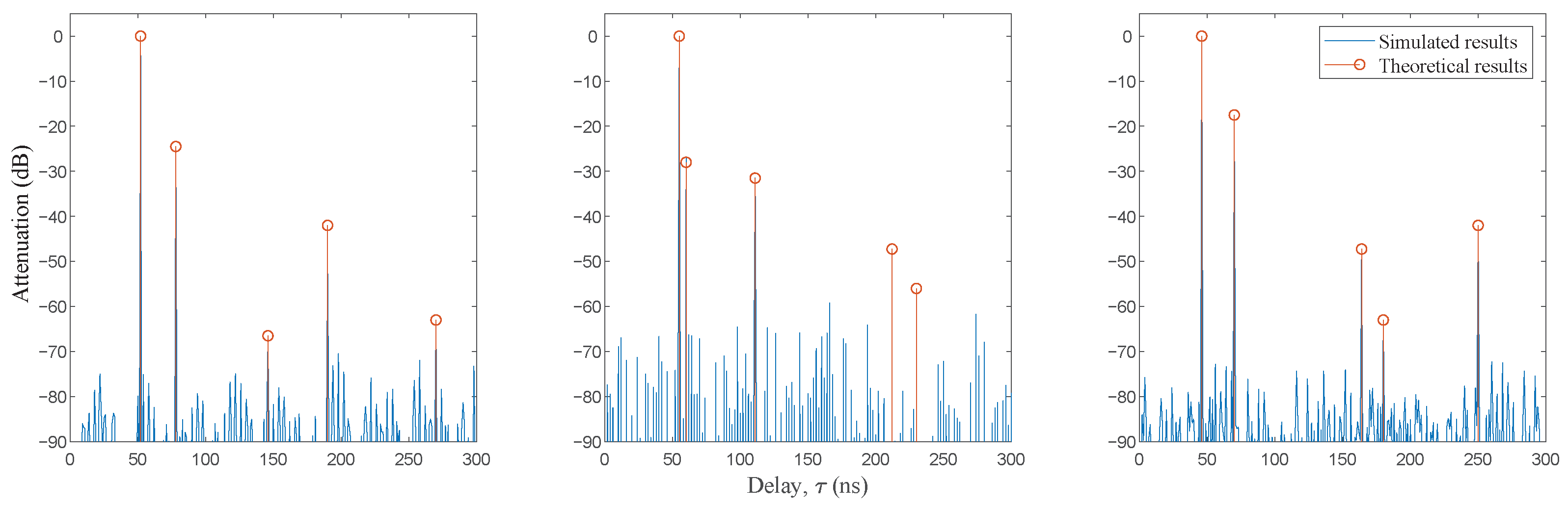
Figure 1. Multi-link A2G communications in urban scenarios.
Drones 08 00416 g001
Figure 2. Overview of multi-UAV channel measurement.
Drones 08 00416 g002
Figure 3. SCO simulation with three preset channels.
Drones 08 00416 g003
Figure 4. Dynamic range of ZC sequence with different rood index.
Drones 08 00416 g004
Figure 5. Hardware architecture of (a) aerial TX and (b) ground RX.
Drones 08 00416 g005
Figure 6. Multi-UAV cooperative channel measurement system.
Drones 08 00416 g006
Figure 7. Field measurements with two UAVs under the campus scenario.
Drones 08 00416 g007
Figure 8. Time-varying PDPs of (a) UAV-1 and (b) UAV-2.
Drones 08 00416 g008
Figure 9. Cross-correlation of PDPs between two links with (a) time and (b) relative distance.
Drones 08 00416 g009
Figure 10. (a) Measured and fitted PLs with communication distances, and (b) SFs of two A2G links.
Drones 08 00416 g010
Figure 11. Cross-correlation of SF between two links with (a) time and (b) relative distance.
Drones 08 00416 g011
Table 1. Parameters of preset channels.
Channel ParametersTap 1Tap 2Tap 3Tap 4Tap 5
Channel-1Delay (ns)5278146190270
Attenuation (dB)0−24.5−66.5−42−63
Channel-2Delay (ns)5560111212230
Attenuation (dB)0−28−31.5−47.26−56
Channel-3Delay (ns)4670164180250
Attenuation (dB)0−17.55−47.23−63−42
Simulation sample rate: 100 MHz
ZC sequence length: 1024
Table 2. System parameters.
System ComponentsFeatures
Aerial
TX
Hexacoper UAVMaximum payload: 5 kg
SDR moduleFrequency range: 75–6000 MHz
Bandwidth: 61.44 MHz
Accuracy of GPS PPS: 20 ns
Power amplifierFrequency range: 600–6000 MHz
Gain: 42 dB
Power supplyBattery Capacity: 44,800 mAh
Output voltage: DC 24/12/5 V
Omnidirectional antennaFrequency range: 3200–3900 MHz
Gain: 3 dBi
Ground
RX
SDR platformData process moduleData processing rate: 6.6 GB/s
RF ModuleFrequency range: 200–4400 MHz
Bandwidth: 100 MHz
GPS moduleAccuracy of GPS 1PPS: 15 ns
Omnidirectional antennaFrequency range: 3200–3900 MHz
Gain: 3 dBi
High-rate disk arrayDisk capacity: 24 TB
Data transferring rate: 3.6 GB/s
Power supplyBattery Capacity: 23.2 Ah
Output voltage: AC 220 V
Disclaimer/Publisher’s Note: The statements, opinions and data contained in all publications are solely those of the individual author(s) and contributor(s) and not of MDPI and/or the editor(s). MDPI and/or the editor(s) disclaim responsibility for any injury to people or property resulting from any ideas, methods, instructions or products referred to in the content.

