1. Introduction
In recent years, unmanned aerial vehicles (UAVs) have been rapidly advancing due to their significant practical value. Compared to rotor UAVs, fixed-wing UAVs exhibit characteristics such as high speed, good weight-bearing capacity, and extended range. They are capable of cruising over a target area and performing various tasks such as surveillance, reconnaissance, targeting, combat damage assessment, communication relay, and even target attack when loaded with ammunition. In particular, miniature fixed-wing UAVs are more suitable for large-scale swarm deployment due to their miniaturization, cost-effectiveness, and user-friendly nature [
1]. By upgrading simple components to achieve coordinated networking, they can transition from a single task unit to a coordinated multi-UAV swarm. Miniature fixed-wing UAVs offer numerous advantages for civilian and military applications. In the civilian sector, UAV swarms can be equipped with various sensors to execute intricate missions. In combat situations, coordinated multi-UAV attacks not only address the ineffectiveness of single missile strikes but also enable saturation attacks and enhance defense-penetration capabilities while leveraging the flexibility of UAVs [
2]. It is anticipated that there will be an increasing prevalence of UAV swarms conducting coordinated missions in the future. However, the cooperation of multiple UAVs also presents new challenges for flight control and guidance due to potential collision risks among them. To efficiently accomplish tasks in complex environments while avoiding collisions in real time, an important consideration lies in developing collision-avoidance guidance methods for multi-UAV systems based on safety synergy.
At present, significant progress has been made in collision-avoidance research, encompassing path-planning-based methods, artificial potential field (APF)-based approaches, optimal control theory-based techniques, model predictive control (MPC) theory-based strategies, and control barrier function (CBF)-based collision-avoidance guidance methods.
The path-planning algorithm [
3,
4,
5] precomputes a viable trajectory to circumvent obstacles and reach the designated destination. Subsequently, it employs a tracking guide method to steer the flight and avoid obstacles. This approach necessitates comprehensive global obstacle data and assumes that obstacles remain stationary, resulting in high computational complexity. As such, it is not suitable for real-time collision-avoidance guidance involving multiple vehicles.
The APF method was initially utilized in multi-agent systems involving multiple robots, and subsequently extended to UAVs [
6], unmanned ships [
7], and other applications. Ref. [
6] integrates APF and deep reinforcement learning (DRL) to achieve collision avoidance for quadrotor UAVs, and utilizes the output of APF path planning to regulate motion control. Refs. [
7,
8] transform the intricate collision environment into a potential field and govern the motion of vehicles by creating virtual repulsive and gravitational forces acting on them simultaneously. Refs. [
9,
10] establish a virtual force field among UAVs to achieve collision avoidance and obstacle evasion within UAV formations; however, its control input is based on relative displacement, making it unsuitable for designing guidance laws for fixed-wing vehicles and missiles. Refs. [
11,
12] enhance the typical virtual force model to improve field accuracy. Ref. [
13] integrates a virtual force field with pure proportional guidance law to propose a collision-avoidance guidance law applicable to missile objects. However, owing to the presence of the repulsive potential field, the UAV is prone to fall into the local minimum and is unable to reach the global target point. Additionally, as the number of UAVs increases and the environment becomes more complex, the amount of computation and the degree of difficulty will also increase correspondingly, which is not suitable for real-time guidance of miniature UAVs.
Drawing on optimal control theory [
14,
15], the problem of collision avoidance is reformulated as an optimal control issue, and the introduction of the intermediate variable ZEM (zero-effort-miss) reduces the dimensionality of the problem to be solved. This leads to a closed-form solution that incorporates the collision-avoidance term. Building upon [
14,
15], Ref. [
16] extends the single vehicle obstacle-avoidance problem to encompass multiple vehicles and proposes an optimal guidance law with minimal effort. This approach demonstrates strong real-time performance and typically satisfies various optimal performance metrics, albeit with the drawback that computing multi-agent guidance laws can lead to significant dimension explosion.
Model Predictive Control (MPC) is a control approach that optimizes a cost function considering the dynamics and constraints of the controlled system. It effectively translates relative distances into output constraints to achieve collision avoidance. In the context of multi-agent collision avoidance, Refs. [
17,
18] introduce an assumed state trajectory for each agent and share it with neighboring agents to construct polyhedral over-approximations. Additionally, Ref. [
19] utilizes MPC strategy in conjunction with the adaptive APF method to plan a smooth collision-avoidance path for autonomous vehicles. Furthermore, Ref. [
20] proposes a distributed collision-avoidance scheme for multi-UAVs based on Nonlinear Model Predictive Control (NMPC), taking into account other agents as dynamic obstacles. MPC is susceptible to various uncertainties. Nevertheless, in the MPC forecasting process, there is a requirement for strong computing resources, and the operational cost is relatively high.
The CBF-based approach [
21,
22,
23] ensures system safety and good real-time performance by imposing additional constraints on the system control inputs, ensuring that the system trajectory always remains within the safety set. In Ref. [
21], a distributed CBF with velocity as the control input is proposed for cooperative collision-avoidance control of multiple robots. Additionally, Ref. [
23] enhances the CBF by introducing the velocity obstacle method, which incorporates velocity information of both the missile and obstacles into the CBF, thereby enhancing predictability in obstacle-avoidance guidance algorithms. In Ref. [
24], the framework of the approximately optimal actor–critic guidance law is established, and a novel obstacle-avoidance guidance law for intercepting maneuvering targets is presented by employing the high-order CBF function for the mathematical description of obstacle objects. In summary, CBF represents an excellent real-time obstacle-avoidance algorithm that effectively addresses limitations present in other methods.
In this paper, we present a collision-avoidance guidance algorithm based on the CBF method to enhance the flight safety of multiple UAVs. This algorithm effectively guides UAVs to avoid collisions and accurately reach their targets. It demonstrates strong adaptability and real-time performance, accommodating UAVs with diverse maneuvering capabilities within a swarm. The contributions of this paper are summarized as follows:
We formulate the issue of collision avoidance among multiple UAVs as a mathematical problem involving multiple high-order control barrier function (HOCBF) constraints.
The guidance law proposed in this paper addresses control input by constraining the system state, effectively mitigating errors caused by low precision of time-to-go.
Our proposed guidance law demonstrates robust collision-avoidance capabilities across diverse scenarios and exhibits high levels of generality. Furthermore, it boasts exceptional precision in collision avoidance, allowing for accurate control of the preset distance.
The paper is structured as follows.
Section 2 presents the motion scenarios of multiple UAVs intercepting targets and introduces the fundamental theories. Building on these theories,
Section 3 provides an analytic solution for the guidance law along with a formal proof. In
Section 4, we conduct an analysis of special cases involving two UAVs, followed by simulation of the proposed algorithm and analysis of results across various scenarios. Finally, a summary of this work is presented in
Section 6.
2. Problem Statement and Preliminaries
This section provides an overview of the motion scenario and research problem, while also presenting the theoretical foundation of the methodology employed in this paper. Prior to this, we need to establish certain assumptions commonly found in the literature on guidance law, which form the basis for subsequent formula derivations.
Assumption 1. The UAVs and targets are treated as mass point models.
Assumption 2. Throughout the engagement, the velocities of the UAVs and targets are considered to be constant.
Assumption 3. It is presumed that the lateral accelerations of the targets remain constant during the engagement.
Assumption 4. The guiding parameters of UAVs and targets can be accurately measured and are known throughout the swarm.
2.1. n-on-n Engagement
Consider a flight scenario in which
n UAVs chase and hit
n targets in a two-dimensional planar Cartesian inertial coordinate system X-O-Y, as shown in
Figure 1, where
denotes a UAV and
denotes a target. Each vehicle and target has its own velocity, normal acceleration, and heading angle, indicated by
and
,
and
,
and
, respectively. The line of sight (LOS) angle between
and
is denoted by
, while the LOS angle between the
ith and
jth vehicles is
. The relative distance between the
ith UAV target pair (
−
) is denoted by
, and the relative separation between the
ith and
jth UAVs is denoted by
.
As a result, the relative motion relationship of the UAV target pair (
−
) can be expressed in a polar coordinate system as shown in Equation (
1):
Similarly, the relative motion relation between any two UAVs (
−
) can be formulated as Equation (
2), that is
2.2. Preliminaries
In this subsection, we aim at introducing the implications of CBF, as well as drawing a strong connection between control barrier functions and system security progressively.
Consider a nonlinear affine system in general form, as shown in Equation (
3) as
where
,
and
are locally Lipschitz.
denotes the nonlinear function in the state equation associated only with
, and
denotes the nonlinear coefficient of the control input
.
Definition 1. [
25]
The closed set is determined to be a superlevel set for function h, which is defined as where is a continuously differentiable function and denotes the domain of . Furthermore, it is required that is a nonempty set and has no isolated points, i.e., For , if always holds, where and , then the set satisfies the forward invariant condition. Consequently, the set is designated as the system’s safe set, with system safety being defined by its forward invariance. In essence, ensuring that the system state always resides within guarantees the system’s safety.
Definition 2. A continuously differentiable scalar function is a class function if it is monotonically increasing and . Furthermore, a continuously differentiable scalar function is an extended class function if it is monotonically increasing and .
Definition 3 ([
26])
. Consider a closed set in Definition 1 for a continuously differentiable function ; function h is called a control barrier function (CBF) defined on set D with if there exists an extended class function ι such that where and are the Lie derivatives of h with respect to and , respectively. The introduction of CBF in this paper serves the purpose of ensuring that, if there exists a CBF
with respect to
satisfying Equation (
6) which guarantees forward invariance, then
can be confined to the set
, given that
, thereby ensuring the security of the system.
Equation (
6) demonstrates that the system control input
must adhere to the CBF constraints in order for system (
3) to operate within the safe set. However, for systems with a relative degree [
27] greater than or equal to 2,
equals 0, indicating that there is no effective constraint on the control input
. A high-order control barrier function is introduced subsequently to address the problem.
Suppose there exists a
k-order continuously differentiable function
, then carry out the definitions of the following functions (
7) and feasible regions (
8):
where
denote the corresponding extended class
functions.
where
denote the feasible regions of the corresponding intermediate functions.
Now the definition of high-order control barrier function (HOCBF) is obtained based on Equations (
7) and (
8).
Definition 4 ([
28])
. Consider system (3) with relative degree k; a continuously differentiable function is a high-order control barrier function (HOCBF), if there exist extended class functions and an open set with , such that where and denote the Lie derivatives of with respect to and with the relative degree k, and is given by Given an HOCBF
, the set of control inputs is defined that satisfies Equation (
9), that is:
Remark 1. Definition 4 describes the HOCBF over time. When the CBF is related only to the state variables, it descends to . Similarly, we can give the HOCBF independent of the time variation, that is At this point, the set of control inputs can be represented as
2.3. Problem Statement
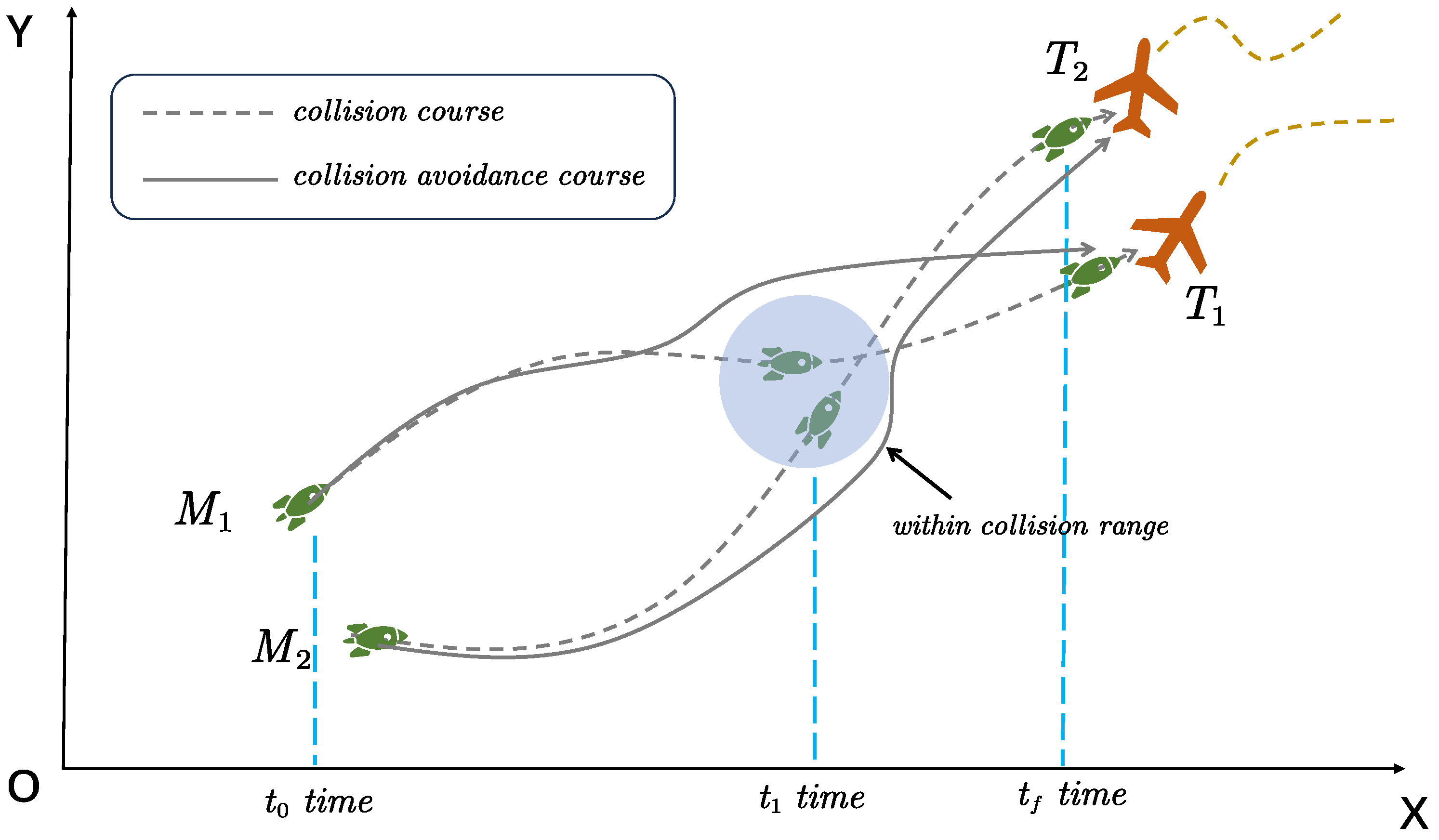
We present the flight scenarios and motion models and delve into the theoretical foundations underpinning this paper. Subsequently, we articulate the problem addressed in this paper. As illustrated in
Figure 2, when multiple UAV units track and engage targets, it is probable that the relative separation between UAVs falls below a safe threshold, posing a safety concern. The objective of this paper is to devise an appropriate cooperative guidance law
to ensure that the relative separation between UAVs during flight always exceeds the safe threshold, thereby achieving cooperative collision avoidance and ultimately intercepting targets.
3. Design of Collision-Avoidance Guidance Law
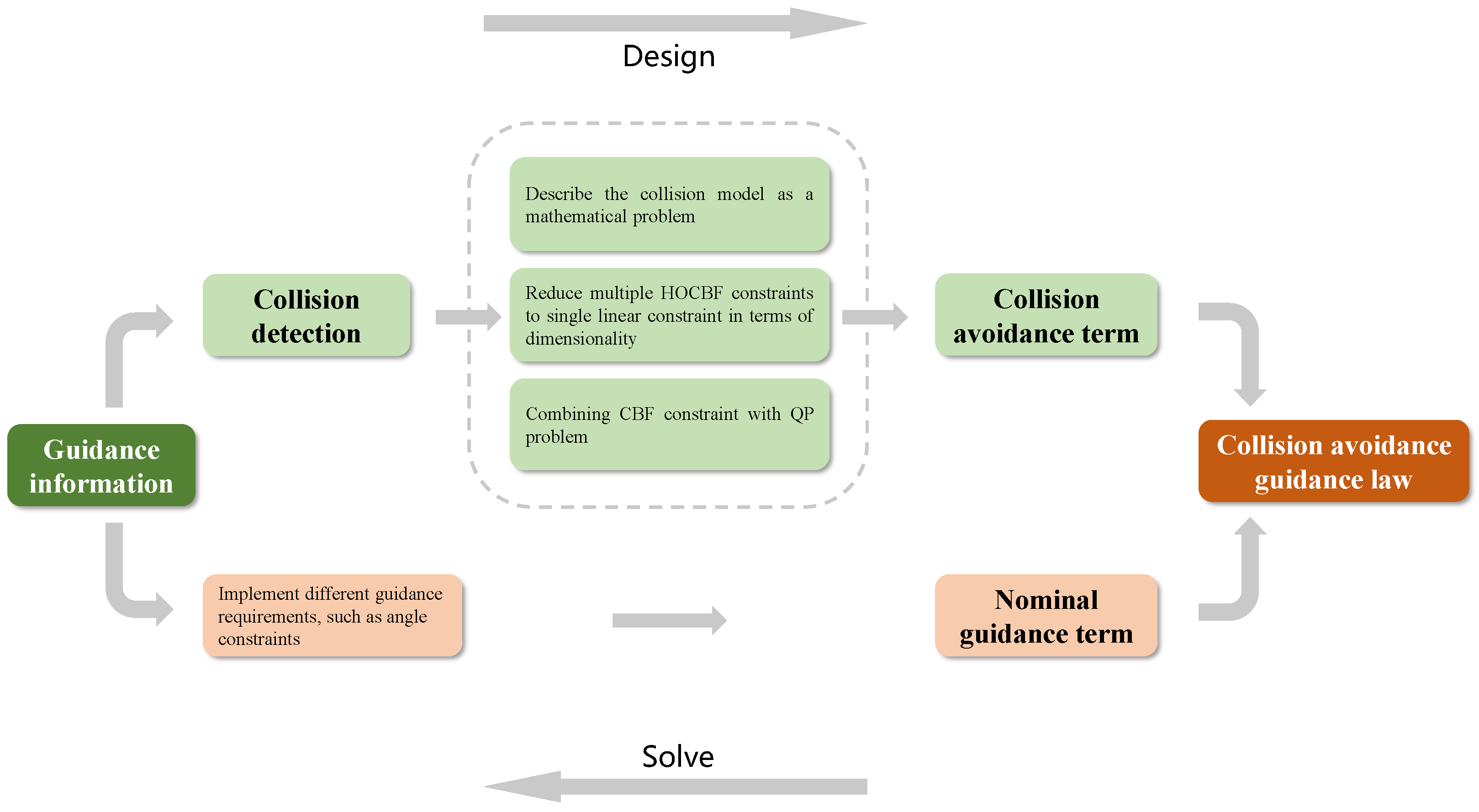
In this section, we delineate the primary techniques of the proposed collision-avoidance guidance strategy, as illustrated in
Figure 3.
Equation (
2) describes the relative motion between any two of the
n vehicles. Deriving the first equation in Equation (
2) with respect to time, we have Equation (
14):
where
,
and
denote the control inputs.
Defining system state vector as
, and substituting Equation (
14) into
, the state Equation (
15) can be obtained as
where, for the collision pair generated between
and
, we denote it by a two-dimensional tuple
, where
i <
j. Set
contains all the tuples, representing the set of all possible collision pairs.
Remark 2. In Equation (15), the presence of inputs and poses a challenging programming problem involving two variables when they are simultaneously added as control inputs to the constraints of the HOCBF. To address this issue, we treat as invariant when solving for , and subsequently utilize the derived value of to obtain a solution for . Along these lines, we acquire two nonlinear affine equations of state for
and
, respectively:
and
Let
be substituted by
and
by
; likewise, let
be replaced by
and
by
. Equations (
16) and (
17) are summarized into
and
Lemma 1 ([
27])
. Let be continuous for some domain . Suppose that exists and is continuous on . If, for a convex subset , there is a constant such that on , then for . Property 1. and turn out to satisfy the local Lipschitz condition for and .
Proof of Property 1. Taking the state derivation of
, we yield
Patently,
and
are continuous on
. For
, let r be small enough so that the neighborhood of
which is marked as
is contained in
. The set
is convex and compact. By contiguity,
is bounded on
. Let
be a bound for
on
. By Lemma 1,
is Lipschitz on
with Lipschitz constant
.
Considering is independent of , we believe that is continuously differentiable on . Hence, it is locally Lipschitz on . □
Property 2. and turn out to satisfy the local Lipschitz condition for and .
Proof of Property 2. Note that and have the same structure as and , respectively. Thus, and can be proved in the same method in Property 1. □
We choose CBF , where represents the minimum safe distance beyond which a collision between two LMs is recognized to be highly probable.
Property 3. The relative degree of is equal to 2.
Proof of Property 3. Taking the state derivative of along the vector , we obtain . In the following derivation, we obtain
, the same as for . □
According to Property 2, we build the second-order CBF constraints upon Equation (
12). After a sequence of derivations, we yield the intermediate equations of the second-order CBF with respect to
, taking
, that is:
Similar equations can be obtained with respect to
as
In guidance law designing, CBFs are often combined with quadratic programming (QP) issues to achieve safe control [
27], i.e.,
In this paper,
is required to monitor the flight status of the remaining UAVs in order to make informed decisions regarding its own flight path. The actions of the other
UAVs will impact
’s collision-avoidance maneuver, determining whether a potential collision may occur. Essentially, each additional vehicle imposes constraints on
. Thus,
can be expressed as follows:
where there exist
HOCBF constraints in total, obviously.
After a series of more tedious but easy to understand derivations, we can obtain the normal acceleration .
Theorem 1. Suppose Assumptions 1–4 hold. For system (18), with multiple linear HOCBF constraints described by CASE I (25), if the nominal guidance law used to intercept a target is denoted as , then there exists an analytic solution for the cooperative collision-avoidance guidance law as follows, that is: has different expressions under different conditions, described as follows: - 1.
If all ,where and the index y can be confirmed as , with . - 2.
If there exist and , satisfying
, we define the set as , in which all the elements are negative. K denotes the cardinality of . Similarly, we have in which all the elements are positive and L denotes the cardinality of . Let and ; we yield - 3.
If all ,,where the index y can be confirmed as .
Proof of Theorem 1. Now let us prove Theorem 1. Accordingly, the proof is divided into three parts, providing mathematical evidence for the formulas in each of the three scenarios stated in Theorem 1.
For the QP problem in Equation (
24), if all
, we yield
Of all the constraints in Equation (
30), we only need to ensure that
. Noticing that the cost function of Equation (
24) is a quadratic function, we compare
with
and yield
which is equivalent to
where
.
If there exist and , satisfying , denote including all the negative elements and including all the positive elements. K and L denote the cardinality of and .
Let
, so that
could satisfy all the constraints in Equation (
33). Similarly, let
, then
. Now the
constraints deduce to a closed interval constraint, that is
.
After the comparison of the interval endpoints
and
with
, it is found that
which equates to
If all
,
, we acquire
Then, we have
to satisfy all the constraints in Equation (
37).
Considering the similar situation in item 1 of Proof of Theorem 1, it is found that
which is tantamount to
□
Remark 3. It is important to note that an assumption is made that a solution always exists when solving for . This assumption defaults to a hidden condition in item 2 of Theorem 1, namely . Otherwise, the control input will have two contradictory ranges of values, , which ultimately leads to no solution. The implication of this mathematical problem in practical terms is that if needs to perform separate collision-avoidance maneuvers against other UAVs, there must be a connected region in the decision space for these maneuvers to ensure that avoids all other vehicles.
5. Simulations and Results
In this section, we will present the simulation results of various scenarios to analyze the performance of the guidance law proposed in this paper. Firstly, numerical simulations are conducted for the special scenarios mentioned in
Section 4, including two UAVs attacking two stationary targets and two uniformly moving targets. Furthermore, to demonstrate the applicability of the guidance law in multiple UAV scenarios, simulations with five UAVs attacking one stationary target and one uniformly moving target are also performed. Prior to engagement, target allocations are completed in advance. The proportional navigation guidance (PNG) law is used as the nominal input. Additionally, different parameters are adjusted in each set of scenarios to clearly represent the collision-avoidance effect of the simulation experiments. The proportional function is an excellent class
function utilized in our simulation experiments, with coefficients of 4 and 1 for
and
, respectively. In Equation (
6), the class
function is to smoothen the state trajectory as it approaches the boundary of the safe set, enabling UAVs with larger
to have more flexible maneuvers. In reality, the relative distribution of
and
is associated with measurement uncertainty and the accuracy of the UAV sensors, which, according to Assumption 4, need not be taken into account in this paper.
Table 1 and
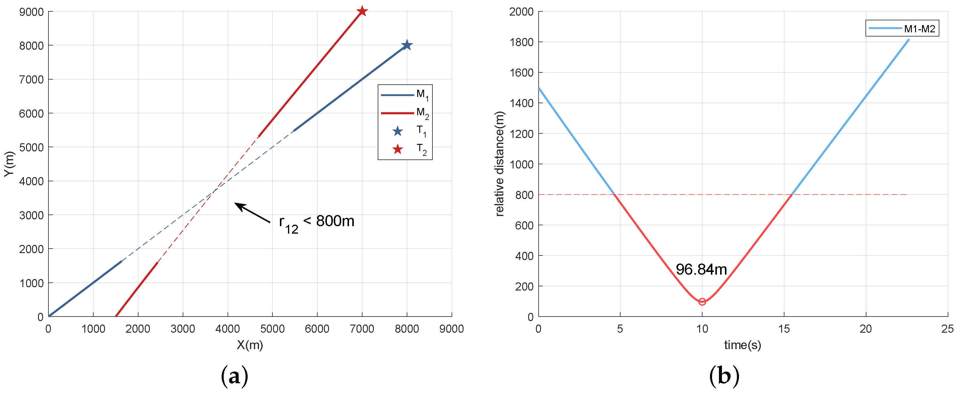
Table 2 present the initial parameters utilized for numerically simulating Scenarios 1 and 2, respectively. In Scenario 1, we model the deployment of two UAVs to individually target stationary objectives. In
Figure 4, it is evident that the minimum distance between
and
measures at 96.84 m, significantly below the designated safe threshold when employing PNG for target engagement by the UAVs, indicating a substantial risk of collision between them. The dashed lines indicate the trajectories of
and
whose relative distance is less than 800 m, which should be avoided.
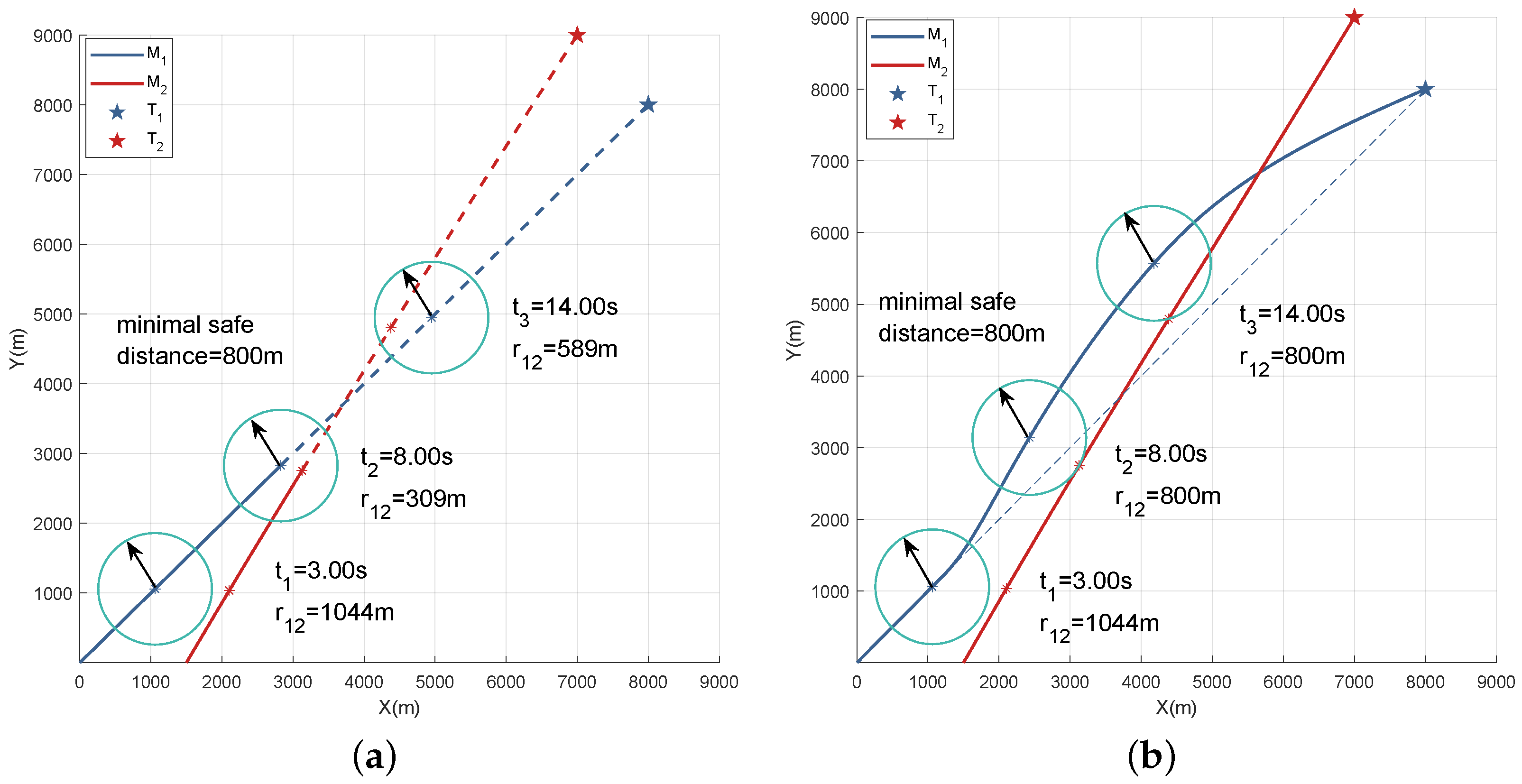
Figure 5 provides a more intuitive depiction of the collision-avoidance behavior of two UAVs under different guidance strategies in Scenario 1. We extracted the positions of the UAVs at three specific time points (3.00 s, 8.00 s, and 14.00 s). In
Figure 5a, at
3.00 s and 8.00 s, the relative distances between
and
are measured as 309 m and 589 m, respectively, both falling below the minimum safety distance threshold. In contrast, in
Figure 5b, the corresponding relative distances increase to 800 m.
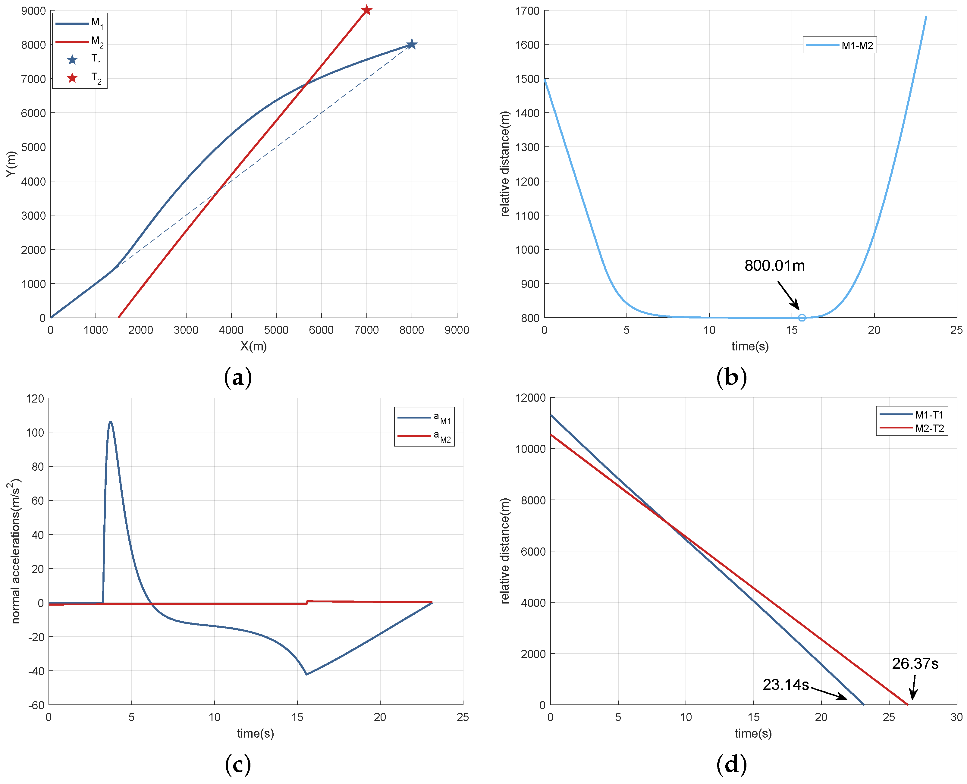
By implementing the guidance law proposed in this study, both UAVs are capable of maintaining a secure separation distance of 800 m, as shown in
Figure 6b. In
Figure 6a, the trajectories of UAVs in Scenario 1 are depicted. During the flight,
consistently follows a PNG trajectory, while collision-avoidance maneuvers are exclusively carried out by
. The dashed line in the figure depicts the PNG flight trajectory.
Figure 6c also demonstrates this outcome.
experiences nearly zero normal acceleration (the slight fluctuation shown in the figure is attributed to positive and negative changes in coefficients, which can be disregarded), whereas
performs collision-avoidance maneuvers upon detecting a collision, ceasing these actions once completed. This conclusion is supported by Equation (
26).
Figure 6d illustrates that the final relative distances of
−
and
−
are 0.39 m and 0.12 m, respectively, indicating that both UAVs successfully reached their targets at 23.14 s and 26.37 s with a miss distance of less than 1 m.
In Scenario 2, there are two objects moving uniformly along a straight line. Likewise, when
and
are guided proportionally to the target, their relative distance will be less than the minimum safe distance at a certain point in time, as depicted in
Figure 7a. Despite the fact that the minimum distance between the two amounts to 600.16 m (
Figure 7b), as per the settings in this paper, any distance less than the minimum safety distance is regarded as a collision. Similar to
Figure 5,
Figure 8 illustrates the temporal evolution of the relative positions of
and
. At 5.00 s, the separation between
and
increases from 698 m to 845 m, while at 9.00 s, it increases from 743 m to 801 m.
Upon the adoption of the collision-avoidance guidance law, the separation between
and
rises from 600.16 m to 800.01 m (
Figure 9b), guaranteeing safety during the flight. In
Figure 9a,c,
and
, respectively, execute the collision-avoidance guidance law at different intervals, thereby ensuring that the relative distance between them precisely meets the safety requirements. Furthermore, when the collision-avoidance guidance law is not in operation, they promptly switch back to PNG. Finally, they reach the targets at 26.53 s and 37.09 s, respectively, with a miss distance of less than 1m, as depicted in
Figure 9d.
Subsequently, we extend the model to include additional UAVs. A swarm of only two vehicles is insufficient for effective UAV operation. We increase the number of UAVs in our simulation experiment to verify whether the proposed guidance law can effectively prevent collisions as the number of vehicles grows. In Scenarios 3 and 4, we deploy five vehicles in each case to target a stationary object and a uniformly moving target, respectively. It is important to note that this article does not address simultaneous arrival, because the distances between UAVs approach zero as termination time nears, rendering collision avoidance impossible.
Table 3 and
Table 4 present the initial parameters for Scenarios 3 and 4.
In Scenario 3, as the UAVs follow the PNG course, ballistic overlaps occur within the confined battlefield space, resulting in multi-UAV separations of less than 800 m, as illustrated in
Figure 10. Conversely, when the UAVs adhere to the collision-avoidance guidance principle, safe separation distances are consistently maintained between UAVs and a distance of exactly 800 m is approached for a period of time, as depicted in
Figure 11b.
Figure 11a,c, respectively, depict the trajectories and normal accelerations of the five UAVs.
Figure 11d presents the distances between the UAVs and the targets, indicating that in this case a miss of distance can be achieved with an accuracy of less than 1 m.
The data presented in
Figure 12 indicate that the utilization of collision-avoidance maneuvers remains essential for ensuring the safe arrival of the UAVs at the target in Scenario 4.
Figure 13 depicts the trajectories and normal overloads of the UAVs in scenarios where the target is moving in a uniform straight line, with the dashed line in the trajectory diagram representing the PNG route. In Scenario 4, it is assumed that the target possesses high defense capability, rendering
−
unable to halt its progress after successive hits; however,
can effectively disable it upon impact. In
Figure 13a,
closely follows the PNG course, guiding other UAVs to execute reasonable collision-avoidance maneuvers based on this path. Consequently, there is minimal variation in
’s normal acceleration range, placing less demand on its maneuvering capabilities.
Figure 13d indicates that the miss distance of the five UAVs during target interception is less than 1 m.
6. Conclusions
Based on the CBF method, this paper constructed the QP problem of collision-avoidance guidance using the principle of relative distance collision avoidance, proved the mathematical theories covered in the article, and derived the closed-form solution of collision-avoidance guidance law with small computation amount and easy-to-obtain guidance parameters. And the proposed algorithm was numerically simulated and analyzed.
In the guidance law presented in this paper, once the initial parameters are provided, the flight trajectory and other simulation outcomes of the UAVs are determined, and the decision-making process is non-random. Consequently, we select the collision-avoidance effect (that is, the comparison between the relative separations between UAVs and the minimum safe distance) and the miss distance as the indicators to evaluate the performance of the guidance law. Based on our findings, this paper’s proposed guidance law demonstrated effective collision-avoidance capabilities across varying numbers of UAVs and targets in diverse motion states while exhibiting strong versatility. Additionally, it ensured precise maintenance of safe distances during collision-avoidance stages. By combining nominal and collision-avoidance elements within its structure, this versatile approach could be integrated with other guidance laws to prevent collisions and fulfill diverse navigation requirements. The reliance on relative distance for our collision-avoidance mechanism leads to significant acceleration changes as UAVs approach critical conditions—posing rigorous tests for their performance.
Future work will involve incorporating LOS angle-based CBFs into our control mechanisms to predict object motions more accurately, as well as developing space-time-constrained-aware collision-avoidance strategies inspired by this study. Additionally, we will also conduct research and perform Monte Carlo simulation regarding the large-scale collision-avoidance issue between swarms.

