Article

Near- and Far-Field Acoustic Characteristics and Sound Source Localization Performance of Low-Noise Propellers with Gapped Gurney Flap

1
Department of Mechanical Engineering, Tokyo University of Technology, 1404-1 Katakura-cho, Hachioji, Tokyo 192-0982, Japan
2
Department of Mechanical Engineering, School of Engineering, Tokyo Institute of Technology, 2-12-1 Ooka-yama, Meguro-ku, Tokyo 152-8552, Japan
3
Graduate School of Engineering, Chiba University, 1-33 Yayoi-cho, Inage-ku, Chiba 263-8522, Japan
*
Authors to whom correspondence should be addressed.
Drones 2024, 8(6), 265; https://doi.org/10.3390/drones8060265
Submission received: 15 April 2024 / Revised: 30 May 2024 / Accepted: 10 June 2024 / Published: 14 June 2024

Abstract

:
With the rapid industrialization utilizing multi-rotor drones in recent years, an increase in urban flights is expected in the near future. This may potentially result in noise pollution due to the operation of drones. This study investigates the near- and far-field acoustic characteristics of low-noise propellers inspired by Gurney flaps. In addition, we examine the impact of these low-noise propellers on the sound source localization performance of drones equipped with a microphone array, which are expected to be used for rescuing people in disasters. Results from in-flight noise measurements indicate significant noise reduction mainly in frequency bands above 1 kHz in both the near- and far-field. An improvement in the success rate of sound source localization with low-noise propellers was also observed. However, the influence of the position of the microphone array with respect to the propellers is more pronounced than that of propeller shape manipulation, suggesting the importance of considering the positional relationships. Computational fluid dynamics analysis of the flow field around the propellers suggests potential mechanisms for noise reduction in the developed low-noise propellers. The results obtained in this study hold potential for contributing to the development of integrated drones aimed at reducing noise and improving sound source localization performance.

1. Introduction

In recent years, multi-rotor drones have gained widespread use for various applications [1,2], with an anticipated surge in their presence in urban areas in the near future. Given this trend, there is a growing need to reduce the noise levels generated by drones. Drone noise is distinctive due to its flight operation at lower altitudes closer to human communities compared to conventional aircraft. It has been reported that drone noise has a higher pitch and a greater proportion of high-frequency broadband noise compared to general aircraft noise [3]. A study investigating the psychological impact of noise from various modes of transportation, including cars, aircraft, and drones, suggests that drone noise may be more harmful than noise from other vehicles [4]. This emphasizes the importance of mitigating drone noise, especially in urban environments. Recent efforts toward drone noise reduction include the evaluation of noise impacts from delivery drones in urban residential communities [5], the development of prediction tools to efficiently assess noise impacts in complex urban environments [6], and the proposal of modeling frameworks to set recommendations for drone operations minimizing noise impact on human communities [7]. These efforts reflect a commitment to addressing challenges specifically related to drone noise in urban settings, considering the concrete scenarios of urban environments.
The fundamental understanding of noise generated by rotating blades is provided by the formulation of the acoustic analogy in [8,9]. According to this theory, rotating blade noise consists of three fundamental components including thickness noise, loading noise, and flow noise. The relative contribution of each component to the total noise is determined by the flow velocity. For instance, in cases where the flow velocity is relatively slow, formulas that exclude the contribution of flow noise and are well suited for analyzing the sound emitted from moving surfaces, are commonly employed [10]. The drone investigated in this study operates at a Mach number of approximately 0.24, at the highest wing tip velocity. In this velocity range, where the contributions of load noise and flow noise are more significant than those of thickness noise, reducing the propeller rotational speed is expected to mitigate propeller noise. In our previous study [11], we successfully achieved noise reduction by increasing the blade area of the rotating blade, which led to a decrease in rotational speed under the hovering flight condition. Such passive silent designs for drone propellers that focus on the wing tip, leading edge, trailing edge, and blade profiles have garnered significant interest. For example, a study on wing tip shape introduced an innovative silent design with a loop-type wing tip achieved noise reduction while maintaining comparable flight performance to that with standard propellers [12,13]. However, another study suggests that, assuming the same propeller parameters such as diameter, thrust coefficient, and rotational speed, an increased number of blades can reduce blade tip noise more effectively than using a loop-type wing tip structure [14]. With regard to leading and trailing edges, numerous silent design approaches are inspired by the biomimetic structures of owls, renowned for their silent flight capability. A modified propeller with serrated structures based on owl feathers added to the leading edge was found to alter the laminar–turbulent transition on the suction surface of the propeller, suppressing velocity fluctuations around the propeller and achieving noise reduction in the high-frequency range [15]. Extensive research has been conducted on trailing edge serrations. A study investigating the effect of trailing edge serrations under the same thrust generation conditions as a baseline propeller demonstrated that the increased wing area led to decreased rotational speed and resulted in noise reduction across all frequency bands while improving aerodynamic performance [16]. Similarly, a model incorporating serrations by cutting the trailing edge, resulting in a reduced wing area, achieved noise reduction over a broad frequency range while maintaining aerodynamic performance equivalent to that of a baseline propeller during hovering flight [17]. A numerical study on the impact of trailing edge serrations revealed that serrated edges fragmented vortices, promoting rapid dissipation and reducing vortex intensity downstream of the propeller [18]. Recently, the passive boundary layer control using microfiber coatings on propeller surfaces has also been investigated. This approach achieved broadband noise reduction associated with vortex shedding interactions due to laminar boundary layer separation [19].
Gurney flaps, originally developed to enhance the downforce of racing cars, are one of the aerodynamic parts utilized in automotive applications. Typically, they consist of a short flat plate with a length of 1–2% of the wing chord length. To utilize this device as a high-lift device for fixed-wing aircraft, numerous studies have investigated its impact on aerodynamic performance by placing it on the pressure surface side of the trailing edge of airfoils. These studies have demonstrated that the appropriate selection of the length, thickness, attachment position, and attachment angle of the Gurney flap, taking into account the specific each airfoil shape and the Reynolds number, can enhance both the lift and the lift-to-drag ratio [20,21,22,23]. Although research on the application of the Gurney flap to rotor blades is less extensive than that on fixed-wing aircraft, several studies have been conducted. One such study is the investigation of the application of the Gurney flap to rotor blades in terms of the performance requirements of helicopter rotors. This study comprehensively investigated the aerodynamic characteristics of the Gurney flap through 2D analysis and proposed an optimal Gurney flap height that simultaneously minimizes drag and pitching moments while maximizing both the lift coefficient and the lift-to-drag ratio [24]. Other applications of Gurney flaps to rotary blades include the development of propellers for high altitude flight [25] and the silent design of axial flow fans [26]. However, to the best of our knowledge, few studies have applied Gurney flaps to the silent design of drone propellers considering three-dimensional flow structures.
In our previous study, we conducted research to apply Gurney flaps to drone propellers with the aim of achieving broadband noise reduction by reducing rotational speeds, tone noise reduction by reducing wing tip speeds [27,28], and high-frequency band noise reduction by interfering with vortices shed from the trailing edge. As a result, we developed a low-noise propeller inspired by Gurney flaps for drone applications [29]. One objective of this study is to comprehensively evaluate the effect of the developed low-noise propellers on noise characteristics. To this end, noise measurements were conducted in both acoustic near- and far-field environments during the flight of a drone equipped with the low-noise propellers. Additionally, we assessed their impact on sound source localization performance using a drone-embedded microphone array. As part of search and rescue operations for victims in disaster areas, search methods using drones have been researched for prompt search and rescue operations. Many of these methods are vision-based [30,31]. However, vision-based methods are difficult to search under poor lighting conditions or when victims are buried in rubble. Therefore, to search in such situations, search methods using auditory information such as voices obtained by a drone-embedded microphone array are being researched as “Drone Audition” [32]. In this technology, the sound sources are localized by processing the recorded sound alongside propeller noise. Confirming the effect of the proposed low-noise propellers on the performance of sound source localization is also one of the objectives of this research. Finally, by employing computational fluid dynamics methods, we aimed to gain a better understanding of the noise reduction mechanisms of the developed low-noise propellers, providing insights into the design guidelines for innovative propellers that excel in both noise suppression and sound source localization performance.

2. Materials and Methods

2.1. Drone and Propller

In the present study, the commercially available Inspire 2 propeller (1550T Quick Release Propeller, DJI Ltd., Shenzen, China) with a diameter of 15 inches and a propeller pitch of 5 inches was utilized as the standard propeller. Figure 1 illustrates the standard propeller alongside two Gurney flap-inspired low-noise propellers employed for the experiment and the numerical simulation. The imparting structures in the low-noise propellers are composed of cylindrical shapes with a diameter of 1 mm and a height of 3 mm (named 3 mm_GF) or 8 mm (named 8 mm_GF) and were fabricated by a 3D printer (Ultimaker S3, Ultimaker Ltd., Geldermalsen, The Netherlands) using ABS resin. Note that these imparting structures did not cause any deformation under the operating conditions in the present study. Sixteen of these structures were arranged at the trailing edge with equal intervals of 1 mm, starting from a position 30 mm away from the blade tip towards the blade root, as depicted in Figure 1a. Comparative studies on the noise and flight performance of these structures in contrast to the conventional Gurney flap structure (rectangular plates without gaps), and various arrangement effects, such as the height of the cylinder and the spanwise location including the design procedure, for the selected configurations in the present study can be found in our previous study [29]. Table 1 presents a summary of the measured parameters under hovering flight conditions with the standard propeller. Note that “Wing length” refers to half of the propeller diameter in the present study.

2.2. Simultaneous Measurement of Force and Noise of a Single Propeller and Far-Field Noise Measurement In-Flight

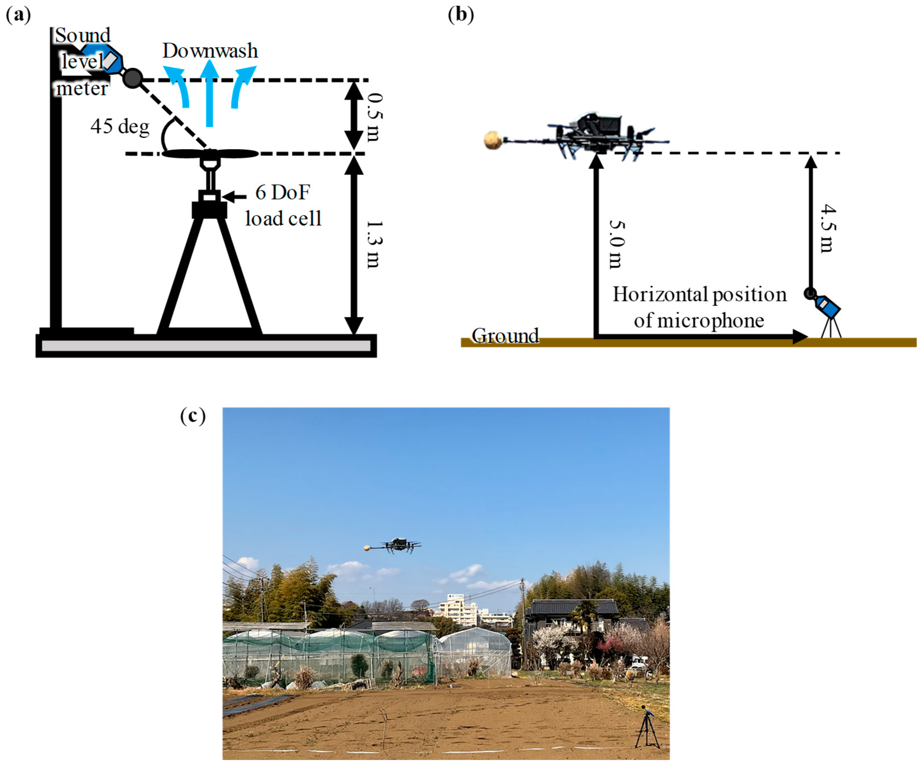
A schematic diagram of the simultaneous force and noise measurement system for a single propeller is shown in Figure 2a. A single propeller and a brushless DC motor (DR55-M, Shinano Kenshi Co., Ltd., Nagano, Japan) were affixed to a 6-Degree-of-Freedom (DoF) load cell (CFS034CA101U, Leptrino Inc., Nagano, Japan). A sufficiently large, quiet room (18 m × 9 m × 8.4 m) located at the Center for Aerial Intelligent Vehicles (CAIV) of Chiba University was utilized for the measurement of the force and noise of the single propellers. Due to the horizontal distances between the blade tips and the building walls being at least 20 times greater than the wing length, the wall effects due to flow interactions are anticipated to be minor under this circumstance. The steady forces investigated in the present study were derived by capturing the time-varying dynamic forces at a frequency of 600 Hz acting on the propeller models over a 60 s period and averaging the results. The rotational speed of each model was adjusted under the condition of constant lift considering hovering conditions for Inspire 2.
For noise assessment, a high-precision sound level meter (NL-52, RION Co., Ltd., Tokyo, Japan) with a sensitivity of −27 dB was placed both vertically and horizontally from the center of the propeller hub at a fixed distance of 0.5 m. Noise measurements were conducted simultaneously with force measurements and extended over a duration of 60 s. In a calm indoor environment, sound pressure levels (SPLs) of all the data were calculated as follows:
O A S P L = 20 log 10 1 N i = 1 N P A 2 ( i ) 0.5 / P 0 ,
where PA is the instantaneous A-weighted sound pressure with the measuring frequency band ranging from 20 Hz to 20 kHz. P0 expresses the reference sound pressure, and it is equal to 20 µPa. N is the number of samplings, and the sampling frequency is 48 kHz. It should be noted that in the indoor environment without rotor noise, the overall SPL is approximately 30 dBA.
In-flight experiments for noise measurements were conducted on an agricultural field in Hachioji, Tokyo (Figure 2c). The drone equipped with a front-mounted microphone array was used to simultaneously evaluate the sound source localization performance. With this drone in hovering flight at a height of 5 m, measurements were conducted at three horizontal microphone positions at 3, 4.5, and 6 m (Figure 2b). In this noise measurement setup, the distance between the propeller blade tip and the microphone located at the closest horizontal position of 3 m is approximately 13 times the diameter of the propeller. It has been reported that in noise measurements of a single propeller with a diameter of 240 mm, the acoustic far-field conditions are satisfied when the microphone is placed more than 1 m away from the center of the propeller [33]. Therefore, in the present study, we define this noise measurement as the “far-field” condition.

2.3. Near-Field Noise Measurement Using Sperical Microphone Array and Sound Source Localization In-Flight

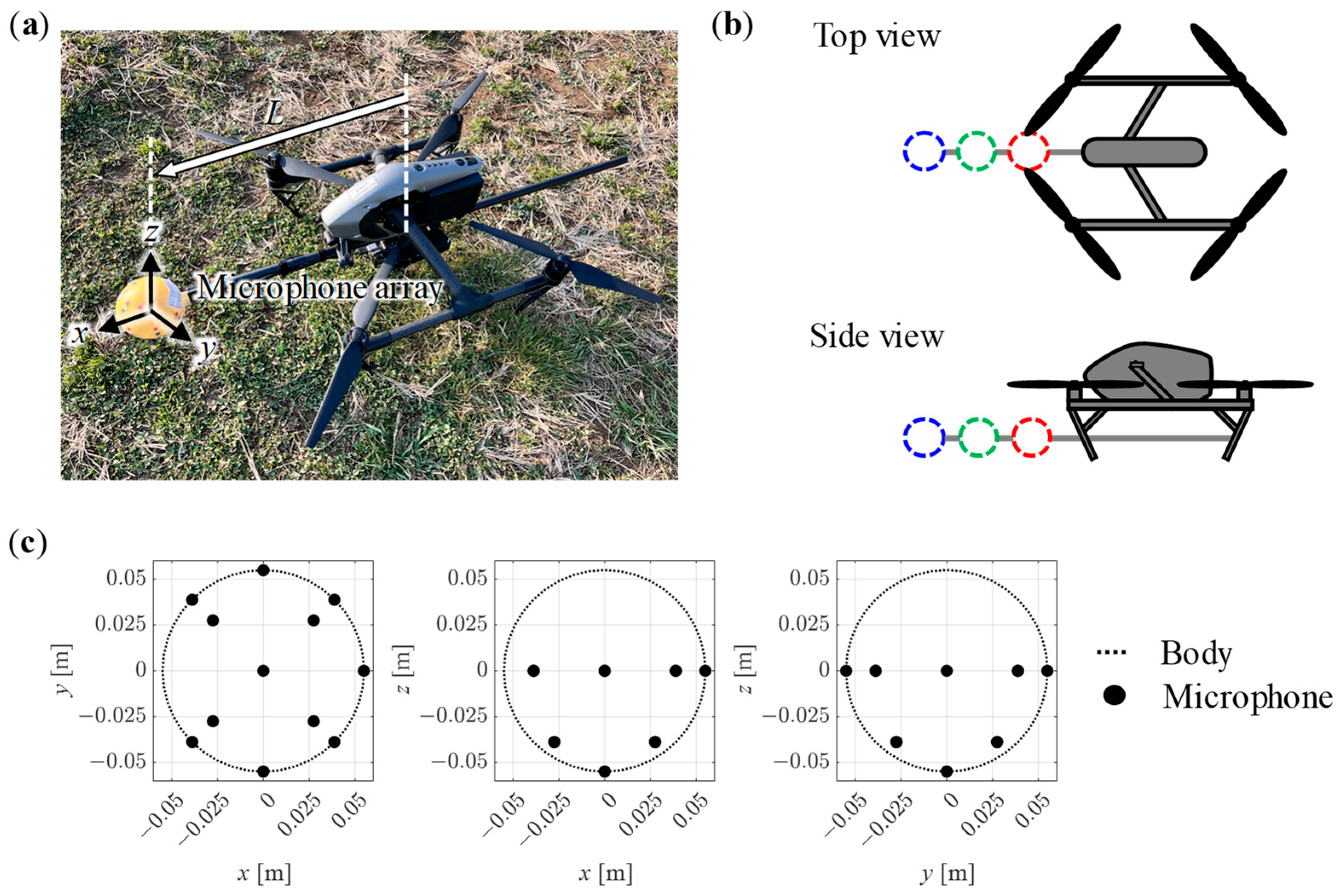
As shown in Figure 2c, noise was also recorded using the microphone array embedded on the drone to evaluate the performance of sound source localization. Figure 3a shows the drone equipped with the microphone array. The drone and the microphone array were connected by a single pipe. The distances between the center of the drone and the microphone array, L, were varied by 600, 450, and 300 mm (Figure 3b), and the sound source localization performance and noise at these three positions were evaluated. In this noise measurement setup, the distance between the propeller blade tip and the microphone array located at the farthest position, L = 600 mm, is approximately 0.73 times the diameter of the propeller. Therefore, in the present study, we define this noise measurement as the “near-field” condition based on the previous study [33]. It should be noted that noise measurements were conducted by using the lower hemisphere of the spherical microphone array to evaluate the potential impact of propeller noise on the sound source localization performance. The microphone array consists of 12 MEMS microphones arranged in a spherical body with a diameter of 110 mm. The position of each microphone is shown in Figure 3c. Using this microphone array, noise was recorded at a sampling frequency of 16 kHz and a quantization bit rate of 24 bits while the drone was hovering. To eliminate the influence of natural wind, the experiment was performed only in windless conditions. The evaluation signals were created by adding the recorded noise and the target sounds arriving from various directions generated by numerical simulation, and the performance is evaluated by processing the sound source localization. As target sound samples, voice and whistle sounds were used.
For sound source localization, methods based on MUSIC (multiple signal classification) [34], which is a kind of subspace method, SEVD-MUSIC (MUSIC based on Standard EigenValue Decomposition), iGEVD-MUSIC (MUSIC based on incremental Generalized EigenValue Decomposition) [35], and AFRF-MUSIC (MUSIC with Active Frequency Range Filtering) [36] were used. SEVD-MUSIC is the original MUSIC that estimates the direction of arrival (DOA) of a signal from the arrival time difference of the signals recorded by each microphone. SEVD-MUSIC has no noise suppression calculations, so it has a low noise tolerance. iGEVD-MUSIC models noise by assuming the recorded sound a few seconds before the current time to be noise and whitens the noise by generalized eigenvalue decomposition. AFRF-MUSIC dynamically creates a frequency filter using the assumed noise to eliminate the effect of noise. The evaluation signals with different signal-to-noise ratios (SNRs) were created, sound source localization was performed with each method, and the success rate was calculated. The spatial resolution of MUSIC was 5 deg. in both azimuth and elevation angle, and the temporal resolution was 0.5 s.

2.4. Flow Field Analysis around Propeller

A comprehensive examination utilizing a computational fluid dynamics (CFD) model was conducted to assess the aerodynamic and aeroacoustic properties of the propeller models. This simulation-based investigation was performed using the commercial software ANSYS CFX 2022 R2 (ANSYS Inc., Canonsburg, PA, USA). Considering the flow field characteristics in the Reynolds number regime, a Reynolds Averaged Navier-Stokes (RANS) model of turbulent flow with SST (Shear Stress Transport) turbulence modeling was adopted. For incompressible and steady flows, the governing equation is as follows:
u j x j = 0 ,
u j u i x j = 1 ρ p x i + μ ρ 2 u i x j x j x j ( u i u j ¯ ) ,
where i and j denote suffixes for tensor notation, ui and xi denote the velocity and position vectors, and ρ, p and μ denote the fluid density, the pressure, and the dynamic viscosity, respectively. The blending strategy using the k-ω and k-ε models is the SST model proposed in the previous work [37]. The k-ω model was employed at the surface, whereas the k-ε model can be used for the boundary layer’s edge and its surrounding region. The governing equations are discretized using the finite volume method, and a blending scheme between the first-order upwind differencing scheme and the second-order central differencing scheme, known as the high-resolution scheme in this software, was used to solve the advection terms in both equations.
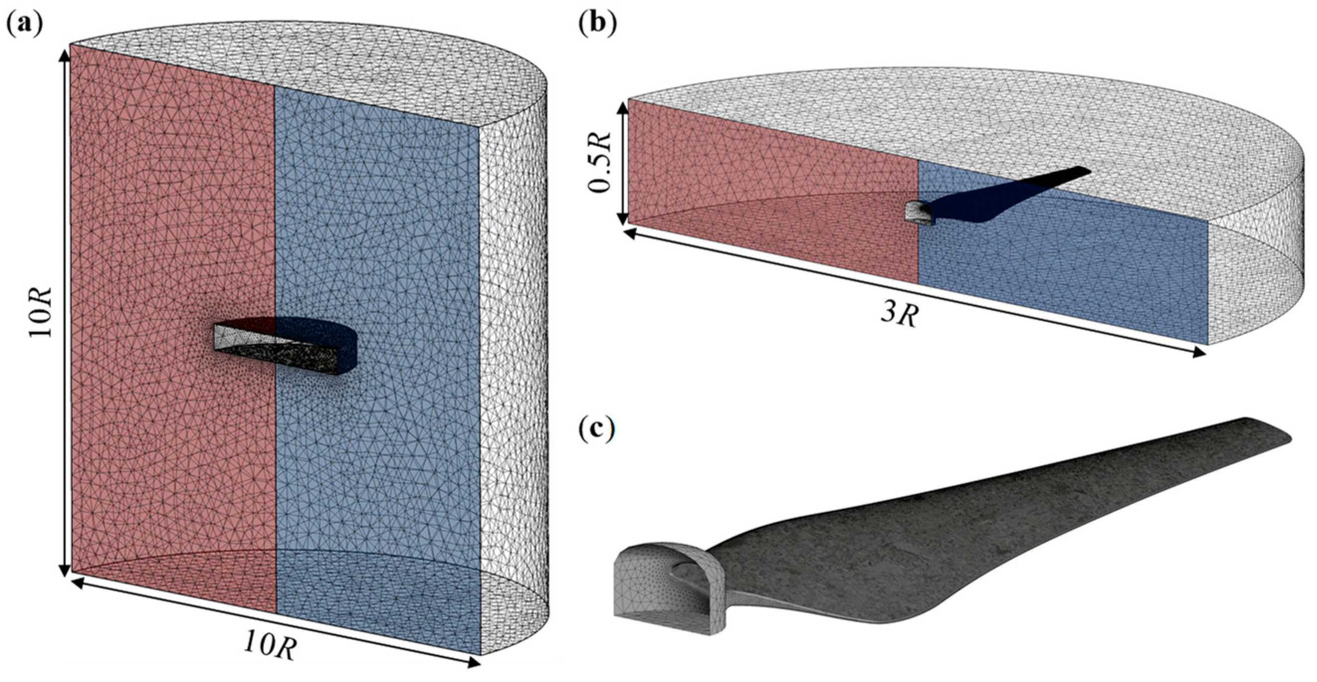
A multi-blocked hybrid grid system with static (Figure 4a) and rotating (Figure 4b) domains was used to accurately resolve the turbulent flow and the flow separation around the propeller surfaces (Figure 4c). To reduce computational costs, a periodic boundary condition was applied at the inlet (colored in red) and at the outlet (colored in blue). These conditions were implemented in both the static and rotating regions. A Frozen Rotor model was used at the boundary faces between the rotating and static domains. The propeller’s surface was set to be the no-slip wall boundary conditions, and 15 prism layers were imposed on the surface, with the first layer having a height of 0.012 mm and a growth rate of 1.04. The static domain’s other boundary planes were set to the opening boundary condition with 0 Pa relative pressure. The operating conditions of the tested propellers are summarized in Table 2. A sensitivity analysis on grid points was performed in our previous study [29]. Note that each model’s rotating speed was set to the value acquired during the experiment of the single propeller at constant lift considering hovering conditions for Inspire 2.

3. Results and Discussion

3.1. Effects of Gurney Flap-Inspired Structures for Drone Propellers on Flight Efficiency and Noise

Here we briefly present the performance of the Gurney flap-inspired propellers obtained from the single propeller experiment in our previous study [29]. The figure of merit (FM) for a propeller is defined to evaluate flight efficiency in hovering flight conditions. The formulation is as follows:
F M = P R F P r e a l ,
where Preal expresses the actual power given by the product of the measured torque about the rotational axis and the angular velocity. PRF is the ideal power, that is, the minimum power for generating the resultant lift force, L, which was obtained from the experiment, and can be derived by using the Rankine–Froude momentum theory as follows:
P R F = L 3 / 2 2 ρ A ,
where ρ is the density of air and A is the area of the actuator disk [38].
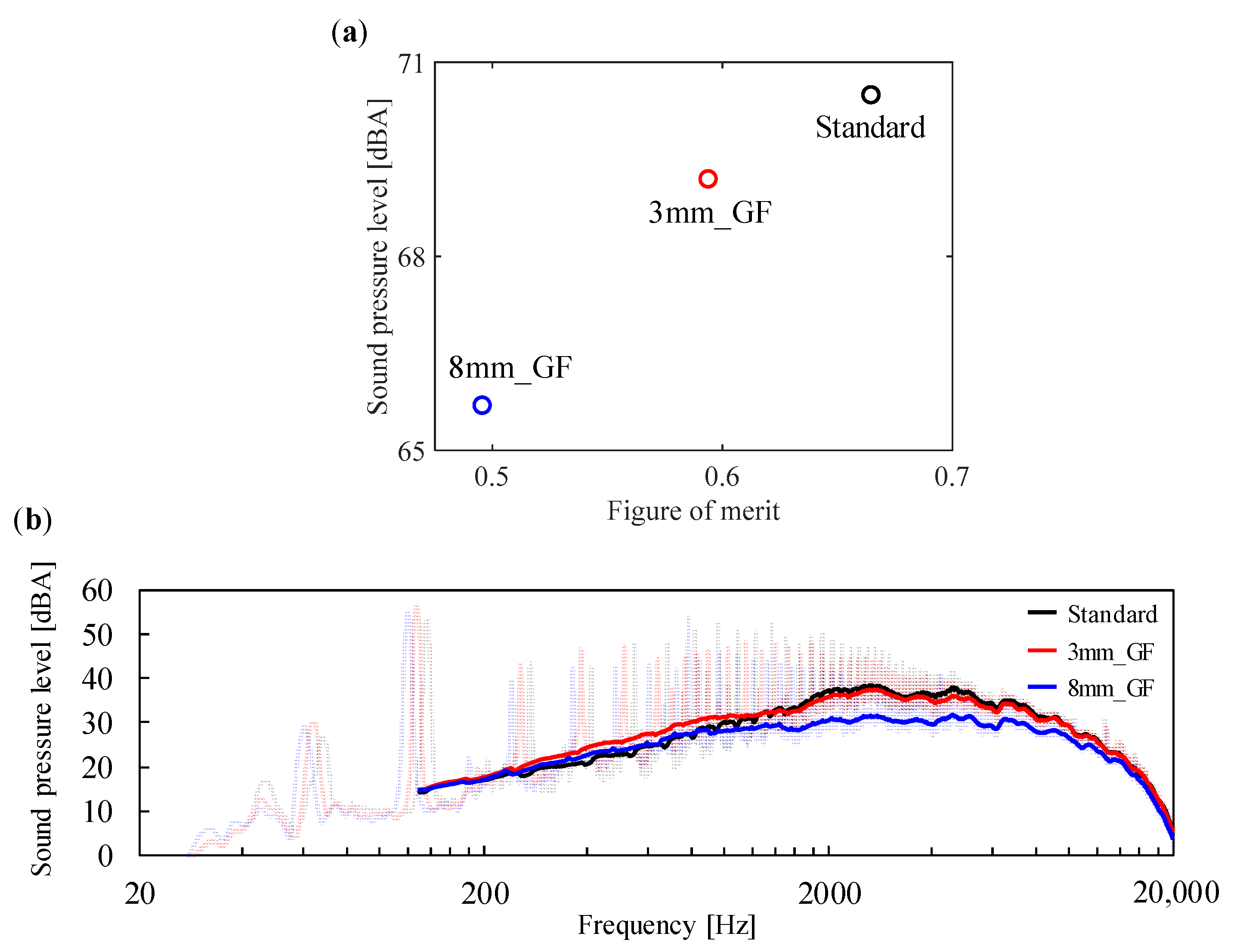
The effects of the Gurney flap-inspired structures on the SPL and FM are summarized in Figure 5a. The experimental results show that the standard propeller produces the necessary lift force for hovering flight at a rotational speed of 4100 rpm with the FM of about 0.66. Note that the blade passing frequency is twice the rotational frequency, which is 136.6 Hz, due to the two-blade propeller type. The SPL at this rotational speed was measured to be 70.5 dBA, indicating a high noise level. The introduction of the Gurney flap-inspired structures results in noise suppression but comes at the cost of reduced efficiency compared to the standard propeller. Compared to the standard propeller, the efficiency is reduced by 10.6% and 25.4% for the 3 mm_GF and 8 mm_GF models, respectively. At the same time, the noise level is suppressed by 1.3 dBA and 4.8 dBA, respectively. This trade-off between efficiency and noise reduction highlights the impact of Gurney flap structures on the performance characteristics of the propeller. The spectral analysis of the measured noise (Figure 5b), performed with a resolution of 2.5 Hz, shows that the Gurney flap-inspired structures lead to reductions in the rotational speeds, from 137.5 Hz to 127.5 Hz in the 3 mm_GF model (colored in red) and 125.0 Hz in the 8 mm_GF model (colored in blue) compared to those of the standard ones. Furthermore, a notable feature of this structure with gaps, which differs from the conventional Gurney flap (plate-like structure without gaps), lies in its ability to suppress the increase in the SPL at a given frequency associated with the separation of vortices generated by the edge of the plate-like structure. For example, in simultaneous measurements of time-resolved particle image velocimetry and acoustic characteristics of the airfoil with a NACA0015 profile equipped with a conventional gapless plate-type Gurney flap placed in a uniform-flow, a high sound pressure level was reported at the vortex shedding frequency from the edge of the Gurney flap [39]. Even in the case of rotary blades, similar results were observed in our previous study [29]. The adopted structures with gaps effectively mitigate the increase in noise levels at specific frequency bands caused by conventional gapless plate-type Gurney flaps, achieving noise attenuation especially in the range of 2 to 10 kHz.

3.2. Noise Characteristics in the Far-Field In-Flight

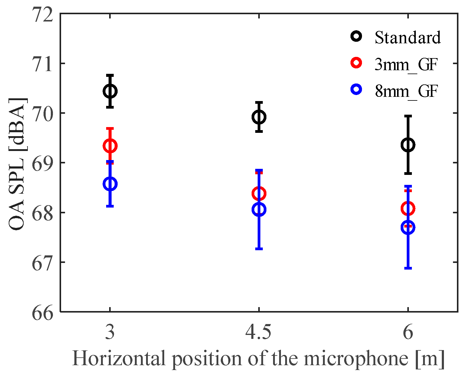
In the in-flight experiment of the hovering drone, noise measurements were conducted for 10 s at each horizontal position (see Figure 2b), repeated five times. Figure 6 illustrates the overall SPLs and the standard deviations at each position represented with error bars. Regarding the effect of the horizontal microphone positions, the highest noise level was observed at a horizontal position of 3 m, measuring about 70.5 dBA with the standard propeller. The noise levels at horizontal positions of 4.5 and 6 m attenuated almost linearly, reaching approximately 69.4 dBA at the farthest position for the standard propeller. In a previous study [40], noise measurements were conducted outdoors at an altitude of 5 m, similar to our experiment. The results showed a noise reduction of 2.5 dBA by increasing the horizontal distance of the microphone from approximately 2.9 m to 5 m from the center of a drone. Compared to this result, our experiment revealed that the noise attenuation effect due to changes in the horizontal position of the microphone was smaller. This is likely due to the difference in aircraft size used in this experiment compared to the one in the literature (less than half the size in terms of propeller diameter), and as described below, during hovering flight with the drone equipped with the microphone array, the rotational speed of the propellers on the side with the microphone array increased to stabilize the attitude of the drone, causing the four propellers to not rotate at the same rotational speed. The acoustic radiation of a drone is assumed to be angle-independent on the horizontal rotor plane, but there is directionality in the vertical direction [41,42]. This directionality has been clearly demonstrated in outdoor measurements similar to this study, under distance correction based on the assumption of spherical wave propagation [40]. In this experiment, the noise measurements are performed by fixing the altitude of the drone and varying the horizontal position of the microphone. Thus, the experiment includes the effects of both distance and the directionality in the angle of elevation between the drone and the microphone. It should be noted that the directivity of the acoustic radiation may differ from that of a typical drone due to the different rotational speeds of the propellers on the forward and aft sides of the drone equipped with the microphone array. Regarding the effect of the imparting structures, the 8 mm_GF model achieved the most significant noise reduction at the 3 m horizontal position, reaching approximately 68.6 dBA. Furthermore, the 3 mm_GF and 8 mm_GF models showed the most significant differences at this position, achieving noise reductions of 1.1dBA and 1.9dBA, respectively, compared to the standard propeller. In other horizontal positions, both the 3 mm_GF and 8 mm_GF models achieved noise reductions of more than 1 dBA over the standard propeller at all positions, but no significant difference was observed between these two models at the 4.5 and 6 m horizontal positions.
The averaged results of the spectral analysis of the measured noise at each horizontal position are illustrated in Figure 7. In the blade passing frequency (BPF) range from 125 to 162.5 Hz, a reduction in rotational speed is observed with the Gurney flap-inspired structure models (red and blue lines) in all horizontal microphone positions, in a manner similar to the experimental results of the single propellers (see Figure 5b). In addition, due to the microphone array being mounted at the front of the drone, the rotational speed of the propeller is higher on the front side compared to the rear side when stabilizing the attitude. This results in a double-peak waveform in the BPF range. In terms of directivity, the greatest noise comes from the propeller surface [43]. In this experiment as well, the sound pressure level is dominated by the tonal noise of the BPF, which gradually increases up to the fourth harmonic of the BPF and then remains at a high level up to about 2 kHz. Noise above 2 kHz is classified as high-frequency broadband noise induced by turbulence, wing tip vortices, trailing-edge vortices, and other vortices generated by the propeller [27]. In this frequency range, the SPL gradually decreases.
To better assess the differences in the sound levels, the SPL for the tested propellers was calculated in one-third octave bands, and the difference from the standard propeller, ΔSPL, was calculated (Figure 8). The choice of one-third octave bands was made to facilitate the identification of higher energy frequency bands compared to narrow band analyses as reported in [4,42,44]. Up to a frequency band centered at 630 Hz (approximately the fourth harmonic of the BPF), the SPLs fluctuate due to the differences in the BPFs of the standard and Gurney flap-inspired propellers. Beyond the frequency band centered around 800 Hz, the Gurney flap-inspired models consistently achieve a reduction in SPL over the entire frequency band up to 10 kHz. The difference in SPL between the 3 mm_GF and 8 mm_GF models is particularly evident at the horizontal microphone position of 3 m. The discomfort experienced by humans induced by drone noise can be attributed to specific acoustic characteristics that are unique to drones, such as pure tones and high-frequency broadband noise [4]. In addition, a key difference between drones and civil aircraft is the significantly higher energy of high-frequency sounds (above 3 kHz) for drones due to their lower flight altitude [3]. The Gurney flap-inspired propellers used in this study have achieved noise reduction in this high frequency range. The noise reduction effect in the high-frequency broadband range is expected to contribute to improvements in the usability of drones in urban environments.

3.3. Noise Characteristics in the Near-Field and Sound Source Localization Performance In-Flight

Figure 9 illustrates the frequency spectrum of the noise recorded by the microphone array mounted on the drone. Note that these results were obtained using 12 points of the lower hemisphere of the spherical microphone array (see Figure 3), recorded over 45 s, to evaluate the potential impact of propeller noise on the sound source localization performance of the microphone array. The horizontal axis represents frequency, and the vertical axis represents sound power. The microphone array used in the experiment cannot obtain absolute sound pressure. Then, the relative value to the maximum value of the frequency spectrum of the standard propeller at L = 600 mm (black line in Figure 9a) was calculated as the sound power. As an overall characteristic, the sound power increases as L decreases. In terms of partial characteristics, a high-power component was observed at frequencies lower than 1 kHz, with minimal differences observed due to the propeller types, while the difference between the standard and Gurney flap-inspired models increased with decreasing L for components at frequencies higher than 1 kHz. Thus, compared to the results observed in the acoustic far-field as shown in Figure 8, noise with the same characteristics was also observed in the acoustic near-field.
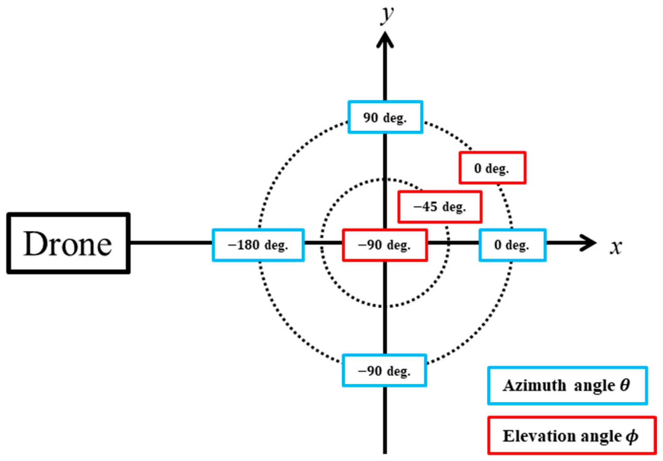
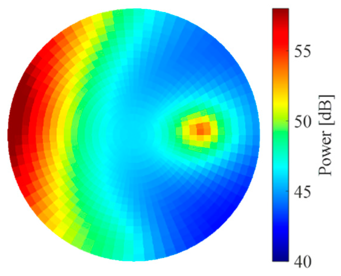
The spatial spectra calculated by each sound source localization method are shown below. The spatial spectrum represents the sound power arriving from each direction. In addition to information about the target sound, the spatial spectrum provides information about how the propeller noise reaches the microphone array and how it affects sound source localization performance. In this paper, a spatial spectrum is plotted with the axes given in Figure 10. The circumferential and radial directions represent the azimuth angle θ and elevation angle ϕ, and the sound power is represented by a color map. It should be noted that the sound source localization performance is evaluated under the assumption that the explored sound sources are located below the drone. Therefore, the elevation angle ϕ is evaluated on the underside of the spherical microphone array.
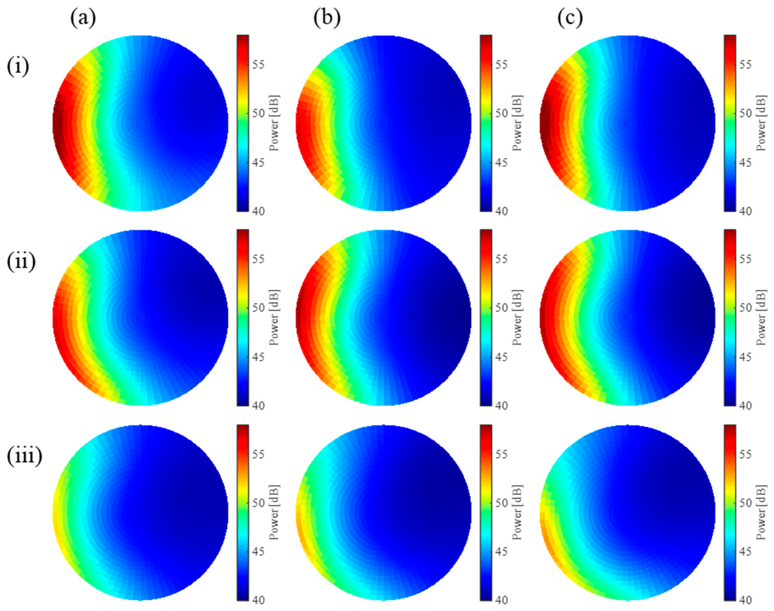
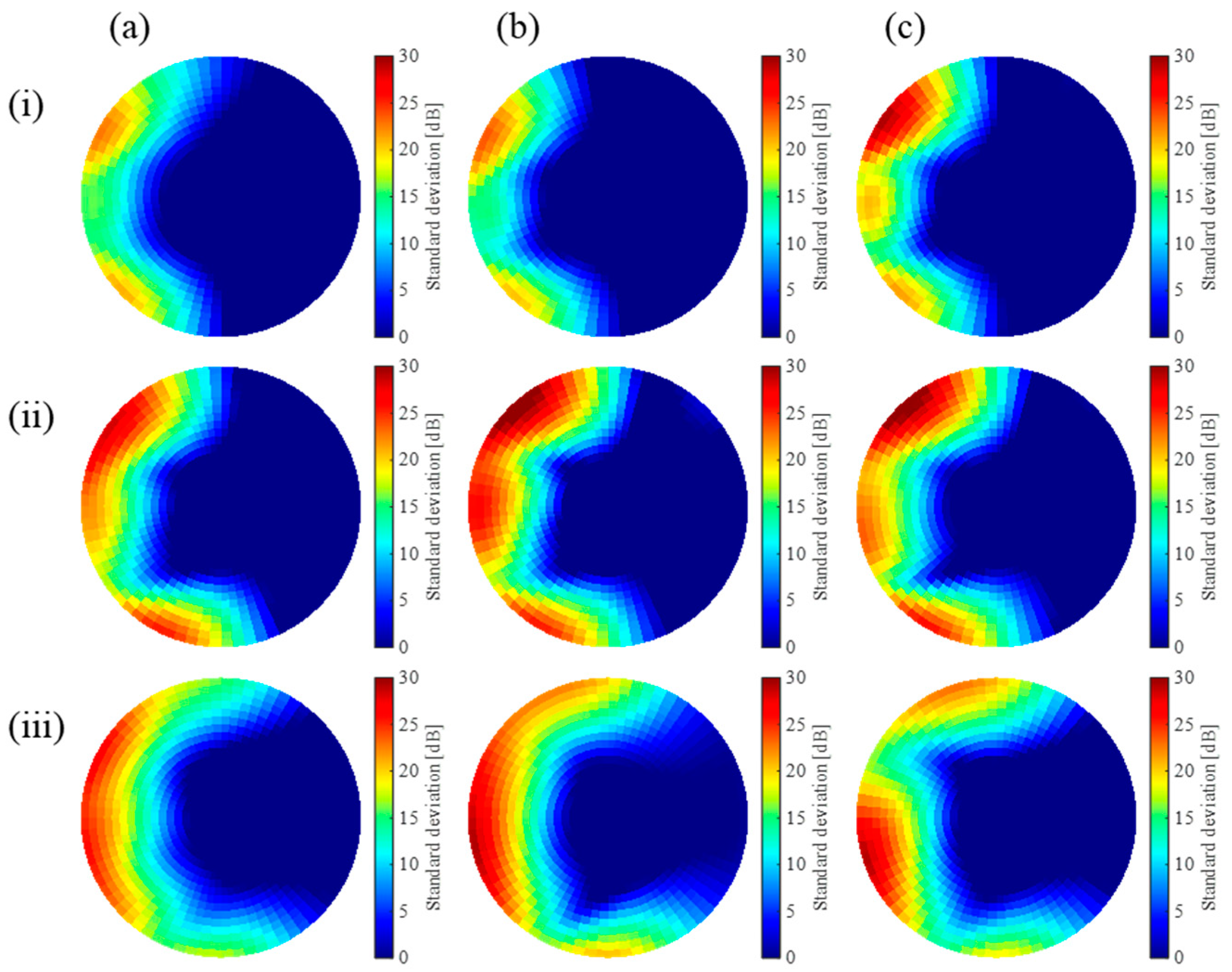
Figure 11 depicts the averaged spatial spectra of the recorded noise over 45 s calculated by SEVD-MUSIC. Panels (a)–(c) correspond to the results for the standard, 3 mm_GF, and 8 mm_GF, respectively. In addition, panels (i)–(iii) correspond to L = 600, 450, and 300 mm, respectively. The high values on the left side mainly represent the components of noise generated from the propeller. In addition, the time variation is also calculated. In the previous report, we evaluated the power and directional range of the noise at a given moment [45]; however, time variation is an important factor for some sound source localization methods. Figure 12 shows the standard deviations of the spatial spectra at a given θ and ϕ, PSD, calculated as follows.
P S D θ , ϕ = s t d P θ , ϕ , t a l l   t
Here, t is the time, and P is the spatial spectrum. PSD serves as an index of the time variation in the spatial spectrum over 45 s. Similar to Figure 11, Figure 12 is plotted with the axes referenced in Figure 10, and the standard deviation in each direction is represented by a color map. The averaged spatial spectra show that the power and directional range of the noise decreases as L decreases. This is because the direction of arrival of the noise moves in the positive direction of the elevation angle as L decreases due to the positional relationship between the propellers and the microphone array. At L = 300 mm, the arrival direction of the noise with the highest power is above ϕ = 0 deg. Then, the power and directional range of noise become smaller in the plotted range below ϕ = 0 deg. Comparing with different propellers, there is almost no difference in the directional range of the noise. It was found that the 3 mm_GF model had the lowest noise power at L = 600 mm, and the standard model had the lowest noise power at L = 300 mm. On the other hand, the standard deviations at L = 600 mm show that the 8 mm_GF model had the largest standard deviation, i.e., the largest time variation, and there is almost no difference in the directional range of the time variation among the different propellers. Even at L = 300 mm, the 8 mm_GF model had the largest time variation; however, it had the smallest directional range of time variation. In summary, compared to the standard and 3 mm_GF models, it has a lower noise power when L is large, and on the contrary, it becomes higher when L is small. The 8 mm_GF model has no advantage in noise power; however, it has a smaller directional range of time variation when L is small. These are thought to be due to the complexity of the airflow caused by the Gurney flap-inspired models, which also complicates the sound propagation.
Finally, the performance of sound source localization is evaluated. As described in Section 2.3, the evaluation signals are created by adding the target sound to the recorded noise and processed by each sound source localization method. Figure 13 shows an example of the spatial spectrum of the evaluation signal. In this figure, the target sound direction is set to θ and ϕ = 0 deg. and −45 deg., respectively. Sound source localization is performed for such a spatial spectrum. Localization success is defined when the error between the localized target sound direction and the set value is within 10 degrees. The target sound direction was set in 5 deg. increments within the range of −180 to 180 deg. for θ and −90 to 0 deg. for ϕ. For each propeller and L, the success rate was calculated using a total of 583,650 evaluation signals, including 90 frames (=45 s), 1297 target sound directions, and five SNRs.
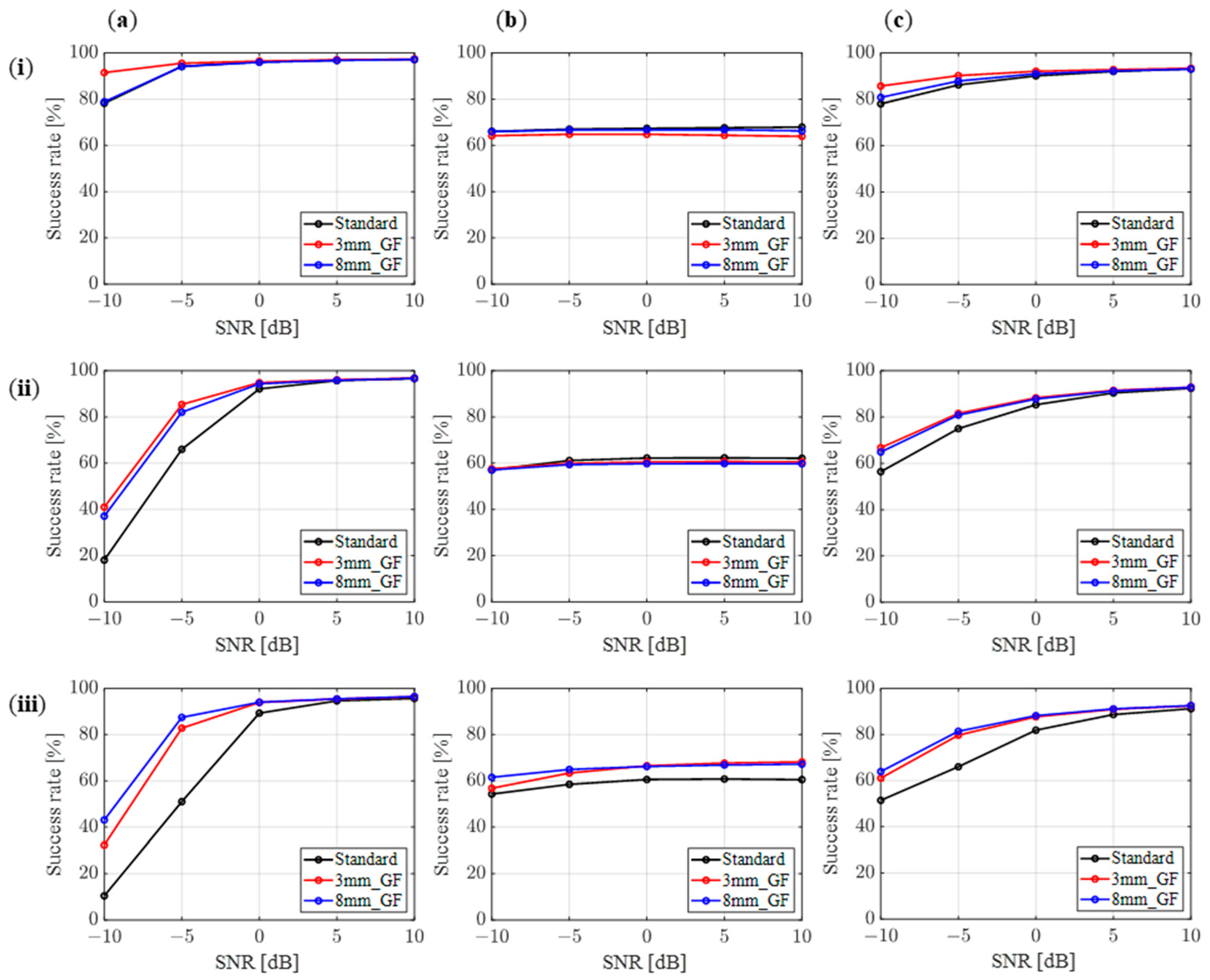
Figure 14 shows the calculated success rate. Panels (a)–(c) represent the results of SEVD-MUSIC, iGEVD-MUSIC, and AFRF-MUSIC, and panels (i)–(iii) show the results for L = 600, 450, and 300 mm, respectively. The horizontal axis represents the SNR, and the vertical axis represents the success rate. In SEVD-MUSIC, the noise power at a given moment affects the success rate of localization. The noise power has been discussed in terms of the averaged value in Figure 11. However, due to the time variation as shown in Figure 12, the noise power at a given moment is expected to have different characteristics from Figure 11. As a result, although there was a small difference between each propeller, the 3 mm_GF model had the highest success rate when L was large, as shown in Figure 14a(i). As L decreased, the success rate of the Gurney flap-inspired models became dominant, and the 8 mm_GF model had the highest success rate at L = 300 mm as shown in Figure 14a(iii). In iGEVD-MUSIC, if there is a time variation in the power and directional range of the noise, the noise cannot be correctly whitened and the localization performance will decline. In this experiment, the success rate is approximately 60% due to the time variation in all conditions. Among them, the 8 mm_GF model had the highest success rate as shown in Figure 14b(iii) because the time variation in the 8 mm_GF model is small when L is small. In AFRF-MUSIC, the localization performance is high if the time variation in the frequency characteristics of the noise is small. The results for all conditions are close in trend to SEVD-MUSIC. In fact, all propellers have small time variations in their frequency characteristics. The results of this evaluation experiment show that a propeller with a low noise level in the acoustic far-field does not necessarily have a high sound source localization performance, and that each propeller is useful in different situations. It is found that the development of propellers for drone audition technology needs to consider not only the noise level in the acoustic far-field but also the noise characteristics in the acoustic near-field such as the sound propagation path due to air flow, time variation, and so on.

3.4. Pressure Distribution and Flow Field around Propellers

In this section, numerical fluid analysis around the propellers was performed to gain insight into the noise reduction mechanism of the developed low-noise propellers and to obtain design guidelines for propellers that excel in both noise suppression and sound source localization performance. The resulting aerodynamic forces and torque around the rotation axis obtained from the numerical simulations are summarized in Table 3. The values in parentheses indicate the increase or decrease in value relative to the standard model. These results correspond to a single blade as depicted in Figure 4c. Note that for a single propeller with two blades, the drag forces cancel each other out, resulting in a net value of zero. In addition, the lift and torque are doubled from the presented values. The variation in the lift forces between the standard model and other models is less than 1.5%. The results may be compared and discussed assuming that all models are in hovering conditions with equivalent lift forces. The drag and torque increase due to the Gurney flap-inspired structures, consequently resulting in a performance degradation of approximately 10% to 20% in the lift-to-drag ratio, which characterizes the aerodynamic efficiency of the airfoil. These trends have also been observed in airfoil profiles with Gurney flaps attached to 2D wing models. As the vertical length of the Gurney flap increases, the drag coefficient increases. In particular, it has been reported that when the length exceeds 2% of the chord length, the drag coefficient increases significantly, resulting in a reduction in the lift-to-drag ratio [22,23].
The pressure distributions on the upper and lower surfaces of the blade in the spanwise direction from the 0.5R to the wing tip, along with the pressure distributions and streamlines at the 0.8R cross section, are illustrated in Figure 15. Regarding the surface pressure, there is no significant change in the negative pressure distribution on the upper surface. However, in the Gurney flap-inspired models, the negative pressure region slightly enlarges toward the trailing edge around the spanwise positions where the imparting structure is mounted. This is due to the negative pressure generated on the rear side of the imparting structures (Figure 15b), leading a reduction in pressure on the suction surface and a delay in the flow separation due to the increased velocity of the upper surface [46]. On the lower surfaces, significant positive pressure occurs near the imparting structure, and this positive pressure tends to increase toward the wing tip. These results demonstrate that, in the Gurney flap-inspired models, the reduction in lift due to the decrease in rotational speed is compensated by an increase in the pressure difference between the upper and lower surfaces of the blade, highlighting the applicability of the Gurney flap as a lift-enhancing device for rotating wings in addition to the conventional fixed wing.
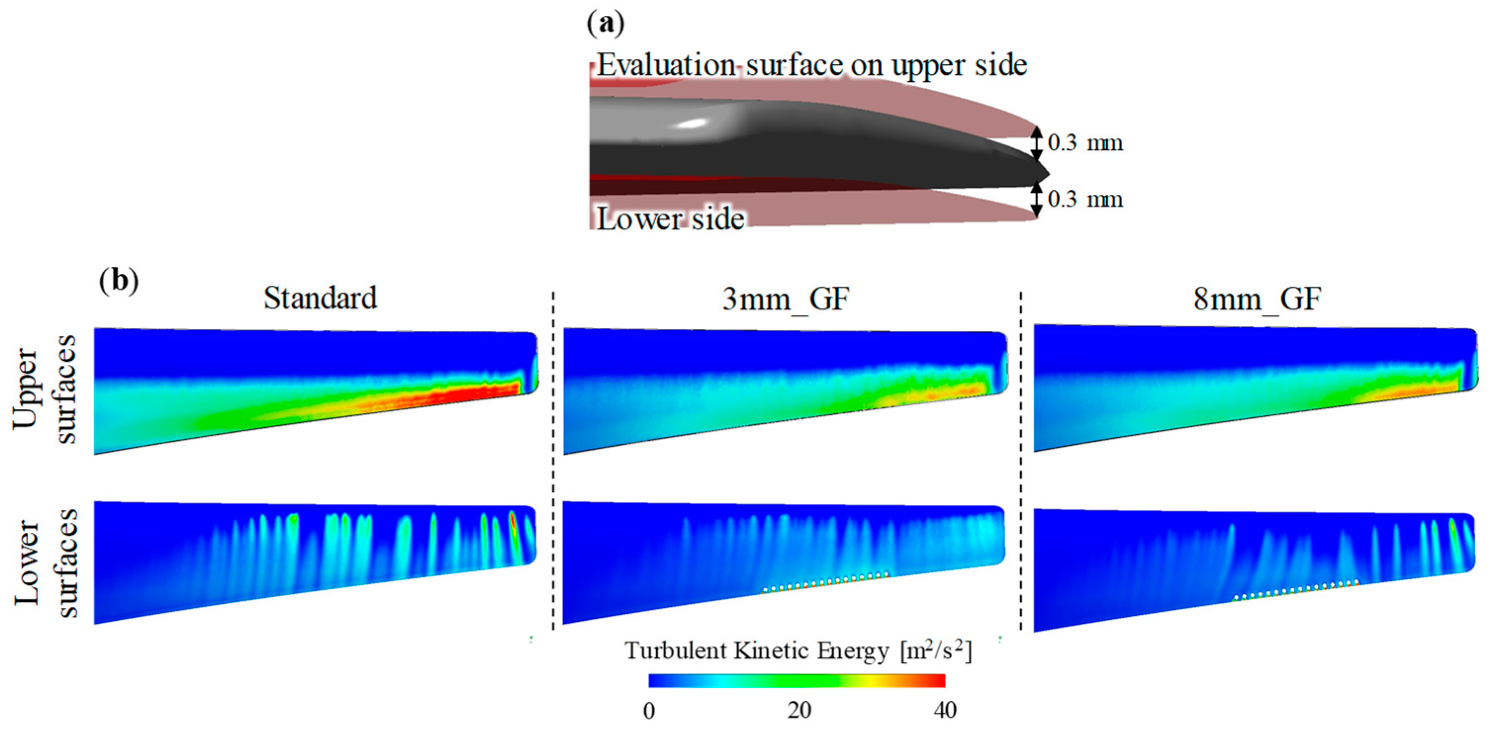
Turbulence Kinetic Energy (TKE) given through the transport equation is characterized as the variance of velocity fluctuations and is utilized for the assessment of aeroacoustic performance [47,48]. The distributions of TKE on a virtual surface located 0.3 mm from the upper and lower surfaces are illustrated in Figure 16. For the standard propeller, a region of high TKE is observed on the trailing edge side, approximately beyond 0.8R in the spanwise direction. At the wing tip, the suppression of TKE attributed to the vortex center of the wing tip vortex can be identified. In the Gurney flap-inspired propellers, TKE is suppressed on the trailing edge side, especially on the upper surfaces, compared to the standard propeller. These suppressions of TKE are believed to result from the combined effects of the decrease in rotational speed and the induction of downward velocity in the flow on the upper surface caused by the low-pressure region near the trailing edge generated by the imparting structures. The imparting structure with gaps in this study possesses characteristics resembling serrations found in flying organisms such as owls. The application of serrated profiles to the trailing edge of fixed wings (not vertically oriented, as in this study) has been extensively studied, resulting in reported noise reduction effects, including significant narrowband noise reduction due to decreased shedding vortices at the trailing edge [49] and reduction in broadband noise through non-flat plate serrations [50], even in the rotating wing models [51]. In this study, the Gurney flap-inspired propellers also achieved a consistent broadband noise reduction above 1 kHz (see Figure 5b, Figure 8 and Figure 9). However, the flow field obtained from the steady-state analysis provides only limited insight into the sound mechanisms involved. For example, it is difficult to assess whether vortices generated by the imparted cylindrical structure itself could act as potential noise sources. In future studies, the noise reduction mechanism, such as the effect of spanwise coherence and destructive interference caused by this imparting structure, will be investigated through transient analysis.
In the present study, considering the computational cost, a steady-state analysis of a single propeller was conducted. As a result, potential mechanisms related to noise reduction were suggested. However, considering the trade-off between increased power consumption, as indicated by the increase in torque (Table 3) of the low-noise propellers, and the reduced amount of noise obtained from the experiments, these propellers are of limited use; therefore, for the noise reduction and the optimization of propellers in sound source localization performance with computational fluid dynamics, it will be necessary to perform transient analysis, taking into account the full interaction among the propeller, microphone array, and the fuselage of a drone, based on the results obtained in the experiments.

4. Conclusions

In this study, we investigated the impact of low-noise propellers inspired by Gurney flaps on the acoustic characteristics and sound source localization performance in both acoustic near- and far-field environments. In addition, we investigated the noise reduction mechanisms of these propellers using CFD simulations. The results of the in-flight noise measurements demonstrated that the low-noise propellers exhibited significant noise reduction effects at all measured positions of the microphone in the far-field environment. In particular, the most significant noise reduction effect was observed at the position closest to the drone, mainly due to a reduction in the frequency range from 800 Hz to 10 kHz, achieving an overall noise reduction of approximately 2 dBA compared to the standard propeller. Similar results were observed in the near-field measurements using a spherical microphone array mounted on the drone. However, when evaluating the spatial spectrum of the lower hemisphere of a spherical microphone array for sound source localization, assuming the search source is below the drone, it was found that the noise reduction effect due to the positional relationship between the propeller and the microphone array was more pronounced than the effect due to propeller shape manipulation. This highlights the importance of considering the mounting position of the microphone array with respect to the propeller position. Evaluation of sound source localization performance using three different methods demonstrated an improvement in the success rate of sound source localization with low-noise propellers in all the methods. However, the lack of correlation between the reduction rate of noise levels and the success rate of sound source localization suggests that the overall sound pressure level and its spectral analysis evaluations in the present study can only provide limited information for optimizing propeller design to improve sound source localization performance. A comprehensive design that improves sound source localization performance would not only require consideration of reducing the overall noise level but also take into account the characteristics of each sound source localization method. For example, it would be necessary to consider results of acoustic field analysis, taking into account factors such as the temporal variations in noise at each microphone position and its spatial distribution. Finally, a flow field analysis of the propeller using numerical simulations suggested one of the potential noise reduction mechanisms for the propellers used in this study. The findings from this study hold potential to contribute to the development of integrated propellers for reducing noise and improving sound source localization performance in drones.

Author Contributions

Conceptualization, R.N., K.H. and T.N.; methodology, R.N. and K.H.; validation, R.N.; formal analysis, R.N., I.K. and K.H.; investigation, R.N. and K.H.; data curation, R.N.; writing—original draft preparation, R.N. and K.H.; writing—review and editing, R.N., K.H., T.N. and H.L.; visualization, R.N.; project administration, R.N.; funding acquisition, R.N., K.H. and H.L. All authors have read and agreed to the published version of the manuscript.

Funding

This work was supported by JSPS KAKENHI grant no. JP19H00750 and partially supported by JSPS KAKENHI grant nos. JP23K03733, JP22K14218, and JP23H01373.

Data Availability Statement

The data generated and/or analyzed as well as the source code used in the current study are not publicly available due to their use in an ongoing project but may be available from the corresponding author on reasonable request.

Conflicts of Interest

The authors declare no conflicts of interest.

References

  1. Nonami, K. Drone Technology, Cutting-Edge Drone Business, and Future Prospects. J. Robot. Mechatron. 2016, 28, 262–272. [Google Scholar] [CrossRef]
  2. Rothstein, A. Drone; Bloomsbury Publishing: New York, NY, USA, 2015. [Google Scholar]
  3. Gwak, D.Y.; Han, D.; Lee, S. Sound Quality Factors Influencing Annoyance from Hovering UAV. J. Sound Vib. 2020, 489, 115651. [Google Scholar] [CrossRef]
  4. Schäffer, B.; Pieren, R.; Heutschi, K.; Wunderli, J.M.; Becker, S. Drone Noise Emission Characteristics and Noise Effects on Humans—A Systematic Review. Int. J. Environ. Res. Public Health 2021, 18, 5940. [Google Scholar] [CrossRef] [PubMed]
  5. Tan, Q.; Bian, H.; Guo, J.; Zhou, P.; Lo, H.K.; Zhong, S.; Zhang, X. Virtual Flight Simulation of Delivery Drone Noise in the Urban Residential Community. Transp. Res. Part D Transp. Environ. 2023, 118, 103686. [Google Scholar] [CrossRef]
  6. Bian, H.; Tan, Q.; Zhong, S.; Zhang, X. Assessment of UAM and Drone Noise Impact on the Environment Based on Virtual Flights. Aerosp. Sci. Technol. 2021, 118, 106996. [Google Scholar] [CrossRef]
  7. Ramos-Romero, C.; Green, N.; Roberts, S.; Clark, C.; Torija, A.J. Requirements for Drone Operations to Minimise Community Noise Impact. Int. J. Environ. Res. Public Health 2022, 19, 9299. [Google Scholar] [CrossRef] [PubMed]
  8. Ffowcs Williams, J.E.; Hawkings, D.L. Sound Generation by Turbulence and Surfaces in Arbitrary Motion. Phil. Trans. R. Soc. Lond. A 1969, 264, 321–342. [Google Scholar] [CrossRef]
  9. Williams, J.F.; Hawkings, D.L. Theory Relating to the Noise of Rotating Machinery. J. Sound Vib. 1969, 10, 10–21. [Google Scholar] [CrossRef]
  10. Farassat, F. Theory of Noise Generation from Moving Bodies with an Application to Helicopter Rotors; National Aeronautics and Space Administration: Washington, DC, USA, 1975.
  11. Noda, R.; Nakata, T.; Ikeda, T.; Chen, D.; Yoshinaga, Y.; Ishibashi, K.; Rao, C.; Liu, H. Development of Bio-Inspired Low-Noise Propeller for a Drone. J. Robot. Mechatron. 2018, 30, 337–343. [Google Scholar] [CrossRef]
  12. Shima, E.; Tsutsumi, S.; Fujimoto, K. Preliminary Study on Innovative Loop Propellers for Quiet eVTOL. In Proceedings of the 8th Asian/Australian Rotorcraft Forum, Ankara, Turkey, 30 October–2 November 2019; Volume 30. [Google Scholar]
  13. Sun, J.; Yonezawa, K.; Shima, E.; Liu, H. Integrated Evaluation of the Aeroacoustics and Psychoacoustics of a Single Propeller. Int. J. Environ. Res. Public Health 2023, 20, 1955. [Google Scholar] [CrossRef]
  14. Yao, H.-D.; Huang, Z.; Davidson, L.; Niu, J.; Chen, Z.-W. Blade-Tip Vortex Noise Mitigation Traded-Off against Aerodynamic Design for Propellers of Future Electric Aircraft. Aerospace 2022, 9, 825. [Google Scholar] [CrossRef]
  15. Wei, Y.; Xu, F.; Bian, S.; Kong, D. Noise Reduction of UAV Using Biomimetic Propellers with Varied Morphologies Leading-Edge Serration. J. Bionic Eng. 2020, 17, 767–779. [Google Scholar] [CrossRef]
  16. Wei, Y.; Qian, Y.; Bian, S.; Xu, F.; Kong, D. Experimental Study of the Performance of a Propeller with Trailing-Edge Serrations. Acoust. Aust. 2021, 49, 305–316. [Google Scholar] [CrossRef]
  17. Li, Y.; Yang, Y.; Liu, Y.; Wang, Y.; Huang, B.; Li, W. Aerodynamic and Aeroacoustic Analyses of a UAV Propeller with Trailing Edge Serrations. In Proceedings of the ACOUSTICS, Ustka, Poland, 11–14 September 2018; Volume 7. [Google Scholar]
  18. Gu, Y.; Song, F.; Bai, H.; Wu, J.; Liu, K.; Nie, B.; Wang, L.; Zhang, Z.; Lu, Z. Numerical and Experimental Studies on the Owl-Inspired Propellers with Various Serrated Trailing Edges. Appl. Acoust. 2024, 220, 109948. [Google Scholar] [CrossRef]
  19. Hasegawa, M.; Sakaue, H. Propeller-Noise Reduction by Microfiber Coating on a Blade Surface. Sens. Actuators A Phys. 2024, 371, 115273. [Google Scholar] [CrossRef]
  20. Liebeck, R.H. Design of Subsonic Airfoils for High Lift. J. Aircr. 1978, 15, 547–561. [Google Scholar] [CrossRef]
  21. Storms, B.L.; Jang, C.S. Lift Enhancement of an Airfoil Using a Gurney Flap and Vortex Generators. J. Aircr. 1994, 31, 542–547. [Google Scholar] [CrossRef]
  22. Li, Y.; Wang, J.; Zhang, P. Effects of Gurney Flaps on a NACA0012 Airfoil. Flow Turbul. Combust. 2002, 68, 27–39. [Google Scholar] [CrossRef]
  23. Wang, J.J.; Li, Y.C.; Choi, K.-S. Gurney Flap—Lift Enhancement, Mechanisms and Applications. Prog. Aerosp. Sci. 2008, 44, 22–47. [Google Scholar] [CrossRef]
  24. Yee, K.; Joo, W.; Lee, D.-H. Aerodynamic Performance Analysis of a Gurney Flap for Rotorcraft Application. J. Aircr. 2007, 44, 1003–1014. [Google Scholar] [CrossRef]
  25. Yao, Y.; Ma, D.; Zhang, L.; Yang, X.; Yu, Y. Aerodynamic Optimization and Analysis of Low Reynolds Number Propeller with Gurney Flap for Ultra-High-Altitude Unmanned Aerial Vehicle. Appl. Sci. 2022, 12, 3195. [Google Scholar] [CrossRef]
  26. Ye, X.; Zheng, N.; Hu, J.; Li, C.; Xue, Z. Numerical Investigation of the Benefits of Serrated Gurney Flaps on an Axial Flow Fan. Energy 2022, 252, 124072. [Google Scholar] [CrossRef]
  27. Kurtz, D.W.; Marte, J.E. A Review of Aerodynamic Noise from Propellers, Rotors, and Lift Fans; Technical Report; Jet Propulsion Laboratory, California Institute of Technology: Pasadena, CA, USA, 1970; pp. 32–1462. [Google Scholar]
  28. Wilson, C.E. Noise Control: Measurement, Analysis, and Control of Sound and Vibration; Krieger Pub Co.: Malabar, FL, USA, 1989. [Google Scholar]
  29. Noda, R.; Ikeda, T.; Nakata, T.; Liu, H. Characterization of the Low-Noise Drone Propeller with Serrated Gurney Flap. Front. Aerosp. Eng. 2022, 1, 1004828. [Google Scholar] [CrossRef]
  30. Quan, A.; Herrmann, C.; Soliman, H. Project Vulture: A Prototype for Using Drones in Search and Rescue Operations. In Proceedings of the 2019 15th International Conference on Distributed Computing in Sensor Systems (DCOSS), Santorini Island, Greece, 29–31 May 2019; pp. 619–624. [Google Scholar]
  31. Sambolek, S.; Ivasic-Kos, M. Automatic Person Detection in Search and Rescue Operations Using Deep CNN Detectors. IEEE Access 2021, 9, 37905–37922. [Google Scholar] [CrossRef]
  32. Hoshiba, K.; Washizaki, K.; Wakabayashi, M.; Ishiki, T.; Kumon, M.; Bando, Y.; Gabriel, D.; Nakadai, K.; Okuno, H.G. Design of UAV-Embedded Microphone Array System for Sound Source Localization in Outdoor Environments. Sensors 2017, 17, 2535. [Google Scholar] [CrossRef]
  33. Zhou, T.; Fattah, R. Tonal Noise Characteristics of Two Small-Scale Propellers. AIAA Pap. 2017, 4054, 2017. [Google Scholar]
  34. Schmidt, R. Multiple Emitter Location and Signal Parameter Estimation. IEEE Trans. Antennas Propag. 1986, 34, 276–280. [Google Scholar] [CrossRef]
  35. Okutani, K.; Yoshida, T.; Nakamura, K.; Nakadai, K. Outdoor Auditory Scene Analysis Using a Moving Microphone Array Embedded in a Quadrocopter. In Proceedings of the 2012 IEEE/RSJ International Conference on Intelligent Robots and Systems, Algarve, Portugal, 7–12 October 2012; pp. 3288–3293. [Google Scholar]
  36. Hoshiba, K.; Nakadai, K.; Kumon, M.; Okuno, H.G. Assessment of MUSIC-Based Noise-Robust Sound Source Localization with Active Frequency Range Filtering. J. Robot. Mechatron. 2018, 30, 426–435. [Google Scholar] [CrossRef]
  37. Menter, F.R.; Kuntz, M.; Langtry, R. Ten Years of Industrial Experience with the SST Turbulence Model. Turbul. Heat Mass Transf. 2003, 4, 625–632. [Google Scholar]
  38. Ellington, C.P. The Aerodynamics of Hovering Insect Flight. V. A Vortex Theory. Phil. Trans. R. Soc. Lond. B 1984, 305, 115–144. [Google Scholar] [CrossRef]
  39. Zhang, X.; Sciacchitano, A.; Pröbsting, S. Aeroacoustic Analysis of an Airfoil with Gurney Flap Based on Time-Resolved Particle Image Velocimetry Measurements. J. Sound Vib. 2018, 422, 490–505. [Google Scholar] [CrossRef]
  40. Cussen, K.; Garruccio, S.; Kennedy, J. UAV Noise Emission–a Combined Experimental and Numerical Assessment. Acoustics 2022, 4, 297–312. [Google Scholar] [CrossRef]
  41. Kloet, N.; Watkins, S.; Clothier, R. Acoustic Signature Measurement of Small Multi-Rotor Unmanned Aircraft Systems. Int. J. Micro Air Veh. 2017, 9, 3–14. [Google Scholar] [CrossRef]
  42. Heutschi, K.; Ott, B.; Nussbaumer, T.; Wellig, P. Synthesis of Real World Drone Signals Based on Lab Recordings. Acta Acust. 2020, 4, 24. [Google Scholar] [CrossRef]
  43. Miljković, D. Methods for Attenuation of Unmanned Aerial Vehicle Noise. In Proceedings of the 2018 41st International Convention on Information and Communication Technology, Electronics and Microelectronics (MIPRO), Opatija, Croatia, 21–25 May 2018; pp. 0914–0919. [Google Scholar]
  44. Alkmim, M.; Cardenuto, J.; Tengan, E.; Dietzen, T.; Van Waterschoot, T.; Cuenca, J.; De Ryck, L.; Desmet, W. Drone Noise Directivity and Psychoacoustic Evaluation Using a Hemispherical Microphone Array. J. Acoust. Soc. Am. 2022, 152, 2735–2745. [Google Scholar] [CrossRef]
  45. Hoshiba, H.; Noda, R.; Nakata, T.; Liu, H.; Senda, K.; Nakadai, K.; Okuno, H.G. Development of Surface-Processed Low-Noise Propeller for Search and Rescue Tasks with Drone Audition. In Proceedings of the Quiet Drones International e-Symposium on UAV/UAS Noise, Paris, France, 19–21 October 2020. [Google Scholar]
  46. Xie, Y.H.; Jiang, W.; Lu, K.; Zhang, D. Numerical Investigation into Energy Extraction of Flapping Airfoil with Gurney Flaps. Energy 2016, 109, 694–702. [Google Scholar] [CrossRef]
  47. Glegg, S.; Morin, B.; Atassi, O.; Reba, R. Using RANS Calculations of Turbulent Kinetic Energy to Provide Predictions of Trailing Edge Noise. In Proceedings of the 14th AIAA/CEAS Aeroacoustics Conference (29th AIAA Aeroacoustics Conference), Vancouver, BC, Canada, 5–7 May 2008; American Institute of Aeronautics and Astronautics: Reston, VA, USA, 2008. [Google Scholar]
  48. Remmler, S.; Christophe, J.; Anthoine, J.; Moreau, S. Computation of Wall Pressure Spectra from Steady Flow Data for Noise Prediction. AIAA J. 2010, 48, 1997–2007. [Google Scholar] [CrossRef]
  49. Moreau, D.J.; Doolan, C.J. Noise-Reduction Mechanism of a Flat-Plate Serrated Trailing Edge. AIAA J. 2013, 51, 2513–2522. [Google Scholar] [CrossRef]
  50. Chong, T.P.; Joseph, P.F.; Gruber, M. Airfoil Self Noise Reduction by Non-Flat Plate Type Trailing Edge Serrations. Appl. Acoust. 2013, 74, 607–613. [Google Scholar] [CrossRef]
  51. Lee, H.M.; Lu, Z.; Lim, K.M.; Xie, J.; Lee, H.P. Quieter Propeller with Serrated Trailing Edge. Appl. Acoust. 2019, 146, 227–236. [Google Scholar] [CrossRef]
Figure 1. (a) The three types of propeller shapes used in the present study and (b) an enlarged diagram of the imparting structure of the model with a height of 3 mm.
Drones 08 00265 g001
Figure 2. (a) Experimental setup for force and noise measurements on a single propeller. (b) Position of the microphone for noise measurements in the outdoors. (c) Outdoor environment.
Drones 08 00265 g002
Figure 3. (a) Drone with spherical microphone array and its coordinate system. (b) Schematic of a drone with a spherical microphone array (dotted circles) shown in the top and side views. The colors red, green, and blue correspond to positions at L = 300, 450, and 600 mm, respectively. (c) Microphone positions in the microphone array.
Drones 08 00265 g003
Figure 4. Hybrid grid system for the (a) static and (b) rotating domains. (c) Surface meshes of the standard propeller.
Drones 08 00265 g004
Figure 5. (a) Effects of the Gurney flap-inspired structures on the FM and the SPL. (b) Frequency spectrum of noise from the tested propellers. Dark solid lines indicate the moving averages.
Drones 08 00265 g005
Figure 6. Overall SPLs in the in-flight experiment for the tested propellers.
Drones 08 00265 g006
Figure 7. The averaged results of the spectral analysis of the measured noise at horizontal positions of (a) 3.0, (b) 4.5, and (c) 6.0 m.
Drones 08 00265 g007
Figure 8. Differences in the one-third octave band spectra between the Gurney flap-inspired propellers and the standard propeller at the horizontal positions of (a) 3.0, (b) 4.5, and (c) 6.0 m.
Drones 08 00265 g008
Figure 9. Frequency spectrum of noise recorded by the drone-mounted microphone array at L = (a) 600, (b) 450, and (c) 300 mm.
Drones 08 00265 g009
Figure 10. Setting of the coordinate system of azimuth angle θ and elevation angle ϕ when plotting spatial spectra.
Drones 08 00265 g010
Figure 11. Spatial noise spectra calculated by SEVD-MUSIC for analysis frequency of 1.5 to 3 kHz for the (a) standard, (b) 3 mm_GF, and (c) 8 mm_GF models with L = (i) 600 mm, (ii) 450 mm, and (iii) 300 mm.
Drones 08 00265 g011
Figure 12. Standard deviation of the spatial spectra shown in Figure 11 for the (a) standard, (b) 3 mm_GF, and (c) 8 mm_GF models with L = (i) 600 mm, (ii) 450 mm, and (iii) 300 mm.
Drones 08 00265 g012
Figure 13. Example of spatial spectrum of evaluation signal.
Drones 08 00265 g013
Figure 14. Success rate of sound source localization. (a) SEVD-MUSIC, (b) iGEVD-MUSIC, and (c) AFRF-MUSIC. L = (i) 600 mm, (ii) 450 mm, and (iii) 300 mm.
Drones 08 00265 g014
Figure 15. (a) Pressure distribution on the upper and lower surfaces of three propellers. (b) Pressure distribution on the cross section at 0.8R.
Drones 08 00265 g015
Figure 16. (a) Evaluation surfaces. (b) Turbulent kinetic energy distributions on the evaluation surfaces on the upper and lower sides.
Drones 08 00265 g016
Table 1. Parameter of a standard propeller.
Propeller diameter [mm]380.40
Hub diameter [mm]27.39
Wing length, R [mm]190.20
Mean chord length, cm [mm]25.47
Rotational speed, Urot [rpm]4100
Wing tip velocity, Uref [m/s]81.66(Uref = 2πRUrot/60)
Reynolds number, Re [-]1.35 × 10⁵(Re = cmUref/ν)
Table 2. Operating conditions of the tested propellers.
Standard3 mm_GF8 mm_GF
First layer [mm]0.0120.0120.012
Prism layers151515
Propeller surface mesh size [mm]0.30.30.3
Total element number (×106)9.4611.8712.05
Rotational speed [rpm]410039003800
Reynolds number [-]1.35 × 1051.28 × 1051.25 × 105
Table 3. Resultant force and torque from the numerical simulation.
Standard3 mm_GF8 mm_GF
Lift [N]3.7983.850 (+1.3%)3.740 (−1.5%)
Drag [N]0.6620.740 (+11.8%)0.819 (+23.6%)
Lift-to-drag ratio [-]5.7345.200 (−9.3%)4.568 (−20.3%)
Torque [N·m]0.0780.091 (+16.7%)0.103 (+32.4%)
Disclaimer/Publisher’s Note: The statements, opinions and data contained in all publications are solely those of the individual author(s) and contributor(s) and not of MDPI and/or the editor(s). MDPI and/or the editor(s) disclaim responsibility for any injury to people or property resulting from any ideas, methods, instructions or products referred to in the content.