Article

Efficient Motion Primitives-Based Trajectory Planning for UAVs in the Presence of Obstacles

Dipartimento di Scienze e Tecnologie Aerospaziali, Politecnico di Milano, Via La Masa 34, 20156 Milano, Italy
*
Author to whom correspondence should be addressed.
Drones 2024, 8(6), 256; https://doi.org/10.3390/drones8060256
Submission received: 6 May 2024 / Revised: 4 June 2024 / Accepted: 6 June 2024 / Published: 12 June 2024

Abstract

:
The achievement of full autonomy in Unmanned Aerial Vehicles (UAVs) is significantly dependent on effective motion planning. Specifically, it is crucial to plan collision-free trajectories for smooth transitions from initial to final configurations. However, finding a solution executable by the actual system adds complexity: the planned motion must be dynamically feasible. This involves meeting rigorous criteria, including vehicle dynamics, input constraints, and state constraints. This work addresses optimal kinodynamic motion planning for UAVs in the presence of obstacles by employing a hybrid technique instead of conventional search-based or direct trajectory optimization approaches. This technique involves precomputing a library of motion primitives by solving several Two-Point-Boundary-Value Problems (TPBVP) offline. This library is then repeatedly used online within a graph-search framework. Moreover, to make the method computationally tractable, continuity between consecutive motion primitives is enforced only on a subset of the state variables. This approach is compared with a state-of-the-art quadrotor-tailored search-based approach, which generates motion primitives online through control input discretization and forward propagation of the dynamic equations of a simplified model. The effectiveness of both methods is assessed through simulations and real-world experiments, demonstrating their ability to generate resolution-complete, resolution-optimal, collision-free, and dynamically feasible trajectories. Finally, a comparative analysis highlights the advantages, disadvantages, and optimal usage scenarios for each approach.

1. Introduction

Unmanned Aerial Vehicles (UAVs) have achieved significant popularity in recent years, enabling autonomous flight without the need for human pilots. The versatility of UAVs is evident in their autonomous navigation and task execution, including a wide range of applications in both civilian and military domains. These applications span surveillance, reconnaissance, package delivery, and exploration [1]. However, as the roles of UAVs evolve, navigating complex environments with agility becomes crucial. While path-planning algorithms ensure collision-free paths, their execution by the actual system may not be feasible. This is especially evident in agile vehicles, where additional limitations from dynamics or nonholonomic constraints must be considered. Kinodynamic motion planning addresses this issue, considering vehicle dynamics, input constraints, and state constraints.
Frazzoli et al. [2,3] provided some of the pioneering work on real-time kinodynamic motion planning. The proposed technique involves mapping the dynamics of the vehicle onto a finite-dimensional space, restricting the vehicle’s potential states to two categories: either a trim state or a maneuver state. Since then, the field has seen significant progress, yielding numerous trajectory-generation algorithms. Many researchers have adopted a two-step approach, separating geometric and temporal planning. Initially, an optimal collision-free geometric path is generated by linking a series of waypoints by straight lines. Subsequently, the path is smoothed and parameterized in time to ensure compliance with the vehicle dynamics. This smoothing step can be performed in various ways. For instance, one approach involves selecting the optimal sequence of trims and maneuvers from a precomputed library of motion primitives [4]. Alternatively, a sequence of polynomial segments can be jointly optimized to connect waypoints into a smooth trajectory from start to goal [5]. These two-step strategies significantly simplify the planning problem. However, the initial geometric path does not consider the dynamics of the vehicle, restricting the resulting trajectory to a specific homology class. This limitation may exclude the possibility of achieving a globally optimal (or even feasible) trajectory. Moreover, the final smoothed trajectory is not guaranteed to be obstacle-free.
Several studies have adopted a direct trajectory-generation approach that integrates the vehicle dynamics from the beginning, bypassing the two-step process. Many of these works leverage the inherent differential flatness property of quadrotor dynamics to represent trajectories using time-parameterized polynomials [6,7,8,9]. This transforms the trajectory-generation problem into the task of determining polynomial coefficients that meet specific constraints. While this approach has been extensively studied and applied in the context of quadrotors [6,7,8,9,10], its applicability is limited to systems with similar dynamics. Extending this methodology to more complex systems such as Vertical Take-Off and Landing (VTOL) and fixed-wing aircraft presents significant challenges.
Other stream of research use methods based on direct trajectory optimization, such as [11,12,13,14], to design trajectories that account for the full system dynamics. However, converting the planning problem into a non-convex optimization problem and using local optimization techniques can fail to find a collision-free trajectory in cluttered environments. Additionally, most trajectory optimization methods are prone to becoming stuck in local minima. Consequently, there is growing interest in constructing global solutions for motion planning problems. Early attempts to address this challenge formulated the problem as a single optimization problem using a mixed-integer optimization approach [15,16]. However, this method is tractable only for a limited number of obstacles. More recent approaches, such as those exploiting convex decomposition of the environment [17], allow for efficient computation but struggle with nonlinear dynamics, as this would result in a mixed-integer nonlinear problem, which is computationally intractable.
Motion primitives offer a promising alternative by combining the strengths of optimal control, which can handle arbitrary dynamics, with the effectiveness of graph-based algorithms that perform global searches in non-convex configuration spaces. This paper investigates motion primitives-based methods for addressing quadrotor kinodynamic motion planning, focusing on two main approaches. One approach [8] generates motion primitives online through control input discretization and forward propagation of the dynamic equations of a simplified model, serving as a benchmark for comparison. Additionally, the approach presented in [18] is revised and customized for quadrotor kinodynamic motion planning. Specifically, the differential flatness property of quadrotors is exploited to construct a library of precomputed trajectories during an offline phase. This library is then used online to concatenate the motion primitives using a search-based framework to obtain a complete trajectory. Moreover, to make the method computationally tractable, continuity between consecutive motion primitives is enforced only on a subset of the state variables (position, velocity, and acceleration). The methods are compared through both numerical simulations and real-world experiments to highlight the strengths and weaknesses of each approach.
The remainder of this paper is organized as follows: Section 2 provides an overview of the quadrotor model and its differential flatness property. Section 3 formulates the kinodynamic motion planning problem. Section 4 introduces the methodology presented in [18], aimed at generating an offline library of motion primitives tailored for systems with arbitrary dynamics. This method is then adapted to suit the quadrotor system within a search-based framework. Additionally, continuity between consecutive motion primitives is enforced on a subset of state variables to enhance computational tractability. Section 5 introduces the state-of-the-art approach proposed in [8], serving as a benchmark for comparison. Here, motion primitives for quadrotors are generated online through input discretization and forward propagation, employing a simplified model of vehicle dynamics. Section 6 presents the numerical results. Section 7 details the experimental outcomes. Finally, Section 8 offers a comparative analysis of the two methods, while Section 9 draws conclusions and delineates potential directions for future research.
Notation: R ( R > 0 , R 0 ) denotes the set of (positive, nonnegative) real numbers, R n denotes the n-dimensional real coordinate space and R m × n the set of m × n real matrices. Given x R n , y R m , denote ( x , y ) : = [ x , y ] .
The i-th vector of the canonical basis in R n is denoted e i and the identity matrix in R n × n is I n : = [ e 1 e i e n ] . Given vectors x , y R n , the standard inner product is defined as x , y : = x y . The Euclidean norm of a vector x R n is x : = x , x .
The n-dimensional unit sphere is denoted as S n : = { x R n + 1 : x = 1 } . The set SO ( 3 ) : = { R R 3 × 3 : R R = I 3 , d e t ( R ) = 1 } is the 3D Special Orthogonal group. The map S ( · ) : R 3 so 3 : = { W R 3 × 3 : W = W } is defined such that given x , y R 3 one has S ( x ) y = x × y .

2. Quadrotor Model

The quadrotor is modeled as a rigid body with six degrees of freedom (DOFs). The differential equations governing the flight are [19]
p ˙ = v m v ˙ = m g e 3 + t c R e 3 R ˙ = R S ( ω ) J ω ˙ = S ( ω ) J ω + τ c .
In this formulation, p = ( x , y , z ) R 3 and v = ( x ˙ , y ˙ , z ˙ ) R 3 represent the position and velocity of the quadrotor in the inertial frame, respectively. R SO ( 3 ) is the rotation matrix describing the orientation of the body frame relative to the inertial frame, and ω R 3 denotes the angular velocity vector in the body frame. m R > 0 is the quadrotor mass while J = J R 3 × 3 is its inertia matrix with respect to the center of mass. t c R > 0 denotes the thrust in the body frame and τ c R 3 is a vector of three body torques. Finally, g = 9.81 ms−2 represents the gravity acceleration and e 3 = ( 0 , 0 , 1 ) .

2.1. Differential Flatness

Equation (1) is inherently nonlinear and complex to manage. Nevertheless, the differential flatness property inherent to quadrotor systems can be leveraged to significantly simplify the motion planning problem [5] and the tracking problem [20]. As demonstrated in [21], the quadrotor is a flat system characterized by the following flat outputs:
σ = ( p , ψ ) R 4 ,
where σ is the vector containing the flat outputs. Specifically, these outputs consist of the coordinates of the center of mass, denoted as p, and the yaw angle ψ .
Differential flatness implies that all the state variables x = ( p , v , R , ω ) R 12 and control inputs u = ( t c , τ c ) R 4 can be written as algebraic functions of the flat outputs and a finite number of their derivatives. As a consequence, any trajectory in the state of the flat output is flyable as long as the flat outputs and their derivatives satisfy specific smoothness conditions. In particular, the position p must be at least four times differentiable, while the yaw angle ψ must be at least twice differentiable (see Appendix A for further details).

3. Kinodynamic Motion Planning: Problem Statement

Kinodynamic motion planning aims to find the optimal trajectory for a vehicle navigating from an initial state x i to a final state x f while considering both its kinematics and dynamics.
The kinodynamic motion planning problem can be formulated as an optimization problem, with the aim of finding the input functions u ( t ) , the corresponding state trajectories x ( t ) , and the total duration T that minimize the cost function J, all while adhering to specified constraints. The formulation is as follows:
(3a) min x ( t ) , u ( t ) , T J = 0 T u ( t ) 2 d t + ρ T (3b) s . t . x ˙ = f ( x ( t ) , u ( t ) ) , t [ 0 , T ] (3c) x ( t ) X , t [ 0 , T ] (3d) u ( t ) U , t [ 0 , T ] (3e) x ( 0 ) = x i , (3f) x ( T ) = x f .
Equation (3a) defines the cost function, which aims to strike a balance between minimizing the total time T and minimizing the control effort required for the trajectory. This balance is governed by the weight parameter ρ . Equation (3b) enforces the system’s dynamics outlined in Equation (1). Equation (3c) describes the state constraints, which consist of obstacle avoidance (non-convex) and limits on velocity and acceleration. Equation (3d) represents the control input constraints. The initial and final states in Equation (3e) and Equation (3f) correspond to the boundary conditions.
Explicitly solving Problem (3) is hard due to states and input constraints, as well as the non-convex nature of obstacle avoidance. An effective strategy to alleviate the computational load associated with motion planning involves transforming the problem into a graph-search problem. This method involves choosing a finite set of candidate solutions known as motion primitives. Motion primitives represent a collection of precomputed motions tailored for specific dynamic systems. These precalculated solutions address sub-problems, which can be concatenated to form a complete trajectory that effectively resolves the motion planning problem.
A motion primitive can be generated through various methodologies, including solving a Two-Point-Boundary-Value Problem (TPBVP) (see Section 4) or forward integration of the state equations (see Section 5). Additionally, motion primitives can be generated offline and stored in a database when dealing with complex systems (see Section 4) or generated online when a simplified model accurately represents the dynamics of the system (see Section 5).

4. Search-Based Kinodynamic Planning with Motion Primitives Library for Differentially Flat Quadrotors

This section builds upon the work presented in [18], which addresses motion planning for systems with arbitrary dynamics through a two-phase approach: offline and online. During the offline phase, the state space is discretized to obtain a suitable number of initial and final condition pairs. Motion primitives are then computed as solutions to a TPBVP, using these initial and final conditions as boundary conditions. Finally, these motion primitives are stored in a library. This process shifts the computational demands of trajectory generation to the offline phase, significantly reducing the computational load during online motion planning. In the online phase, the task of the planner is to select suitable motion primitives from the library to generate a complete trajectory. This two-phase approach enables efficient online motion planning for various systems, including complete quadrotor models as well as more complex systems like fixed-wing and VTOL aircraft.
In this section, this methodology is modified by tailoring it specifically to the quadrotor system, leveraging its inherent differential flatness property. Moreover, to make the method computationally tractable, continuity between consecutive motion primitives is enforced only on a subset of the state variables. Finally, the original approach is modified by utilizing a search-based planner rather than a sampling-based one.

4.1. Motion Primitives Library

Given an initial and a final condition, a motion primitive is the solution to the following TPBVP:
min x ( t ) , u ( t ) , τ J = 0 τ u ( t ) 2 d t + ρ τ s . t . x ˙ = f ( x ( t ) , u ( t ) ) , t [ 0 , τ ] x ( t ) X , t [ 0 , τ ] u ( t ) U , t [ 0 , τ ] x ( 0 ) = x i , x ( τ ) = x f .
Unlike the TPBVP presented in Problem (3), this formulation focuses solely on generating a short-duration motion primitive rather than solving the overall motion planning problem. Consequently, the total trajectory duration T is replaced with the primitive duration τ , and the final state x f is no longer the goal; instead, it is determined by the desired state space discretization.
In traditional TPBVPs, enforcing system dynamics as constraints can be complex and computationally demanding. However, for flat quadrotor systems, since all state variables x and control inputs u can be expressed in terms of flat outputs σ = ( p , ψ ) and their derivatives, Problem (4) can be reformulated in the space of flat outputs where the system dynamics in Equation (1) are inherently satisfied (see Appendix A for further details). Moreover, when the goal is to generate a smooth trajectory, the yaw angle ψ is typically negligible, and therefore it is omitted here.
For flat quadrotors, the position along each axis can be represented as a k-th order polynomial
p ( t ) = c k t k + + c 1 t + c 0 R 3 .
The corresponding velocity v ( t ) : = p ˙ ( t ) , acceleration a ( t ) : = p ¨ ( t ) and jerk j ( t ) : = p ( t ) can be obtained by taking the derivatives of Equation (5). Then, Problem (4) can be reformulated as follows:
minimize τ , c i , i = 1 : k J = 0 τ p ( q ) ( t ) 2 d t + ρ τ s . t . p ˙ ( t ) v m a x , t [ 0 , τ ] p ¨ ( t ) a m a x , t [ 0 , τ ] p ( t ) j m a x , t [ 0 , τ ] p ( q ) ( t ) p m a x ( q ) , t [ 0 , τ ] p ( 0 ) = p i , p ( τ ) = p f p ˙ ( 0 ) = v i , p ˙ ( τ ) = v f , p ¨ ( 0 ) = a i , p ¨ ( τ ) = a f .
where p ( q ) ( t ) is the qth derivative of the position. Additional constraints, such as initial and final conditions on jerk and snap, can also be considered.
The motion primitives database is generated through an offline process where Problem (6) is solved for a suitable number of initial and final condition pairs obtained via discretization of the state space. Subsequently, the resulting optimal trajectories and optimal costs are stored in a Look-Up Table (LUT). Note that thanks to the differential flatness property, the library can be efficiently stored, as each primitive is defined by a set of coefficients c i and a duration τ .
Obstacle avoidance is not addressed at this stage of motion library generation. Once the library is computed, the planner will concatenate the motion primitives online to construct a complete trajectory while considering obstacles. To concatenate the primitives, the initial conditions of a candidate primitive must coincide with the final conditions of the previous one. Ideally, one would grid the entire state space and construct the motion primitives accordingly. However, this would result in a prohibitively large library. Therefore, in practice, these final and initial conditions are enforced only on a subset of the state variables. This ensures the continuity of the planned trajectory for this specific subset. The remaining state variables will be continuous along each motion primitive and will experience discontinuity only at the points where primitives are concatenated.
It is worth noting that in cases where a vehicle model is not available, trajectories can be obtained directly from experimental flight data [2]. Therefore, it can be safely assumed that primitives are inherently compatible with vehicle dynamics.
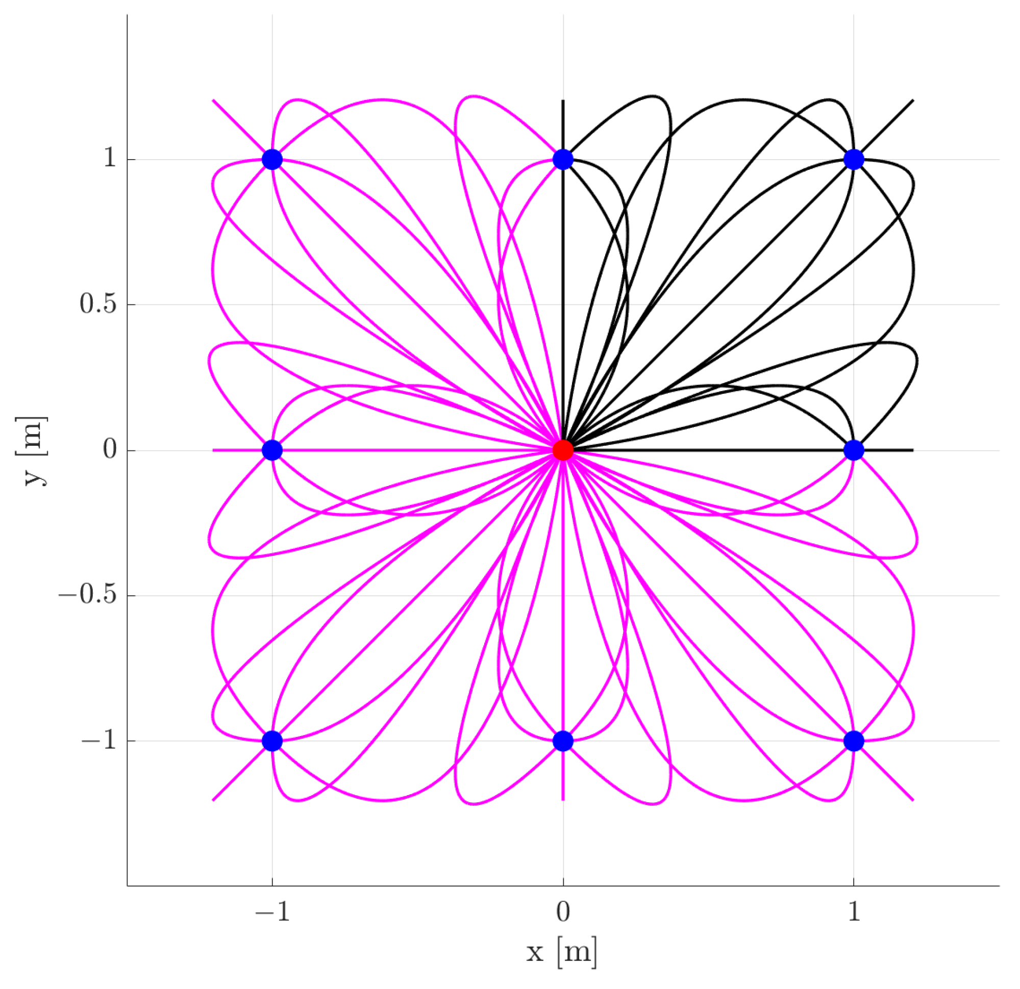
Figure 1 shows a subset of the motion primitives database for a quadrotor originating from the steady state x i = y i = v x i = v y i = 0 .

Invariance Properties

The motion primitive library can grow to include many primitives, requiring a considerable amount of memory for database storage. However, several invariance properties, extensively explored in previous works [3,22], can be leveraged to minimize this requirement.
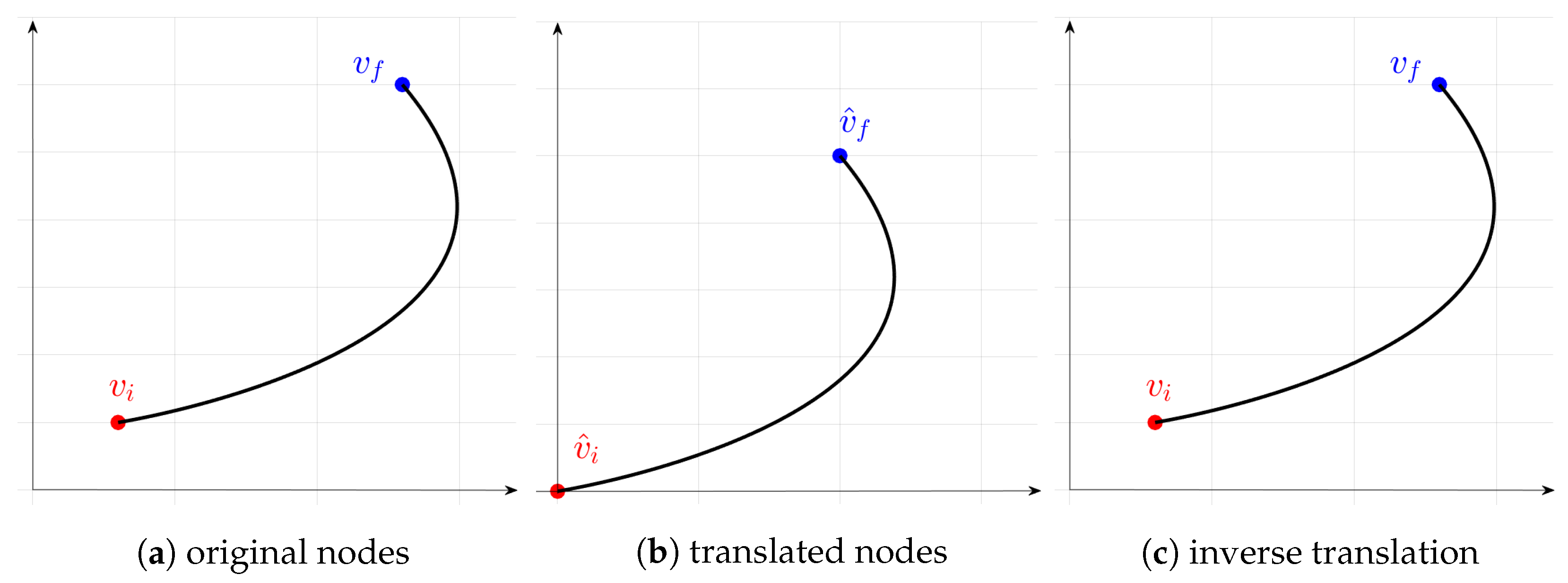
Dynamic systems, characterized by translation invariance, demonstrate consistent behavior under coordinate translations. This means that all trajectories can be rigidly translated to start from any arbitrary point. This property allows for the maintenance of a small database while covering the entire vehicle operating space. In practice, for the two-dimensional case, the initial position can be set to ( x ^ i , y ^ i ) = ( 0 , 0 ) during the database construction phase. Subsequently, the motion primitives can be easily translated to match any other initial position ( x i , y i ) , as shown in Figure 2.
In particular, a first translation is performed on the pair of initial and final states ( v i , v f ) (Figure 2a). This translation aims to relocate the initial state v i to the origin of the library (Figure 2b), resulting in a new pair of states ( v ^ i , v ^ f ) . Subsequently, a database query is executed to find the trajectory connecting these two states. Finally, an inverse translation is applied to restore the trajectory connecting the original pair of boundary states ( v i , v f ) (Figure 2c).
Additionally, specific systems, like quadrotors, possess additional invariance properties, being invariant to horizontal plane translations and rotations about the vertical axis. Observing Figure 1 it becomes evident that the motion primitives for the quadrotor are symmetric with respect to both the x- and y-axes. As a result, only trajectories within the first quadrant (depicted by black curves) need to be stored in the database. Trajectories in other quadrants (depicted by pink curves) can be generated through mirroring.

4.2. Library-Based Kinodynamic Motion Planning

The motion primitives library establishes a finite lattice discretization within the state space, enabling the construction of a graph representation G ( V , E ) . Here, V represents the set of states, and E represents the set of edges. The states in V are the initial and final conditions obtained through the state space discretization. The edges in E are defined by selecting a subset of the motion primitives library, ensuring continuity of the desired state variables with those of the previous motion primitive. Through this graph representation, the motion planning problem can be rewritten as a graph-search problem. This search problem can be solved using either search-based [8,9], or sampling-based [2,3,18,23] algorithms, which differ mainly in the optimality of the solution and computational time.
Sampling-based methods avoid the explicit construction of the configuration space by randomly or systematically sampling the space to build a graph representation of the environment. Search-based methods, on the other hand, employ traditional search algorithms to navigate a predefined representation of the configuration space. The primary distinction between these two methods lies in their approach to motion planning. Search-based methods aim to find optimal solutions, prioritizing optimality, while sampling-based methods focus on finding feasible solutions, emphasizing practicality and efficiency. Therefore, sampling-based algorithms are fast and particularly useful for complex and high-dimensional spaces. However, sampling-based methods employ a randomized approach, which could represent an obstacle when fast online replanning is required. Specifically, paths generated by sampling-based methods during successive replanning phases may exhibit significant variations, making them less suitable for applications where path consistency is crucial [9].
Based on these considerations, the A* algorithm [24] is employed to efficiently solve this graph-search problem. A* employs the GetSuccessorsLibrary procedure described in Algorithm 1 to explore the state space and build the graph. When provided with the current node under expansion v, this procedure is employed to query the database of motion primitives. This process involves a sequence of continuity checks and translations. Specifically, line 5 performs the continuity check, selecting primitives whose initial state x i matches the current node v. Line 6 executes the primitive translation, as illustrated in Figure 2b,c. In line 7, a collision check is performed on the translated primitive p r . If it passes the check, its final state x f is added to the successors list along with its associated cost.
Algorithm 1 Given the current node under expansion v and the motion primitive library L , including initial states x i , final states x f , connecting primitives p r , and their associated effort costs c, find the set of successors Succ(v) and their cost SuccCost(v)
1:
function GetSuccessorsLibrary(v, L )
2:
Succ(v) ;
3:
SuccCost(v) ;
4:
for all  ( x i , x f ) L  do
5:
   if  i s E q u a l ( x i , v )   then
6:
       p r TranslatePrimitive( v , p r );
7:
      if isCollisionFree( p r ) then
8:
    x f p r ( τ ) ;
9:
   Succ(v) ← Succ(v) { x f } ;
10:
    SuccCost(v) ← SuccCost(v) { c + ρ τ } ;
11:
     end if
12:
   end if
12:
end for
14:
return Succ(v), SuccCost(v);
15:
end function

5. Search-Based Kinodynamic Planning with Online Motion Primitives

This section describes the state-of-the-art approach outlined in [8], serving as a benchmark for comparison with the method presented in Section 4. This method introduces a search-based planning method for computing obstacle-free and dynamically feasible trajectories for quadrotors navigating obstacle-cluttered environments. In this approach, motion primitives are generated online through input discretization and forward propagation of the dynamic equations of a simplified model, leveraging the differential flatness property of quadrotors. Specifically, each motion primitive is created by applying a constant control input to an initial state for a predefined duration. These primitives induce a finite lattice discretization of the state space, enabling a graph representation. As a result, the motion planning problem can be transformed into a graph-search problem, which can then be solved using search-based algorithms.

5.1. Motion Primitives Generation

As previously stated, by leveraging the differential flatness property of quadrotors, the position along each axis can be expressed as a k-th order polynomial (Equation (5)). These polynomial trajectories can be derived from a linear time-invariant system
x ˙ = A x + B u x ˙ = 0 I 3 0 0 0 0 I 3 0 0 0 I 3 0 0 0 x + 0 0 0 I 3 u ,
where the state x ( t ) consists of position p ( t ) and its ( k 1 ) derivatives (velocity v, acceleration a, jerk j, snap s, etc.) in a three-dimensional space x ( t ) = ( p ( t ) , p ˙ ( t ) , p ¨ ( t ) , , p ( k 1 ) ( t ) ) . Upon examination of Equation (7), it becomes evident that the quadrotor dynamics exhibit decoupling along each axis. Consequently, one can approach each axis as a double, triple, or k integrator system [8,10].
A motion primitive is generated independently for each of the three spatial axes by applying a constant control input u l U L to an initial state x i = ( p i , v i , a i , ) for a duration τ . The resulting trajectory takes the form outlined in Equation (5). Equivalently, the trajectory resulting from the linear time-invariant system described in Equation (7) is represented as follows:
x ( t ) = e A t x i + 0 t e A ( t β ) B d β u l = F ( t ) x i + G ( t ) u l .
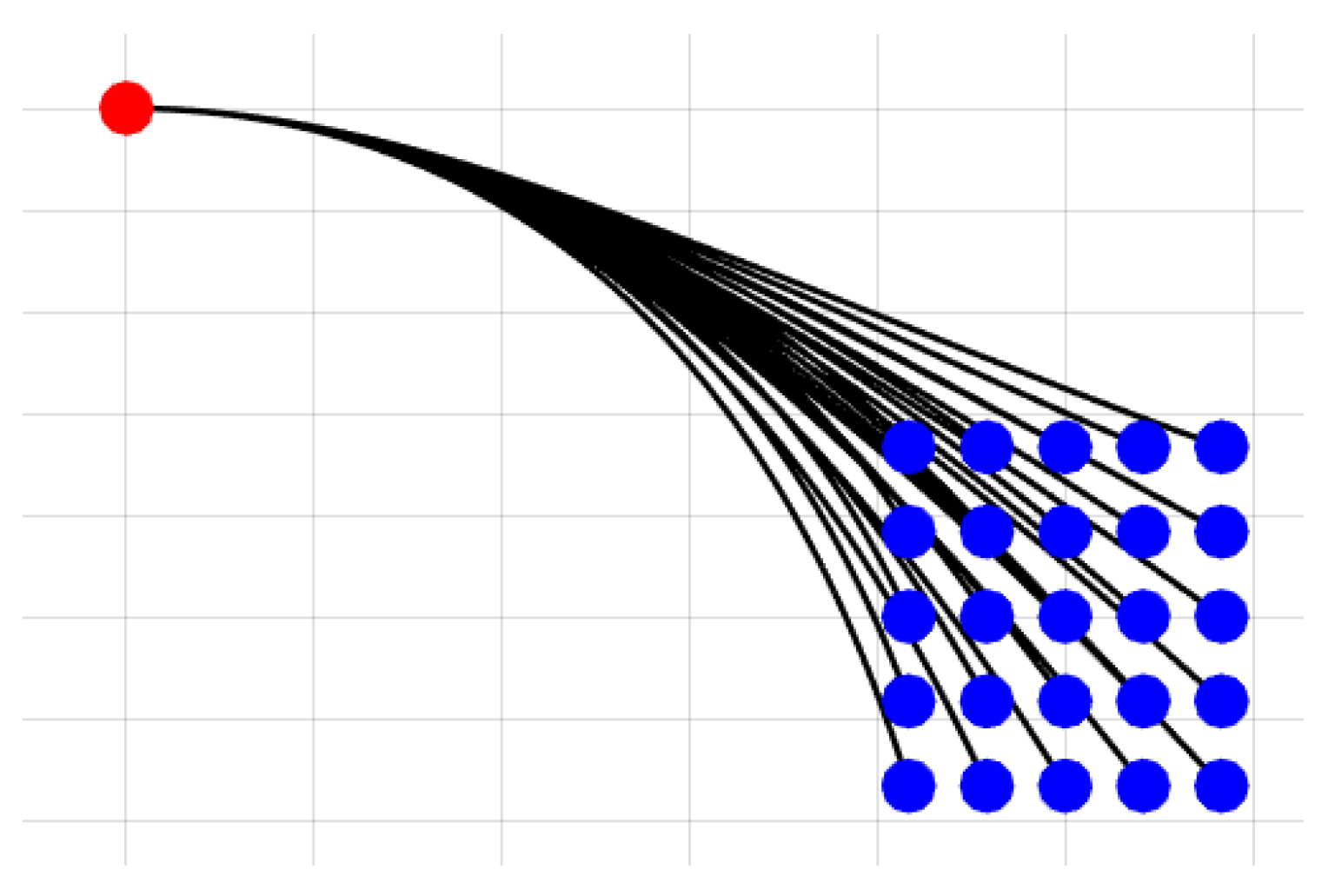
Following the procedure proposed in [8], a discretization U L = { u 1 , , u L } of the admissible control input set U = [ u m a x , u m a x ] is considered. Each control u l R 3 defines a short-duration trajectory, denoted motion primitive. To create this discretization, a discrete number of samples N s is selected along each axis within the permissible control input range [ 0 , u m a x ] . This choice of samples results in a discretization step d u = u m a x N s , which, in turn, generates a total of ( 2 N s + 1 ) 3 motion primitives [25]. Figure 3 shows an example of motion primitives generated through this approach.
The generated motion primitives are feasible with respect to control input constraints (e.g., acceleration), as they are derived from inputs within the admissible control input set. However, it is important to note that constraints regarding other state variables (e.g., velocity) and obstacle avoidance are not taken into account during the motion primitive generation phase. Each primitive must be evaluated against these constraints to ensure a trajectory that is both dynamically feasible and collision-free. This feasibility check occurs online, which is inherently time-consuming and significantly slows down real-time trajectory computation.

5.2. Graph Construction

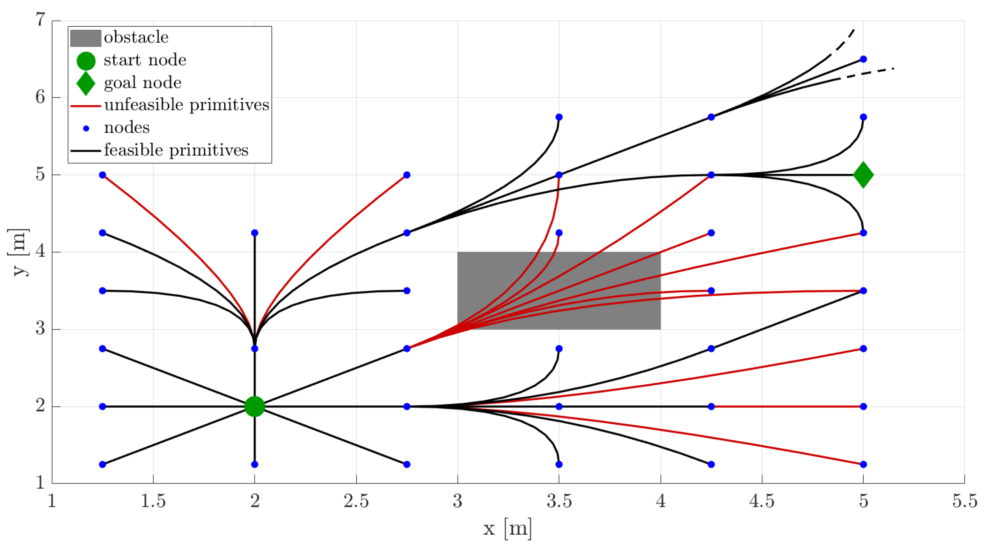
Motion primitives create a finite lattice discretization within the state space, enabling the construction of a graph representation G ( V , E ) , as illustrated in Figure 4. Here, V represents the set of states and E represents the set of edges. The states in V , depicted as blue dots in Figure 4, are generated by iteratively applying each control input u l U L for a duration τ to each initial state. This process results in ( 2 N s + 1 ) 3 distinct motion primitives. Among these, the motion primitives that are both collision-free and dynamically feasible, shown as black curves in Figure 4, form the set of edges E . Motion primitives that collide with obstacles or are dynamically unfeasible (e.g., exceed velocity limits), depicted as red curves in Figure 4, are excluded from the graph representation.

5.3. Search-Based Kinodynamic Motion Planning

By leveraging the graph representation, the motion planning problem can be reformulated as a graph-search problem, representing the discrete version of Problem (3). Based on [25], this can be done by treating the control as piecewise constant over intervals of duration τ : u ( t ) = n = 0 N 1 u n . Given an initial state x i , a goal region X g o a l , and a finite set of motion primitives, each with a duration τ > 0 , the objective is to determine the optimal sequence of control inputs u n , n = 0 , . . . , N 1 such that
min u n , x n , N n = 0 N 1 u n 2 + ρ N τ s . t . x n ( t ) = F ( t ) x i , n + G ( t ) u n , n = 0 , , N 1 , t [ 0 , τ ] x n ( t ) X , n = 0 , , N 1 , t [ 0 , τ ] u n U L , n = 0 , , N 1 x i , n + 1 = x n ( τ ) , n = 0 , , N 1 x i , 0 = x i , x i , N X g o a l .
As mentioned in Section 2.1, the position p is required to be four times differentiable, and the yaw angle ψ must be twice differentiable to fully define the state (see Appendix A for further details). Under these conditions, Equation (1) is automatically satisfied. However, lower degrees of differentiability are often utilized for computational efficiency.
The A* algorithm [24] is used to solve Problem (8). A* employs the GetSuccessors procedure outlined in Algorithm 2 to explore the state space and construct the graph. In essence, for each control action within the admissible control input set u l U L , a motion primitive is generated. This involves applying the selected control action u l to the current node v for a duration τ . Subsequently, the trajectory’s dynamic feasibility and obstacle avoidance are evaluated. If both criteria are met, the successor node v f is added to the successors list along with the cost of the primitive.
Algorithm 2 Given the current node v and the discretized control set U L , find the set of successors of v Succ(v) and their associated cost SuccCost(v)
1:
function GetSuccessors(v, U L , τ )
2:
Succ(v) ;
3:
SuccCost(v) ;
4:
for all  u l U L  do
5:
   pr ←GeneratePrimitive(v, u l ,τ);
6:
   if isDynamicallyFeasible(pr) and isCollisionFree(pr) then
7:
       v f pr( τ );
8:
      Succ(v) ← Succ(v) { v f } ;
9:
      SuccCost(v) ← SuccCost(v) { ( u l 2 + ρ ) τ } ;
10:
  end if
11:
end for
12:
return Succ(v), SuccCost(v);
13:
end function

6. Numerical Simulations

This section presents the numerical simulations performed to demonstrate the effectiveness of the two methods. Specifically, a quadrotor is tasked with navigating from an initial state located at ( x i , y i ) = ( 2 , 1 ) m to a final state positioned at ( x f , y f ) = ( 42 , 12 ) m within a 2D 45 m × 15 m virtual environment. At both the initial and final states, velocity and eventually accelerations are set to zero.
Motion primitives library: To guarantee the automatic satisfaction of the system dynamics described in Equation (1), the position p must be at least four times differentiable. Therefore, a fifth-order polynomial representation of the 2D position is considered. This ensures continuity in terms of position, velocity, acceleration, jerk, snap, and the derivative of snap along each primitive. However, to prevent the library from becoming prohibitively large, the initial and final conditions for database generation are enforced only on position, velocity, and acceleration. As a result, the planned trajectory will be continuous in position, velocity, and acceleration. The remaining state variables will be continuous along each motion primitive and will experience discontinuity at the concatenation points.
The motion primitives library is generated by solving a particular instance of Problem (6) for every combination of initial and final states, employing MATLAB’s R2024a fmincon function. Specifically, a trade-off between the integral of the jerk squared and primitive duration is minimized. Constraints are imposed on total acceleration and total jerk, set, respectively, at a m a x = 3 2 ms−2 and j m a x = 15 2 ms−3. Note that by leveraging the differential flatness property, the imposition of constraints on acceleration and jerk effectively restricts the commanded thrust and commanded angular rates to ensure adherence to the actuation constraints. This ensures that the motion primitives remain feasible and executable within the physical constraints of the platform. Additional information can be found in Appendix A.
Online motion primitives: To achieve a dynamically feasible trajectory, a fourth-order polynomial representation of position should be employed, with the snap serving as control input. However, planning in higher-dimensional spaces requires more time. Additionally, discretizing the snap is not intuitive due to its lack of direct physical meaning. Furthermore, an online feasibility check, as described in Section 5.1, must be conducted for velocity, acceleration, and jerk. This process is computationally intensive when performed online, making it inefficient. In practice, it is more effective to sample over acceleration and employ second-order polynomials for position, as done in [8]. This approach restricts the feasibility check to velocity alone, significantly reducing the online computational load. Additionally, discretizing acceleration is straightforward due to the well-understood impact of acceleration on the behavior of the system. Therefore, in this example, second-order polynomials are used to represent position. The 2D quadrotor state is defined as x ( t ) = ( x , y , v x , v y ) and acceleration a = ( a x , a y ) is used as control input. Total velocity v = v x 2 + v y 2 is constrained to be lower than 1.5 2 ms−1. Maximum acceleration along each axis is set to 3 ms−2.

6.1. Parameters Selection and State Space Discretization

This section explains how the discretization of the state space, as well as input discretization U L and the primitive duration τ , influence planning performance. Furthermore, it elaborates on their selection process tailored to the specific application at hand.
State space discretization for library computation: The discretization of the state space significantly affects planning performance, including computation time and solution optimality. The grid resolution determines the density of the graph and the computation time. A fine-resolution grid results in a denser graph, allowing for a more complete search and smoother trajectories. However, a denser graph requires more exploration to reach the goal, thus increasing computation time due to the higher number of nearby nodes to be checked. Conversely, a coarse resolution grid limits the set of candidate solutions, which can potentially result in search failures. Specifically, if the state space discretization is not fine enough, the resulting problem could become infeasible. However, for computational reasons, a coarse grid is preferable as it reduces the number of neighbor connections to be evaluated, therefore speeding up the search process.
Determining the optimal state space discretization depends on the specific application. For this specific application, the following state space discretization has been found suitable. The database is assembled starting from an initial position at ( x i , y i ) = ( 0 , 0 ) . It is based on a uniform square grid, where the final state position coordinates ( x f , y f ) [ 4 , 0 ) ( 0 , 4 ] × [ 4 , 0 ) ( 0 , 4 ] and each square cell spans one meter. These values have been selected based on the simulation environment. Given that the environment is large and filled with obstacles, it is beneficial to include both long (e.g., 4 m) and short (e.g., 1 m) motion primitives in the library. This approach allows the system to use shorter motion primitives for navigating through obstacle-dense regions to avoid collisions and longer primitives for traversing obstacle-free areas, ensuring smoother motion. Initial and final velocities ( v x i , v y i , v x f , v y f ) and initial and final accelerations ( a x i , a y i , a x f , a y f ) are each selected from a set of three values to prevent the library from becoming prohibitively large. Specifically, initial and final velocities are selected from { 1.5 , 0 , 1.5 } ms−1, and initial and final accelerations are chosen from { 3 , 0 , 3 } ms−2.
Control input discretization and motion primitive duration for online motion primitives computation: The motion primitives duration τ and the control input discretization U L have a significant effect on the planning performance, including computation time and optimality of the solution. The primitives duration τ determines the density of the graph and computation time. A small τ results in a denser graph, requiring more exploration to reach the goal, therefore increasing computation time. Conversely, large τ reduces the space of candidate solutions, potentially leading to search failures. Specifically, if the discretization of the control input U L is not fine enough, the resulting problem could become infeasible (i.e., the set of candidate solutions could be empty). Moreover, since the goal is to optimize the duration of the overall trajectory, the duration of the primitives τ imposes a lower bound on the optimality of the solution. As the duration of the motion primitives decreases, so does the cost of the optimal trajectory. However, for computational reasons, a longer duration is preferable. The control space discretization U L also influences the density of the graph and computation time: finer discretization yields a slower but more complete search and smoother trajectories, while coarser discretization produces the opposite effect. Moreover, finer control space discretization U L significantly increases computation time, making the approach impractical in practice.
The optimal combination of control input discretization and primitive duration depends on the specific application. For this specific application, the following values have proven to be suitable. To ensure a balance between search completeness and computational efficiency, the set of control inputs is discretized into nine options within the allowable range of ( u x , u y ) = ( a x , a y ) [ 3 , 3 ] ms−2 and the primitive duration is set at τ = 0.5 s.

6.2. Simulations Results

This section presents the results of the numerical simulations.
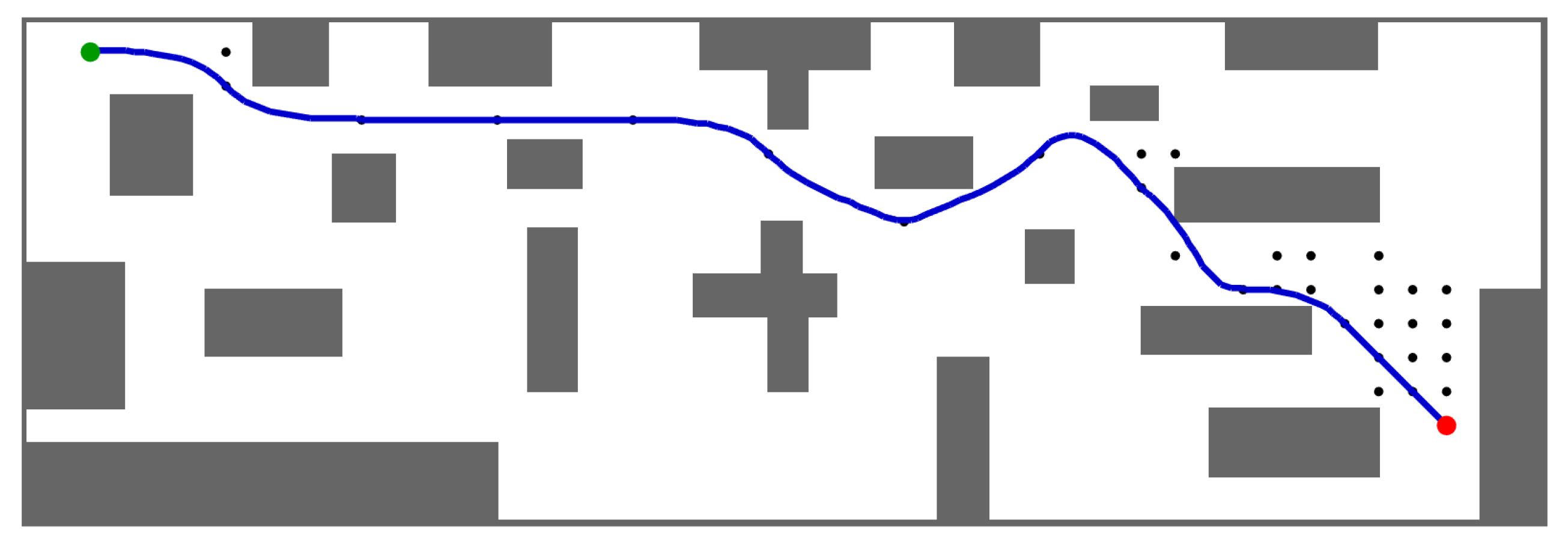
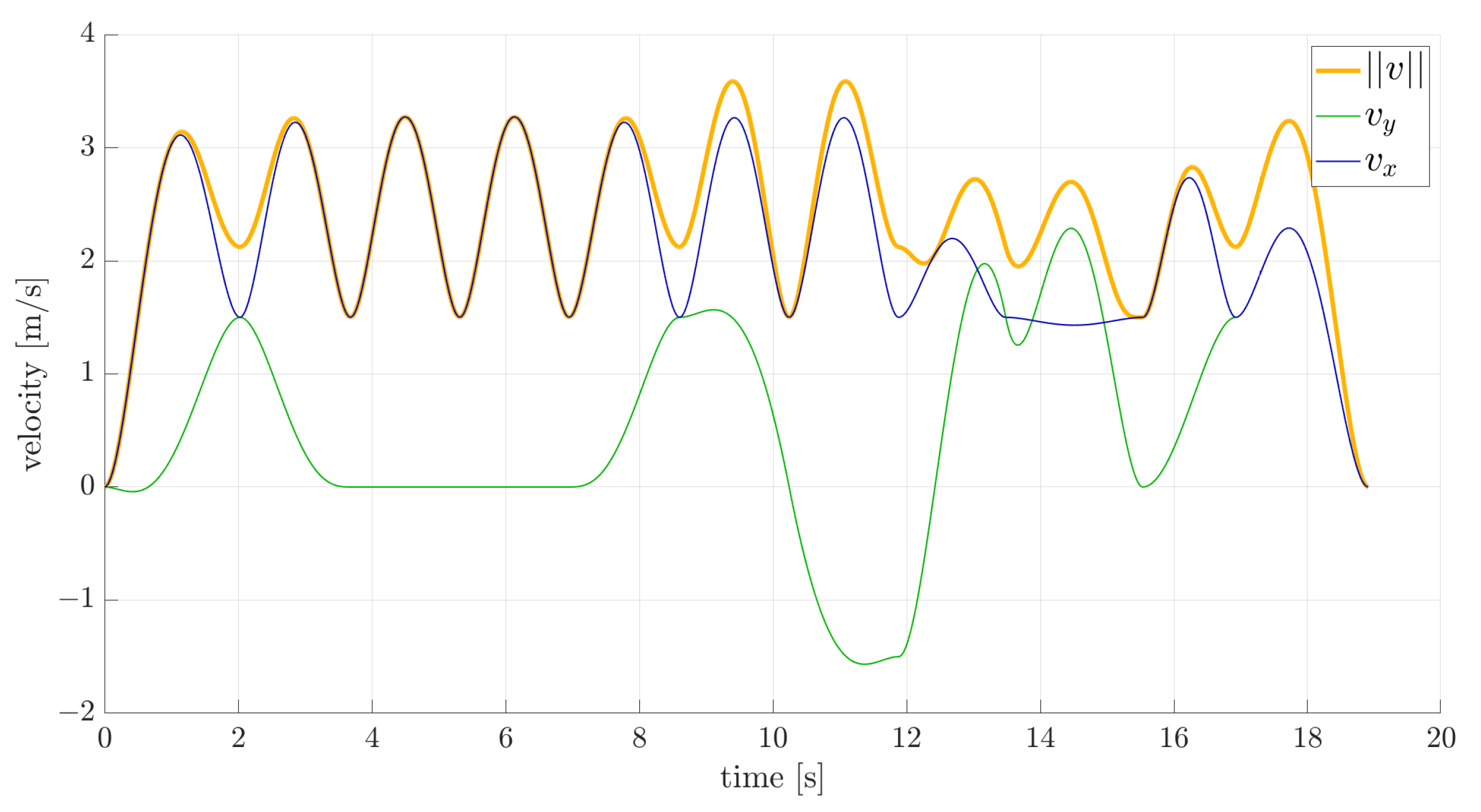
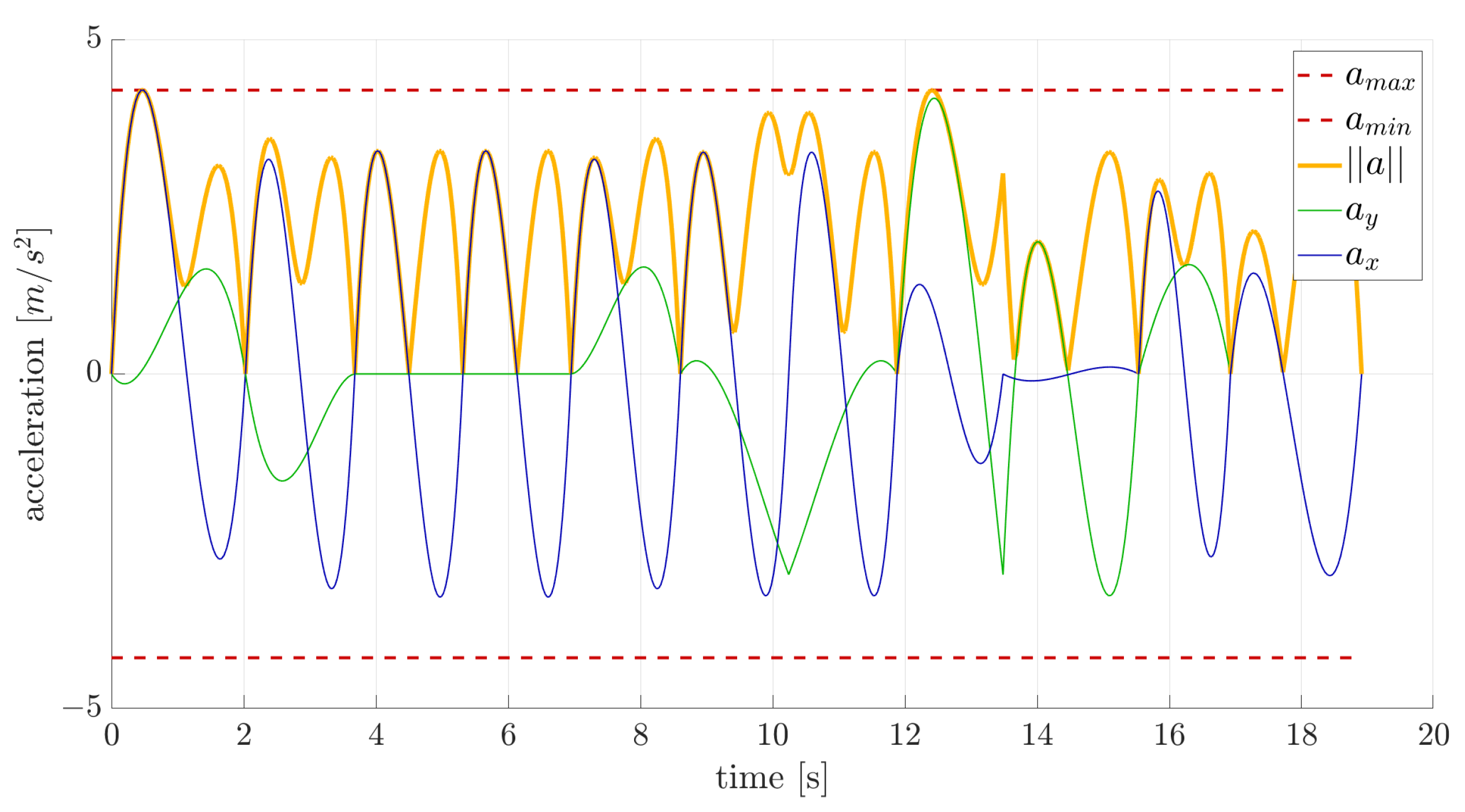
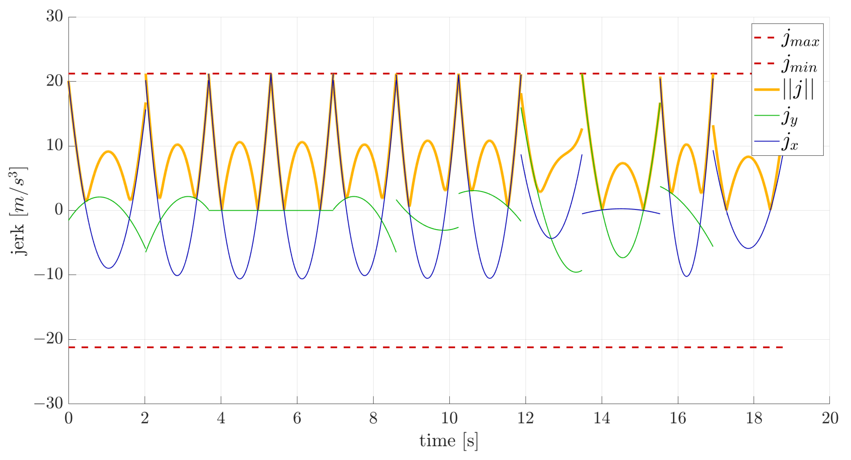
Planning with motion primitives library: Figure 5 shows the optimal collision-free trajectory guiding the vehicle from the initial state (green dot) to the goal state (red dot). Figure 6, Figure 7 and Figure 8 depict the velocity, acceleration, and actuation profiles. These figures demonstrate the efficacy of this approach in generating collision-free and dynamically feasible trajectories. Observing the velocity profile in Figure 6, it is evident that rather than experiencing a gradual and continuous increase in velocity, sudden changes in acceleration occur. This issue arises from constraining velocity and acceleration at each node to match one of the values in the database precisely. To obtain a smoother trajectory, a finer state space discretization is required.
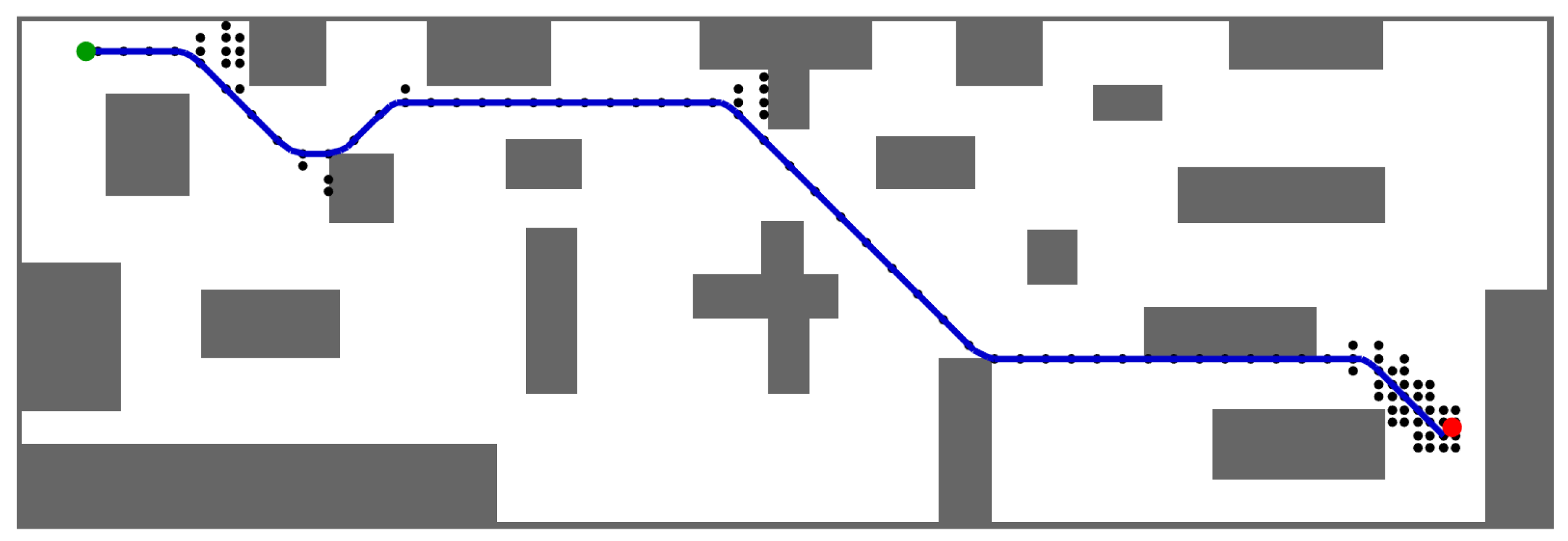
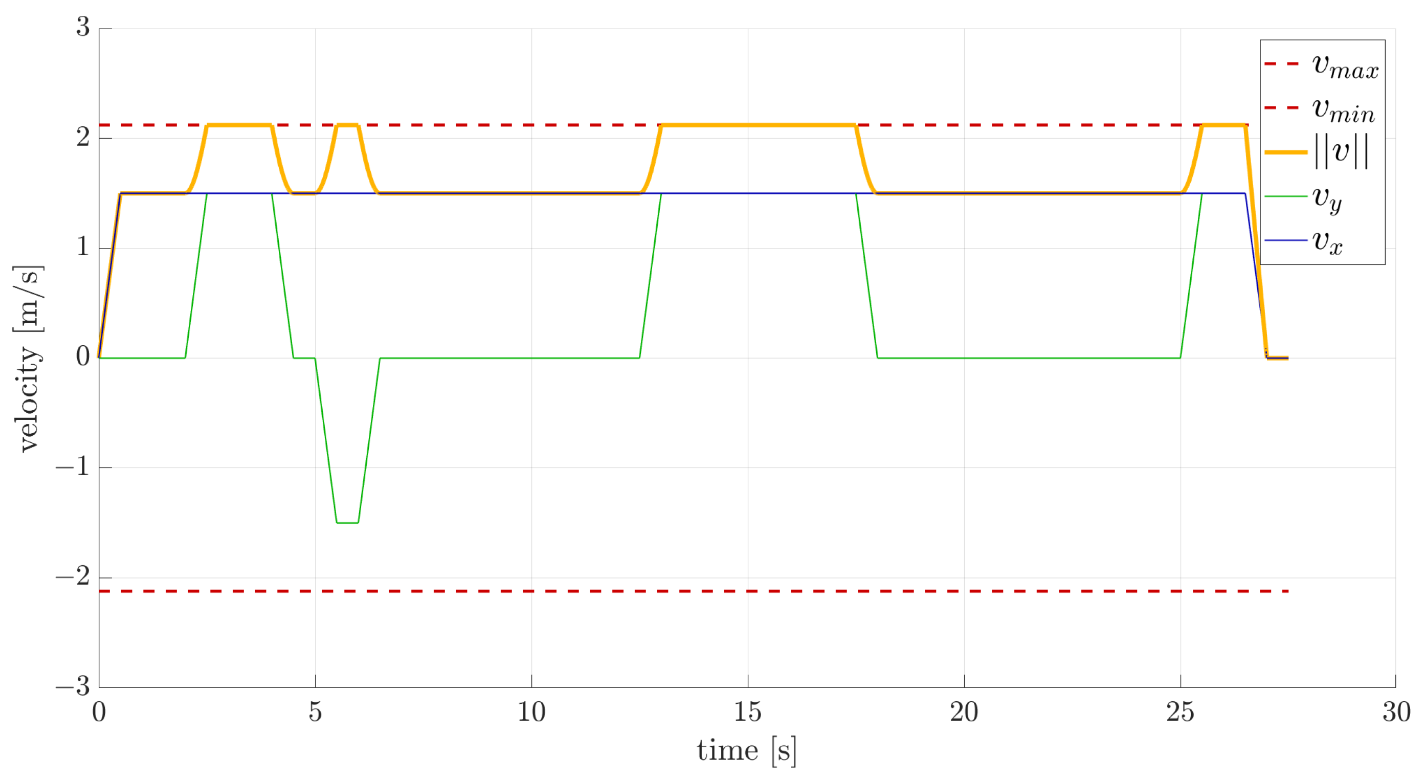
Planning with online motion primitives: Figure 9 shows the optimal collision-free trajectory guiding the vehicle from the start state (green dot) to the target state (red dot). Figure 10 and Figure 11 show the velocity profile and the actuation (acceleration) profile for the optimal trajectory, demonstrating adherence to velocity constraints.

7. Experimental Results

This section presents the experimental tests performed to demonstrate the effectiveness of the two methods on a real quadrotor.

7.1. Experimental Set-Up

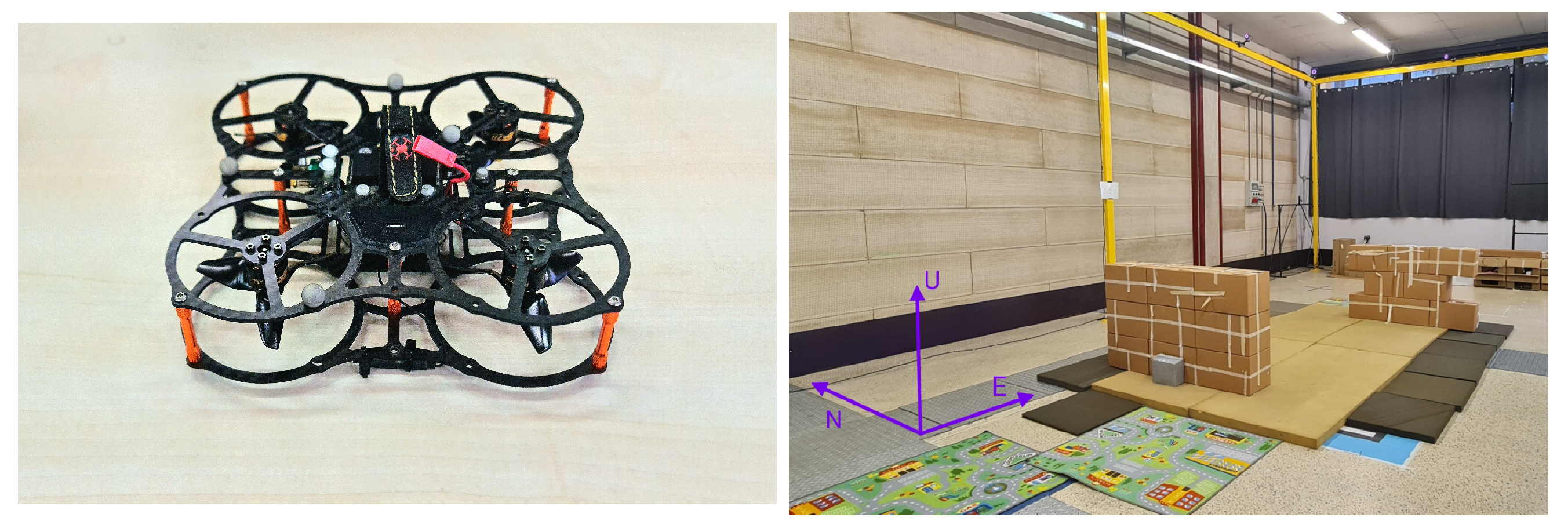
Flight tests take place within the indoor Flying Arena for Rotorcraft Technologies (FlyART) at Politecnico di Milano, equipped with a Motion Capture system (Mo-Cap) comprising 12 cameras (Figure 12). The UAV employed for these tests is an ANT-X fixed-pitch quadrotor [26] (Figure 12). The Mo-Cap system detects markers mounted to the UAV and collects measurements, which are then transmitted to a ground control station. These measurements, along with the trajectory to be followed defined by specific waypoints, are forwarded to the drone at frequencies of 100 Hz and 20 Hz, respectively.
Note that the maximum velocity v m a x and acceleration a m a x constraints generally come from the dynamics of the system in question, such as the thrust-to-weight ratio. The platform utilized in the experimental tests has a thrust-to-weight ratio of approximately 2.5 . However, it is often necessary to impose constraints on maximum velocity and acceleration due to spatial limitations and safety concerns. As a result, lower values are selected as constraints for the experimental tests.
The control system employed follows a set-up similar to the PX4 autopilot, employing a cascaded controller structure. Specifically, it features a double cascade arrangement using P/PID controllers for position and attitude control. Moreover, this set-up involves modifications to the PX4 autopilot, incorporating position, velocity, and acceleration feedforwards. For more details, please refer to [27,28].
The motion planning computations are executed in MATLAB on a personal computer equipped with an Intel Core i7 processor running at 2.30 GHz and 16 GB RAM. Future work will involve converting all components of the online phase to C++ for execution on an embedded processor within the quadrotor.
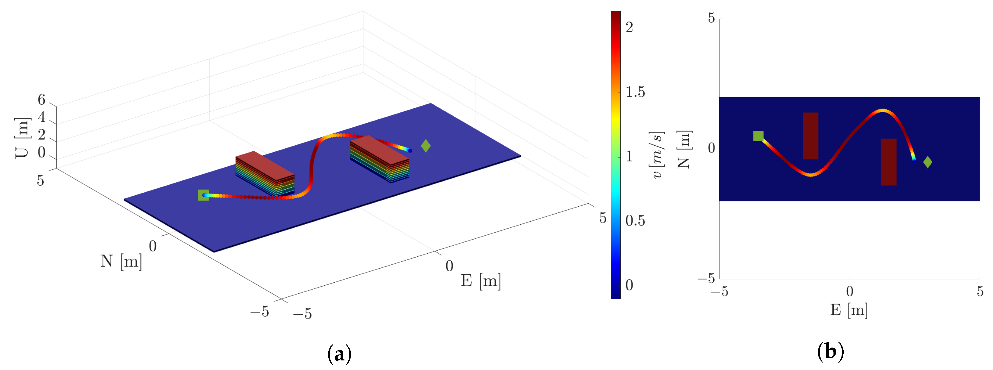
The UAV operates in a 10 m × 4 m environment featuring two 0.4 m × 1.5 m obstacles. The starting position is set at p i = ( 3.5 , 0.5 , 1 ) m, and the goal region is a square with a side length of 0.5 m, centered at p f = ( 3 , 0.5 , 1 ) m. Velocity and acceleration are zero at both the initial and final positions.

7.2. Experiment: Planning with Motion Primitives Library

A fifth-order polynomial representation of the 2D position is employed for this experiment. The database of motion primitives is computed by solving a particular instance of Problem (6) for every combination of boundary conditions. The database is assembled starting from an initial position at ( x i , y i ) = ( 0 , 0 ) . It is based on a uniform square grid, where the final state position coordinates ( x f , y f ) [ 2 , 0 ) ( 0 , 2 ] × [ 2 , 0 ) ( 0 , 2 ] and each square cell spans half a meter. Initial and final velocities are selected from { 1.5 , 0 , 1.5 } ms−1, and initial and final accelerations are chosen from { 4.5 , 0 , 4.5 } ms−2. Total velocity, acceleration, and jerk limits are set at v m a x = 1.5 2 ms−1, a m a x = 4.5 2 ms−2 and j m a x = 15 2 ms−3. In this experiment, a constraint on the maximum speed is added due to spatial limitations and safety concerns. Refer to Section 6.1 for insights on selecting the state space discretization.
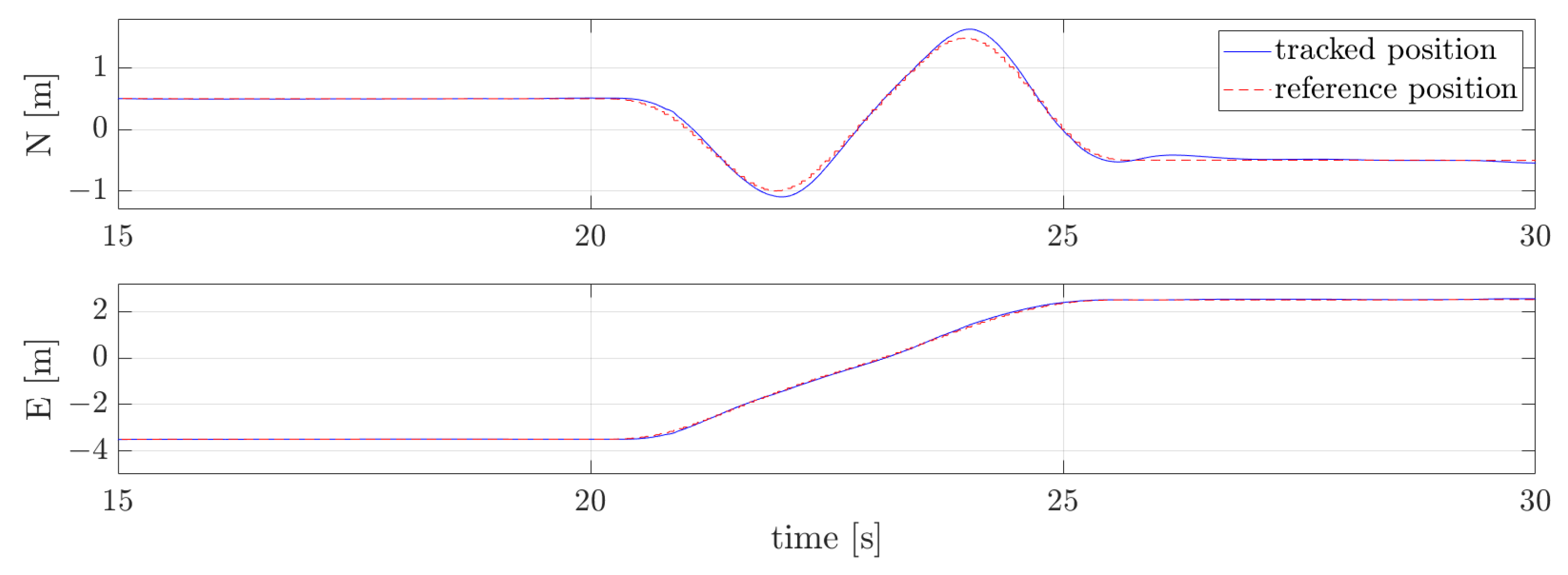
Figure 13 shows the obstacle-free planned trajectory. Figure 14 and Figure 15 depict the position and velocity profiles with their references, demonstrating precise tracking. References represent the desired positions and velocities of the planned trajectory. Specifically, they are the target values for each motion primitive that composes the planned trajectory. These target values are fed to the control system to ensure tracking and execution of the planned path.

7.3. Experiment: Planning with Online Motion Primitives

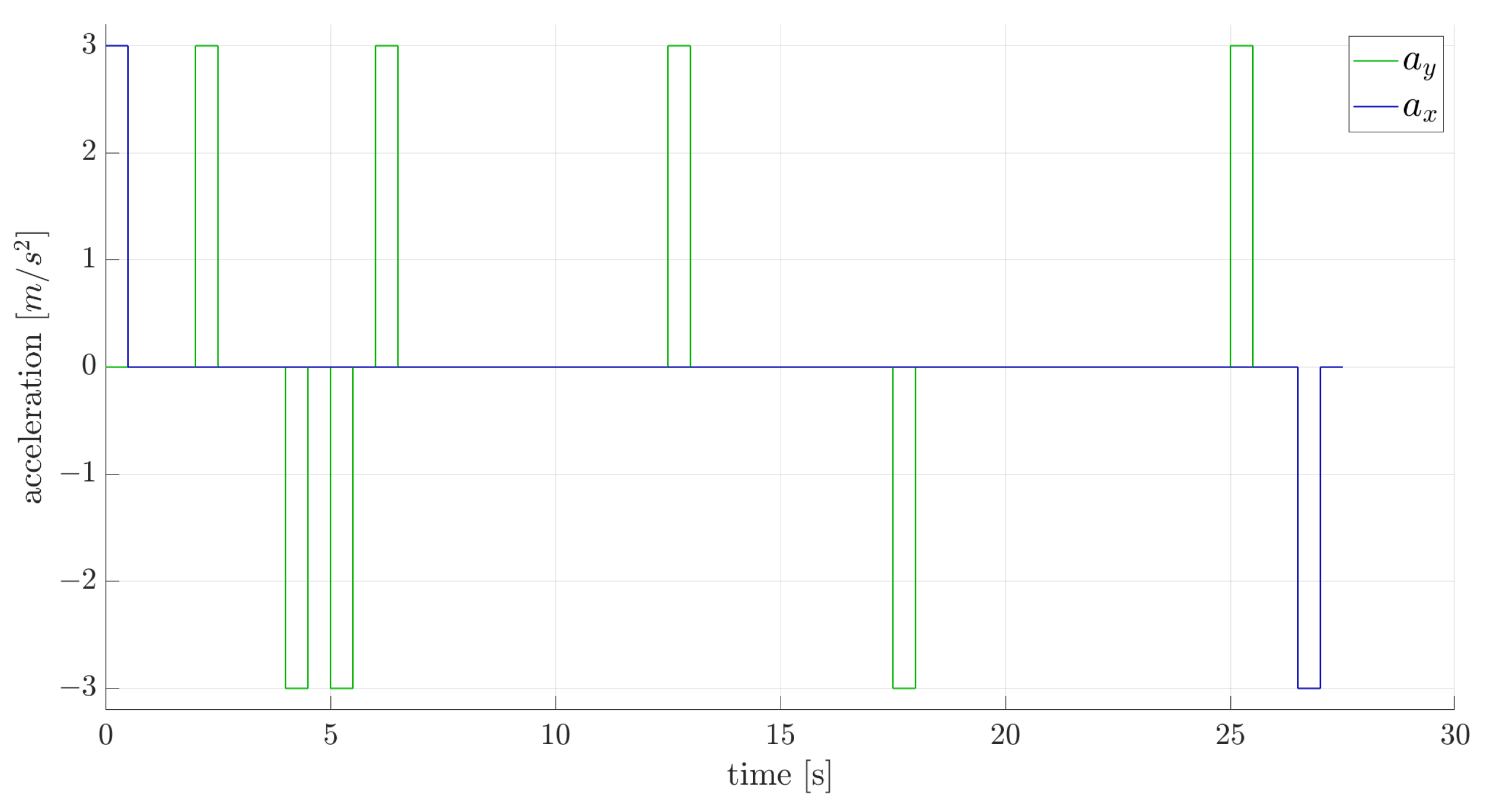
In this experiment, second-order polynomials are used to represent position. The 2D quadrotor state is defined as x ( t ) = ( x , y , v x , v y ) and acceleration a = ( a x , a y ) is used as control input. The set of control inputs is discretized with nine options within the allowable range of ( u x , u y ) = ( a x , a y ) [ 3 , 3 ] ms−2 and the duration of the primitives is set to a fixed value of τ = 0.5 s. Total velocity v = v x 2 + v y 2 is constrained to be lower than 1.5 2 ms−1. Refer to Section 6.1 for insights on selecting the input discretization and primitive duration.
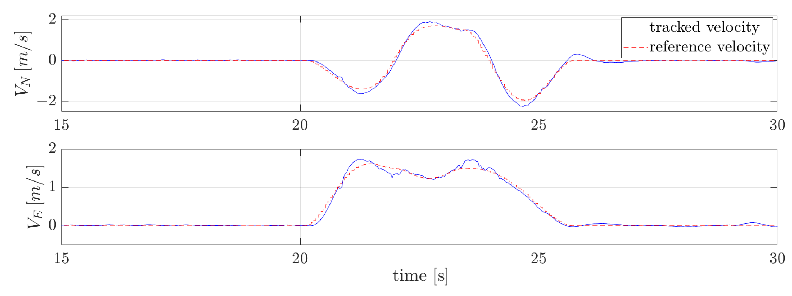
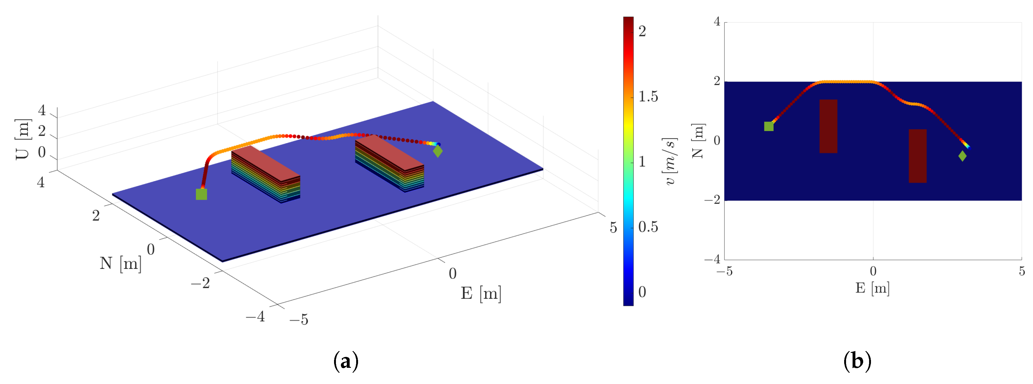
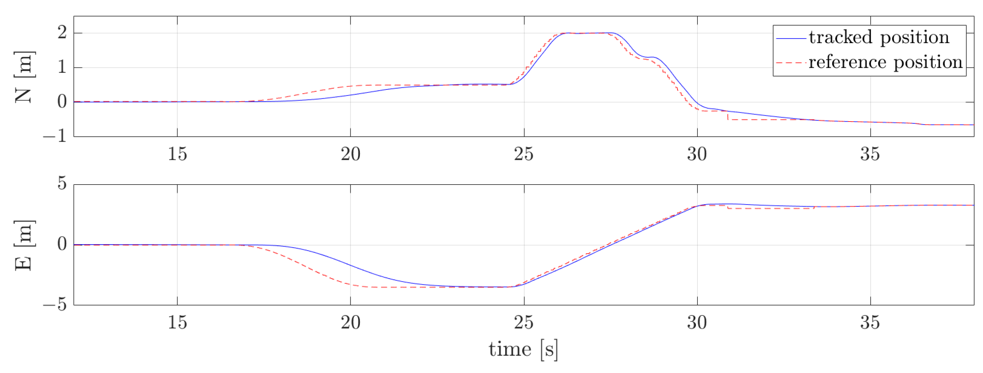
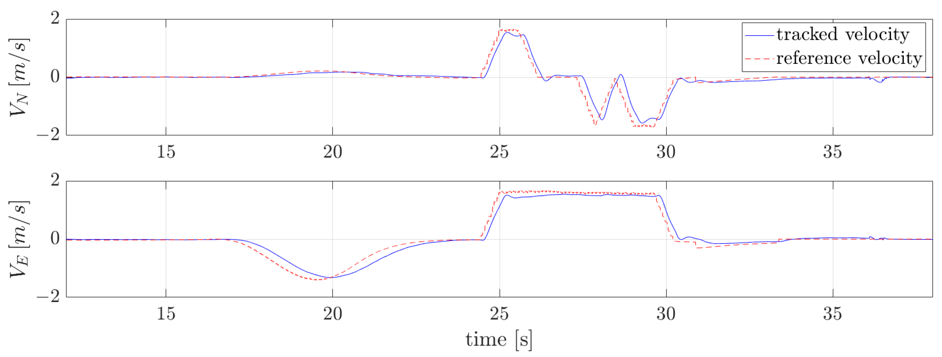
Figure 16 depicts the planned obstacle-free trajectory. Figure 17 and Figure 18 show the tracked position and velocity profiles alongside their corresponding references, demonstrating good tracking.

8. Discussion

This section delves into a comparative analysis of the two approaches, each offering distinct advantages. The selection of the appropriate method depends on the specific characteristics of the system at hand and its performance requirements. For a concise overview, the key features of both methods are summarized in Table 1 and discussed in the following sections.

8.1. Adaptability to Complex Systems

The planning with online motion primitives method is advantageous when a simplified representation of the system accurately captures its dynamics. This approach is particularly useful in scenarios where moderate performance and tracking are acceptable, making a simplified model adequate to satisfy these requirements. However, its applicability to more complex systems is limited. On the other hand, the planning with motion primitives library method is the preferred choice when a simplified representation of the system fails to meet performance requirements, necessitating a more complex model. In fact, this method extends its applicability beyond differentially flat quadrotor systems to encompass a wide range of complex systems, including VTOL and fixed-wing aircraft. Its versatility is attributed to its capacity to shift the computational demands of trajectory generation to an offline phase, therefore ensuring precise solutions without compromising efficiency. Furthermore, this method is advantageous in scenarios requiring aggressive and agile maneuvers, where precise tracking and the full utilization of the system’s capabilities are essential.

8.2. Motion Primitives Duration

In the planning with online motion primitives method, all the motion primitives have the same duration, denoted as τ , which is usually set sufficiently large for computational reasons. However, this hinders the overall objective of achieving a minimum-time trajectory. In contrast, the planning with motion primitives library method employs minimum-time primitives generated by solving a TPBVP, aligning more closely with the objective of achieving a minimum-time trajectory.

8.3. Motion Primitives Feasibility Check

The planning with online motion primitives method generates motion primitives through control input discretization and forward propagation of the dynamic equations of a simplified model. Consequently, the resulting primitives are feasible with respect to control inputs (e.g., acceleration) but do not inherently incorporate velocity constraints, necessitating a subsequent feasibility check. This additional step involves further computations and significantly slows down the online trajectory computation. In contrast, the planning with motion primitives library method directly incorporates velocity, acceleration, and other constraints into its library, eliminating the need for a subsequent feasibility check and accelerating online trajectory computation.

8.4. Further Considerations

In a known environment, geometric considerations on the environment itself (e.g., environment dimensions, characteristics distances between obstacles) easily translate into grid selection. On the contrary, the tuning process for the control input set and the duration of primitives τ is more challenging, especially for complex systems.

9. Conclusions

This work addresses trajectory planning for UAVs in the presence of obstacles by introducing a library of motion primitives tailored for quadrotors. The versatility of this approach lies in its ability to shift the computational demands of trajectory generation to the offline phase of database construction. To further enhance computational tractability, continuity between consecutive motion primitives is enforced only on a subset of state variables (position, velocity, and acceleration). This method has proven effective in maintaining computational efficiency while ensuring accurate trajectory planning and proves promising for applications to more complex systems, including VTOL and fixed-wing aircraft.
The proposed method is compared with a state-of-the-art quadrotor-tailored search-based planner, which generates motion primitives online by discretizing control inputs and propagating the dynamic equations of a simplified model forward. However, this state-of-the-art approach is computationally efficient only for simple systems, such as single or double integrators. Conversely, the proposed library-based method enables efficient motion planning for arbitrary systems.
Notably, both methodologies demonstrate the ability to generate resolution-complete, collision-free, resolution-optimal, and dynamically feasible trajectories, as demonstrated by numerical and experimental results. Furthermore, a comparison of the two approaches highlights their respective strengths and weaknesses.
Future research will focus on addressing motion planning in unknown and dynamic environments. This involves vision-based dynamic replanning using real-time data to navigate and avoid newly detected obstacles. Furthermore, upcoming studies will concentrate on developing motion primitive libraries for the identified model of the quadrotor. Additionally, efforts will be directed toward mitigating the discontinuity of the state variables at the nodes. Although enforcing continuity during the library construction phase presents memory challenges, a potential solution involves generating a trajectory that guarantees only position and velocity continuity at the nodes. This trajectory will serve as a high-quality initial guess for an online trajectory-generation algorithm, with continuity in other states achieved in a receding horizon fashion.
Author Contributions

Conceptualization, M.M., D.I. and R.R.; Methodology, M.M. and R.R.; Software, M.M.; Validation, M.M.; Investigation, M.M. and R.R.; Writing—Original Draft Preparation, M.M.; Writing—Review and Editing, M.M., R.R. and D.I.; Visualization, M.M.; Supervision, D.I.; Project Administration, D.I. All authors have read and agreed to the published version of the manuscript.

Funding

This study was carried out within the Agritech National Research Center and received funding from the European Union Next-GenerationEU (PIANO NAZIONALE DI RIPRESA E RESILIENZA (PNRR)—MISSIONE 4 COMPONENTE 2, INVESTIMENTO 1.4—D.D. 1032 17/06/2022, CN00000022). This manuscript reflects only the authors’ views and opinions, neither the European Union nor the European Commission can be considered responsible for them.

Data Availability Statement

The code supporting the conclusions of this article will be made available by the authors on request.

Acknowledgments

The authors express their gratitude to Giovanni Gozzini for his invaluable collaboration, which enabled the execution of the experimental tests.

Conflicts of Interest

The authors declare no conflicts of interest.

Appendix A. Differential Flatness

A system can be defined differentially flat if a subset of the output, called flat output, exists, such that the state and input can be defined as functions of the flat output and a finite number of its derivatives. More precisely, a nonlinear system
x ˙ = f ( x , u ) , x R n , u R m
is differentially flat if and only if there exists a flat output σ = ( σ 1 , , σ m ) depending on the state and on a finite number of the input derivatives
σ = h ( x , u , u ˙ , , u ( r ) ) , σ R m
such that the state x and the input u can be defined as smooth functions of this flat output and its derivatives as follows:
x = h x ( σ , σ ˙ , σ ¨ , , σ ( q ) )
u = h y ( σ , σ ˙ , σ ¨ , , σ ( q ) ) ,
where h x and h y are smooth functions and q is some finite number.
As demonstrated in [21], the quadrotor with the four inputs is a flat system characterized by the flat output
σ = ( p , ψ ) ,
where p = ( x , y , z ) are the coordinates of the center of mass and ψ is the yaw angle. Consequently, the state of the quadrotor x = ( p , v , R , ω ) and its control input u = ( t c , τ c ) can be expressed as algebraic functions of the four selected flat outputs and a finite number of their derivatives.
In particular, the translational components of the state (position p, velocity v, acceleration a, jerk j, and snap s) can easily be derived from the first three elements of σ , σ ˙ , σ ¨ , σ , and σ , respectively. Additionally, the orientation R can be written as an algebraic function of the acceleration a, which involves the first three components of the second derivative of the flat output σ ¨ , as well as the yaw angle ψ
R = f R ( a , ψ ) .
Furthermore, the thrust input t c is a function of the acceleration a
t c = f t c ( a ) .
The body rates ω can be written as functions of the acceleration a, jerk j, yaw angle ψ and its first derivative ψ ˙
ω = f ω ( a , j , ψ , ψ ˙ ) .
Finally, the angular accelerations (torque inputs) ω ˙ can be expressed as functions of the acceleration a, jerk j, snap s, yaw angle ψ and its first ψ ˙ and second ψ ¨ derivatives.
ω ˙ = f ω ˙ ( a , j , s , ψ , ψ ˙ , ψ ¨ ) .
The complete expressions of the previous relations and their proof can be found in [21] and can be derived by neglecting the drag component.
The expression of the state variables x and control inputs u as functions of the flat outputs σ , and their derivatives guarantees the automatic satisfaction of the system dynamics detailed in Equation (1). This is true as long as the flat outputs and their derivatives adhere to specific smoothness conditions. Specifically, the position p must be at least four times differentiable, and the yaw angle ψ must be at least twice differentiable to retrieve the complete state of the quadrotor system, as shown in Equations (A6)–(A9), which show that the original states x and control inputs u of the quadrotor depend on the snap s (the fourth derivative of the position) and ψ ¨ (the second derivative of the yaw).

References

  1. Dharmadhikari, M.; Dang, T.; Solanka, L.; Loje, J.; Nguyen, H.; Khedekar, N.; Alexis, K. Motion Primitives-based Path Planning for Fast and Agile Exploration using Aerial Robots. In Proceedings of the 2020 IEEE International Conference on Robotics and Automation (ICRA), Paris, France, 31 May–31 August 2020; pp. 179–185. [Google Scholar] [CrossRef]
  2. Frazzoli, E.; Dahleh, M.A.; Feron, E. Robust hybrid control for autonomous vehicle motion Planning. In Proceedings of the the 39th IEEE Conference on Decision and Control, Sydney, Australia, 12–15 December 2000; pp. 821–826. [Google Scholar] [CrossRef]
  3. Frazzoli, E.; Dahleh, M.A.; Feron, E. Real-time motion planning for agile autonomous vehicles. J. Guid. Control Dyn. 2002, 25, 116–129. [Google Scholar] [CrossRef]
  4. Bottasso, C.L.; Leonello, D.; Savini, B. Path planning for autonomous vehicles by trajectory smoothing using motion primitives. IEEE Trans. Control Syst. Technol. 2008, 16, 1152–1168. [Google Scholar] [CrossRef]
  5. Richter, C.; Bry, A.; Roy, N. Polynomial Trajectory Planning for Aggressive Quadrotor Flight in Dense Indoor Environments. In Robotics Research: The 16th International Symposium ISRR; Springer International Publishing: Berlin/Heidelberg, Germany, 2016; pp. 649–666. [Google Scholar] [CrossRef]
  6. Mueller, M.W.; Hehn, M.; D’Andrea, R. A computationally efficient algorithm for state-to-state quadrocopter trajectory generation and feasibility verification. In Proceedings of the 2013 IEEE/RSJ International Conference on Intelligent Robots and Systems (IROS), Tokyo, Japan, 3–7 November 2013; pp. 3480–3486. [Google Scholar] [CrossRef]
  7. Mueller, M.W.; Hehn, M.; D’Andrea, R. A Computationally Efficient Motion Primitive for Quadrocopter Trajectory Generation. IEEE Trans. Robot. 2015, 6, 1294–1310. [Google Scholar] [CrossRef]
  8. Liu, S.; Atanasov, N.; Mohta, K.; Kumar, V. Search-based motion planning for quadrotors using linear quadratic minimum time control. In Proceedings of the 2017 IEEE/RSJ International Conference on Intelligent Robots and Systems (IROS), Vancouver, BC, Canada, 24–28 September 2017; pp. 2872–2879. [Google Scholar] [CrossRef]
  9. Liu, S.; Atanasov, N.; Mohta, K.; Kumar, V. Search-Based Motion Planning for Aggressive Flight in SE(3). IEEE Robot. Autom. Lett. 2018, 3, 2439–2446. [Google Scholar] [CrossRef]
  10. Mellinger, D.; Kumar, V. Minimum snap trajectory generation and control for quadrotors. In Proceedings of the 2011 IEEE International Conference on Robotics and Automation, Shanghai, China, 9–13 May 2011; pp. 2520–2525. [Google Scholar] [CrossRef]
  11. Howell, T.A.; Jackson, B.E.; Manchester, Z. ALTRO: A Fast Solver for Constrained Trajectory Optimization. In Proceedings of the 2019 IEEE/RSJ International Conference on Intelligent Robots and Systems (IROS), Macau, China, 3–8 November 2019; pp. 7674–7679. [Google Scholar] [CrossRef]
  12. Lindqvist, B.; Mansouri, S.S.; Agha-mohammadi, A.; Nikolakopoulos, G. Nonlinear MPC for Collision Avoidance and Control of UAVs With Dynamic Obstacles. IEEE Robot. Autom. Lett. 2020, 5, 6001–6008. [Google Scholar] [CrossRef]
  13. Schulman, J.; Duan, Y.; Ho, J.; Lee, A.; Awwal, I.; Bradlow, H.; Pan, J.; Patil, S.; Goldberg, K.; Abbeel, P. Motion planning with sequential convex optimization and convex collision checking. Int. J. Robot. Res. 2014, 33, 1251–1270. [Google Scholar] [CrossRef]
  14. Bonalli, R.; Cauligi, A.; Bylard, A.; Pavone, M. GuSTO: Guaranteed Sequential Trajectory optimization via Sequential Convex Programming. In Proceedings of the 2019 International Conference on Robotics and Automation (ICRA), Montreal, QC, Canada, 20–24 May 2019; pp. 6741–6747. [Google Scholar] [CrossRef]
  15. Richards, A.; How, J.P. Aircraft trajectory planning with collision avoidance using mixed integer linear programming. In Proceedings of the 2002 American Control Conference (IEEE Cat. No.CH37301), Anchorage, AK, USA, 8–10 May 2002; Volume 3, pp. 1936–1941. [Google Scholar] [CrossRef]
  16. Mellinger, D.; Kushleyev, A.; Kumar, V. Mixed-integer quadratic program trajectory generation for heterogeneous quadrotor teams. In Proceedings of the 2012 IEEE International Conference on Robotics and Automation (ICRA), Saint Paul, MN, USA, 14–18 May 2012; pp. 477–483. [Google Scholar] [CrossRef]
  17. Deits, R.; Tedrake, R. Efficient mixed-integer planning for UAVs in cluttered environments. In Proceedings of the 2015 IEEE International Conference on Robotics and Automation (ICRA), Seattle, WA, USA, 26–30 May 2015; pp. 42–49. [Google Scholar] [CrossRef]
  18. Sakcak, B.; Bascetta, L.; Ferretti, G.; Prandini, M. Sampling-based optimal kinodynamic planning with motion primitives. Auton. Robot 2019, 43, 1715–1732. [Google Scholar] [CrossRef]
  19. Invernizzi, D.; Lovera, M.; Zaccarian, L. Geometric trajectory tracking with attitude planner for vectored-thrust VTOL UAVs. In Proceedings of the 2018 Annual American Control Conference (ACC), Milwaukee, WI, USA, 27–29 June 2018; pp. 3609–3614. [Google Scholar] [CrossRef]
  20. Aguilar-Ibáñez, C.; Sira-Ramírez, H.; Suárez-Castañón, M.S.; Martínez-Navarro, E.; Moreno-Armendariz, M.A. The trajectory tracking problem for an unmanned four-rotor system: Flatness-based approach. Int. J. Control 2012, 85, 69–77. [Google Scholar] [CrossRef]
  21. Faessler, M.; Franchi, A.; Scaramuzza, D. Differential Flatness of Quadrotor Dynamics Subject to Rotor Drag for Accurate Tracking of High-Speed Trajectories. IEEE Robot. Autom. Lett. 2018, 3, 620–626. [Google Scholar] [CrossRef]
  22. Mettler, B.; Kong, Z.; Li, B.; Andersh, J. Systems view on spatial planning and perception based on invariants in agent-environment dynamics. Front. Neurosci. 2015, 8, 107432. [Google Scholar] [CrossRef] [PubMed]
  23. Ross, A.E.; Pavone, M. A real-time framework for kinodynamic planning in dynamic environments with application to quadrotor obstacle avoidance. Rob. Auton. Syst. 2019, 115, 174–193. [Google Scholar] [CrossRef]
  24. Pearl, J. Heuristics: Intelligent Search Strategies for Computer Problem Solving; Addison-Wesley Longman Publishing Co., Inc.: Albany, NY, USA, 1984. [Google Scholar]
  25. Liu, S. Motion Planning for Micro Aerial Vehicles. Ph.D. Dissertation, University of Pennsylvania, Philadelphia, PA, USA, 2018. [Google Scholar]
  26. ANT-X Website. Available online: https://antx.it/ (accessed on 26 April 2024).
  27. PX4 Guide Website. Available online: https://docs.px4.io/main/en/flight_stack/controller_diagrams.html (accessed on 29 April 2024).
  28. ANT-X SLXtoPX4 Documentation Websiete. Available online: https://ant-x.gitlab.io/documentation_dronelab/_chapters/slxtopx4/demo.html (accessed on 29 April 2024).
Figure 1. Example of planar motion primitives library for quadrotor using third-order polynomials for 2D position ( x , y ) with constraints ( v x , v y ) [ 1 , 1 ] m s 1 and ( u x , u y ) = ( a x , a y ) [ 3 , 3 ] ms−2. Red dot: initial steady state ( x i = y i = v x i = v y i = 0 ). Blue dots: final states. Black lines: reference trajectories for various final velocities. Pink lines: trajectories obtained by mirroring the reference ones.
Drones 08 00256 g001
Figure 2. Steps involved in the geometric translation. (a) First, translation is performed on initial and final states ( v i , v f ) . (b) New states ( v ^ i , v ^ f ) with the initial state v ^ i placed at the origin of the library. (c) Inverse translation to restore the trajectory connecting the original states ( v i , v f ) .
Drones 08 00256 g002
Figure 3. 2D motion primitives for a jerk-controlled system from an initial state (red dot) to different final states (blue dots).
Drones 08 00256 g003
Figure 4. Graph G ( V , E ) generated from a starting point (green circle) located at coordinates ( x i , y i ) = ( 2 , 2 ) to a goal point (green diamond) positioned at coordinates ( x f , y f ) = ( 5 , 5 ) . Blue dots: a set of nodes V . Black curves: a set of edges E (feasible motion primitives). Red curves: unfeasible motion primitives.
Drones 08 00256 g004
Figure 5. Simulation employing the planning with motion primitives library method. Green dot: initial position. Red dot: final positions. Blue curve: optimal trajectory. Black dots: expanded states.
Drones 08 00256 g005
Figure 6. Velocity profile for the optimal trajectory in Figure 5.
Drones 08 00256 g006
Figure 7. Acceleration profile for the optimal trajectory in Figure 5. Red lines: acceleration limits.
Drones 08 00256 g007
Figure 8. Jerk profile for the optimal trajectory in Figure 5. Red lines: jerk limits.
Drones 08 00256 g008
Figure 9. Simulation employing the planning with online motion primitives method. Green dot: initial position. Red dot: final position. Blue curve: optimal trajectory. Black dots: expanded nodes.
Drones 08 00256 g009
Figure 10. Velocity profile for the optimal trajectory in Figure 9. Red lines: velocity limits.
Drones 08 00256 g010
Figure 11. Actuation (acceleration) profile for the optimal trajectory in Figure 9.
Drones 08 00256 g011
Figure 12. ANT-X quadrotor [26] and indoor environment used for the experiments.
Drones 08 00256 g012
Figure 13. Planned trajectory in the indoor environment employing the planning with motion primitives library method. Green square: start location. Green diamond: goal location. (a) 3D view. (b) top view.
Drones 08 00256 g013
Figure 14. Position reference (dashed) compared to the tracked profile (solid) for the planned trajectory in Figure 13.
Drones 08 00256 g014
Figure 15. Velocity reference (dashed) compared to the tracked profile (solid) for the planned trajectory in Figure 13.
Drones 08 00256 g015
Figure 16. Planned trajectory in the indoor environment employing the planning with online motion primitives method. Green square: start location. Green diamond: goal location. (a) 3D view. (b) top view.
Drones 08 00256 g016
Figure 17. Position reference (dashed) compared to the tracked profile (solid) for the planned trajectory in Figure 16.
Drones 08 00256 g017
Figure 18. Velocity reference (dashed) compared to the tracked profile (solid) for the planned trajectory in Figure 16.
Drones 08 00256 g018
Table 1. Key features of the two methods.
Planning with Online Motion PrimitivesPlanning with Motion Primitives Library
suitable for simple systemssuitable for complex systems
fixed-duration primitivesoptimized-duration primitives
online feasibility checkoffline feasibility check
online collision checkonline collision check
meticulous control input and duration tuningmeticulous grid discretization
Disclaimer/Publisher’s Note: The statements, opinions and data contained in all publications are solely those of the individual author(s) and contributor(s) and not of MDPI and/or the editor(s). MDPI and/or the editor(s) disclaim responsibility for any injury to people or property resulting from any ideas, methods, instructions or products referred to in the content.